1
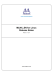
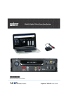
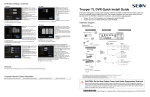
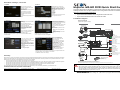
DVR Menu Settings, Continued
9 Speed
10 GPS
GPS Display: If a GPS receiver is
installed, select On to display the
coordinates on the play view overlay.
GPS Time: Select On to have the play
view overlay time set by the GPS.
UTC Reference: Set the time zone:
-4 Atlantic
-5 Eastern
-6 Central
-7 Mountain
-8 Pacific
If selecting GPS, format the drive after
the configurations are done.
Speed Display: If GPS is installed,
select GPS. GPS sensors are
replacing the vehicle speed sensor
calibration system.
Speed Units: Choose MPH for US or
KPH for Canada.
Click Calibrate only if Pulse is
selected from Speed Display.
Click Back to save the menu
settings.
In the Alarms and Signals menu, click
GPS.
11 Network
Click Back to save the menu settings.
In the Configuration main menu click Network.
Users logging on to the DVR locally or
remotely should have password
control to protect the DVR from being
accidentally reconfigured.
Leave the default Admin user and add
other users with access levels as
needed.
Enter user names, passwords, and
assign levels.
Use the IP address shown to
communicate with the DVR over the
internet with vMax Web.
If the DVR is attached to a Wi-fi
bridge, change these settings to
those supplied by the system
administrator.
If the IP information is changed and
saved in a configuration file for
upload to other DVRs, their settings will have to be updated as well.
See DVR Configuration Uploads, on page 28 in the TL DVR Installation Guide.
Click User Levels.
13 System
• Admin user has complete DVR
control.
• Configure user cannot edit user
levels or IP settings.
• Playback user can only view and archive recordings.
Click Back to save the menu settings.
In the Configuration main menu click System.
14 Create/Load Configuration File, Format Drive
Disk Full, HD Failure: Leave Off
unless your network is configured to
receive emails from the DVR.
Password Enable: Leave Off unless
instructed otherwise.
Audio Output Channel: Select the
audio channel that will be available
from the audio RCA port on the front
of the DVR.
vMax Web Timeout: leave at default
10 minutes.
Click Program Update.
This Quick Start guide is intended as a basic DVR install and setup reference. Review it completely before
installing the DVR. The complete installation and user guides to the DVR are available for view or download at
www.seon.com/support/documents.html.
•
Explorer MX-HD Installation and Configuration Guide 700-0159
•
Explorer MX-HD Mobile DVR User Guide 700-0160
Installation Diagram
12 Users
Setting Type: Leave at default Static
IP setting.
Explorer MX-HD DVR Quick Start Guide
Store Current Configuration:
Select USB Device as the file
saving destination.
Plug a USB memory device into
the front of the DVR. Click Store
to save the file on the USB
memory device.
Load: For details on uploading
configurations to the DVR, see
DVR Configuration Uploads, on
page 28 in the TL DVR
Installation Guide.
Update: Firmware updates can
also be delivered by a USB
device. The DVR will reboot when updates are done.
Format: Format the hard drive when the configuration is complete and tested and
before final delivery of the installation to the customer.
Click Back to save the menu settings.
Explorer® MX-HD
Typical Plus System Setup
Peripherals
Vehicle Electrical Interface
Seon System
Supports Four
Analog Cameras
MX-HD DVR Rear Panel
Power over Ethernet
Switch
SPEED
3 wires
CHW HD Camera
ALARMS
Optional Accessories
Alarm 1 (orange)
Alarm 2 (blue)
Alarm 3 (violet)
GPS Receiver *1
Alarm 4 (gray)
Diagnostic Indicator/
Alarm Button *3
Alarm 1-4 Ground (black)
4 wires
or
RGY Illuminator *3
SIGNALS
Smart-Link
Left Turn (black)
8 wires
Seon Design Inc. (Seon) warrants the cameras and components listed below against defects in workmanship and materials provided that such defects
appear or are discovered within the respective periods specified below and provided further that the purchaser of such products notifies Seon of such
defects within thirty (30) days of the appearance or discovery of such defects:
•
Three (3) years from date of purchase, parts and labor on all Cameras
•
Three (3) years from date of purchase, parts and labor on the Explorer® Premier, DX, TX, EX, MX, and Trooper® TL series mobile DVR Systems
•
One (1) year from date of purchase, parts and labor on the Smart Reach® Wireless systems and other Wireless products
•
One (1) year from date of purchase, parts and labor on the VML Controller and other vMax Live Plus hardware products
•
One (1) year from date of purchase, parts and labor on all other products and accessories
All service/replacement parts and repairs are warranted for a period of 90 days. For full warranty information, go to www.seon.com.
Customer Service Contact Information
Toll free telephone 1-877-630-7366
Local telephone 604-941-0880
Email: [email protected]
Web: www.seon.com
Stop (green)
Portable Video Monitor*2
To DVR
VIDEO OUT
Brake Signal (red)
5 wires
Warning (brown)
Right Turn (white)
1A
Smart-Reach Lite
(Wi-fi)
Laptop
Configuration
POWER
Vehicle Switched + 12V (yellow)
3 wires
Warranty
Red - Not used
Green - Speed sensor high
Black - Speed sensor low
To DVR
ETHERNET
Input
Battery Negative (black)
5A
Vehicle + 12V (red)
XELR-8 Inertia Sensor
To DVR
CONTROL Input
*1 For ease of installation and better speed tracking, Seon recommends using a GPS receiver.
*2 The portable video monitor can be used from the front or back panel DVR connectors.
*3 The Diagnostic Indicator/Alarm Button and RGY Illuminator Display are not interchangeable, a different Smart-Link unit is required to use either one.
CAUTION: Do Not Use Output Power from Noise Suppression Solenoid
Many school buses include a separate solenoid to power noisy items such as fans. The noise suppression solenoid’s power
out can be easily confused with true ignition power. If there is no apparent output from any obvious ignition sources, consult
the bus schematic or bus manufacturer to locate a proper power on source for the DVR. Don’t assume that the tested wire
operates exactly like an ignition wire, it may not.
*700-1004* © Seon Design Inc. | March 2013 | All rights reserved. www.seon.com | 700-1004 R002
DVR Installation
DVR Menu Settings
The DVR can be installed horizontally or vertically or at an angle. Do not install the DVR upside down.
Click Back on menus to save updated settings.
1 Main Menu
2 Configuration Menu
In the Configuration menu, click Time/
Date to access the Time and Date
menu.
In the main menu, click Configuration to
access the Configuration menu.
MX-HD ONLY
Mounting
plate
Locking front cover
(reversible)
3 Time/Date
Door lock
Cable cover
DVR hard drive
Cable grommets
Knockouts
4 Titles/Display
Time Format: Choose 12 or 24 hour
display.
Time: Input the correct time.
Date Format: Select the date format.
Date: Input the date.
Note: When GPS is installed and GPS
time is selected in the Alarm/Signal Speed
and GPS settings menus, then the date
and time automatically update when the
GPS detects satellites.
Auto Daylight Saving: Leave this On and
at default dates unless in an area that does not use daylight savings (ex: Arizona,
Saskatchewan).
Click Back to save the menu settings. In the Configuration menu, click Title/Display.
5 Record
CAUTION: Heat or Moisture Damage Risk
Do not install the DVR in a location where the unit is exposed to excessive heat or moisture. Installation close to
extreme heat or moisture will void the product warranty.
Route the wiring and cables away from sharp edges that might damage the insulation. Avoid sharp bends in the
cable.
Contact Seon before attaching the DVR to other equipment in the vehicle.
Powering the System On
Turn the vehicle ignition on to power up the DVR. When the PWR LED shows green and the HDD LED flashes
red, the DVR is operating normally and recording.
DVR Menu Setup
Depending on any options installed, the DVR needs to have some menu settings updated to operate properly.
To access the DVR menu settings, connect a portable video monitor and mouse to the DVR.
Connect a USB mouse to a USB port on the DVR front panel
Connect a portable video monitor to VIDEO OUT on the DVR front panel
MX-HD DVR
MX-HD ONLY
USB Mouse
Portable
Video Monitor
Camera Views
Right-click anywhere in this view to access the DVR menus.
Click Back to return to this view after updating menus.
Main Title: Enter the bus number.
Main Title Display: Leave On.
Camera 1-4: Enter camera titles that
describe the views they are recording,
such as:
Front
Step
Mid
Rear
Click Back to save the menu settings.
In the Configuration menu, click Record.
6 Cameras
Time Format: Choose 12 or 24 hour
display.
Time: Input the correct time.
Repeat Record: Leave On for the hard
drive to record over the first recordings
when it is full.
Record Delay On Time: Leave at default
to let the bus voltage settle after the bus
starts up, to prevent voltage drops affecting
the DVR.
Record Delay Off Time: Set to 10-20
minutes to keep the DVR and cameras on
after the ignition turns off to record the bus post-trip check.
Power Delay Off Time: This starts up after Record Delay Off time ends. If Wi-Fi is
used, set to 2 hours or more. If no Wi-fi, leave at default.
Alarm Partition Size: Leave Off unless instructed otherwise.
Click Camera to access camera settings. See the next screen.
Click Record2 and set unused Channel speeds to Off, so the DVR will not generate
video loss events.
Click Back to save the settings.
7 Signals
Set unused Channel speeds to Off,
so the DVR will not generate video
loss events.
New titles will display here as well as on
the camera view overlays.
Speed: Leave the channel speed at
default settings unless you have special
requirements.
Resolution: Leave the channel
resolution at default settings unless you
have special requirements.
Quality: Leave the channel quality at
default settings unless you have special requirements.
Audio: Leave audio settings On unless the camera is mounted on the exterior of the
vehicle.
Click Back to save the Camera menu settings and to return to the Record menu.
In the Configuration menu, click Alarm/Signal. In the Alarms and Signals menu, click
Signals.
8 Alarms
Label: For signals 1-5, select from: LT left
turn, STP stop, BRK brake, WRN warning
light, and RT right turn.
The labels can be edited.
Signals 6-10 are available for advanced
signal wiring if required. Maximum 3
character.
Level: Set all signal levels as required.
Choose Active High if the circuit you are
installing into rests at 0 VDC and goes to
12 VDC when active.
Choose Active Low if the circuit rests at 12
VDC and drops to 0 VDC when active.
Alarm: If a signal is used to trigger an alarm, that alarm’s input must also be set up in
the Alarms menu.
Click Back to save the menu settings. In the Alarms and Signals menu, click Alarms.
Set unused Channel speeds to Off,
so the DVR will not generate video
loss events.
Alarm: Alarm 1 comes from the DVR
alarm button. Alarm 2-4 can come
from signals.
Duration: Applies to Alarm 1 only.
Set the Duration for how long the
DVR will record video flagged as an
alarm.
Speed, Quality, and Resolution: For
each alarm, select higher settings for
better video while the alarm is recording.
Input: Applies to Alarm 1 only. Choose Normally Open or Normally Closed,
depending on the switch type used.
Pre-Alarm: Select how many seconds of pre-alarm video is included in the flagged
alarm recording.
Email: Leave at default unless instructed otherwise.
Wake: Leave at default unless instructed otherwise.
Click Back to save the menu settings.
In the Alarms and Signals menu, click Speed.
*700-1004* © Seon Design Inc. | March 2013 | All rights reserved. www.seon.com | 700-1004 R002