1
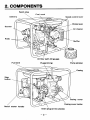
PUMP
MODEL
EW2OOTR
EW3OOTR
EW400TR
INSTRUCTION MANUAL
I ISSUEEMD-PU0835 I
piEGKq
FOREWORD
Thank you for purchasing a Makita trash pump.
This manual covers operation and maintenance of trash pumps.
All information in this publication is based on the latest product information available at the time of approval for printing.
Please read this manual carefully before operating.
CONTENTS
Page
1. PUMP SAFETY ...............................................
2. COMPONENTS ...............................................
3. PREPARATIONS FOR STARTING .............................
4. STARTING THE ENGINE ......................................
5. OPERATION ..................................................
6. STOPPING THE ENGINE .....................................
7. MAINTENANCE SCHEDULE ..................................
8 . "HOW-TO" MAINTENANCE ....................................
9.TROUBLESHOOTlNG ........................................
10. PREPARATIONS FOR STORAGE .............................
11. OIL SENSOR lNSTRUCTlONS ................................
1
2
3
5
7
a
9
10
12
14
15
ID
PUMP SAFETY
Please make sure you review each precaution carefully.
SURROUNDINGS
H
H
H
Operate the pump on a stable, level surface free of small rocks, loose gravel,
etc.
Keep pump at least 3 feet (1 meter) away from buildings.
Keep pump away from flammables and other hazardous materials (trash,
rags, lubricants, explosives).
FIRE PREVENTION
m
H
H
H
Be sure to stop the engine prior to refueling.
Do not overfill fuel tank.
If spillage does occur, wipe away spilt fuel thoroughly and wait until fuel has
dried before starting engine.
Do not operate while smoking or near an open flame.
EXHAUST PRECAUTION
H
H
H
Never inhale exhaust gasess; they contain carbon monoxide, a colorless,
odorless, extremely dangerous gas which can cause unconsciousness or
death.
Never operate the pump indoors or in an enclosed area such as a cave or a
tunnel.
Exercise extreme care when operating near people and domestic animals.
OTHER IMPORTANT POINTS
H
H
H
H
H
Keep away from rotating parts and hot parts while the pump is running.
Never permit anyone to operate the pump without proper instructions.
Know how to stop the pump quickly and understand operation of all the
controls.
Tighten the fuel tank cap securely and close the fuel cock before transit.
Check the engine oil and refill if necessary.
Carefully check fuel pipes and joints for looseness and fuel leakage.
-1-
Spark plug
\
Fuel cock
Speed control lever
Fuel tank
Plug(priming)
Drain plug (at two places)
-2-
\
Pump strainer
3. PREPARATIONS FOR STARTING
1. Connect the suction hose.
Use a reinforced-wall or wire braided hose to
prevent suction collapse. Since the pump’s
self-priming time is directly proportional to
hose length, a short hose is recommended.
tion hose. Gravel or debris sucked
into the pump will cause serious
2. Connect the discharge hose.
When using a fabric hose, always use a hose band to prevent the hose from
disconnecting under high pressure.
3. Check the engine oil level.
Engine oil is a major factor affecting engine performance and service life.
Nondetergent or vegetable oils are not recommended.
Use oil classified “SC” or higher grade.
If the oil level is below the fill level line on the dipstick, refill with the proper oil (see
table) to edge of the oil fuller neck.
Be sure to check the oil level on a level surface with the engine stopped.
E
Single grade
Multlgrade
I
Ambient
- 0 -10
I
I
I
I
0
10
20
30
-3-
I
40’C
4. Check the fuel level.
If level is low, fill to the shoulder of the fuel filter. Use fresh, clean automotive
gasoline.
5. Check the priming water.
It is recommended that the water chamber of
pump casing should be primed with full of
water before operating.
.
C
O
,A
N
U
I]T
Never attempt to operate the pump
without priming water or the pump
will overheat. Extended dry operation will destroy the mechanical seal.
If the unit has been operated dry,
stop the engine immediately and allow the pump to cool before adding
priming water.
-4-
4. STARTING THE ENGINE
1. Open the fuel cock.
2. Set the speed control lever to “START.”
-.
..
. .
.
EW400TR
3. Close the choke.
the engine is warm or the ambient temperature is high, close the choke
half-way, or keep it open fully.
If the engine is cold, or the ambient temperature is low, close the choke.
m If
.
I-\
Choke knob
EW400TR
-5-
I
4. Pull the starter handle slowly until re-
sistance is felt. This is the "compression"
point. Return the handle to its original
position and pull swiftly.
Do not pull out the rope all the way.
I After starting the engine, allow the
starter handle return to its original
position while still holding the handle.
-6-
5. OPERATION
1. After starting the engine, gradually open choke by turning the choke lever and
finally keep it open fully.
H
Do not fully open the choke immediately when the engine is cold or the
ambient temperature is low, because the engine may stop.
EW400TR
2. After the engine starts, set the speed
control lever at the low speed position (L)
and warm it up without a load for a few
minutes.
Gradually move the speed control lever toward the high speed position (H) and set it at
the required engine speed.
NOTE :
Whenever high speed operation is not required, slow the engine down (idle), by moving the speed control lever to save fuel and
extend engine life.
Lock the control lever by
turning wing nut clockwise.
EW400TR
- 7 -
6. STOPPING THE ENGINE
1. Set the speed control lever to the low
speed position and allow the engine to
run at low speed for 2 or 3 minutes
before stopping.
2. Keep depressing the STOP B U T O N
until the engine stops.
Do not stop the engine suddenly when it
is running at high speed.
3. Close the fuel cock.
4.
Pull the starter handle slowly and return
the handle to its original position when
resistance is felt.
NOTE :
The above operation is necessary to prevent
outside moist air from intruding into the
combustion chamber.
STOPPING ENGINE WITH THE FUEL COCK
Close the fuel cock and wait for a while until the engine stops.
Avoid letting fuel remain in the carburetor long period, or the passages of the
carburetor may become clogged with impurities, and malfunctions may result.
- 8 -
DAILY INSPECTION
Before running the pump, check the following service items:
Enough fuel.
m Excessive vibration, noise.
Clean air cleaner element.
Safe surroundings.
Enough clean engine oil.
D Leakage of gasoline and engine oil.
Loose or broken bolts and nuts.
Check the priming water.
PERIODIC INSPECTION
Periodic maintenance is vital to the safe and efficient operation of your pump.
Check the table below for periodic maintenance intervals.
The following chart is based on the normal pump operation schedule.
8 hours
(daily)
Clean engine and check bolts and nuts.
50 hours
(weekly)
I 0(daily) I
200 hours
(monthly)
I
Check and refill engine oil.
0 (Refill daily up to the upper limit.)
Change engine oil.
(Initial
20 hours)
Clean spark plug.
I
I
I
1
I
I
l o 1
I
0
Remove the pump casing and clean.
~
1000
hours
0
0
Clean air cleaner.
Clean fuel strainer.
500
hours
I
I
l
o
~
0
Clean and adjust spark plug gap.
0
Clean and adjust carburetor.
Clean cylinder head.
I
I
I
0
0
Adjust valve clearance.
Overhaul engine.
0
-[CAUTION]
Replace rubber pipes for fuel passage every two years. If fuel leakage is
found, replace the pipe immediately.
-9-
a. "HOW TOWAINTENANCE
INSPECTING THE SPARK PLUG
w
Clean off carbon deposits on the plug
electrode using a plug cleaner or wire
brush.
Check electrode gap.
Adjust it to between 0.02 and 0.03 inches.
(0.6 and 0.7")
0.6-0.7mm
-&-
(0.02-0.03in.)
ENGINE OIL CHANGE
Initial oil change......20 hours of operation
Thereafter.. .Every 50 hours of operation
:CAUTION]-
..
..
Make sure the fuel cap is tightly secured to avoid spillage.
When changing oil, stop the engine
and loosen the drain plug.
Tighten the drain plug before refilling.
Refer to the recommended oil table
on page 3.
Always use the proper grade and
clean oil. If the engine oil is contaminated, there is not enough or it is of
poor quality, engine life will be shortened.
CLEANING FUEL STRAINER
Check for water or contaminants in the fuel strainer.
To remove contaminants, close the fuel cock and remove the strainer cup.
After removing contaminants and water, wash the strainer cup with kerosene.
Reinstall it securely to prevent leakage.
- 10 -
SERVICING THE AIR CLEANER
Maintaining an air cleaner in proper condition
is very important. Dirt induced through improperly installed, improperly serviced or inadequate elements, wears out engines. Keep
the element always clean.
(a) Unlock the cover and remove the cleaner
element.
(b) Inner element:Wash the element with
kerosene, then soak it in mixed oil (Kerosene (3):Engine oil (1)).
Drain the mixed oil.
(c) Outer e1ernent:Wash the element with
kerosene, then dip it into the mixed oil
(Kerosene (3):Engine oil (1)).
Squeeze out the mixed oil. (Do not twist.)
COVER
OUTER
INNER
ELEMENT ELEMENT
FUEL PIPE REPLACEMENT
Replace the fuel pipe every 2 years.
If the fuel pipe is found leaking, replace it immediately.
CHECKING BOLTS, NUTS AND SCREWS
Retighten loose bolts and nuts.
Check for fuel and oil leaks.
Replace damaged parts with new ones.
CLEANING PUMP INSIDE
Turn the knob counterclockwise and open the casing cover holder.
Pull the casing toward you, and then remove the casing and the inner casing.
Clean the inside of pump casing and casing cover with clean water.
- 11 -
Engine does not start.
(See page 13.)
Pump does not
run.
I
Sticking of impeller (Disassemble and clean.)
Sucking air at suction side
(Check piping at suction side.)
Pumping volume
is small.
Drop in engine output
(Consult your nearest dealer.)
Breakage of mechanical seal
(Consult your nearest dealer.)
High suction lift (Lower.)
Suction hose is too long or thin.
(Use a thick hose in minimum length.)
Leak of water from water passage
(Stop leaking.)
Clogging of foreign substance in impeller
(Disassemble and clean.)
Wear of impeller
Strainer is clogged (Clean.)
Engine speed is too low
(Consult your nearest dealer.)
Pump does not
self-prime.
c
7
Suction of air at suction side.
(Check piping at suction side.)
Insufficient priming water inside pump casing
(Prime fully.)
Imperfect tigtening of drain plug
(Tighten the plugs completely.)
Engine speed is too low.
(Consult your nearest dealer.)
Sucking air from mechanical seal
(Consult your nearest dealer.)
- 12 -
fore you take the pump to your
Makita dealer.
If you still have trouble after completing the checks, take the pump
to your nearest Makita dealer.
M Before testing, carefully wipe off
spilled fuel.
Put the plug as far away from the
spark plug hole as possible.
Ground the side of the electrode to
any engine ground.
1. Remove the plug and connect it to the plug cap.
Pull the starter handle while putting the plug
against the engine ground.
Is there a
-across the
2. Try with a new plug if the spark is weak or no
spark flies.
electrode?
3. The ignition system is faulty if there is no spark
with a new plug.
Take your pump to your nearest Robin dealer.
Starting
failure
t
I
r
1
1. Pull the starter handle slowly and check if
resistance is felt.
” there
enough compression?
2. If little force is required to pull the starter handle,
check if the spark plug is tightened firmly.
3. If the spark plug is loose, tighten it.
I-
4. If compression is still low, consult your nearest
dealer.
1
Is the spark
plug wet withfuel?
- 1.
Choke (close choke lever) and pull the starter
handle five or six times.
Remove the plug and check if its electrode is
wet. If the electrode is wet, fuel is well supplied
to your engine.
- 2.
When the electrode is dry, check where the fuel
stops. (Check the fuel intake of the carburetor
and fuel strainer intake.)
- 3.
In case the engine does not start with well
supplied fuel, try using different fuel.
- 13 -
10. PREPARATIONS FOR STORAGE
~~~
I
~
Drain all water from the drain plug.
[CAUTION
retightening drain plug, be
sure to clean the drain plug and the
thread of casincl. Otherwise, the
,
I When
thread may be da6aged.
1u
I I
J
1
Remove the strainer cup, and open the strainer cock to discharge the fuel
from the fuel tank.
Remove the carburetor float chamber bolt from the bottom and discharge fuel
from the carburetor. (NO SMOKING !)
Change the used engine oil with fresh oil.
Remove the spark plug, pour about 5 cc of engine oil into the cylinder, slowly
pull the starter knob of the recoil starter 2 or 3 times, and tighten the spark
Plug.
Slowly pull the recoil starter knob until resistance is felt and leave it in that
position.
Store the pump in a dry place free from sand or dust.
Always keep the pump covered.
- 14 -
11 OIL SENSOR INSTRUCTIONS
OIL SENSOR (OPTION)
(a) The oil sensor detects the fall in oil level in
the crankcase and automatically stops the
engine when the oil level falls down below
the predetermined level.
(b) When engine has stopped automatically,
check the oil level. Refill engine oil to the
upper level and restart the engine.
(c) If the engine does not start by usual
starting procedures, check the oil level.
when refilling with oil. Remove oil
filler cap on the opposite side of
carburetor.
- 15 -
MAKITA LIMITED ONE YEAR WARRANTY
Warranty Policy
Every Makita tool is thoroughly inspected and tested before leaving the factory. It is
warranted to be free of defects from workmanship and materials for the period of
ONE YEAR from the date of original purchase. Should any trouble develop during
this one-year period. retum the COMPLETE tool, freight prepaid, to one of Makita’s
Factory or Authrorized Service Centers. If inspection shows the trouble is caused by
defective workmanship or material, Makita will repair (or at our option, replace)
without charge.
This Warranty does not apply where:
repairs have been made or attempted by others;
there is evidence of normal wear and tear;
0 The tool has been abused, misused or improperly maintained;
0 alterations have been made to the tool.
Defects are due to the use of parts, accessories or attachments which are not Makita
genuine products, specifically recommended for use with this tool.
Damage may be caused in transit. (This must be the responsibility of the carrier.)
Claims arise from regulations such as for noise levels, exhaust gas emissions. etc. This
product has been operated for racing purposes or other competitve activities. This
product has been employed for powering equipment that is operated on, in or near
water or explosive atmospheres.
The following parts are expendable (not durable), so warranty does not apply:
Expendable parts including, but not limited to:
Spark plugs, packings. gaskets, rubber materials. washers. nuts, V-belt, engine oil,
grease, paper elements , brushes, mechanical seal, pump impeller and volute casing.
IN NO EVENT SHALL MAKITA BE LIABLE FOR ANY INDIRECT,
INCIDENTAL OR CONSEQUENTIAL DAMAGES FROM THE SALE OR USE
O F THE PRODUCT. THIS DISCLAIMER APPLIES BOTH DURING AND
AFTER T H E TERM OF THIS WARRANTY.
MAKITA DISCLAIMS LIABILITY FOR ANY IMPLIED WARRANTIES,
INCLUDING IMPLIED WARRANTIES O F “MERCHANTABILITY” AND
“FITNESS FOR A SPECIFIC PURPOSE,” AFTER THE ONE-YEAR TERM O F
THIS WARRANTY.
This Warranty gives you specific legal rights, and you may also have other rights
which very from state to state. Some states do not allow the exclusion of limitation of
incidental or consequential damages, so the above limitation or exclusion may not
apply to you. Some states do not allow limitation on how long an implied warranty
lasts, so the above limitation may not apply to you.
Makita Corporation
3-18-8, Sumiyoshi-cho
Anjo, Aichi 446 Japan
PRINTED IN JAPAN