1
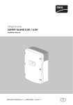
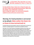
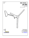
MidNite Solar Communication Adapter
User Manual
P/N 10-269-1 Rev-A
Notice of Copyright
MidNite Solar Communication Adapter User’s Manual
Copyright © 2013 all rights reserved.
Disclaimer
Unless specifically agreed to in writing, MidNite Solar Inc.
(a) Makes no warranty as to the accuracy, sufficiency or suitability of any technical or other
information provided in its manuals or other documentation.
(b) Assumes no responsibility or liability for loss or damage whether direct, indirect,
consequential or incidental, which might arise out of use of such information. The use of any
such information will be entirely at the user's risk.
Contact Information
Telephone: 360.403.7207
Fax:
360.691.6862
Email:
[email protected]
Web:
www.midnitesolar.com
MidNite Solar Communication Adapter User Manual Rev A
APPLICATION and DESCRIPTION of OPERATION
MidNite Solar’s Communication Adapter is a software protocol converter for creating a communications
link between SMA’s Sunny Island inverter and MidNite Solar’s Classic charge controllers, which allows
these products to work together as a system. Translating Midnite Solar’s communication protocol into
SMA format, and vice-versa, allows up to four Classics to communicate with a single Sunny Island
inverter. As a system the Classics are able to report their energy production data, (i.e. - voltage, current
and power), to the Sunny Island and from there on to the Sunny WebBox, in a similar manner as SMA’s
charge controllers report their power production. Going the other way the Sunny Island inverter acts as
the system controller, telling the Classics the appropriate voltage set point for the battery state of
charge at the time.
The Communication Adapter intercepts PV and battery status messages formatted in the Classic
controller’s native protocol, MODBUS, and translates them into SMA’s packet protocol, ComSync. Then
the Communication Adapter forwards them to the Sunny Island. Going the other way, the
Communication Adapter receives and translates battery charge voltage set points initiated by the Sunny
Island into MODBUS packets and sends them to the Classics. This allows the connection of up to four
Classics to each Sunny Island inverter in a similar manner as SMAs charge controllers are connected into
larger systems. In the Classic, a special SMA mode allows the battery absorb, float and equalize charge
settings to be received from the Sunny Island inverter.
BEFORE GETTING STARTED
Refer to the System Overview Diagram when planning the system. Up to four Classics may be
connected to each Sunny Island inverter. MODBUS communication cables are connected between each
Classic, then a final MODBUS cable is connected from the first Classic to the Communication Adapter.
An 8-pin Ethernet-style cable is used for ComSync and is connected from the Communication Adapter to
the Sunny Island. The Communication Adapter gets its power from the first Classic. There is no wall
transformer or connections other than the MODBUS and ComSync cables.
NOTE The System Overview Drawing is simplified for instructional purposes. The wiring details may vary
according to the installation requirements. All wiring must be performed in accordance with local
codes. Professional installation is recommended.
MOUNTING
The MidNite Solar Communication Adapter is designed for indoor installation only and is provided with
flanges for wall mounting. Mount the unit in a convenient location between the Classics and the Sunny
Island inverter. There are LED indicators along the front edge of the unit, so pick a location and height
so that the front side CAN cable (RJ-45) connectors can be visible. Avoid a lot of excess cable length to
minimize the chance of stray noise pick-up.
2|Page
10-269-1
REV: -
MidNite Solar Communication Adapter User Manual Rev A
Typical Wall Mounted Connections
TERMINATION JUMPERS
SMA’s ComSync cable conforms to the CAN bus specification, a very fast and reliable system developed
by Bosch for vehicle applications. Most CAN devices have an IN and an OUT connector and a provision
for terminating the bus, a 120 ohm resistor at each end of the bus. The bus connects a linear string of
CAN devices into a network. If a device is located in the middle of the bus, no termination is used. The
two end device require a terminator. The Sunny Island uses a terminator that looks like an RJ-45
connector without a cable. If the Sunny Island is the last device on one end of the bus, plug the
terminator into the RJ-45 receptacle on the Sunny Island that isn’t connected to another CAN device.
The vast majority of applications the Communication Adapter will be the last device on the ComSync bus
so the CANBUS OUT jack will be unused. For this reason the Communication Adapter’s bus termination
resistor is internal. If the system design requires CAN devices to be connected to both connectors, you
must remove the cover from the unit and place the termination jumper, CON 7, on one of the pins only.
Place CON 7
terminaton
jumper on
ONE of the
pins if used
in the
middle of
the bus.
3|Page
10-269-1
REV: -
MidNite Solar Communication Adapter User Manual Rev A
remote
remote
remote
remote
slave/out
master/in
slave/out
slave/out
slave/out
master/in
master/in
master/in
Classic
#13
Classic
#12
Classic
#11
CAN Bus
Terminator
(CON 7)
COM Jumpers
Install toward the
top
Classic
#10
GND Connection
(if required)
SMA Converter
(Address 9)
SMA-A
SMA-B
TO SLAVE
FROM
MASTER
SUNNY ISLAND
Inverter
USB
LED 1
MODBUS Cable
LED 4
LED 2
LED 3
Power is
Supplied via MODBUS
Cable from Classic
#10
CAN Bus
Terminator
Installed
BKUP
VTG
CUR
COM
SYNC
OUT
COM
SMA
OUT
COM
SYNC
IN
COM
SMA
IN
CAN BUS Cable (Ethernet)
Classic #10-13 is the MODBUS address of that Classic
System Overview Diagram (Typical Installation)
4|Page
10-269-1
REV: -
MidNite Solar Communication Adapter User Manual Rev A
CLASSIC ADDRESSING and CONNECTIONS
The Classics communicate with the Communication Adapter without confusion by having unique
addresses for each Classic. The addresses need to be set by the installer when commissioning the
system. The Classics are set to MODBUS addresses #10, #11, #12, and #13 (See Overview Diagram).
Note what each Classic’s address is when making connections. If only one Classic is used with the Sunny
Island, the controller’s address must be #10, which is default, so there is no need to change it.
If two Classics are installed, the second Classic’s address will be #11. Connect a communication cable
from the MASTER/IN jack on the first Classic (#10) to the SLAVE/OUT jack on the second Classic. If three
Classics are installed, the third controller’s address will be #12. Connect a communication cable from the
MASTER/IN jack on the second Classic (#11) to the SLAVE/OUT jack on the third Classic. If a fourth
Classic will be installed, its address will be #13. Connect a communication cable from the MASTER/IN
jack on the third Classic (#12) to the SLAVE/OUT jack on the fourth Classic. There is no connection to the
MASTER/IN jack on the last Classic (typically #13).
Connect a CAT-5 Ethernet cable of suitable length from the SLAVE/OUT jack on the FIRST Classic (#10)
to the RJ-11 connector at the far right end of the Communication Adapter. Connect one end to Classic
#10. Do not plug in the end for the Communication Adapter quite yet. The other RJ-11 connector
(MODBUS OUT) is reserved for future use.
Connect one end of the ComSync cable from the Sunny Island to the CANBUS IN connector on the
Communication Adapter. Connect the other end of the ComSync cable to the ComSyncIn connector on
the Sunny Island inverter (center of the three RJ-45 connectors at the bottom right). If there are no
other devices on the Com Sync (CAN) bus the terminator should be installed in the RJ-45 ComSyncOut
jack (directly above). If there are other CAN devices in the system the terminator should be installed on
the last CAN device. The Communications Adapter comes with the terminator jumper (CON7) factory
installed since the CANBUS OUT connector is generally not used.
MESSAGES
There are several signals passed between the Sunny Island and the Classics which are translated by the
Communication Adapter. The Communication Adapter periodically requests battery and PV status from
each classic. Once it has read all the Classic status values it converts the messages into ComSync format
and sends them on to the Sunny Island. Note that the times given are approximate and depend on how
many Classics there are in the system and how busy the system is
Battery Current is requested from each Classic, converted to ComSync encoding and sent to the Sunny
Island approximately every five seconds.
PV Voltage is requested from each Classic, converted to ComSync encoding and sent to the Sunny Island
approximately every five seconds.
Battery Voltage is requested from each Classic, converted to ComSync encoding and sent to the Sunny
Island approximately every five seconds.
PV Power is requested from each Classic, converted to ComSync encoding and sent to the Sunny Island
approximately every five seconds.
5|Page
10-269-1
REV: -
MidNite Solar Communication Adapter User Manual Rev A
Battery Set Voltage is sent by the Sunny Island to the Communication Adapter in ComSync format and is
processed into three separate MODBUS messages. They are ABSORB voltage, FLOAT voltage,
and EQUALIZE voltage. The same set voltage value is used for all three parameters and sent to
each Classic (up to twelve MODBUS messages) approximately every 30-60 seconds. Any offset
adjustments are made in the Classic.
COMISSIONING THE SYSTEM
When everything is ready to go, energize battery power to the Classics. The Communications Adapter is
powered from Classic #1 (MODBUS address #10) via the communications cable.
Set (verify) that the Classic controllers’ addresses are set to #10, #11, #12, and #13 for Classics 1-4
respectively.
On EACH classic, go to MAIN MENU->MISC->COMM->MORE and select the SMA option. Save it and
REBOOT the Classic.
Verify that the MNGP displays read proper battery voltages, and that the Classics appear to be operating
properly.
Energize PV power to the Classics.
Go the Communication Adapter and plug in the MODBUS cable coming from the first Classic (#10). The
LEDs should start showing activity within a few seconds. The Communication Adapter may take a
minute or two to establish communication and collect voltage, current and power data for all the
Classics in the system.
Use the Sunny Island menu buttons to navigate to the External Charge Controller meters. (Mrnus #142 #145). Verify that the Sunny Island display shows the expected voltages, currents and power readings.
Check that the display at the Sunny WebBox agrees with the Classic MNGP displays. The Classic
Software revisions for are displayed on the Sunny WebBox as the software build number divided by 100.
For example, the Classic status screen for unit 1 shows: 1686: 1/15/2014
WebBox Spot Values screen for that Classic will say:
95
Sic1SWVers 16.86
as shown on the screen capture below.
The four values for each charger are displayed as: EgyCntIn,PvPwr, SWVers, TdyEgyCntIn, and are
displayed on the Spot Values display. Refer to the Sunny Island and Sunny WebBox for details.
6|Page
10-269-1
REV: -
MidNite Solar Communication Adapter User Manual Rev A
Classic 1
Classic 2
Classic 3
Classic 4
7|Page
10-269-1
REV: -
MidNite Solar Communication Adapter User Manual Rev A
Classic Power
CAN BUS Activity
MODBUS Error
MODBUS Transmit
MODBUS Receive
COMMUNICATION STATUS LEDS
LED OPERATION
There are four green LEDs on the Communication Adapter, two below each RJ-45 jack numbered 1-4
from left to right. All four LEDs come on once briefly at power up.
LED 1 will blink on and off slowly (five second interval) when connected to a Classic (if power is applied).
This shows that the software is working. If the ComSync cable is connected and software receives the
Sunny Island’s “Battery Set Voltage” command, the blink rate of LED1 will increase to approximately
once per second. If the ComSync bus is working properly a noticeable difference in blink rate will be
observed when the cable is plugged in.
LED2 flashes briefly when a MODBUS request has been correctly received from a Classic. There typically
are four packets received per Classic in a burst with a slight pause before the next Classic is polled. If
there is only one Classic four quick blinks will be seen. If there are two Classics, typically two sets of four
quick blinks will be seen. If there are three or four Classics, there will be three or four sets.
LED3 flashes briefly when the “Battery Set Voltage” packet is sent out to the classics. If things are
working properly, typically several blinks in a burst will be seen repeated on about thirty second
intervals.
LED4 is a MODBUS error indicator. It briefly blinks once for each MODBUS CRC, timeout, or exception.
A few occasional blinks are normal as data packets can and do collide and retries are automatically
generated, however LED4 should not blink very often.
8|Page
10-269-1
REV: -
MidNite Solar Communication Adapter User Manual Rev A
MIDNITE SOLAR INC. LIMITED WARRANTY
MidNite Solar Power electronics, sheet metal enclosures and accessories
MidNite Solar Inc. warrants to the original customer that its products shall be free from defects in materials and
workmanship. This warranty will be valid for a period of two (2) to five (5) years depending on the product.
At its option, MidNite Solar will repair or replace at no charge any MidNite product that proves to be defective
within such warranty period. This warranty shall not apply if the MidNite Solar product has been damaged by
unreasonable use, accident, negligence, service or modification by anyone other than MidNite Solar, or by any
other causes unrelated to materials and workmanship. The original consumer purchaser must retain original
purchase receipt for proof of purchase as a condition precedent to warranty coverage. To receive in-warranty
service, the defective product must be received no later than two (2) weeks after the end of the warranty period.
More details at http://www.midnitesolar.com/
Returning for Service: When returning any MidNite Solar product for service or repair, contact customer
service by email at: [email protected] for further instruction and an RMA (Return Material
Authorization) number before sending the unit to MidNite Solar.
9|Page
10-269-1
REV: -