1
Instruction Manual
Meade Model 4504
4.5" (114mm) Equatorial Reflecting Telescope
With Starfinder Electronic Hand Controller
ENTER
MODE
GO TO
SPEED
?
MEADE
STARFINDER
Meade Instruments Corporation
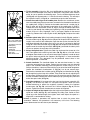
WARNING
NEVER USE A MEADE® TELESCOPE TO LOOK AT THE SUN!
LOOKING AT OR NEAR THE SUN WILL CAUSE INSTANT AND
IRREVERSIBLE DAMAGE TO YOUR EYE. EYE DAMAGE IS OFTEN
PAINLESS, SO THERE IS NO WARNING TO THE OBSERVER THAT
DAMAGE HAS OCCURRED UNTIL IT IS TOO LATE. DO NOT POINT
THE TELESCOPE OR ITS VIEWFINDER AT OR NEAR THE SUN. DO
NOT LOOK THROUGH THE TELESCOPE OR ITS VIEWFINDER AS IT
IS MOVING. CHILDREN SHOULD ALWAYS HAVE ADULT
SUPERVISION WHILE OBSERVING.
How This Manual is Organized
This manual is divided into three major sections.
Part One, "The Basics," presents several "Lessons" that will teach you how to
assemble and use your telescope and Starfinder. If you follow all the Lessons in this
section, you will become familiar with the basic operation of your telescope and the
Starfinder handbox by the end of Part One. This section covers the following procedures:
Lesson 1: Unpacking and Assembly.
How to unpack and assemble the basic telescope and tripod unit.
Lesson 2: Balancing the Telescope.
How to balance the telescope.
Lesson 3: Aligning the Viewfinder.
How to align the viewfinder and insert the eyepiece into the focuser.
Lesson 4: Observing by Moving the Telescope Manually.
How to focus an eyepiece. How to move your telescope manually to make
observations.
Lesson 5: Observing using Starfinder's Arrow keys.
How to install the motor drives. How to change the slew speeds. How to
observe using Starfinder's Arrow keys.
Lesson 6: Tracking Objects.
How to Polar align your telescope. How to observe using automatic tracking.
Lesson 7: Observing using Starfinder's Go To Capabilities.
How to initialize Starfinder and train the drive. How to move around in
Starfinder's menus. How to observe using Starfinder and how to take a
Guided Tour of the night sky.
Part Two, "Starfinder's Controls and Menus," provides more information about
Starfinder's databases and menus.
Part Three, "Caring for Your Telescope," provides information that explains how to
properly maintain your telescope.
The Appendices provide advanced information about your telescope, explain how
objects move through the skies, and teach how to locate objects not listed in the
Starfinder database.
® The name "Meade" and the Meade logo are trademarks registered with the U.S. Patent Office and in principal countries
throughout the world. All rights reserved.
© 2000 Meade Instruments Corporation
TABLE OF CONTENTS
PART ONE: The Basics
Lesson 1: Unpacking and Assembly ....................................................................5
How to Assemble Your Telescope ......................................................................8
Lesson 2: Balancing the Telescope ....................................................................10
Lesson 3: Aligning the Viewfinder ......................................................................10
Lesson 4: Observing by Moving the Telescope Manually ..................................11
Observe the World Around You........................................................................13
Lesson 5: Using Starfinder's Arrow Keys ............................................................13
Motor Drive System and Starfinder Handbox Installation ................................13
Activate the Arrow Keys ..................................................................................14
Slew Speeds ....................................................................................................14
Observe the Moon............................................................................................15
Lesson 6: Tracking Objects ................................................................................15
To Polar Align the Telescope ............................................................................15
Observe a Star Using the Automatic Tracking Feature....................................16
Lesson 7: Using Starfinder's GO TO Capabilities ..............................................16
Moving Through Starfinder's Menus ................................................................16
Initializing Starfinder ........................................................................................17
Training the Drive ............................................................................................19
Align Your Telescope Using Starfinder ............................................................20
Check Mount ....................................................................................................20
Go To Saturn ....................................................................................................21
Using the Guided Tour ....................................................................................21
Some Observation Tips....................................................................................22
PART TWO: Starfinder Controls and Menus
Starfinder Controls ..............................................................................................23
How Starfinder's Menus Work ............................................................................26
Starfinder Navigation Exercise ............................................................................26
Starfinder Menus..................................................................................................28
Object Menu ....................................................................................................28
Event Menu ......................................................................................................29
Glossary Menu ................................................................................................29
Utilities Menu....................................................................................................30
Setup Menu ......................................................................................................31
PART THREE: Caring for Your Telescope
Cleaning ..............................................................................................................33
Mount and Tripod Adjustments............................................................................33
Collimation (Alignment) of the Optics ..................................................................34
Specifications ....................................................................................................37
Appendix A: Calculating Eyepiece Power ..........................................................38
Appendix B:Terrestrial Viewing, Celestial Movement, & Polar Alignment ..........39
Appendix C: Using Starfinder to Enter Celestial Coordinates ............................42
Appendix D: Helpful Charts ................................................................................43
Appendix E: Basic Astronomy ............................................................................44
Objects in Space ............................................................................................44
A Roadmap to the Stars ..................................................................................46
Star Locator ....................................................................................................46
page 3
1
2
3
7
4
5
6
8
9
11
10
12
15
13
14
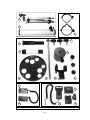
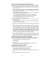
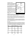
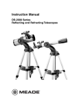
Fig. 1: Parts included in the Meade Model 4504 Giftbox.
page 4
16
PART ONE: The Basics
LESSON 1: Unpacking and Assembly
As you unpack your telescope, carefully note the following parts. The bolded numbers
in parentheses on this page refer to the photos on page 4.
Telescope Assembly
• Equatorial mount (1) with a pre-attached heavy duty, continuously
adjustable aluminum tripod with leg braces
• 3 tripod leg lock knobs (7)
• Complete optical tube assembly (2) including a 4.5" (114mm) diameter
primary mirror with dust cover and a 0.965" rack-and-pinion focuser with
dust cap
• 2 Cradle rings (3) with attached lock knobs
• Counterweight (8) and counterweight shaft (9)
• 5 x 24 viewfinder with rubber eyecup (5) and viewfinder bracket (10)
Motor Assembly
• Dual electronic motor drive assembly: The Right Ascension (R.A.)
electronic motor drive (12) has a connector for the battery pack, marked
"15v." The Declination (Dec) electronic motor drive (13) has a connector
for the Starfinder handbox, marked "HBX." The motors are connected
with a coiled cord.
• Starfinder handbox (14)
• Battery pack (16) and battery pack case (15) with adhesive backing
Accessories
• 3 Eyepieces (11) (0.965" optical diameter): SR 4mm, H 12.5mm,
H 25mm
• 3x Barlow lens (4)
• Accessory shelf with mounting knob (6)
• 2 Hex Keys, 1.5mm, 5mm (not depicted)
• Astronomical software (not depicted)
You will need a #1 or #2 Phillips screwdriver to assemble this telescope.
Key to the photos, Fig. 1, page 4.
1. Tripod assembly with equatorial mount
2. Optical tube
3. Cradle rings
4. 3x Barlow lens
5. Viewfinder tube
6. Accessory shelf
7. Tripod leg adjustment knobs
8. Counterweight
9. Counterweight shaft
10. Viewfinder bracket
11. Eyepieces
12. R.A. motor drive
13. Dec motor drive
14. Starfinder handbox
15. Battery pack case
16. Battery pack
page 5
7
6
8
5
4
3
2
9
15
10
1
14
11
16
12
13
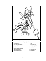
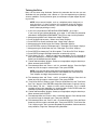
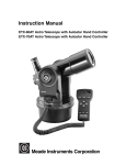
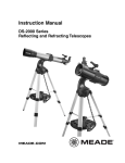
Fig. 2a: The Meade Model 4504 4.5" Equatorial Reflecting Telescope.
Key to Figures 2a, 2b, and 2c
1. Equatorial mount
16. Latitude adjustment knob
2. Optical tube assembly
17. Focuser, Focus knobs
3. Cradle rings
18. Eyepiece thumbscrew
4. Viewfinder bracket
19. Eyepiece
5. Viewfinder rubber eyepiece
20. Cradle ring lock knobs
6. 5 x 24 viewfinder
21. Optical tube saddle plate
7. Viewfinder bracket thumbscrews
22. Dec motor drive assembly
8. Telescope front dust cover
23. Latitude lock
9. Dec setting circle
24. Azimuth lock
10. Counterweight
25. R.A. motor drive assembly
11. Counterweight shaft
26. R.A. lock
12. Safety washer/thumbscrew
27. Dec lock
13. Counterweight lock
28. Tripod legs brace support
14. Latitude dial
29. Tripod legs lock knobs
15. R.A. setting circle
30. Accessory shelf
page 6
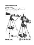
19
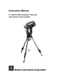
NOTE: The coiled cord that
connects to the two motor
drives has been omitted
from the illustration for the
sake of clarity.
18
20
21
17
20
27
26
22
23
25
24
Fig. 2b: The Meade Model 4504 4.5" Equatorial Reflecting Telescope.
28
28
29
30
29
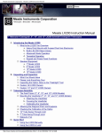
Fig. 2c: The Meade Model 4504 4.5" Equatorial Reflecting Telescope.
page 7
How to Assemble Your Telescope
The giftbox contains the optical tube assembly and the tripod with the equatorial
mount. The accessories are located within compartments custom-cut into the styrofoam block inserts. Refer to Figures 1, 2a, 2b, and 2c for images of the parts and the
overall assembly of the 4504 telescope.
Leg lock
knob
Threaded
hole
Sliding
inner leg
Fig. 3: Tripod leg lock
knob.
1. Remove the components from the giftbox: Remove and identify the telescope’s
standard equipment. For a listing of parts that are included in the giftbox, see
pages 4 and 5. When removing the tripod from the giftbox, hold the assembly
parallel (horizontal) to the ground or the inner tripod leg extensions will slide out
as they are not locked in place.
2. Install the lock knobs on the tripod: Place the tripod in a horizontal position on
the floor before performing this step. The three tripod lock knobs (7, Fig. 1) have
been removed from the bottom section of each tripod leg to insure safe arrival of
the tripod assembly. To install, thread each tripod lock knob into the threaded hole
located at the right side of each of the three gray-colored castings at the bottom
of each tripod leg. See Fig. 3, and 29, Fig. 2c. Tighten the tripod lock knob to a
"firm feel" only to avoid damage to the tripod caused by overtightening.
3. Stand the tripod: Hold the mount for support (the mount will be loose) and stand
the tripod in a vertical position. Slide the cardboard sheath upward to allow it to
come free when the tripod legs are spread out during the next step.
4. Adjust the tripod legs. Spread the tripod legs as far as they will open, so that the
leg braces (28, Fig. 2c) are taut. Should one of the leg braces slip out of the center
triangle fastener, reposition the brace and slide it back into the triangle fastener.
Fig. 4: Accessory
shelf installation.
Lock
knob
Pin
Fig. 5: Counterweight
and pin.
Thread shaft
into base
Fig. 6: Attach
counterweight
assembly to the
mount.
5. Attach the accessory shelf to the tripod: Remove the mounting knob from the
round accessory shelf (6, Fig. 1). Place the accessory shelf on top of the center
triangle leg brace fastener so that the threaded stud protruding from the bottom of
the shelf (Fig. 4) passes through the hole in the center of the triangle fastener.
Next, thread the mounting knob shaft into the threaded stud. Tighten to a firm feel.
6. Attach the counterweight to the counterweight shaft: Look through the hole in
the counterweight and note the pin blocking the hole (Fig. 5). Tilt the
counterweight slightly and the pin moves out of position, clearing the hole. If the
pin does not move, slightly unscrew the counterweight lock knob (Fig. 5) until the
pin moves. Holding the counterweight (8, Fig. 1) firmly in one hand, tilt the
counterweight to move the pin from the hole and slip the counterweight onto the
counterweight shaft (9, Fig. 1). Tighten the counterweight lock knob (Fig. 5) to a
firm feel.
7. Attach the counterweight assembly to the mount: Attach the counterweight
shaft assembly by supporting the counterweight firmly in one hand, while
threading the counterweight shaft into the base (Fig. 6) of the Declination axis of
the telescope’s equatorial mount with the other. Once firmly attached, loosen the
counterweight lock knob, slide the counterweight to the midpoint of the
counterweight shaft, and re-tighten the lock knob firmly in place (Fig. 5).
NOTE: If the counterweight ever slips, the secured threaded safety
washer/knob (12, Fig. 2a) prevents the counterweight from sliding entirely
off the shaft. The safety washer/knob is pre-attached at the factory. Make
sure that this safety washer/knob always remains in place.
page 8
1
2
1
3
4
5
Fig. 7: Attach cradle
rings to the saddle plate
with attachment screws.
1. Threaded screw hole
(saddle plate)
2. Saddle plate
3. Cradle ring
4. Threaded screw hole
(cradle ring)
5. Attachment screw
Eyepiece
Focuser
Thumbscrew
8. Tilt the assembly: Unlock the R.A. lock (26, Fig. 2b) and the Dec lock (27, Fig.
2b) so that the telescope turns freely on both axes. Tilting these axes makes it
easier for you to perform the following steps. Turn the latitude adjustment knob
(16, Fig. 2a) until approximately 1 1/2 inches of thread is showing. This will adjust
the equatorial mount (1, Fig. 2a) to a comfortable angle for tube attachment.
9. Attach the cradle rings to the saddle plate: Remove the attachment screws
from the saddle plate (these screws come attached in the threaded screw holes of
the saddle plate, 1, Fig. 7). Position the threaded screw hole of a cradle ring (4,
Fig. 7) under one of the threaded screw holes of the saddle plate (1, Fig. 7).
Thread one of the attachment screws (5, Fig. 7) through the bottom side of the
cradle ring and through the saddle plate, tightening it with the provided 5mm hex
wrench (so that it is only "fingertight," that is, just loose). Repeat for the second
cradle ring. Remove the cradle ring lock knobs (20, Fig. 2b) and open the cradle
rings.
10. Position optical tube: While firmly holding the optical tube (2, Fig. 2a), position it
onto the cradle rings (3, Fig. 2a) with the mid-point of the optical tube’s length lying
roughly in the center of the saddle plate. Point the tube so that the front end (this
end comes shipped with the dust cover (8, Fig. 2a) over it) is oriented as depicted
in Fig. 2a. Then close the cradle rings (3, Fig. 2a) over the optical tube and loosely
tighten one of the cradle ring lock knobs (20, Fig. 2b) just to hold the tube in place
so you can perform the next step of this procedure.
11. Secure the optical tube: Tighten the cradle ring attachment hex screws to a firm
feel. Then tighten both cradle ring lock knobs (20, Fig. 2b) to a firm feel; do not
overtighten these knobs as you may wish loosen them frequently in order to rotate
the optical tube and position the eyepiece (19, Fig. 2b) in a more comfortable
observing position. This adjustment may be performed several times in one
observing session, if so desired.
12. Attach viewfinder: The viewfinder holder has two restrained screws, i.e., they
cannot be removed from the holder. Position the two screws over the threaded
holes in the viewfinder mounting plate and tighten the screws using a #1 or #2
Phillips screwdriver. It does not matter which way you orient the holder lengthwise.
Loosen the viewfinder's thumbscrews (7, Fig. 2a), but do not remove them.
Remove the viewfinder tube's rubber eyecup (5, Fig. 2a) and slide the tube (6, Fig.
2a) through the bracket rings of the holder. Then center the tube by adjusting the
thumbscrews (7, Fig. 2a) on each bracket ring. Re-attach the eyecup. Make sure
that the viewfinder is oriented so that the rubber eyecup is pointing away from front
end of the optical tube (5, Fig. 2a).
13. Insert the eyepiece: Lift to remove the dust cap from the focuser assembly (17,
Fig. 2b). Put the dust cap aside in a safe place and replace it when you have
finished observing to protect the eyepiece assembly. Loosen the eyepiece
thumbscrews (18, Fig. 2b) and insert the H 25mm eyepiece (Fig. 8) into the
focuser. Tighten the focuser thumbscrews to secure the eyepiece.
14. Adjust the height of the tripod: Adjust the height of the tripod by loosening the
tripod lock knobs (29, Fig. 2c) and extending the sliding inner section of each
tripod leg to the desired length; then tighten each knob. Adjust the tripod to a
height that is comfortable for viewing.
Fig. 8: Insert eyepiece
into the focuser
assembly.
Lesson 5 presents a procedure that explains how to attach the motor drive
assemblies. However, that procedure is not necessary at this time. The following
lesson demonstrates how to balance your telescope.
page 9
LESSON 2: Balancing the Telescope
Dec
Lock
R.A.
Lock
Fig. 9a: Balancing
the telescope: the
axes locks.
Counterweight shaft
parallel to floor
In order for the telescope to be stable on the tripod and also for it to move smoothly,
it must be balanced. To balance the telescope, you will unlock the Right Ascension or
R.A. lock (26, Fig. 2b and Fig. 9a). When this axis is unlocked, the telescope pivots
more or less horizontally on the mount. This is called the R.A. axis. Later in the procedure, you will also unlock the Declination or Dec lock (27, Fig. 2b and Fig. 9a).
When unlocked, the telescope pivots more or less vertically on the mount. This is
called the Dec axis. Most of the motion of the telescope takes place by moving about
these two axes, separately or simultaneously. To obtain a fine balance of the telescope, follow the method below:
1. Firmly hold the optical tube secure so that it cannot accidentally swing freely.
Loosen the R.A. lock (26, Fig. 2b). The optical tube now turns freely about the
R.A. axis. Rotate the telescope so that the counterweight shaft (11, Fig. 2a) is
parallel (horizontal) to the ground (Fig. 9b).
2. Unlock the counterweight lock knob (13, Fig. 2a) and slide the counterweight (10,
Fig. 2a) along the counterweight shaft until the telescope remains in one position
without tending to drift down in either direction. Then re-tighten the counterweight
lock knob (13, Fig. 2a), locking the counterweight in position.
3. Again, hold onto the optical tube so that it cannot accidentally swing freely. Lock
the R.A. lock (26, Fig. 2b), and unlock the Dec lock (27, Fig. 2b). The telescope
now is able to move freely about the Dec axis. Loosen the cradle ring lock knobs
(20, Fig. 2b) so that the main tube slides easily back and forth in the cradle rings.
Move the main tube in the cradle rings until the telescope remains in one position
without tending to drift down in either direction. Re-lock the Dec lock (27, Fig. 2b).
The telescope is now properly balanced on both axes. Next, the viewfinder must be
aligned.
Fig. 9b: Balancing
the telescope.
LESSON 3: Aligning the Viewfinder
The wide field of view of the 5 x 24mm viewfinder provides an easier way to initially
sight objects than the main telescope's eyepiece, which has a much narrower field of
view. If the 5 x 24 mm viewfinder (6, Fig. 2a) is not already attached to the telescope
tube assembly, follow the procedure described in Lesson 1, step 7.
In order for the viewfinder to be functional, it must be aligned to the main telescope,
so that both the viewfinder and main telescope point at the same position in the sky.
This alignment makes it easier to find objects – first locate an object in the wide-field
viewfinder, then look into the eyepiece of the main telescope for a detailed view.
To align the viewfinder, follow these steps. Perform steps 1 through 4 during the daytime; perform step 5 at night.
1. Remove the telescope front dust cover (8, Fig. 2a).
2. If you have not already done so, insert the low-power H 25mm eyepiece (19, Fig.
2b) into the focuser of the main telescope. See Lesson 1, step #11.
3. Unlock the R.A. lock (26, Fig. 2b) and the Dec lock (27, Fig. 2b) so that the
telescope turns freely on both axes. Then point the main telescope at some welldefined and stationary land object (e.g., the top of a telephone pole) at least 200
yards distant and center the object in the telescope's eyepiece. Re-tighten the R.A
and Dec locks.
4. Look through the viewfinder and loosen or tighten, as appropriate, one or more of
the viewfinder bracket ring thumbscrews (7, Fig. 2a) until the viewfinder’s
crosshairs are precisely centered on the object you previously centered in the
main telescope's eyepiece.
page 10
NEVER point the telescope directly at or near the Sun at any time!
Observing the Sun, even for the smallest fraction of a second, will
result in instant and irreversible eye damage, as well as physical
damage to the telescope itself.
5. Check this alignment on a celestial object, such as a bright star or the Moon, and
make any necessary refinements, using the method outlined above in steps 3 and 4.
With this alignment performed, objects first located in the wide-field viewfinder will also
be centered in the main telescope’s field of view. You are now ready to make your first
observations with your telescope.
NOTE: The viewfinder and telescope present an upside-down image.
LESSON 4: Observing by Moving the Telescope Manually
This method describes how to make observations by manually moving the telescope.
IMPORTANT
NOTE:
Whenever you
move your telescope, either manually or with
Starfinder, position
the levers of the
R.A. and Dec locks
so that they point
upwards (see Fig.
10). An incorrectly
positioned lever
may strike and
damage another
piece of the telescope assembly
while the telescope
is moving.
After the telescope is assembled and balanced as described previously, you are ready
to begin manual observations. View easy-to-find terrestrial objects such as street
signs or traffic lights to become accustomed to the functions and operations of the telescope. For the best results during observations, follow the suggestions below:
•
When you wish to locate an object to observe, first loosen the telescope’s R.A.
lock (26, Fig. 2b) and Dec lock (27, Fig. 2b). The telescope can now turn freely on
its axes. Also unlock the Azimuth lock (24, Fig. 2b). Unlock each axis separately
and practice moving your telescope. Then practice with two or more unlocked
axes at the same time. It is very important to practice this step to understand
how your telescope moves, as the movement of an equatorial mount is not
intuitive.
•
Use the aligned viewfinder to sight-in on the object you wish to observe. When the
object is centered in the viewfinder’s crosshairs, re-tighten the R.A. and Dec locks.
•
A telescope’s eyepiece magnifies the image formed by the telescope’s main
optics. Each eyepiece has a focal length, expressed in millimeters, or “mm.” The
smaller the focal length, the higher the magnification. For example, an eyepiece
with a focal length of 4mm has a higher magnification than an eyepiece with a
focal length of 25mm. See "APPENDIX A," page 38 for more information.
Low-power magnification eyepieces offer a wide field of view, bright, high-contrast
images, and relief of eye strain during long observing sessions. To observe an object
with a telescope, always start with a low power eyepiece such as the H 25mm
supplied with the 4504. When the object is centered and focused in the eyepiece,
switch to a higher power eyepiece to enlarge the image as much as practical for
prevailing viewing conditions.
NOTE: Viewing conditions vary widely from night-to-night and site-to-site.
Turbulence in the air, even on an apparently clear night, can distort images.
If an image appears fuzzy and ill-defined, back off to a low-power eyepiece
for a more well-resolved image.
Point
lever
upwards
Fig. 10: Correctly
positioned lever.
•
The Barlow lens included with your telescope triples the eyepiece magnification.
See "APPENDIX A," page 38 for more information.
•
Once centered, an object can be focused by turning one of the knobs of the
focusing mechanism (17, Fig. 2b). Notice that when observing astronomical
objects, the field of view begins to slowly drift across the eyepiece field. This
motion is caused by the rotation of the Earth on its axis. Objects appear to move
through the field more rapidly at higher powers. See "APPENDIX B," page 39, for
detailed information. Lesson 6 will explain how you can counteract the drift in the
field of view.
page 11
13
12
9
10
5
11
4
6
1
2
3
7
8
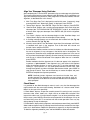
Fig. 11: Motor drive system assembly.
Key to Figure 11
1. R.A. Worm Shaft
7. LED
2. (R.A. Axis) Plastic Adapter
8. R.A. Motor Drive
3. Aluminum Shaft
9. Handbox (HBX) Port
4. Set Screw
10. Dec Motor Drive
5. Circular Housing containing
11. R.A. Lock
12. Dec Worm Shaft
notched plastic shaft
13. Set Screws
6. Battery Pack Connector
page 12
Observe the World Around You
Practice observing during the day, when it is easier to become familiar with the controls of your telescope.
1. Loosen the telescope’s R.A. lock (26, Fig. 2b) and Dec lock (27, Fig. 2b).
2. Move your telescope to observe distant street signs, mountains, trees, and other
structures. Use your viewfinder to to help site-in an object.
3. When the object is centered in the viewfinder’s crosshairs, remember to re-tighten
the R.A. and Dec locks.
4. Center the object in your eyepiece. Practice focusing with your eyepieces.
5. Once you get a feel for how your telescope moves and focuses, try to view
something more challenging, like a bird or a distant moving train.
LESSON 5: Observing Using Starfinder's Arrow Keys
Before you can observe using Starfinder's Arrow keys, the motor drive assemblies
and the Starfinder handbox must be attached to the telescope.
Motor Drive System and Starfinder Handbox Installation
To attach the Electronic Motor Drive System to the telescope, follow this procedure:
1. Locate the plastic adapter (2, Fig. 11) on the R.A. axis (1, Fig. 11). Note the
aluminum shaft (3, Fig. 12a) inside the adapter and the four small protrusions (2,
Fig. 12a) on the adapter's circular edge.
1
2
2. Locate the components of the R.A. motor drive (8, Fig. 11). Note the notched
plastic shaft (6, Fig. 12b) inside the circular housing on the side of the motor drive.
Also note the four small recesses (5, Fig. 12b) inside this housing.
2
3
Fig. 12a: Plastic adapter
assembly.
1. Plastic adapter
2. Protrusions
3. Aluminum shaft
4
6
Fig. 12b: Motor drive
assembly.
4. Motor drive
5. Recesses
6. Notched shaft
3. Attach the R.A. motor drive to the R.A. axis: Align and slide the notch (6, Fig.
12b) of the plastic shaft of the R.A. motor drive over the aluminum shaft (3, Fig.
12a) inside the plastic adapter on the R.A. axis. Orient the R.A. motor drive box
as depicted in 8, Fig. 11.
4. Rotate the R.A. motor drive until you feel the four protrusions (2, Fig. 12a) on the
plastic adapter slide into the four matching recesses (5, Fig. 12b) inside the motor
drive.
5
5
NOTE: The R.A. motor drive has a connector for the battery pack that is
marked "15v."
5. Tighten the set screws: Tighten the two set screws (4, Fig. 11) to a firm feel only
with the supplied 1.5mm hex key. The set screws come attached to the motor
drive.
6. Repeat the process to attach the Dec electronic motor drive to the Dec axis (10,
Fig. 11). Orient the Dec motor drive box as depicted in 10, Fig. 11.
7. Attach Starfinder: Plug Starfinder’s coiled cord into the connector (9, Fig. 11) on
the Dec motor box.
8. Install batteries: Install ten (user-supplied) AA-size batteries into the separate
battery pack and plug the battery pack into the connector (16, Fig. 1) on the R.A.
motor box (6, Fig. 11). The battery pack case has a strip of adhesive attached to
it. Remove the protective covering from the adhesive and attach the case to the
tripod, if so desired.
The Electronic Motor Drive System is now ready for operation.
page 13
Activate the Arrow Keys
NOTE:
Press and hold the
Up Arrow key to
speed up the scroll
speed of the display
or press and hold the
Down Arrow key to
slow down the scroll
speed. When the
display is scrolling at
a speed that is
comfortable for
reading, release the
key.
This procedure describes how to activate
Starfinder's Arrow keys:
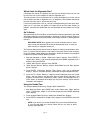
1. After Starfinder's cord is plugged in and the
batteries are installed, a copyright message
lights on the Starfinder LCD display (1, Fig.
13).
2. A message warning not to look at the Sun
scrolls across the display. Press the key
prompted by Starfinder to acknowledge that
the Sun warning has been read and
understood.
3. Press the ENTER (2, Fig. 13) key repeatedly
until "Country/State" appears on the display.
(Ignore the prompts requesting Date and
Time – these functions will be explained in
Lesson 7, but are not necessary for the
current lesson.)
1
4
2
3
5
8
7
6
9
Fig. 13: The Starfinder handbox.
4. Use the Scroll keys (6 and 7, Fig. 13) to cycle through the database of countries,
states, and provinces. Press ENTER when the correct location displays.
NOTE: Starfinder
only prompts you to
enter Country (or
State) and City as
described in steps 3,
4, and 5, the first time
it is activated. These
prompts do not
appear again, unless
you reset Starfinder
(see "RESET," page
32).
However, if you need
to enter this
information (e.g., you
change your
geographic location),
you need not perform
a Reset, which
erases user entered
data, such as
Landmarks and User
Objects. You can
change the location
information by using
the Site option of the
Setup menu. See
"SITE," page 32, for
detailed information.
5. Starfinder then prompts you to enter the nearest city (listed alphabetically) to the
observing site. Use the Scroll keys to cycle through the database of cities. Press
ENTER when the correct city appears on screen. The display then reads "Align:
One Star." You now can use Starfinder's Arrow keys to move the telescope to
observe.
NOTE: If you go past the "Align: One Star" (or any other menu display you
wish to select), press MODE to return to the previous display(s).
6. Press the Arrow keys (5, Fig. 13) to slew (move) the telescope up, down, right, or
left. You can slew (move) the telescope at different speeds.
Slew Speeds
Starfinder has seven slew (move) speeds. Each speed has been calculated to accomplish specific functions. Pressing the Speed/? key (8, Fig. 13) briefly changes the slew
speed, which is shown briefly on Starfinder’s display as the key is pressed. Each press
decreases the slew speed down one level and then cycles back to the fastest speed.
NOTE: Pressing the Speed/? key briefly changes the slew speed. Holding
down the Speed/? key longer (one to two seconds) accesses the Help
function.
The seven available speeds are:
Speed 1
Max = 240 x sidereal (60 arc-min/sec or 1°/sec)
Speed 2
0.5° =
Speed 3
64X =
120 x sidereal (30 arc-min/sec or 0.5°/sec)
64 x sidereal (16 arc-min/sec or 0.27°/sec)
Speed 4
32X =
32 x sidereal (8 arc-min/sec or 0.13°/sec)
Speed 5
16X =
16 x sidereal (4 arc-min/sec or 0.067°/sec)
Speed 6
8X =
8 x sidereal (2 arc-min/sec or 0.033°/sec)
Speed 7
2X =
2 x sidereal (0.5 arc-min/sec or 0.008°/sec)
page 14
Speed 1: Fastest speed to move the telescope from one point in the sky to another.
Speeds 2 or 3: Best used for the rough centering of an object in the eyepiece.
Speeds 4 or 5: Enables the centering an object in the field of a low-to-moderate power
eyepiece such as the standard H 25mm
Speeds 6 or 7: Best used for the fine centering of an object in the field of view of a
high-power eyepiece such as the standard SR 4mm.
Observe the Moon
Point your telescope at the Moon (note that the Moon is not visible every night) and
practice using the Arrow keys and the slew speeds to view different features. The
Moon contains many interesting features, including craters, mountain ranges, and
fault lines. The best time to view the Moon is during its crescent or half phase. Sunlight
strikes the Moon at an angle during these periods and adds a depth to the view. No
shadows are seen during a full Moon, causing the overly bright surface to appear flat
and rather uninteresting. Consider the use a neutral density Moon filter when observing the Moon. Not only does it cut down the Moon's bright glare, but it also enhances
contrast, providing a more dramatic image.
NOTE: Do not look through the telescope's eyepiece or viewfinder while it
is rapidly moving. Children should always have adult supervision while
observing.
LESSON 6: Tracking Objects
As the Earth rotates beneath the night sky, the stars appear to move from East to
West. The speed at which the stars move is called the sidereal rate. You can setup
your telescope to move at the sidereal rate so that it automatically tracks the stars and
other objects in the night sky. The tracking function automatically keeps an object
more or less centered in the telescope’s eyepiece.
To automatically track objects, you must first Polar align the telescope and then select
"Targets: Astronomical" from the Starfinder Setup menu.
To Polar Align the Telescope:
Fig. 14: Latitude dial.
Fig. 15: Dec setting
circle.
1. Level the mount, if necessary, by adjusting the length of the three tripod legs.
2. Release the Azimuth lock (24, Fig. 2b) of the tripod, so that the entire telescope
may be rotated in a horizontal direction. Rotate the telescope until it points due
North. Then re-tighten the lock. Use a compass or locate Polaris, the North Star
(see Fig. 31, page 40), as an accurate reference for due North.
3. Determine the latitude of your observing location. See "APPENDIX D: HELPFUL
CHARTS," page 43, for a list of latitudes of major cities around the world. Release
the latitude lock (23, Fig. 2b) and tilt the telescope mount with the latitude
adjustment knob (16, Fig. 2a) so that the pointer indicates the correct latitude of
your viewing location on the latitude scale (Fig. 14). Re-tighten the latitude lock
(23, Fig. 2b).
4 Unlock the Dec Lock (27, Fig. 2b). Rotate the Optical Tube Assembly until the Dec
setting circle pointer (Fig. 15) points at 90°.
5. If steps 1 through 4 above were performed with reasonable accuracy, your
telescope is now sufficiently well-aligned to Polaris, the North Star, for you to begin
making observations.
Once the mount has been Polar-aligned as described above, the latitude angle need
not be adjusted again, unless you move to a different geographical location (i.e., a different latitude). The only Polar Alignment procedure that needs to be performed each
time you observe is to point the telescope due North, as described in step 2 above.
IMPORTANT NOTE: For almost all astronomical observing requirements,
approximate settings of the telescope’s latitude and azimuth axis are
acceptable. Do not allow undue attention to precise Polar Alignment of the
telescope to interfere with your basic enjoyment of the instrument.
page 15
Observe a Star using the Automatic Tracking Feature
In this example, Starfinder's Arrow keys are used to find a star, and then Starfinder's
tracking capability automatically keeps the star centered in your telescope's eyepiece.
1. If you have just completed Lesson 5, Starfinder's display now reads "Align: One
Star." Go to Step 2.
If you have not used Starfinder yet or have just plugged it into the HBX port,
perform the procedure described in "ACTIVATE THE ARROW KEYS," page 14.
Then go to Step 2 of this procedure.
If you have been using Starfinder to perform other functions and the display does
not read "Align: One Star," follow these steps:
a. Press MODE (3, Fig. 13) repeatedly until "Select Item: Object" displays.
b. Press the Scroll Up key (6, Fig. 13) once. "Select Item: Setup" displays.
c. Press ENTER (2, Fig. 13). "Setup: Align" displays. Go to Step 3.
2. Press MODE (3, Fig. 13). "Setup: Align" displays.
3. Press the Scroll Down key repeatedly until "Setup: Targets" displays. Press
ENTER (2, Fig. 13).
4. "Targets: Terrestrial" displays. Press one of the Scroll keys once (6 or 7, Fig. 13).
"Targets: Astronomical" now displays.
5. If you have not already done so, Polar align your telescope as described on page
15.
6. Use the Arrow keys (5, Fig. 13) to locate a bright star in the night sky. Use the
viewfinder to help line up on the star. You may choose any unobstructed, bright
star for the purposes of this example. Use Starfinder's Arrow keys to center the
star in the eyepiece. Once the star is centered, press ENTER to select
"Astronomical." The telescope's tracking motors then engage. It may take the
tracking motors several seconds to begin tracking. When they do, it may be
necessary to once again center the star in the eyepiece. The tracking motors will
then keep the star you have chosen in the center of the eyepiece.
7. Press and hold the ENTER key for a few seconds and then release to stop
tracking. You may repeat the procedure, if so desired, to locate another star or
object using the Arrow keys. Then press ENTER to re-engage the tracking motors.
LESSON 7: Using Starfinder's GO TO Capabilities
This lesson describes how to make observations using various Starfinder features and
menus. But before you can use Starfinder's GO TO capabilities, you must first:
•
Learn how Starfinder's keys move through the menus
•
Initialize Starfinder
•
Train the drive
•
Polar align the telescope, if you have not already done so (see Lesson 6)
•
Select "Align: One Star" from Starfinder's menus
Moving Through Starfinder’s Menus
Starfinder's menus are organized for quick and easy navigation.
•
Press ENTER to go deeper into Starfinder menu levels.
•
Press MODE to move back toward the top menu level.
•
Press the Scroll keys to move up and down through the options available for each
level.
•
Press the Arrow keys to enter characters and digits.
page 16
Initializing Starfinder
This exercise describes how to initialize Starfinder.
Initialization is a procedure that enables Starfinder to operate correctly. When you first
use Starfinder, it doesn't yet "know" the location of the observing site or the time or
date of the observation session. During the Initialization procedure, you will enter this
information. Starfinder then uses the information to calculate the location of celestial
objects (such as stars and planets) and to move your telescope correctly for various
operations.
NOTE: Normally, you will enter the Time and Date at the beginning of each
observing session, but you will only perform the full Initialization procedure
(i.e., entering the Location information as well as the Time and Date) the
first time you use Starfinder or after performing a Reset. Fig. 16 depicts an
example of Starfinder Initialization procedure.
NOTE: See "STARFINDER CONTROLS," page 23, for a detailed
description of Starfinder's Keys.
1. Make sure that the telescope is assembled correctly, and that the batteries and the
motor drives are installed as described previously.
2. Plug Starfinder's cord into the HBX port, as previously described, or if Starfinder
is already plugged in, unplug it briefly and then plug it back in again.
3. A copyright message lights on Starfinder’s LCD display and a message warning
not to look at the Sun scrolls across the display. Press the key prompted by
Starfinder to acknowledge the message has been read and understood.
4. The Getting Started menu displays a scrolling message with two choices:
a. Press and hold down the Speed/? key (8, Fig. 13) for about 2 seconds for
information on Starfinder functions and controls. When finished, press MODE
(3, Fig. 13) to exit Help, or,
b. Press ENTER (2, Fig. 13) to bypass the Help tutorial and continue with
Initialization.
5. Starfinder then prompts you to enter the current date:
a. To enter numbers, press either the Up or Down Arrow key (5, Fig. 13) to scroll
through numbers 0 through 9. After the desired number is displayed, use the
Right Arrow key (5, Fig. 13) to move the cursor from one number to the next
in the day display (or use to Left Arrow key to move in the other direction
across the display, if necessary).
b. Use the Right Arrow key (5, Fig. 13) to move the cursor to the month. Use the
Scroll keys (8, 9, Fig. 13) to cycle through the list of months. When the current
month is displayed, use the Right Arrow (5, Fig. 13 to move the cursor to the
year.
c. Use the Up and Down Arrow keys to enter all four digits of the current year.
Use the Right Arrow key to move the cursor from one number to the next.
d. Press ENTER (2, Fig. 13) when the entire date has been entered.
6. Starfinder then prompts you to enter the current time. Use the Up and Down Arrow
keys to enter digits and the Right and Left Arrow keys move the cursor across the
screen as described in the previous step. Enter the current time (use a "0" for the
first digit if less than 10). Use the Up Arrow key (7, Fig. 13) to scroll through "AM,"
"PM,'" or "blank." The "blank" option selects the 24-hour (i.e., military time) clock.
Then press ENTER to start the clock.
NOTE: When multiple choices are available within a menu option, the
option that is currently selected is usually displayed first and highlighted by
a right pointing arrow (>).
page 17
7. Starfinder then prompts you to enter the status of Daylight Savings Time. Press
one of the Scroll keys to toggle between the YES/NO settings. Select the desired
setting by pressing ENTER.
NOTE: Daylight Savings Time may be referred to by a different name in
various areas of the world.
8. If you have previously entered the Country/State and City of your observing site
(as described in "ACTIVATE THE ARROW KEYS," page 14), go to step 9. If you
have not entered this information, perform the following steps:
a. Starfinder prompts you to enter the Country or State (listed alphabetically) of
the observing site. Use the Scroll keys to cycle through the database of
countries, states, and provinces. Press ENTER when the correct location
displays.
b. Starfinder then prompts you to enter the nearest city (listed alphabetically) to
the observing site. Use the Scroll keys to cycle through the database of cities.
Press ENTER when the correct city appears on screen.
NOTE: Starfinder only prompts you to enter Country/State and City the first
time it is activated. These prompts do not appear again, unless you reset
Starfinder (see "RESET," page 32). However, if you change your
geographic location, you can change the location information by using the
Site option of the Setup menu. See "SITE," page 32, for detailed
information.
9. System Initialization is complete and the display reads "Align: One Star." After
performing the Initialization procedure, you MUST train your drive. Continue to
page 19.
Note:
The following parameters
are used in the example
depicted in Fig. 16:
Date: March 26, 2001
Time: 11:47 PM
Location: Irvine,
California
In this example, it is
assumed that the
Country/State and City
data has not yet been
entered into Starfinder.
(00) Meade (1.0)
STARFINDER
ENTER
ENTER
Initializing. . .
Enter Time:
08:00:00PM (default)
WARNING
LOOKING AT . . .
Press the
appropriate
key
Getting Started
For a Detailed...
1 (1X)
Multiple
Presses
(1X)
1 (3X)
Country/State
CALIFORNIA
ENTER
(1X)
ENTER
4 (4X)
Enter Date:
01-Jan-2000
Nearest City
ALAMEDA NAS
Multiple
Presses
7 (7X)
2 (2X)
PM (default)
(1X)
Nearest City
IRVINE
ENTER
Enter Time:
11:47:00PM
6 (5X)
(1X)
ENTER
Mar (2X)
2000 (4X)
Country/State
AFGHANISTAN
Daylight Savings
>NO
2001 (1X)
Enter Date:
26-Mar-2001
Fig. 16: Example of the Initialization procedure.
page 18
Setup
Align
Training the Drive
Next, train the drive using Starfinder. Perform this procedure the first time you use
Starfinder with your telescope, after a Reset, or if you are experiencing any pointing
accuracy problems. Training the drive gives your telescope a higher degree of pointing accuracy.
NOTE: Use a terrestrial object, such as a telephone pole or lamp post, to
train the drive. It is best to perform this procedure during the daytime.
Complete this exercise once every 3 to 6 months to maintain the highest
level of telescope pointing accuracy.
1. If you have just performed "INITIALIZING STARFINDER," go to step 2.
2.
3.
4.
5.
6.
7.
8.
9.
10.
11.
12.
If you have not yet initialized Starfinder, go to page 17 and follow the procedure
described in "INITIALIZING STARFINDER." Then go to to step 2 of this procedure.
Keep pressing MODE until "Select Item: Object" displays.
Press the Scroll Up key once. "Select: Item: Setup" displays.
Press ENTER to access the Setup menu. "Setup: Align" displays.
Keep pressing the Scroll Up key until "Setup: Telescope" displays.
Press ENTER to access the Telescope menu. "Telescope: Focal Length" displays.
Keep pressing the Scroll Down key until "Telescope: Train Drive" displays.
Press ENTER to choose the Train Drive option. "Train Drive: RA Train" displays.
Press ENTER to begin RA (Right Ascension or horizontal) training.
"Drive Setup: For this...." begins to scroll across the display. This is a reminder to
point your telescope at a terrestrial object. Press ENTER when the telescope is
pointing at the desired terrestrial object.
"Center reference object" displays. Center your target object using the Arrow keys.
When centered, press ENTER.
The telescope slews and "Press > until it is centered" displays. Press the Right
Arrow key until the target is centered again. Then press ENTER.
NOTE: If you pass the object when pressing the Arrow key, you cannot slew
the telescope back in the other direction. Press MODE until "Train Drive: RA
Train" displays and begin the procedure over again.
>
13. The telescope slews and "Press < until it is centered" displays. Press the Left
Arrow key until the target is centered again. Then press ENTER.
14. "Train Drive: RA Train" displays again. Press the Scroll Down key and "Train Drive:
Dec Train" displays. Press ENTER to begin Dec (Declination or vertical) training.
15. "Drive Setup: For this...." begins to scroll across the display. This is another
reminder to point your telescope at a terrestrial object. Press ENTER when the
telescope is pointing at the desired terrestrial object.
16. "Center reference object" displays. Center your target object using the Arrow keys.
When centered, press ENTER.
17. The telescope slews and "Press until it is centered" displays. Press the Up Arrow
key until the target is centered again. Then press ENTER.
18. The telescope slews and "Press until it is centered" displays. Press the Down
Arrow key until the target is centered again. Then press ENTER. "Train Drive: Dec
Train" displays again. You have now completed this procedure. Continue onto the
next procedure, "Align Your Telescope Using Starfinder."
>
page 19
Align Your Telescope Using Starfinder
After completing the "Train the Drive" procedure, align your telescope using Starfinder.
The fastest and easiest way to start observing with Starfinder's Go To capabilities is to
align your telescope using One-Star (Polar) Alignment. An alternate method, Two-Star
alignment, is described later in this manual.
1. With "Train Drive: Dec Train" displayed (or scroll to this menu, if necessary), keep
pressing MODE until "Select Item: Setup" is displayed. Press ENTER.
2. "Setup: Align" displays. Press ENTER. "Align: One Star" displays. Press ENTER.
3. "German North" displays and a scrolling message prompts you to Polar align your
telescope. See "TO POLAR ALIGN THE TELESCOPE," page 15, for a description
of how to Polar align your telescope. Press ENTER after you finish the alignment
procedure.
4. "Ctr. Polaris" displays and the telescope begins to slew. Starfinder beeps and
"Adjust Mount" displays after the telescope finishes slewing.
5. A scrolling message prompts you to unlock both the Latitude Lock (23, Fig. 2b)
and the Azimuth Lock (24, Fig. 2b).
6. Manually rotate (do NOT use Starfinder's Arrow keys!) the telescope until Polaris
is centered once again in the eyepiece. Then re-lock both the Latitude and
Azimuth Locks and press ENTER.
7. Starfinder then chooses another star from its database and the telescope slews to
the star for alignment. It may not appear in the field of view in the eyepiece. The
alignment star should be easily recognized and be the brightest star in the area of
the sky where the telescope is pointing. Use the Arrow keys to move the telescope
until the star is visible and centered in the eyepiece. When the star is centered,
press ENTER.
Another method to find the alignment star if it does not appear in the eyepiece is
to perform a "spiral search." If the alignment star is not visible in the eyepiece
when the telescope finishes its search, press GO TO and the telescope starts
slewing in a spiral pattern at a very slow speed around the search area. Look
through the eyepiece and when the object does become visible, press MODE to
stop the spiral search. Then use the Arrow keys to center the object and press
ENTER to complete the alignment procedure.
NOTE: Starfinder locates alignment stars based on the date, time, and
location entered. The alignment stars may change from night to night. All
that is required is for the observer to center the selected star in the eyepiece
when prompted.
Check Mount
It is possible for the 4504 telescope to move in such a way that the telescope tube
might interfere with the mount while slewing. Starfinder has a feature called "Check
Mount" to alert you of this possibility.
If "Check Mount" displays, inspect the assembly to see if it's moving in such a way that
the mount, tube, levers, motors, etc., might catch on or collide with each other. Also
inspect the cable to see if it might become tangled. If any of these possibilities seem
likely to occur, press MODE to abort the current operation of the telescope. If they do
not seem likely, press GO TO to continue with the current operation. Press any key
during slewing to stop the telescope.
If "Check Mount" displays during alignment, and interference seems likely, press MODE.
Select another alignment star by pressing one of the Scroll keys to select the next alignment star in the database. Repeat this procedure as necessary to align the telescope.
To abort the alignment procedure, press and hold MODE for about two seconds.
page 20
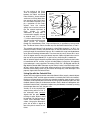
Which One’s the Alignment Star?
If Starfinder has chosen an alignment star that you are unfamiliar with, how can you
be sure if the star in your eyepiece is really the alignment star?
The rule of thumb is that an alignment star is usually the brightest star in that area of
the sky. When you view an alignment star in an eyepiece, it will standout dramatically
from the rest of the stars in that portion of the sky.
If you have an obstruction, such as a tree or a building blocking your view of the alignment star, or if you have any doubts at all about the star that has been chosen, no
problem. Just press the Scroll Down key and Starfinder will find another star to align
upon.
Go To Saturn
After performing the Train the Drive and the One-Star alignment procedures, the motor
drive begins operating and the telescope is aligned for a night of viewing. Objects in
the eyepiece should maintain their position even though the Earth is rotating beneath
the stars.
IMPORTANT NOTE: Once aligned, only use the Starfinder menus or Arrow
keys to move the telescope. Do not loosen the telescope locks, or move the
base manually, or alignment will be lost.
This exercise demonstrates how to select an object for viewing from Starfinder’s database, i.e., Saturn. Note that Saturn is not visible all year long and it may be necessary
for you to choose another object from Starfinder's database. However, the procedure
is identical to the one used for observing Saturn.
1. After the telescope is aligned, “Select Item: Object” displays. Press ENTER. If
“Select Item: Object” is not currently displayed, press MODE repeatedly until it
displays, then press ENTER.
2. “Object: Solar System” displays. Press ENTER.
3. “Solar System: Mercury” displays. Use the Scroll Down key until “Solar System:
Saturn” displays.
4. Press ENTER. “Calculating” displays. Then “Saturn” and a set of coordinates
displays. Saturn’s (and other planets’) coordinates change throughout the year.
5. Press GO TO. “Saturn: Slewing...” displays and the telescope slews until it finds
Saturn. You may need to use the Arrow keys to center Saturn precisely in the
eyepiece. Starfinder then automatically slews (moves) the telescope so that it
tracks Saturn (or whatever other object you may have chosen). Saturn remains
centered in the eyepiece.
Using the Guided Tour
This example demonstrates using “Tonight’s Best” Guided Tour.
1. After observing Saturn, press MODE twice so that “Select Item: Object” displays
again. If “Select Item: Object” is not currently displayed, press MODE repeatedly
until it displays.
2. Press the Scroll Down key twice. “Select Item: Guided Tour” displays.
3. Press ENTER. “Guided Tour: Tonight’s Best” displays. Press ENTER to select this
tour.
NOTE: If you wish to try out other Guided Tours, press the Scroll Down key
to scroll through other tour choices. When the tour you wish to select
displays, press ENTER.
page 21
4. “Tonight’s Best: Searching...” displays. After calculating, “Tonight’s Best: Jupiter”
displays.
NOTE: Different objects may be displayed on a tour list on any given night.
Press ENTER and then use the Scroll keys to display information about the object.
Press Mode to exit the information display. Press GO TO to move the telescope
to the object.
5. Press MODE to return to the Tour list. Press the Scroll keys to scroll through the
list. Press ENTER when you find the next object you wish to observe.
6. Press MODE and hold for about two seconds to leave the Guided Tour menu.
Some Observation Tips
•
Avoid touching the eyepiece while observing through the telescope. Vibrations
resulting from such contact will cause the image to move. Likewise, avoid
observing sites where ground-based vibrations may resonate the tripod. Viewing
from the upper floors of a building may also introduce image movement.
•
Allow your eyes a few minutes to become adapted to the dark before attempting
any serious astronomical observations. Use a red filtered flashlight to protect your
night vision when reading star maps or inspecting the components of the
telescope.
•
Avoid setting up the telescope inside a room and observing through an open
window (or worse yet, a closed window). Images viewed in such a manner may
appear blurred or distorted due to temperature differences between inside and
outside air. Also, it is a good idea to allow your telescope a chance to reach the
ambient (surrounding) outside temperature before starting an observing session.
•
Avoid viewing objects low on the horizon. Objects will appear better resolved with
far greater contrast when viewed higher in the sky. If images appear to “shimmer”
in the eyepiece, reduce eyepiece power until the image steadies. This condition is
caused by air turbulence in the upper atmosphere.
You have now completed all the Lessons for the basic operation of your 4504
telescope. All of Starfinder's features perform in the same way as the features
covered in Part 1. Practice these procedures so you can apply them to the
more advanced Starfinder menu features presented in Part 2 of this manual.
page 22
PART TWO: Starfinder Controls and Menus
This section describes how Starfinder operates, including:
•
Starfinder's controls
•
How to move through Starfinder's menus
•
Alignment setups
•
Starfinder's Menus
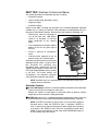
Control of the 4504 is through the operation of the standard-equipment Starfinder
handbox (Fig. 17). Nearly all functions of the telescope are accomplished with just a
few pushes of Starfinder’s buttons. Some of the major features of Starfinder are:
•
Automatically move the telescope to
any of the more than 1400 objects
stored in its database, or manually
enter coordinates of any celestial
object.
•
Take a guided tour of the best celestial
objects to view on any given night of
the year.
•
1
4
2
Access a glossary of astronomical
terms.
•
3
5
Calculate which eyepiece to use for
optimal viewing of a celestial object.
Starfinder provides control of virtually every
telescope function within a compact handbox. Starfinder has soft-touch keys
designed to have a positive feel. The LCD
(Liquid Crystal Display) is backlit with a red
LED (Light Emitting Diode) for easy viewing
in the dark. The backlit display, key
arrangement, and sequential database
make Starfinder extremely user-friendly.
8
7
6
9
Fig. 17: Starfinder controls.
NOTE: Starfinder does not require batteries; the telescope’s battery pack
supplies power to Starfinder.
Starfinder Controls
1
2-Line LCD Display: Provides an interface between Starfinder and the telescope.
Top line: lists the primary category or menu item.
Bottom line: contains a menu option or information about an object or subject,
depending on which function is being performed.
2
ENTER Key: Accesses, in a sequential manner, the next menu or data level in the
Starfinder database (see “HOW STARFINDER’S MENUS WORK,” page 26).
NOTE: If ENTER is pressed for two seconds or more and then released,
Starfinder emits a beep and “ENTER to Sync” is displayed. "ENTER to
Sync" is relevant only after the telescope has been aligned and is pointing
at an object. If the "ENTER to Sync" feature is accessed by mistake, press
MODE to return to the previous screen. See “HIGH PRECISION,” page 32
for more details about this feature.
page 23
3
MODE Key: Returns to the previous menu or data level in the Starfinder database
until the top level, “Select Item," is reached. The MODE key is similar to the
ESCAPE key on a computer.
NOTE: Pressing MODE while in the Select Item level moves Starfinder to
the topmost screen: "Select Item: Object."
NOTE: If MODE is pressed and held for two seconds or more, the following
information is then available using the Scroll keys (6 and 7, Fig. 17):
• Right Ascension and Declination coordinates
• Altitude and Azimuth coordinates
• Local Time and Local Sidereal Time (LST)
• Timer and Alarm Status
Press MODE again to return to the previous menu.
4
GO TO Key: Slews the telescope to the coordinates of the currently selected
object. While the telescope is slewing, the operation may be aborted at any time
by pressing any key except GO TO. Pressing GO TO again resumes the slew to
the object.
The GO TO key also allows you to perform a "spiral search." A spiral search is
useful when the telescope slews to an object, but that object is not visible in the
eyepiece after the telescope finishes it search. (This sometimes occurs during an
alignment procedure. See "ALIGN YOUR TELESCOPE USING STARFINDER,"
page 20.) Press GO TO when the slew is finished and the telescope starts slewing
in a spiral pattern at a very slow speed around the search area. Look through the
eyepiece and when the object does become visible, press MODE to stop the spiral
search. Then use the Arrow keys to center the object.
5
6
Arrow Keys: Slew the telescope in a specific direction (up, down, left, and right),
at any one of seven different speeds (speed selection is explained in “SLEW
SPEEDS,” page 14). The following functions are also available with the Arrow
keys:
• Data Entry: Use the Up and Down Arrow keys to Scroll through the letters of
the alphabet and numerical digits. The Down Arrow key starts with the letter "A"
and the Up Arrow key starts with the digit "9." Use the Left and Right Arrow keys
to move the blinking cursor left and right across the LCD display.
• Polar Alignment: Use the Left and Right Arrow keys to move the telescope.
The Left Arrow key rotates the telescope counterclockwise on the Right
Ascension axis, while the Right Arrow key rotates it clockwise.
Scroll
Keys: Access database options within a selected menu. The menu is
7
displayed on the first line of the screen. Options within the menu are displayed,
one at a time, on the second line. Press the Scroll keys to move through the
options. Press and hold a Scroll key to move quickly through the options.
The Scroll keys also scroll through the letters of the alphabet and numerical digits.
NOTE: The Scroll Down key and the Down Arrow key move forward through
the alphabet & digits (A to Z, 0-9) and the Scroll Up key and the Up Arrow
key move backward (Z to A, 9-0).
Press and hold the Up Arrow key to speed up the rate at which a message scrolls
across the display. Press and hold the Down Arrow key to slow down the scrolling
speed. When the display is scrolling at a speed that is comfortable for reading,
release the Scroll key.
page 24
8
Speed/? Key: Briefly pressing the Speed/? key cycles through the seven slew
speeds that move the telescope (see “Slew Speeds,” page 14).
NOTE: Pressing the Speed/? key briefly changes the slew speed. Holding
down the Speed/? key longer (one to two seconds) accesses the Help
function.
The Speed/? key also accesses the "Help" file. "Help" provides on-screen
information on how to accomplish whatever task is currently active.
Hold down the Speed/? key and then follow the prompts on the display to access
details of Starfinder functions in the Help feature. The Help system is essentially
an on-screen instruction manual.
If you have a question about a Starfinder operation (i.e., INITIALIZATION,
ALIGNMENT, etc.), hold down the Speed/? key and follow the directions that scroll
on the second line of the LCD screen. When a word appears in [brackets], press
ENTER to access the word in the Starfinder Glossary. A definition or more detailed
information is displayed. Press MODE to return to the scrolling Starfinder Help
display.
When satisfied with the Help provided, press MODE to return to the original
screen and continue with the chosen procedure.
9
Coil Cord: To operate, the Starfinder coil cord must be plugged into the HBX port
(9, Fig. 11) of the Dec motor box.
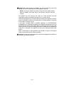
page 25
OBJECT
Select from over 1400 database objects and
press GO TO to move the telescope automatically to the
object and place it in the telescopic field of view.
SETUP
Quick, easy alignment
permits all telescope
operations with only
a 2-minute setup.
Select Item:
Object
Select Item:
Setup
UTILITIES
Calculate eyepiece
magnifications; set the
timer for an observing
session; or survey user
landmarks in 30-second
intervals.
Select Item:
Utilities
The Universe of
Starfinder
Select Item:
Event
EVENT
Access the time of
an astronomical
event, such as the
rising or setting
times of the Moon.
Select Item:
Guided Tour
GLOSSARY
Discover the world of astronomy
by alphabetically accessing
astronomical terms.
Select Item:
Glossary
GUIDED TOUR
Journey through the
universe as Starfinder
escorts you to the
best celestial objects
at your location.
Fig. 18: The Starfinder universe.
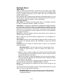
How Starfinder's Menus Work
It is important to understand that Starfinder's menu selections are set in a loop. This
means that pressing the Scroll Down key cycles down through all the available options
within a given category and then returns to the first option. The Scroll Up key cycles
up through the options in the opposite order. Note that this capability is a quick way to
get to an option that is near the bottom of the list. The following example demonstrates
this capability.
To navigate to the "Select Item: Setup" menu option when the "Select Item:
Object" menu is displayed:
1. Press the Scroll Down key four times or the Scroll Up key once.
The screen in Fig. 19 displays two lines of information.
The top line shows the current menu level. The second
line displays an option which may be selected within
that menu level. Some options are choices that select
the next menu level down. The Scroll keys move up and
down within the list of available options, showing one
option at a time.
ENTER
Select Item
Object
Select Item
Solar System
Fig. 19: Starfinder levels.
When the desired option is displayed on the second line, press the ENTER key to
choose that option and move down one menu level.
To leave a level (e.g., the wrong menu option is chosen), press the MODE key.
IMPORTANT NOTE: No matter how many menu levels of Starfinder are
traveled, each press of the MODE key moves up a level, until the top menu
level, "Select Item," is reached. Once in the Select Item level, press MODE
to return to the topmost available screen: "Select Item: Object."
Starfinder Navigation Exercise
To demonstrate how the Starfinder menu structure works, the following exercise calculates the Sunset time so an evening observing session can be planned.
page 26
NOTE: To perform an accurate calculation, Starfinder must be properly
initialized with the current date, time, and location of the observing site.
To enter the current date, time, and location information of your observing
site, see “ INITIALIZE STARFINDER” page 17, before proceeding with this
exercise.
To Calculate Sunset time:
1. Press the MODE key several times, until "Select Item: Object" displays.
2. Press the Scroll Down key once to display the Event option in the Select Item
menu.
3. Press the ENTER key to choose the Event option and move down a menu level.
"Event: Sunrise" displays.
4. Press the Scroll Down key once to display the Sunset option in the Event menu.
5. Press the ENTER key to choose the Sunset option and move down another menu
level.
6. Starfinder calculates the Sunset time based on the current date, time, and
location. Starfinder then displays the time of Sunset.
7. Press MODE once to start moving back up through the Starfinder menu levels.
The first menu level up is Event.
8. Press MODE again to move up another menu level. This is the top menu level,
Select Item.
9. Press MODE again to return to the starting point of "Select Item: Object."
Select Item:
Object
Solar System
Mercury
Etc.
Moon
Asteroids
Comets
Constellations
Andromeda
Etc.
Deep Sky
Named Object
Galaxies
Nebulae
Planetary Neb.
Etc.
Star
Named
SAO Catalog
Double
Etc.
Satellite
Select
Add
Delete
Edit
User Objects
Select
Add
Delete
Edit
Landmarks
Select
Add
Delete
Identify
Select Item:
Event
Sunrise
Sunset
Moonrise
Moonset
Moon Phases
Next Full Moon
Next New Moon
Next 1st Qtr
Next 3rd Qtr
Meteor Showers
Quadrantids
Lyrids
Eta Aquarids
Delta Aquarids
Perseids
Orionids
Taurids
Leonids
Geminids
Ursids
Solar Eclipses
Lunar Eclipses
Min. of Algol
Autumn Equinox
Vernal Equinox
Winter Solstice
Summer Solstice
Select Item:
Guided Tour
Tour Objects
Tonight's Best
How Far is Far
A Star's Life
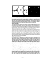
Fig. 20: The complete Starfinder menu structure.
page 27
Select Item:
Glossary
A...
Accretion Disk
Etc.
B...
C...
D...
E...
F...
G...
H...
I...
J...
K...
L...
M...
N...
O...
P...
Q...
R...
S...
T...
U...
V...
W...
X...
Y...
Z...
Select Item:
Utilities
Timer
Set
Start & Stop
Alarm
Set
On & Off
Eyepiece Calc.
Field of View
Magnification
Suggest
Display Options
Sun Warning
Getting Started
Brightness Adj.
Contrast Adj.
Battery Alarm
Landmark Survey
Sleep Scope
Park Scope
Select Item:
Setup
Align
One Star
Two Star
Date
Time
Daylight Saving
Telescope
Focal Length
Az/Alt Ratio
Train Drive
Tracking Rate
Reverse L/R
Reverse Up/Dn
Calibrate Motor
High Precision
Targets
Astronomical
Terrestrial
Site
Select
Add
Delete
Edit
Owner Info
Download
Statistics
Reset
Starfinder Menus
Object Menu
Almost all observing with Starfinder is performed using the Object menu. (Note:
Exceptions include Guided Tour and Landmark Survey.) See “GO TO SATURN,” page
20, for an example of observing using the Object menu. Also see “USING THE
GUIDED TOUR,” page 21.
Many Starfinder menu categories contain databases. A Starfinder database is a list of
viewable objects. When one of these objects is selected, Starfinder moves your telescope (if properly aligned) and points it at the selected object.
Object Menu Options:
Solar System is a database of the eight planets (Earth is not included) in order out
from the Sun, followed by the Moon, asteroids, and comets.
Constellation is a database of all 88 Northern and Southern Hemisphere constellations. When this menu option is chosen and a constellation name appears on the first
line of the screen, press GO TO once to change the second line to the name of the
brightest star in the constellation. Press GO TO a second time to slew the telescope
to that star. Use the Scroll keys to cycle through the list of stars in the constellation,
from brightest to dimmest.
Deep Sky is a database of objects outside our Solar System such as nebulae, star
clusters, galaxies, and quasars.
Star is a database of stars listed in different categories such as named, double, variable, or nearby.
User Objects allows the user to define deep-sky objects of specific interest that are
not currently in the Starfinder database. See "APPENDIX C," page 42, for detailed
information.
Landmarks stores the location of terrestrial points of interest in the permanent
Starfinder database.
IMPORTANT NOTE: To use the Landmark function, the telescope must be
located and aligned exactly as when the landmark was added to the
database.
•
Select: To select a landmark already in the database, choose the Select option
and scroll through the list. Press ENTER to select a landmark, then press GO TO
and the telescope slews to the object.
•
Add: To add a landmark, choose the Add option. Enter the name of the landmark.
Locate the object with the Arrow keys (the telescope must be aligned) and center
the landmark. Press ENTER.
Use the Landmark Survey option in the Utilities menu to sequentially view all landmarks entered into Starfinder. See "LANDMARK SURVEY," page 32.
Identify is an exciting feature for an observer who wants to scan the night sky and
start exploring.
After the telescope has been properly aligned, use the Starfinder Arrow keys to move
about in the sky, and then follow this procedure:
IMPORTANT NOTE: Only use the Arrow keys to move the telescope during
the Identify procedure. Do not loosen the telescope locks, or move the base,
or alignment will be lost.
page 28
1. When a desired object is visible in the eyepiece, press MODE until the "Select
Item: Object" menu is displayed.
2. Scroll through the Object menu options until "Object: Identify" displays.
3. Press ENTER to search the database for the identity of the object being observed.
4. If the telescope is not directly on a Starfinder database object, the nearest
database object is located and displayed on the screen. Press GO TO and the
telescope slews to that object.
Event Menu
The Event menu provides access to dates and times of astronomical events. The
Event database includes:
Sunrise and Sunset calculates the time that the Sun rises or sets on the current date.
Find rise and set times for other dates (e.g., a date three months in the past or future)
by entering the new date into the "Setup: Date" menu.
Moonrise and Moonset calculates the time that the Moon rises or sets on the current
date. Find rise and set times for other dates by entering a new date into the "Setup:
Date" menu.
Moon Phases displays the date and time of the next Full, New, 1st Quarter, and 3rd
Quarter Moon.
Meteor Showers provides information on upcoming meteor showers (e.g., the
Perseids, the Leonids, etc.), the dates of the showers, and when they reach maximum.
NOTE: Meteors are fast moving objects that cover large areas of the sky
and are usually best observed with the naked eye.
NEVER point the
telescope directly
at or near the
Sun at any time!
Observing the
Sun or an eclipse
of the Sun, even
for the smallest
fraction of a second, will result in
instant and irreversible eye damage, as well as
physical damage
to the telescope
itself.
Solar Eclipse lists upcoming Solar Eclipses, including the date and type (total, annular, or partial) of eclipse, and the location and time of the first and last contacts of the
Moon's shadow. Use the Scroll Up and Down keys to display the available data.
Lunar Eclipse lists upcoming Lunar Eclipses, including the date and type (total, partial,
penumbral) of eclipse. Use the Scroll Up and Down keys to display the available data.
Min. (Minimum) of Algol is the minimum brightness of the dramatic eclipsing binary
star system, Algol. It is relatively close at a distance of 100 light years. Every 2.8 days
during a 10-hour period, Algol undergoes a major change in apparent magnitude as
one of the two stars passes behind the other. The combined magnitude of the two
stars thus dips from +2.1 to a minimum of +3.4 halfway through the eclipse as the second star is hidden. Starfinder calculates minimum magnitude time at mid-eclipse.
Autumn and Vernal Equinox calculates the time and date of the fall or spring equinox
of the current year.
Winter and Summer Solstice calculates the time and date of the winter or summer
solstice of the current year.
Glossary Menu
The Glossary menu provides an alphabetical listing of definitions and descriptions for
common astronomical terms and Starfinder functions. Access directly through the
Glossary menu or through hypertext words embedded in Starfinder.
A hypertext word is any word in [brackets], usually found when in the Starfinder Help
function or in a scrolling message such as a description of a planet or star. Press
ENTER whenever a hypertext word is displayed and Starfinder links directly to the
glossary entry for that word.
page 29
To access a hypertext word directly from the Glossary menu, use the Scroll keys to
scroll through the alphabet. Press ENTER on the desired letter. Scroll to the desired
entry, then press ENTER to read the description.
Utilities Menu
The Utilities menu provides access to several extra features within Starfinder, including a countdown timer and an alarm. The Utilities functions include:
Timer selects a countdown timer. This feature is useful for functions such as astrophotography. To use the Timer, press ENTER, then choose "Set" or "Start/Stop."
•
Set: Enter the time to be counted down (in hours, minutes, and seconds), then
press ENTER.
•
Start/Stop: Activates the timer set previously. Use the Scroll keys to toggle
between ON and OFF. When ON is displayed, press ENTER to activate the timer.
When the timer runs out, four beeps sound and the timer is deactivated.
Alarm selects a time for an alarm signal as a reminder. To use the Alarm, press
ENTER, then choose "Set" or "Start/Stop."
•
Set: Enter the time of day for the alarm to sound (in hours, minutes, and seconds),
then press ENTER.
•
Start/Stop: Activates the alarm set previously. Use the Scroll keys to toggle
between ON and OFF. When ON is displayed, press ENTER to activate the alarm.
When the alarm time arrives, Starfinder beeps. Press ENTER to deactivate the
alarm.
Eyepiece Calc calculates information about an eyepiece for the specific telescope to
which Starfinder is connected:
•
Field of View: Scroll through a list of available eyepieces. When an eyepiece is
selected, the field of view is calculated.
•
Magnification: Scroll through a list of available eyepieces. When an eyepiece is
selected, the magnification is calculated.
•
Suggest: Starfinder calculates and suggests the best eyepiece for viewing, based
on the telescope and the object being viewed.
Display Options enables or disables Starfinder’s two initial displays. If both displays
are disabled, Starfinder begins with the Date display.
•
Sun Warning: Turns the Sun warning message on or off.
•
Getting Started: Turns the “Getting Started” message on or off.
Brightness Adj: Adjusts the brightness of the display using the Scroll keys. When
complete, press ENTER.
Contrast Adj: Adjusts the contrast of the display using the Scroll keys. When complete, press ENTER.
NOTE: This feature is usually only required in very cold weather.
Landmark Survey automatically slews the telescope to all user-defined landmarks
with a short pause at each location. Press ENTER to start the survey. While a slew is
in progress, press any key to skip that object and go to the next landmark on the list.
To observe a landmark for a longer period, press MODE when paused on the object
to stop the survey. Press ENTER to restart the survey at the first object on the list.
Sleep Scope is a power saving option that shuts down Starfinder and the telescope
without forgetting its alignment. Press ENTER to activate the Sleep function.
Starfinder goes dark, but the internal clock keeps running. Press any key, except
ENTER, to re-activate Starfinder and the telescope.
page 30
Park Scope is designed for a telescope that is not moved between observing sessions. Align the telescope one time, then use this function to park the telescope. Next
time it is powered up, enter the correct date and time – and no alignment is required.
Pressing ENTER causes the telescope to move to its pre-determined Park position.
Once parked, the screen prompts you to turn off the power (i.e., unplugging the battery pack).
IMPORTANT NOTE: When the Park Scope option is chosen and the
display prompts to turn off the telescope power, Starfinder is unable to be
returned to operation without unplugging the battery pack and then
plugging it back in.
Setup Menu
The Setup menu’s primary function is to align the telescope (see "ALIGN YOUR TELESCOPE USING STARFINDER," page 20). However, there are numerous other features available within Setup. These options include:
Date changes the date used by Starfinder. This function is useful to check events in
the past or future. Example: set the Date for a day three months in the future and then
check the" Select Item: Event" menu for the Sunset time or Moon phase on that date.
See “EVENT MENU,” page 29.
Time changes the time entered into Starfinder. Setting the correct time is critical for
Starfinder to properly calculate locations and events.
Daylight Saving is used to set the status of Daylight Savings time.
NOTE: Daylight Savings Time may be referred to by a different name in
various areas of the world. Check local time to verify.
Telescope accesses the following options:
•
Focal Length: Displays the focal length of the selected telescope.
•
Az Ratio and Alt Ratio: The Az (Azimuth or horizontal) ratio and Alt (Altitude or
vertical) ratio refers to the gears installed in the telescope motors. Do not alter
these numbers.
•
Train Drive: Trains the motors to locate objects with more precision.
NOTE: If you are experiencing any problems with pointing accuracy, follow
the procedure described in “TRAINING THE DRIVE,” page 19, to insure
accurate pointing and tracking.
Tracking Rate: Changes the speed at which the telescope tracks targets in the sky.
a. Sidereal: The default setting for Starfinder; sidereal rate is the standard rate
at which stars move from East to West across the sky due to the rotation of
the Earth.
b. Lunar: Choose this option to properly track the Moon over long observing
sessions.
c.
Custom: Allows entry of user-defined tracking rates.
•
Reverse L/R: Reverses the functions of the Left and Right Arrow keys (i.e., the
Right key moves the telescope to the left).
•
Reverse UP/DOWN: Reverses the functions of the Up and Down Arrow keys (i.e.,
the Up key moves the telescope down).
page 31
•
Calibrate Motor: If the telescope motors appear to have a problem, use this
option to retest the motors before doing a Reset. This option is also used if a
Starfinder unit is moved between telescopes to match Starfinder to the telescope.
•
High Precision: If High Precision is turned on when looking for a faint celestial
object (i.e., a nebula or galaxy), Starfinder first slews to a nearby bright star and
requests "ENTER to Sync." Center the star in the eyepiece, then press ENTER.
At that point the telescope has a high precision alignment to that part of the sky
and it then slews to the object that was originally requested.
Targets switches between astronomical targets and terrestrial targets. If
"Astronomical" is selected, the telescope tracking motor is activated. If "Terrestrial" is
selected, the tracking motor is turned off. See "OBSERVE A STAR USING THE
AUTOMATIC TRACKING FEATURE," page 16, for more information.
Site provides access to the following options:
•
Select: Displays the currently selected observing site and also allows you to
select other sites you have entered into a user-defined database (see "Add"
below). Use the Scroll keys to cycle through all available sites in this database.
Press ENTER when the site you wish to select displays. Use this option when you
move to a different geographic location.
NOTE: Only the site that is entered during Initialization (see page 17) will be
displayed in this database until other sites are entered with the "Add" option.
•
Time Zone
Atlantic
Eastern
Central
Mountain
Pacific
Hawaii
Shift
-4 Hours
-5 Hours
-6 Hours
-7 Hours
-8 Hours
-10 Hours
•
•
Table 1: Time Zone Shift.
Add: Allows you to add new observing sites to the database (up to six sites may
be stored). Scroll through the list of Countries/States. Press ENTER when the site
you wish to add displays. Then choose the desired city in the same manner.
Delete: Deletes a stored site from the database.
Edit: Edits a selected site, including: the name, latitude, longitude, and time zone.
Time zone refers to the Greenwich Mean Time (GMT) time zone shift. Users West
of Greenwich, England, use “-” hours, East of Greenwich use “+” hours. For the
United States, look up the time zone shift in Table 1.
NOTE: Starfinder compensates for daylight savings time, if selected (see
"DAYLIGHT SAVING," page 31).
Owner Info accesses the owner information menu options, including:
•
Name: A user may enter both his or her first and last names using the Up and
Down Arrow keys to cycle through the alphabet. Use the Right and Left Arrow keys
to move across the text. Press ENTER when the entry is complete.
•
Address: Use the Up and Down Arrow keys to enter your street address, city,
state, and zip code. Press ENTER when the entry is complete.
Download transfers information from a personal computer or another Starfinder.
NOTE: The Download function requires the optional Cable Set. See the
instruction sheet for the optional cable set for more information on how to
download.
Statistics provides basic statistical data about Starfinder, including:
•
Characters Free: Shows how much room is available in user-defined object
memory.
•
Version: Shows the current version of the Starfinder software.
Reset completely resets Starfinder. Starfinder requires initialization again after a
Reset before proceeding with observations. See “ INITIALIZING STARFINDER,” page
17. You will also need to perform “TRAINING THE DRIVE,” page 19, after a Reset.
page 32
PART 3: Caring for Your Telescope
Cleaning
The lens or mirror surfaces should be cleaned as infrequently as possible. Front surface aluminized mirrors, in particular, should be cleaned only when absolutely necessary. In all cases, avoid touching any mirror surface. A little dust on the surface of a
mirror or lens causes negligible loss of performance and should not be considered reason to clean the surface. When lens or mirror cleaning does become necessary, use
a camel’s hair brush or compressed air gently to remove dust. If the telescope’s dust
cover is replaced after each observing session, cleaning of the optics will rarely be
required.
Mount and Tripod Adjustments
Every Meade 4504 Telescope equatorial mount and tripod is factory inspected for
proper fit and function prior to shipment. It is unlikely that you will need to adjust or
tighten these parts after receipt of the telescope. However, if the instrument received
unusually rough handling in shipment, it is possible that some of these assemblies can
be loose. To make adjustments you will need a 1/2" or 11/16" socket or adjustable end
wrench, a 5/64" hex wrench, and a Phillips-head screwdriver.
The equatorial mount has four main areas that
can be adjusted: A loose polar shaft can be tight3
ened by releasing a 5/64" hex set-screw that is
on the side of the 11/16" polar shaft acorn cap
4
nut (3, Fig. 21), and then turning the 11/16"
acorn cap nut clockwise to a firm feel, and then
tightening the 5/64" hex set-screw. A loose
2
2
Azimuth base (4, Fig. 21), can be tightened by
turning the 11/16" Azimuth shaft bolt, located
1
underneath the mount and in between the three
tripod legs, clockwise to a firm feel. The R.A. (1,
Fig. 11), and Dec (12, Fig. 11) worm block
assemblies can have backlash removed by Fig. 21: Maintenance adjustments.
releasing the two Phillips-head screws on each
assembly, applying pressure to the worm block against the worm gear, and then tightening the Phillips-head screws. Note that overtightening of any of the nuts, bolts, or
screws can inhibit the smooth rotating action of the axes and gears, and may result in
stripping the threads.
The tripod legs have 1/2" nuts (1, Fig. 21), and Phillips-head screws (2, Fig. 21) that
may have backed off. Tighten to a firm feel for the most sturdy performance of the telescope.
Diagonal
Assembly
Diagonal Mirror
Focused Image
Fig. 22: The Newtonian reflecting telescope.
page 33
Primary Mirror
Primary Mirror-Tilt
Screws
3
2
1
2
3
Fig. 24: Primary mirror cell.
Fig. 23: Diagonal assembly.
Collimation (Alignment) of the Optics
Your telescope is optically aligned at the factory prior to shipment. It is unlikely that you
will need to align, or collimate, the optics after receipt of the instrument. However, if
the telescope received unusually rough handling in shipment, it is possible that the
optics must be re-aligned for best optical performance. Take the time to familiarize
yourself with the following collimation procedure, so that you will recognize a properly
collimated instrument and can adjust the collimation yourself, if necessary.
Correct collimation
The properly collimated (aligned) mirror system in the Meade 4504 Telescope assures
the sharpest images possible. This occurs when the primary mirror and diagonal mirror are tilted so that the focused image (Fig. 22) falls directly through the center of the
focuser drawtube. These mirror tilt adjustments are made with the diagonal assembly
(Fig. 22) and the primary mirror cell (Fig. 22), and will be discussed later.
To inspect the view of the mirror collimation, look down the focuser drawtube with the
eyepiece removed. The edge of the focuser drawtube will frame the reflections of the
primary mirror with the 3 mirror clips (2, Fig. 25), the diagonal mirror (3, Fig. 25), the
spider vanes (4, Fig. 25), and your eye (5, Fig. 25). Properly aligned, all of these
reflections will appear concentric (i.e. centered) as illustrated in Fig. 25. Any deviation
from the concentric reflections will require adjustments to the diagonal assembly (Fig.
23), and/or the primary mirror cell (Fig. 24).
Spider vane adjustments
If the diagonal mirror (1, Fig. 26) is left or right of center within the drawtube (2, Fig.
26), loosen the spider vane adjustment/lock knobs (1, Fig. 23) located on the outside
surface of the main tube and slide the entire diagonal assembly up or down the tube
along the slotted holes, until the diagonal mirror is centered in the drawtube. If the
diagonal mirror (1, Fig. 26) is above or below of center within the drawtube, thread in
one of the spider vane adjustment/ lock knobs while unthreading the other. Only make
adjustments to two knobs at a time until the diagonal mirror is in the drawtube. When
the spider vane is correctly positioned, it will look like Fig. 27 (the diagonal mirror is
misaligned).
Diagonal holder adjustments
If the diagonal mirror (1, Fig. 27) is centered in the drawtube (2, Fig. 27), but the primary mirror is only partially visible in the reflection (3, Fig. 27), the three Phillips-head
diagonal tilt screws (2, Fig. 23) must be unthreaded slightly to the point of where you
can rotate the diagonal holder (3, Fig. 23) from side-to-side by grasping the diagonal
holder with your hand and rotating until you see the primary mirror become as centered in the reflection of the diagonal mirror as possible. Once you are at the best position, thread in the three Phillips-head diagonal tilt screws to lock the rotational position. Then, if necessary, make adjustments to these three Phillips-head screws to
page 34
refine the tilt-angle of the diagonal mirror until the entire primary mirror can be seen
centered within the diagonal mirror reflection. When the diagonal mirror is correctly
aligned, it will look like Fig. 28 (the primary mirror is shown out of alignment).
Primary mirror adjustments
If the diagonal mirror (1, Fig. 28) and the reflection of the primary mirror (2, Fig. 28)
appear centered within the drawtube (3, Fig. 28), but the reflection of your eye and the
reflection of the diagonal mirror (4, Fig. 28) appear off-center, you will need to adjust
the primary mirror tilt Phillips-head screws of the primary mirror cell (3, Fig. 24). These
primary tilt screws are located behind the primary mirror, at the lower end of the main
tube (Fig. 22). To adjust the primary mirror tilt screws, first unscrew several turns the
three hex-head primary mirror cell locking screws (2, Fig. 24) that are next to each primary mirror tilt Phillips-head screw. Then by trial-and-error, turn the primary mirror tilt
Phillips-head screws (3, Fig. 24) until you develop a feel for which way to turn each
screw to center the reflection of your eye. Once centered, as in Fig. 25, turn the three
hex-head primary mirror cell locking screws (2, Fig. 24) to relock the tilt-angle adjustment.
1
2
2
2
3
4
1
5
Fig. 25: Correct collimation.
Fig. 26: Spider vane misalignment.
1
1
3
2
4
3
2
Fig. 27: Diagonal mirror misalignment.
page 35
Fig. 28: Primary mirror misalignment.
Star testing the collimation
With the collimation performed, you will want to test the accuracy of the alignment on
a star. Use the H 25mm eyepiece and point the telescope at a moderately bright (second or third magnitude) star, then center the star image in the telescope’s field-of-view.
With the star centered, follow the method below:
•
Bring the star image slowly out of focus until one or more rings are visible around
the central disc. If the collimation was performed correctly, the central star disk and
rings will be concentric circles, with a dark spot dead center within the out-of-focus
star disk (this is the shadow of the secondary mirror), as shown in C, Fig. 29. (An
improperly aligned telescope will reveal elongated circles (A, Fig. 29), with an offcenter dark shadow.)
•
If the out-of-focus star disk appears elongated (B, Fig. 29), you will need to adjust
the primary mirror Phillips-head tilt screws of the primary mirror cell (3, Fig. 24).
•
To adjust the primary mirror tilt screws (3, Fig. 24), first unscrew several turns the
three hex-head primary mirror cell locking screws (2, Fig. 24), to allow free turning
movement of the tilt knobs.
•
As you make adjustments to the primary mirror tilt screws (3, Fig. 24), you will
notice that the out-of-focus star disk image will move across the eyepiece field.
Choose one of the three primary mirror tilt screws that will move the star disk
image to the center of the eyepiece field.
•
Repeat this process as many times as necessary until the out-of-focus star disk
appears as in C, Fig. 29, when the star disk image is in the center of the eyepiece
field.
•
With the star testing of the collimation complete, tighten the three hex-head
primary mirror locking screws (2, Fig. 24).
A
B
Fig. 29: Collimation.
page 36
C
MODEL 4504 TELESCOPE SPECIFICATIONS
Optical design ................................................................Newtonian Reflector
Clear aperture ..............................................................114mm (4.5”)
Focal length ....................................................................910mm
Focal ratio (photographic speed) ..................................f/8
Resolving power ............................................................1.0 arc secs
Multi-coatings on objective lens ....................................Standard
Limiting visual stellar magnitude (approx.) ....................12.4
Image scale ..................................................................1.6°/inch
Maximum practical visual power ..................................325X
Optical tube dimensions
(dia. x length) ..........................................................14cm x 86.4cm (5.5” x 34”)
Eyepieces
Modified Achromatic ..............................................H 25mm (0.965” O.D.)
Modified Achromatic ..............................................H 12.5mm (0.965” O.D.)
Modified Achromatic ..............................................SR 4mm (0.965” O.D.)
Barlow ....................................................................3x magnification
Telescope mounting........................................................German equatorial mount
Setting circle diameters ..........................................6.2cm (2.45")
Input voltage ..........................................................12-volts DC
Motor Drive System ................................................DC servo motors with encoders, both axes
Slow-Motion Controls ....................................................Electric, 7 speeds, both axes
Hemispheres of operation ..............................................North and South, switchable
Materials
Tube body ..............................................................Aluminum
Mounting ................................................................Die-cast aluminum
Telescope net weight:
(telescope only, without batteries, eyepieces)................10.5 kg (23 lbs.)
Telescope shipping weight
(telescope, accessories, instruction manual, packing) ..14 kg (31 lbs.)
Battery Life (approx.)
with Starfinder ........................................................20 hrs.
STARFINDER SPECIFICATIONS
Processor ......................................................................68HC11, 8MHz
Flash Memory ................................................................512KB, reloadable
Keypad ..........................................................................10 key
Display ............................................................................2 line, 16 character LCD
Backlight ........................................................................Red LED
Coil Cord ........................................................................24"
STARFINDER DIMENSIONS
Length ............................................................................14.2cm
Width (LCD end) ............................................................78.0cm
Width (Connector end) ..................................................53.5cm
Depth ..............................................................................23.5cm
page 37
(5.60")
(3.08")
(2.10")
(0.93")
APPENDIX A: Calculating Eyepiece Power
The power, or magnification of the telescope depends on two optical characteristics:
the focal length of the main telescope and the focal length of the eyepiece used during a particular observation. The focal length of the 4504 telescope is fixed at 910mm.
To calculate the power in use with a particular eyepiece, divide the focal length of the
eyepiece into the focal length of the main telescope. E.g., using the H 25mm eyepiece
supplied with the telescope, the power is calculated as follows:
Power =
telescope focal length = 910mm
= 36x
eyepiece focal length
25mm
The maximum practical magnification is determined by the nature of the object being
observed and, most importantly, by the prevailing atmospheric conditions. Generally
powers of perhaps 35x to 175x will be useful most often, consistent with high image
resolution. When unsteady air conditions prevail (as witnessed by rapid “twinkling” of
the stars), extreme high-power results in “empty magnification,” where the object detail
observed is actually diminished by the excessive power.
The 3x Barlow lens included with your telescope triples the eyepiece magnification. To
calculate the power of an eyepiece used with a Barlow lens, multiply the eyepiece
power by the Barlow value. E.g., using the H 25mm eyepiece, the power or magnification of the 4504 telescope (as calculated in the example above) is 36x and the
Barlow value is 3x. The total power using the Barlow lens is:
Total power = eyepiece power x Barlow value = 36 x 3 = 108x
To install the Barlow lens, first place the Barlow lens into the focuser assembly
(remove the focuser dustcap, if necessary), followed by the eyepiece (Fig. 30).
Tighten the Barlow thumbscrews and the focuser thumbscrews to a firm feel only.
Eyepiece
Thumbscrew
Barlow
Focuser
Assembly
Thumbscrew
Focus knob
Fig. 30: Insert Barlow into focuser
assembly.
page 38
APPENDIX B: Terrestrial Viewing, Celestial Movement,
and Polar Alignment
Terrestrial Viewing
The 4504 is an excellent, high-resolution terrestrial (land) telescope. Viewing terrestrial
objects requires looking along the Earth's surface through heat waves. These heat
waves often cause degradation of image quality. Low power eyepieces, like the H 25mm
eyepiece, magnify these heat waves less than higher power eyepieces. Therefore, low
power eyepieces provide a steadier, higher quality image. If the image is fuzzy or illdefined, reduce to a low-power, where the heat waves do not have such an effect on
image quality. Observing in early morning hours, before the ground has built up internal
heat, produces better viewing conditions than during late-afternoon hours.
Astronomical Observing
Used as an astronomical instrument, your telescope has many optical and electromechanical capabilities. It is in astronomical applications where the high level of optical performance is readily visible. The range of observable astronomical objects is,
with minor qualification, limited only by the observer’s motivation.
Polar Alignment
Lunar or planetary photography requires that the telescope be Polar aligned. In Polar
Alignment, the telescope is oriented so that the horizontal and vertical axes of the telescope are lined up with the celestial coordinate system.
In order to understand Polar Alignment, it is essential to have an understanding of how
and where to locate celestial objects as they move across the sky. This section provides a basic introduction to the terminology of Polar-aligned astronomy, and includes
instructions for finding the celestial pole and for finding objects in the night sky using
Declination and Right Ascension.
Understanding Celestial Movements and Coordinates
Understanding where to locate celestial objects and how those objects move across
the sky is fundamental to enjoying the hobby of astronomy. Most amateur astronomers
adopt the simple practice of “star-hopping” to locate celestial objects by using star
charts or astronomical software which identify bright stars and star patterns (constellations) that serve as “road maps” and “landmarks” in the sky. These visual reference
points guide amateur astronomers in their search for astronomical objects.
Understanding How Astronomical Objects Move
Due to the Earth’s rotation, celestial bodies appear to move from East to West in a
curved path through the sky. The path they follow is known as their line of Right
Ascension (R.A.). The angle of the path that they follow is known as their line of
Declination (Dec). The system of R.A. and Dec is analogous to the Earth-based coordinate system of latitude and longitude. Like Earth, imaginary lines have been drawn
on the celestial sphere to form a coordinate grid. Celestial object positions on the
Earth's surface are specified by their latitude and longitude.
Understanding Celestial Coordinates
Celestial objects are mapped according to the R.A. and Dec coordinate system on the
“celestial sphere” (Fig. 31), the imaginary sphere on which all stars appear to be
placed. The Poles of the celestial coordinate system are defined as those two points
where the Earth's rotational axis, if extended to infinity, North and South, intersect the
celestial sphere. Thus, the North Celestial Pole is that point in the sky where an extension of the Earth's axis through the North Pole intersects the celestial sphere. In fact,
this point in the sky is located near the North Star, or Polaris.
page 39
ation
clin
De
On the surface of the Earth,
North
“lines of longitude” are drawn
Celestial
+90 Dec.
between the North and South
Pole
Star
(Vicinity
Poles. Similarly, “lines of latitude”
of Polaris)
are drawn in an East-West direc1
tion, parallel to the Earth's equa11
13 12
tor. The celestial equator is sim10
15 14
9
16
8
17
7
ply a projection of the Earth's
Earth’s
18
6
5
Rotation
19
equator onto the celestial
4
20 21
3
Celestial
2
22 23
1
0
sphere. Just as on the surface of
Equator
Right Ascension
the The celestial equivalent to
0 Dec.
Earth
latitude
is
called
2
South
“Declination,” or simply “Dec.” It
Celestial
is measured in degrees, minutes
-90 Dec.
Pole
or seconds north ("+") or south
("-") of the celestial equator. Thus
any point on the celestial equator Fig. 31: Celestial sphere.
(which passes, for example,
through the constellations Orion, Virgo and Aquarius) is specified as having 0°0'0"
Dec. The Dec of the star Polaris, located very near the North Celestial Pole, is +89.2°.
The celestial equivalent to Earth longitude is called “Right Ascension,” or “R.A.” It is
measured in hours, minutes, and seconds from an arbitrarily defined “zero” line of R.A.
passing through the constellation Pegasus. R.A. coordinates range from 0hr0min0sec
up to (but not including) 24hr0min0sec. Thus there are 24 primary lines of R.A., located at 15 degree intervals along the celestial equator. Objects located further and further east of the prime (0h0m0s) R. A. grid line carry increasing R.A. coordinates.
With all celestial objects therefore capable of being specified in position by their celestial coordinates of R.A. and Dec, the task of finding objects (in particular, faint objects)
in the telescope is vastly simplified. The setting circles, R.A. (15, Fig. 2a) and Dec (9,
Fig. 2a)of the Meade 4504 Telescope may be dialed, in effect, to read the object coordinates, and the object can be found without resorting to visual location techniques.
However, these setting circles may be used to advantage only if the telescope is first
properly aligned with the Celestial Pole.
Lining Up with the Celestial Pole
Objects in the sky appear to revolve around the Celestial Pole (actually, celestial objects
are essentially “fixed,” and their apparent motion is caused by the Earth’s axial rotation).
During any 24 hour period, stars make one complete revolution about the pole, making
concentric circles with the pole at the center. By lining up the telescope’s polar axis with
the North Celestial Pole (or, for observers located in Earth’s Southern Hemisphere, with
the South Celestial Pole), astronomical objects may be followed, or tracked, by moving
the telescope about one axis, the polar axis.
Virtually all of the required telescope tracking will be in R.A. (if
the telescope were perfectly
aligned with the pole, no Dec
tracking of stellar objects would
be required). For the purposes of
casual visual telescopic observations, lining up the telescope’s
polar axis to within a degree or
two of the pole is more than sufficient.
page 40
Little Dipper
Big Dipper
Fig. 32: Locating Polaris.
Polaris
Cassiopeia
Using Setting Circles
The setting circles of the Polar aligned equatorial mount can be used to locate faint
celestial objects not easily found by direct visual observation. To use the setting circles, follow this procedure:
•
Use a star chart or star atlas, and look up the celestial coordinates, Right
Ascension and Declination (R.A. and Dec), of an easy-to-find bright star that is
within the general vicinity of the faint object you wish to locate.
•
Center the determined bright star in the telescope’s field of view.
•
Manually turn the R.A. setting circle (15, Fig. 2a) to read the R.A. of the object now
in the telescope’s eyepiece.
•
The setting circles are now calibrated (the Dec setting circle (9, Fig. 2a) is factory
calibrated). To locate a nearby faint object using the setting circles, determine the
faint object’s celestial coordinates from a star chart and move the telescope in
R.A. and Dec until the setting circles read the R.A. and Dec of the object you are
attempting to locate. If the above procedure has been carefully performed, the
faint object will now be in the field of a low power eyepiece.
•
The R.A. setting circle must be manually re-calibrated on the current R. A. of a star
every time the telescope is set up, and reset to the centered object’s R.A.
coordinate before moving to a new R.A. coordinate setting. The R.A. setting circle
has two sets of numbers. The inner set is for Southern hemisphere use while the
outer set (the set closest to the R.A. gear) is for use by observers located North
of the Earth’s equator (e.g., in North America and Europe).
Two-Star Polar Alignment
Besides One-Star Polar Alignment which was covered earlier in this manual (see
"ALIGNING YOUR TELESCOPE USING STARFINDER," page 20), another type of
alignment, Two-Star Polar Alignment, is also available.
Two-Star Polar Alignment requires some knowledge of the night sky. Starfinder provides a database of bright stars and two stars from this database are chosen by the
observer for alignment. The rest of the alignment procedure is identical to One-Star
Polar Alignment.
1. Perform steps 1 through 4 as described in the "ALIGN YOUR TELESCOPE
USING STARFINDER," page 20.
2 . Starfinder displays a database of stars for the observer to choose from. Use the
Scroll keys to scroll to a star that you wish to align upon. Select a star that you can
easily locate in the night sky.
3. Press ENTER. The telescope slews to the star for alignment. Use the Arrow keys
to move the telescope until the star is visible and centered in the eyepiece.
4. Press ENTER. Repeat the procedure for the second alignment star. The telescope
is aligned and you are now ready to use Starfinder's GO TO capabilities for a night
of observing.
page 41
APPENDIX C: Using Starfinder to Enter Celestial
Coordinates
Although Starfinder's database contains more than 1400 objects (stars, nebulae,
planets, etc.) that you can observe, you may eventually want to view objects that are
not part of the database. Starfinder provides a feature that allows you to enter an
object's R.A and Dec coordinates in the "User: Objects" option of Starfinder's Object
menu, and then will automatically slew the telescope to the user-entered coordinates.
In order to use this menu option, you first need to look up the R.A and Dec coordinates of the object or objects you wish to observe. Check out your local library, computer store, or bookstore for astronomy books, CD Roms, or magazines (such as Sky
& Telescope or Astronomy), to find coordinates of celestial objects. A list of the coordinates of 14 common stars are printed at the end of this manual; see "STAR LOCATOR," page 46.
The objects/coordinates you enter become part of your own permanent database,
called "User Objects." You may use this menu to view these object as often as you
like, but the objects' coordinates just need to be entered once.
To enter coordinates of an object into the "User: Objects" option of the Object
menu:
1. Make sure Starfinder has been initialized (see "INITIALIZING STARFINDER,"
page 17) and the telescope has been aligned (see "ALIGN YOUR TELESCOPE
USING STARFINDER," page 20).
2. After the telescope is aligned, "Select Item: Object" displays. (If necessary, use
the Scroll keys to scroll through the menus, as previously described, to find this
option.) Press ENTER.
3. "Object: Solar System" displays. Keep pressing the Scroll Up key until "Object:
User Object" displays and press ENTER.
4. "User Object: Select" displays. Press the Scroll Down key once. "User Object:
Add" displays. Press ENTER.
5. "Name" displays on the top line and a blinking cursor on the second line. Use the
Arrow keys (as previously described) to enter the name of the object you wish to
add to the database. When you are finished, press ENTER.
6. "Right Asc.: +00.00.0" displays. Use the Arrow keys to enter the digits for the
Right Ascension (R.A.) coordinate of your object. If necessary, use the Scroll Keys
to change "+" to "-." When you are finished, press ENTER.
7. "Declination: +00°.00'" displays. Use the Arrow keys to enter the digits for the
Declination (Dec) coordinate of your object. If necessary, use the Scroll Keys to
change "+" to "-." When you are finished, press ENTER.
8. Starfinder then prompts you to enter the Size of the object. This step is optional.
Use the Arrow keys to enter this information, if so desired, and press ENTER to
go to the next display. If you do not wish to enter this information, simply press
ENTER.
9. Starfinder then prompts you to enter the Magnitude of the object. This step is also
optional. Use the Arrow keys to enter this information, if so desired, and press
ENTER to go to the next display. "User Object: Add" displays again.
To GO TO a user-entered object:
1. With "User Object: Add" displayed, press the Scroll Up key once. "User Object:
Select" displays. Press ENTER.
2. Use the Scroll keys (if necessary) to scroll to the desired object. Press ENTER.
3. The name of the object and the R.A. and Dec coordinates display.
4. Press GO TO and the telescope slews to the object.
page 42
APPENDIX D: Helpful Charts
Latitude Chart for Major Cities of the World
To aid in the Polar Alignment procedure (see "TO POLAR ALIGN THE TELESCOPE," page 15), latitudes
of major cities around the world are listed below. To determine the latitude of an observing site not listed
on the chart, locate the city closest to your site. Then follow the procedure below:
Northern Hemisphere observers (N): If the site is over 70 miles (110 km) North of the listed city, add one
degree for every 70 miles. If the site is over 70 miles South of the listed city, subtract one degree per 70
miles.
Southern Hemisphere observers (S): If the site is over 70 miles North of the listed city, subtract one
degree for every 70 miles. If the site is over 70 miles South of the listed city, add one degree per 70 miles.
UNITED STATES
City
State
Latitude
Albuquerque
Anchorage
Atlanta
Boston
Chicago
Cleveland
Dallas
Denver
Detroit
Honolulu
Jackson
Kansas City
Las Vegas
Little Rock
Los Angeles
Miami
Milwaukee
Nashville
New Orleans
New York
Oklahoma City
Philadelphia
Phoenix
Portland
Richmond
Salt Lake City
San Antonio
San Diego
San Francisco
Seattle
Washington
Wichita
New Mexico
Alaska
Georgia
Massachusetts
Illinois
Ohio
Texas
Colorado
Michigan
Hawaii
Mississippi
Missouri
Nevada
Arkansas
California
Florida
Wisconsin
Tennessee
Louisiana
New York
Oklahoma
Pennsylvania
Arizona
Oregon
Virginia
Utah
Texas
California
California
Washington
District of Columbia
Kansas
35°
61°
34°
42°
42°
41°
33°
40°
42°
21°
32°
39°
36°
35°
34°
26°
46°
36°
30°
41°
35°
40°
33°
46°
37°
41°
29°
33°
38°
47°
39°
38°
EUROPE
City
Country
Latitude
Amsterdam
Athens
Bern
Copenhagen
Dublin
Frankfurt
Glasgow
Helsinki
Lisbon
Netherlands
Greece
Switzerland
Denmark
Ireland
Germany
Scotland
Finland
Portugal
52°
38°
47°
56°
53°
50°
56°
60°
39°
N
N
N
N
N
N
N
N
N
N
N
N
N
N
N
N
N
N
N
N
N
N
N
N
N
N
N
N
N
N
N
N
N
N
N
N
N
N
N
N
N
EUROPE (cont'd)
City
Country
Latitude
London
Madrid
Oslo
Paris
Rome
Stockholm
Vienna
Warsaw
England
Spain
Norway
France
Italy
Sweden
Austria
Poland
51°
40°
60°
49°
42°
59°
48°
52°
N
N
N
N
N
N
N
N
SOUTH AMERICA
City
Country
Latitude
Asuncion
Brasilia
Buenos Aires
Montevideo
Santiago
Paraguay
Brazil
Argentina
Uruguay
Chile
25°
24°
35°
35°
34°
ASIA
City
Country
Latitude
Beijing
Seoul
Taipei
Tokyo
Victoria
China
South Korea
Taiwan
Japan
Hong Kong
40°
37°
25°
36°
23°
AFRICA
City
Country
Latitude
Cairo
Cape Town
Rabat
Tunis
Windhoek
Egypt
South Africa
Morocco
Tunisia
Namibia
30°
34°
34°
37°
23°
AUSTRALIA
City
State
Latitude
Adelaide
Brisbane
Canberra
Alice Springs
Hobart
Perth
Sydney
Melbourne
South Australia
Queensland
New South Wales
Northern Territory
Tasmania
Western Australia
New South Wales
Victoria
35°
27°
35°
24°
43°
32°
34°
38°
page 43
S
S
S
S
S
N
N
N
N
N
N
S
N
N
S
S
S
S
S
S
S
S
S
APPENDIX E: Basic Astronomy
In the early 17th century, an Italian Scientist named Galileo, using a crude telescope
considerably smaller than your 4504, turned it to look towards the sky instead of
distant trees and mountains. What he saw, and what he realized about what he saw,
forever changed the way mankind thought of the universe. Imagine what it must have
been like being the first human to see moons revolve around the planet Jupiter or to
see the changing phases of Venus! Because of his observations, Galileo correctly
realized Earth's movement and position around the Sun, and in doing so, gave birth
to modern astronomy. Yet Galileo's telescope was so crude, he could not clearly make
out the rings of Saturn.
Galileo's discoveries laid the foundation for understanding the motion and nature of
the planets, stars, and galaxies. Building on his foundation, Henrietta Leavitt
determined how to measure the distance to stars; Edwin Hubble proposed a glimpse
into the origin of the universe; Albert Einstein unraveled the relationship of time and
light. Almost daily, using sophisticated successors to Galileo's crude telescope, such
as the Hubble Space Telescope, more and more mysteries of the universe are being
solved and understood. We are living in a golden age of astronomy.
Unlike other sciences, astronomy welcomes contributions from amateurs. Much of the
knowledge we have on subjects such as comets, meteor showers, variable stars, the
Moon, and our solar system comes from observations made by amateur astronomers.
So as you look through your Meade telescope, keep in mind Galileo. To him, a
telescope was not a mere machine of glass and metal, but something far more – a
window through which the beating heart of the universe might be glimpsed, a fuse to
set fire to mind and imagination.
Starfinder Glossary
Be sure to make use of Starfinder’s Glossary feature. The Glossary menu provides
an alphabetical listing of definitions and descriptions of common astronomical terms.
Access these directly through the Glossary menu or through hypertext words
embedded in Starfinder. See “GLOSSARY MENU," page 29, for more information.
Objects in Space
Listed below are some of the many astronomical objects that can be seen with the 4504:
Fig. 33: The Moon.
Note the deep
shadows in the craters.
The Moon
The Moon is, on average, a distance of 239,000 miles (380,000km) from Earth and is
best observed during its crescent or half phase when Sunlight strikes the Moon’s
surface at an angle. It casts shadows and adds a sense of depth to the view (Fig. 33).
No shadows are seen during a full Moon, causing the overly bright Moon to appear
flat and rather uninteresting through the telescope. Purchase a neutral Moon filter for
use when observing the Moon. Not only does it protect your eyes from the bright glare
of the Moon, but it also helps enhance contrast, providing a more dramatic image.
Using the 4504, brilliant detail can be observed on the Moon, including hundreds of
lunar craters and maria, described below.
Craters are round meteor impact sites covering most of the Moon’s surface. With no
atmosphere on the Moon, no weather conditions exist, so the only erosive force is
meteor strikes. Under these conditions, lunar craters can last for millions of years.
Maria (plural for mare) are smooth, dark areas scattered across the lunar surface.
These dark areas are large ancient impact basins that were filled with lava from the
interior of the Moon by the depth and force of a meteor or comet impact.
Twelve Apollo astronauts left their bootprints on the Moon in the late 1960's and early
1970's. However, no telescope on Earth is able to see these footprints or any other
artifacts. In fact, the smallest lunar features that may be seen with the largest
telescope on Earth are about one-half mile across.
page 44
Planets
Planets change positions in the sky as they orbit around the Sun. To locate the planets
on a given day or month, consult a monthly astronomy magazine, such as Sky and
Telescope or Astronomy. Listed below are the best planets for viewing through the
4504.
Venus is about nine-tenths the diameter of Earth. As Venus orbits the Sun, observers
can see it go through phases (crescent, half, and full) much like those of the Moon.
The disk of Venus appears white as Sunlight is reflected off the thick cloud cover that
completely obscures any surface detail.
Fig. 34: Jupiter and
its four largest
moons. The moons
can be observed in
a different position
every night.
Fig. 35: Saturn has
the most extensive
ring structure in our
Solar System.
Mars is about half the diameter of Earth, and appears through the telescope as a tiny
reddish-orange disk. It may be possible to see a hint of white at one of the planet’s
Polar ice caps. Approximately every two years, when Mars is closest to Earth in its
orbit, additional detail and coloring on the planet's surface may be visible.
Jupiter is the largest planet in our solar system and is 11 times the diameter of Earth.
The planet appears as a disk with dark lines stretching across the surface. These lines
are cloud bands in the atmosphere. Four of Jupiter’s 16 moons (Io, Europa,
Ganymede, and Callisto) can be seen as “star-like” points of light when using even
the lowest magnification. These moons orbit Jupiter so that the number of moons
visible on any given night changes as they circle around the giant planet.
Saturn is nine times the diameter of Earth and appears as a small, round disk with
rings extending out from either side. In 1610, Galileo, the first person to observe
Saturn through a telescope, did not understand that what he was seeing were rings.
Instead, he believed that Saturn had “ears.” Saturn’s rings are composed of billions of
ice particles ranging in size from a speck of dust to the size of a house. The major
division in Saturn's rings, called the Cassini Division, is occasionally visible through
the 4504. Titan, the largest of Saturn’s 18 moons can also be seen as a bright, starlike object near the planet.
Deep-Sky Objects
Star charts can be used to locate constellations, individual stars and deep-sky
objects. Examples of various deep-sky objects are given below:
Fig. 36: The
Pleiades is one of
the most beautiful
open clusters.
Stars are large gaseous objects that are self-illuminated by nuclear fusion in their
core. Because of their vast distances from our solar system, all stars appear as
pinpoints of light, irrespective of the size of the telescope used.
Nebulae are vast interstellar clouds of gas and dust where stars are formed. Most
impressive of these is the Great Nebula in Orion (M42), a diffuse nebula that appears
as a faint wispy gray cloud. M42 is 1600 light years from Earth.
Open Clusters are loose groupings of young stars, all recently formed from the same
diffuse nebula. The Pleiades is an open cluster 410 light years away. Through the
4504, numerous stars are visible.
Constellations are large, imaginary patterns of stars believed by ancient civilizations
to be the celestial equivalent of objects, animals, people, or gods. These patterns are
too large to be seen through a telescope. To learn the constellations, start with an
easy grouping of stars, such as the Big Dipper in Ursa Major. Then, use a star chart
to explore across the sky.
Galaxies are large assemblies of stars, nebulae, and star clusters that are bound by
gravity. The most common shape is spiral (such as our own Milky Way), but galaxies
can also be elliptical, or even irregular blobs. The Andromeda Galaxy (M31) is the
closest spiral-type galaxy to our own. This galaxy appears fuzzy and cigar-shaped. It
is 2.2 million light years away in the constellation Andromeda, located between the
large “W” of Cassiopeia and the great square of Pegasus.
page 45
A Roadmap to the Stars
The night sky is filled with wonder and
intrigue. You too can enjoy exploring
the universe simply by following a few
pointers on a roadmap to the stars.
Rigel
Orion
Betelgeuse
Andromeda
Gemini
Pollux
First, find the Big Dipper which is part of
the constellation Ursa Major. The Big
Dipper is usually easy to locate year
round in North America.
Extending directly out from the far side
of the Big Dipper’s cup is the
constellation Orion. One of the most
exquisite areas of the winter sky, Orion
is distinguished by Orion’s belt, which is
marked by three stars in a row. The
Orion Nebula is located South of the
belt and is one of the most observed
deep-sky
objects
by
amateur
astronomers.
Castor
Pegasus
“Summer
Triangle”
Polaris
“Sickle”
Regulus
Deneb
Cygnus
Vega
Lyra
Altair
Leo
“Big Dipper”
Boötes
Arcturus
Aquila
Virgo
Spica
Antares
Scorpius
Fig. 37: Roadmap to the stars.
Extending from the “pointer stars” of the
Big Dipper’s cup is Polaris, the North Star. Extending from Polaris is the Great Square
shared by the constellations Pegasus and Andromeda.
The Summer Triangle is a notable region in the sky to the left of the handle of the Big
Dipper. The triangle is made up of three very bright stars: Vega, Deneb, and Altair.
By drawing an imaginary line outward from the handle of the Big Dipper, you reach
the southern constellation “Scorpius.” Scorpius curves to the left like the tail of a
scorpion in the sky, or like letter “J.”
Amateur astronomers commonly use the phrase “Arc to Arcturus and spike to Spica”
to refer to the area directly off the arc in the handle of the Big Dipper. Follow the arc
to Arcturus, the second brightest star in the Northern Hemisphere, then spike down to
Spica, the 16th brightest star in the sky.
Star Locator
The chart below lists bright stars with their R.A. and Dec coordinates, along with the
Northern Hemisphere season when these stars are prominent in the night sky. This
list aids the observer to find alignment stars at various times of the year. For example,
if it is a midsummer evening in the Northern Hemisphere, Deneb in the constellation
Cygnus would be an excellent alignment star, while Betelgeuse could not be used
because it is in the winter constellation Orion and thus, below the horizon.
Season
Star Name
Constellation
R.A.
Dec
Spring
Spring
Spring
Arcturus
Regulus
Spica
Bootes
Leo
Virgo
14h16m
10h09m
13h25m
19° 11"
11° 58"
-11° 10"
Summer
Summer
Summer
Summer
Vega
Deneb
Altair
Antares
Lyra
Cygnus
Aquila
Scorpius
18h37m
20h41m
19h51m
16h30m
38° 47"
45° 17"
08° 52"
-26° 26"
Fall
Fall
Fall
Markab
Fomalhaut
Mira
Pegasus
Pisces Austrinus
Cetus
23h05m
s22h58m
02h19m
15° 12"
-29° 38"
-02° 58"
Winter
Winter
Winter
Winter
Rigel
Betelgeuse
Sirius
Aldebaran
Orion
Orion
Canis Major
Taurus
05h15m
05h55m
06h45m
04h35m
-08° 12"
07° 25"
-16° 43"
16° 31"
page 46
Meade Limited Warranty
Every Meade telescope, spotting scope, and binocular is warranted by Meade Instruments Corp. (MIC) to
be free of defects in materials and workmanship for a period of ONE YEAR from date of original retail
purchase in the U.S.A. MIC will repair or replace the product, or part thereof, found upon inspection by MIC
to be defective, provided the defective part or product is returned to MIC, freight prepaid, with proof of
purchase. This warranty applies to the original purchaser only and is non-transferable. Meade products
purchased outside North America are not included in this warranty, but are covered under separate
warranties issued by Meade International Distributors.
RGA Number Required: Prior to the return of any product or part, a Return Goods Authorization (RGA)
number must be obtained by writing to MIC or by calling 949-451-1450. Each returned part or product must
include a written statement detailing the nature of the claimed defect, as well as the owner’s name, address,
phone number, and a copy of the original sales invoice.
This warranty is not valid in cases where the product has been abused or mishandled, where unauthorized
repairs have been attempted or performed, or where depreciation of the product is due to normal wear-andtear. MIC specifically disclaims special, indirect, or consequential damages or lost profit, which may result
from a breach of this warranty. Any implied warranties which cannot be disclaimed are hereby limited to a
term of one year from the date of purchase by the original retail purchaser.
This warranty gives you specific rights. You may have other rights which vary from state to state.
MIC reserves the right to change product specifications or to discontinue products without prior notice.
This warranty supersedes all previous Meade product warranties.
ADVANCED
PRODUCTS
DIVISION
Meade Instruments Corporation
World’s Leading Manufacturer of Astronomical Telescopes for the Serious Amateur
6001 Oak Canyon, Irvine, California 92618 ■ (949) 451-1450
FAX: (949) 451-1460 ■ www.meade.com
© 2000
0600 14-7010-04