1
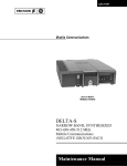
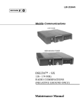
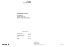
LBI-31511B
MAINTENANCE MANUAL
403-430 MHz & 450-512 MHz, DELTA-S NARROWBAND
TWO WAY FM RADIO
SERVICE SECTION
TABLE OF CONTENTS
Page
DESCRIPTION . . . . . . . . . . . . . . . . . . . . . . . . . . . . . . . . . . . . . . . . . . .
Front Cover
INITIAL ADJUSTMENT . . . . . . . . . . . . . . . . . . . . . . . . . . . . . . . . . . . . . .
Front Cover
MAINTENANCE . . . . . . . . . . . . .
PREVENTIVE MAINTENANCE . .
DISASSEMBLY . . . . . . . . . . . .
PA TRANSISTOR REPLACEMENT
REMOVING IC’s . . . . . . . . . . .
REPLACING CHIP COMPONENTS
.
.
.
.
.
.
.
.
.
.
.
.
.
.
.
.
.
.
.
.
.
.
.
.
.
.
.
.
.
.
.
.
.
.
.
.
.
.
.
.
.
.
.
.
.
.
.
.
1
1
1
2
2
2
PROGRAMMING AND ALIGNMENT . . . . . . . . . . . . . . . . . . . . . . . . . . . . . .
2
SERVICE TIPS . . . . . . . . . . . . . . . . . . . . . . . . . . . . . . . . . . . . . . . . . . . .
3
TEST AND TROUBLESHOOTING PROCEDURES . . . . . . . . . . . . . . . . . . . . . . .
4
TRANSMITTER ALIGNMENT . . . . . . . . . . . . . . . . . . . . . . . . . . . . . . . .
7
RECEIVER ALIGNMENT . . . . . . . . . . . . . . . . . . . . . . . . . . . . . . . . . . . . .
11
RECEIVER AUDIO AND SQUELCH WAVEFORM CHECKS . . . . . . . . . . . . . . . . . .
14
MECHANICAL LAYOUT . . . . . . . . . . . . . . . . . . . . . . . . . . . . . . . . . . . . .
15
INTERCONNECTION DIAGRAMS . . . . . . . . . . . . . . . . . . . . . . . . . . . . . . . .
17
DESCRIPTION
The service section of this manual contains the diagnostic
routines, and other maintenance information to service this
radio. The service section includes:
•
•
•
•
.
.
.
.
.
.
.
.
.
.
.
.
.
.
.
.
.
.
.
.
.
.
.
.
.
.
.
.
.
.
.
.
.
.
.
.
•
•
.
.
.
.
.
.
.
.
.
.
.
.
.
.
.
.
.
.
.
.
.
.
.
.
.
.
.
.
.
.
.
.
.
.
.
.
.
.
.
.
.
.
.
.
.
.
.
.
.
.
.
.
.
.
.
.
.
.
.
.
.
.
.
.
.
.
.
.
.
.
.
.
.
.
.
.
.
.
.
.
.
.
.
.
.
.
.
.
.
.
Alignment procedures for the transmitter and receiver.
Troubleshooting flow charts and waveforms.
INITIAL ADJUSTMENT
System interconnections.
Mechanical layout.
Disassembly procedures.
After the radio has been installed (as described in the
Installation Manual), the following adjustments should be
made by a certified electronics technician.
Replacement of IC’s chip capacitors and resistors.
Printed in U.S.A.
LBI-31511
LBI-31511
TRANSMITTER ADJUSTMENT
The adjustment for the transmitter includes measuring the
forward and reflected power and adjusting the antenna length for
optimum ratio, then setting the transmitter to rated power output.
Next, measure the frequency and modulation and record these
measurements for future reference. For the complete transmitter
adjustment, refer to the Alignment Procedure (see Table of
Contents).
DISASSEMBLY
MAINTENANCE
•
PREVENTIVE MAINTENANCE
To ensure high operating efficiency and to prevent mechanical and electrical failures from interrupting system operations,
routine checks should be made of all mechanical and electrical
parts at regular intervals. This preventive maintenance should
include the checks as listed in the table of Maintenance Checks.
INTERVAL
MAINTENANCE CHECKS
6 Months
CONNECTIONS - Ground connections and connections to the voltage source should be periodically
checked for tightness. Loose or poor connections to the power source will cause excessive voltage
drops and faulty operation. When ground connections are not made directly to the battery, the
connection from the battery to vehicle chassis must be checked for low impedance. A high impedance
may cause excessive voltage drips and alternator noise problems.
1.
Unlock the radio.
2.
Pull down the handle.
3.
Pull the radio forward and lift radio out of mounting
place -- if desired.
4.
Pry up the front of top cover and lift the cover off.
5.
To gain access to the bottom side, pull the radio all
the way out of the mounting frame and remove the
four mushroom shaped feet using a #30 Torx® screwdriver.
As
Required
X
NOTE
With the top cover removed all components on the
PA and TRS board are accessible for tuning. The PA,
IF, and synthesizer/exciter covers must be removed
to expose components.
X
ELECTRICAL SYSTEM - Check the voltage regulator and alternator or generator periodically to
keep the electrical system within safe and economical operating limits. Overvoltage is indicated when
the battery loses water rapidly. Usage of 1 or 2 ounces of water per cell per week is acceptable for
batteries in continuous operation. A weak battery will often cause excessive noise or faulty operation.
Figure 1 - Disassembly - Bottom View
MECHANICAL INSPECTION - Since mobile units are subject to constant shock and vibration, check
for loose plugs, nuts, screws and parts to make sure that nothing is working loose. Be sure that all
screws are properly torqued.
X
ANTENNA - The antenna, antenna base and all contacts should be kept clean and free from dirt or
corrosion. If the antennas or its base should become coated or poorly grounded, loss of radiation and
a weak signal will result.
X
•
ALIGNMENT - The transmitter and receiver meter readings should be checked periodically, and the
alignment "touched up" when necessary. Refer to applicable Alignment Procedure and troubleshooting sheet for typical voltage readings.
X
FREQUENCY CHECK - Check transmitter frequency and deviation. Normally, these checks are
made when the unit is first put into operation, after the first six months and once a year thereafter.
X
Copyright© September 1985, General Electric Company
To gain access to the unit for servicing:
To remove the TRS board:
1.
Remove the bottom cover.
2.
Remove the eleven retaining screws at (A) (Figure 1)
securing the circuit board to the main frame.
3.
Remove two retaining screws (B) securing systems
connector J601 to front casting.
4.
Unsolder the two feed through capacitor terminals
(E) on printed wire pattern.
5.
Turn over the radio and remove the three retaining
screws (D) (Figure 2) securing the audio bridge amplifier, U601 and U602, and the 5 and 9 volt regulators U702 and Q705 to the side of chassis.
6.
To remove the front end shield, remove the 20 retaining screws securing the shield to the front end casting
and remove.
7.
To remove the synthesizer shield, remove the seventeen retaining screws securing the shield to the synthesizer top casting.
Figure 2 - Disassembly - Top View
1
LBI-31511
•
To replace TRS board:
1.
•
LBI-31511
PA TRANSISTOR REPLACEMENT
Perform above procedures in reverse order.
WARNING
To remove the PA board:
1.
Remove the three retaining screws (G) securing the
PA filter cover to the main frame.
2.
Remove the eight retaining screws (F) from around
the edge of the PA board.
3.
Remove the two retaining screws (H) securing the
antenna connector to the main frame.
4.
Loosen the retaining screw (J) securing the pass
transistor to the side of the PA chassis compartment.
5.
Remove the retaining screws (K) securing the PA
transistors to the main frame.
6.
Turn the radio over and remove the nut and washer
from the stud of PA transistor Q1.
The RF Power Transistors used in the transmitter
contain Beryllium Oxide, a TOXIC substance. If the
ceramic or other encapsulation is opened, crushed,
broken or abraded, the dust may be hazardous if
inhaled. Use care in replacing transistors of this type.
•
To replace the PA RF transistors:
1.
Unsolder one lead at a time with a 50 watt soldering
iron. Use a scribe or X-acto®knife to hold the lead
away from the printed circuit board until the solder
cools.
2.
Remove retaining screws and lift out the transistor.
Remove any old solder from the printed circuit board
with a vacuum desoldering tool. Special care should
be taken to prevent damage to the printed circuit
board runs because part of the matching network is
included in the base and collector runs.
3.
Trim the new transistor leads (if required) to the lead
length of the removed transistor. The letter "C" on
the top of the transistor also indicates the collector.
NOTE
Torque #8 nut on Q1 to 6 inch pounds when replacing.
7.
8.
Unsolder the two power feed through capacitors at
(L).
Note the position of the copper washer spacer under
transistor Q1. Be sure that this spacer is in place when
replacing the board.
5.
Solder the leads to the printed circuit pattern. Start at
the inner edge of mounting hole and solder the remaining length of transistor lead to the board. Use
care not to use excessive heat that causes the printed
wire board runs to lift up from the board. Check for
shorts and solder bridges before applying power.
CAUTION
To replace the PA board:
1.
2
Apply a coat of silicon grease to the transistor mounting surface. Place the transistor in the mounting hole.
Align the leads as shown on the Outline Diagram.
Then replace the transistor mounting screws using
moderate torque.
Carefully lift the PA board up off the pins extending
upward from the TRS board.
NOTE
•
4.
Perform the above procedures in reverse order, being
careful to realign all interconnecting pins and
sleeves. Be sure the antenna gasket between the
antenna jack and front casting is positioned properly.
Failure to solder the transistor leads as directed may
result in the generation of RF loops that could damage
the transistor r may cause low power output.
REMOVING IC’s
Removing IC’s (and most other soldered-in components)
can be easily accomplished by using a vacuum desoldering tool.
To remove an IC, heat each lead separately on the solder side and
remove the old solder with the desoldering tool.
3.
Remove excess solder with a vacuum solder extractor.
4.
Carefully remove the epoxy adhesive and excess flux
to prevent damage to the printed board.
To Replace Chip Components
1.
Using as little solder as possible, "tin" one end of the
component and one of the pads on the printed wiring
board.
2.
Place the "tinned" end of the component on the "tinned"
pad on the board and simultaneously touch the component and the pad with a well "tinned" soldering iron
while pressing the component down on the board.
3.
Place the "tinned" soldering iron on the other end of the
component and the pad simultaneously. Apply solder
to the top of the end of the component until the solder
starts to flow. Use as little solder as possible while
getting a good joint.
4.
After the component has cooled, remove all flux from
the component and printed wiring board area with
alcohol.
CAUTION
The CMOS Integrated Circuit devices used in this equipment can be
destroyed by static discharges. Before handling one of these devices,
the serviceman should discharge
himself by touching the case of a bench test instrument that has a 3-prong power cord connected to an
outlet with a known good earth ground. When soldering or desoldering a CMOS device, the soldering iron
should also have a 3-prong power cord connected to
an outlet with a known good earth ground. A batteryoperated soldering iron may be used in place of the
regular soldering iron.
REPLACING CHIP COMPONENTS
Replacement of chip components should always be done
with a temperature-controlled soldering iron, using a controlled
temperature of 700°F (371°C). However, do NOT touch black
metal film of the resistors or the ceramic body of capacitors with
the soldering iron.
NOTE
The metallized end terminations of the parts may be
touched with the soldering iron without causing damage.
To Remove Chip Components
1.
Grip the component with tweezers or needle nose pliers.
2.
Alternately heat each end of the chip in rapid succession
until solder flows, and then remove and discard the
chip.
PROGRAMMING AND ALIGNMENT
The following procedure describes how to change the frequencies in the radio EEPROM(S) for new user frequencies.
Also included is an alignment procedure guide to assist you in
aligning the radio after the frequencies have been changed. The
alignment procedure should be performed in the order given and
it must be performed prior to putting the radio back in service.
PROGRAMMING
The DELTA-S UHF Narrowband radio may be programmed
using the TQ-2310 Suitcase Programmer, the 4EX22A10 Hand
Programmer or by a Personal Computer. The procedures for
using the programmers are covered in detail in LBI-31263 (TQ2310) and LBI-31275 (4EX22A10). TQ-3334 provides the software and programming instructions for programming with a PC.
When programming the radio, consideration must be given
to the individual band split for the T/R/S board. See the Programming tips on the following page and the individual band splits
listed below.
LBI-31511
LBI-31511
BAND
SPLIT
T/R/S BOARD
(NEG. GRD. ONLY)
T/R/S BOARD
(FLOATING GRD.)
450-470 MHz
470-494 MHz
494-512 MHz
403-430 MHz
450-470 MHz
470-494 MHz
494-512 MHz
403-430 MHz
19D901620G1 (Tin Cont.)
19D901620G2 (Tin Cont.)
19D901620G3 (Tin Cont.)
19D901620G4 (Tin Cont.)
19D901620G5 (Gold Cont.)
19D901620G6 (Gold Cont.)
19D901620G7 (Gold Cont.)
19D901620G8 (Gold Cont.)
19D900920G1
19D900920G2
19D900920G3
19D900920G4
MICROCOMPUTER SOFTWARE (U705)
The latest software package is a 19A703244P23 or a
19A703868G5; replacing the following packages:
Narrowband
When servicing the radio be sure that no solder buildup
has occurred on the chassis or shield.
When servicing the microcomputer/synthesizer circuitry
it is sometimes desirable to force the microcomputer into
specific operating modes. Following are some tips that allow
you to initiate these modes.
To assure a high degree of resistance to microphonics be
sure to replace exactly, all hardware removed. Be sure that all
mounting screws are properly torqued and shields in place.
Refer to Mechanical Layout Diagram.
•
•
4.
Tune the exciter.
5.
Adjust transmitter power amplifier.
6.
Set the reference oscillator frequency (one setting for
both transmit and receive).
To force the microcomputer to continually try to
reload the synthesizer. This mode will enable you to
check the serial data, clock, channel change pulse and
enable signals to the synthesizer. Grounding the lock
detect line into the microcomputer at U703-8.
To stop the microcomputer from running, disable the
watchdog timer by shorting the collector and emitter
of Q714 and ground the single step line at U705-5.
19A703244P21,22
19A703868G2-4
PROGRAMMING TIPS
When programming with the Suitcase Programmer or a
Personal Computer, Jumper P707 (if present on Negative
Ground System Boards only) must be removed. If programming
the S950/S990 Control Unit for download to the radio, P703 on
the rear of Control Unit must be disconnected to isolate Advance
Change Pulse Line.
When the 4EX22A10 Hand Programmer, Jumper P706
(Negative Ground T/R/S Boards) must be removed (to disconnect D720), or lift one end of D720 on Floating Grd T/R/S
Boards.
ALIGNMENT
After the radio has been programmed with new user frequencies, the radio re-alignment procedure is as follows:
UNDER SYNTHESIZER AND TRANSMITTER
ALIGNMENT PROCEDURE
1.
Check 9 volt regulator.
2.
Adjust the synthesizer transmitter VCO.
3.
Adjust the synthesizer receiver VCO.
1.
Adjust local oscillator-buffer injection.
2.
Adjust front end.
3.
Adjust IF selectivity.
4.
Adjust FM detector/audio pre-amp.
NOTE
Loose or rubbing parts, especially in the VCO area
are particularly sensitive and can cause microphonics. Again be certain all hardware is properly installed
and torqued.
MICROPHONICS
Wideband
UNDER RECEIVE ALIGNMENT SECTION
19A703244P10
19A703241G3-8
MICROCOMPUTER
TEST FREQUENCIES
Synthesized radios tend to be sensitive to shock and
vibration, creating microphonics. The construction of the
DELTA-S, radio with its die cast aluminum frame, cast shields,
and multiple board mounting screws, provides a high degree
of immunity. When removing either printed circuit board or
the shields, note the exact location and position of all mounting
hardware including rubber padding and bracket (if included).
If the EEPROM is not custom programmed to the customers specified personality, then a standard test program is provided. The EEPROM is programmed on channels 1 through
16 including tone and digital Channel Guard and carrier control timer. Table 1 identifies the programmed test frequencies.
SERVICE TIPS
CHANNEL GUARD BOARD
When servicing the transmit/receive/synthesizer board it
may be helpful to remove and relocate the Channel Guard board.
Both the Channel Guard board and Channel Guard extender may
be removed and set aside during servicing. While servicing the
radio install P608 to connect VOL/SQ/HI.
NOTE
Typical voltage readings are provided on the Schematic
Diagram for reference when troubleshooting.
3
LBI-31511
LBI-31511
TROUBLESHOOTING PROCEDURE
(Cont.)
TYPICAL PERFORMANCE INFORMATION
TYPICAL PERFORMANCE INFORMATION
SIGNAL LEVELS
RADIO CONNECTOR IDENTIFICATION
SIGNAL
CAS
RUS
Sq Dis, Input
CCT Sq Dis, Input
TX Enable
PTT, Input
INDICATION
High Level
Low Level
High Level (RX Un-sq)
Low Level (RX Squelched)
Low Level (RX Mute/PTT)
Pulled low (RX unsquelched)
Logic Low (Sq. Dis)
Logic High (Sq)
RX Un-Sq
Logic Low
Logic High
Logic Low
Logic High
Logic Low
Logic High
FUNCTION
P701
P702
P703
P704
P705
5V
9V
9V
9V
9V
0.6 Vdc
0
Vdc
2.4 Vdc
0.14 Vdc
0.35 Vdc
5.5 Vdc
2.0 Vdc
9.0 Vdc
1.0 Vdc
13 Vdc
SCALE
TYPICAL
READING
D
IF AMP
1V
0.75
H
RX INJ
1V
0.55
TRANSMITTER QUICK CHECKS
75
70
TX 90, RX 80
TX 45, RX 75
TX 40, RX 55
–
–
Connect red system metering plug to J602, system metering.
Connect black plug of GE Test Set to RF Metering jack J101. Set polarity to "+" and voltage range to the 1 volt
position (Test 1).
EXCITER
VOLTAGE
CONTROL
DESCRIPTION
J602-3
9.0 ±0.05 Vdc
J602-2
13.2 Vdc (A+)
J202
3.0-7.5 Vdc
J353
0.7 VPP
Reference Osc. Output (high
impedance)
J352
5.5 Vdc (Nominal)
Reference Oscillator
compensation line voltage
J712
5.0 Vdc
VCC to Microcomputer
R703
9 Volt Regulator
TEST 1
C220 (RX)
L209 (TX)
PROBABLE CAUSE
RF METERING J101
EXCITER READINGS
RANGE
POSITION
TEST
POS.
METERING
JACK J101
FUNCTION
A
J101-10
AMPL-1
METERING READINGS
METER TYPICAL
SCALE READING
0-1
0.2V
VCO Control Voltage
(See Synth Align)
(Cont.)
4
TEST POS FUNCTION
TYPICAL CURRENT/mA
TEST POINT DATA (Typical)
TEST POINT
J601
J602
J603
J711
J101
P401
P404
P451
P102
P101, P103
P706
P707
J1
P612
P605
P608
P610
P402
P403
Front Connector
Systems Metering
Option Connector
PROM Program Plug
RF Metering
RX Input
IF Input
RX Inj.
Exciter Input
Exciter Output
Hand Programmer Enable
Program Disable
TX PA Metering
VG Interface
Fixed Squelch
Channel Guard
Aux Audio
DPTT
IGN A+
9.0 Vdc
0.15 Vdc
9.0 Vdc
0.15 Vdc
CURRENT REFERENCE CHART
SERVICE
PLUG
RECEIVER READINGS SYSTEM JACK, J602
VOLTAGE LEVEL
HIGH
Q101
Shorted
R101,
Open
R 1 03
LOW
Q101 Open; R103, R105,
O p en ;
L 10 3
O p en ;
O sc i ll a to r /
B u f fe r
Defective
TEST 1
B
J101-9
TRIPLER
0-3
0.2V
Q102
Defective; R107
Open
Q102 Shorted; R110 Open;
L104, L105, and associated
c i r c ui t s , d ef ec t iv e o r
improperly tuned.
TEST 1
C
J101-8
AMPL-3
REL PWR
OUT
0-1
0.5V
H e li c al C o i l
L114
Shorted Or
Mis-tuned
Q103 OR Q104 defective.
Check resistors, capacitors
around Q103 and Q104.
Helical coils L107, L108
m is-tuned or defective.
D 1 0 1 an d a s s oc ia t ed
metering circuits defective.
LBI-31511
LBI-31511
TROUBLESHOOTING PROCEDURE
(Cont.)
PA QUICK CHECKS
–
–
Connect red system metering plug to J602, system metering.
Connect black plug of GE Test Set of RF Metering jack J1 of PA. Set polarity to "+" and voltage range to the 1 volt
position (Test 1).
PA TROUBLESHOOTING PROCEDURE
When troubleshooting the transmitter check for typical meter readings for the exciter, J101, and the power amplifier JACK,
J1. Typical readings for the various test positions and test points are given in the charts below.
NOTE
SYMPTOM
PROCEDURE
ANALYSIS
Little or No
RF Output
Key transmitter and check J1-10 (Pos A) for +0.5
V (exciter output).
Refer to Schematic Diagram and verify voltage
readings.
Unkey transmitter and check Q105-C for +9.0
Vdc.
Verify +9.0 volt supply. Check R124 and L117.
Check DC voltages on Q101-Q105.
If voltages are incorrect, check L103, L106, L110,
L112, L117 and all resistors for each stage. Check
R106, R110, R114, R118, R119 and R124. Check
Q101-Q105. Replace components if defective.
Disconnect P102 on Exciter and measure RF
output of synthesizer.
No RF present: see Synthesizer Troubleshooting
Procedure.
High exciter output.
Key transmitter and monitor voltage at J101-9
(Pos B Tripler). Voltage should increase.
RF present: reconnect P102 and proceed to next step.
Excessive voltage drop
in power cable.
Monitor J101-8 (Pos C) and key transmitter.
Voltage should increase.
If voltage does not increase check Q116-Q118, L106
and associated components.
Disconnect P103 on exciter and measure RF
output power from exciter. Should be 0.5 watts or
more.
If voltage does not increase, check Q103, Q104 and
associated components. Check D101 and associated
metering circuitry. Finally, check both helical filters.
Regulated +5 Vdc and +9 Vdc can be opened by P701 thru P705 to facilitate troubleshooting.
POWER AMPL METERING J1
PA JACK READINGS
80, 90
100W
35, 40
50W
65,
75W
TYPICAL TYPICAL TYPICAL
TEST METERING FUNCTION
SCALE
READING READING READING
POS.
POINT
MEASURED
A
J1-10
RF DRIVE
0-1 V
0.5 V
0.5 V
0.5V
B
J1-9
CONTROL
VOLTAGE
0-15V
4
V
4.5 V
7.5V
C
J1-8
TX A+
0-15V
12.5V
12.5V
12.5V
E
J1-6
PA
CURRENT
0-30A
15
---
11A
F
J1-5
DRIVER
CURRENT
0-15A
5
A
A
8A
4A
METER
READING
PROBABLE CAUSE
HIGH
LOW
L o w e xc i t e r o ut p ut .
Realign or repair exciter.
L o w ex cit er
output
RF
output
excessively
high. Be sure
a n t e nn a i s
properly
matched to 50
ohms.
RF output low.
100 WA TT
PA
C h e ck
A1Q5
a nd
A1Q6.
Be
sure antenna
i s p ro p e r ly
matched to 50
ohms.
100 WATT PA A1Q5
and
A1Q6
ha ve
excessive gain. RF gain.
RF output set too low.
40 WATT PA
RF
output
power
is
excessive. Be
sure antenna
i s p ro p e r ly
matched to 50
ohms.
40 WATT PA Low RF
output.
If exciter output is low, check Q105 and associated
circuitry. Also check 2nd helical filter including L114
and L115. Retune exciter if needed.
If output power is correct be sure P101 is soldered
securely and that it mates properly with the contact on
the power amplifier.
(Cont.)
5
LBI-31511
TEST PROCEDURE
These Test Procedures are designed to help you to service
a receiver that is operating -- but not properly. The problems
encountered could be low power, poor sensitivity, distortion,
limiter not operating properly and low gain. By following the
sequence of test steps starting with Step 1, the defect can be
quickly localized. Once the defective stage is pin-pointed,
refer to the "Service Check" listed to correct the problem.
Additional corrective measures are included in the Troubleshooting Procedure. Before starting with the Receiver Test
Procedures, be sure the receiver is tuned and aligned to the
proper operating frequency.
STEP 1
AUDIO POWER OUTPUT
AND DISTORTION
A. Apply a 1000 microvolt, on-frequency test signal
modulated by 1,000 Hz with ±3.0 kHz deviation to
antenna jack J2.
Disconnect speaker lead pins from J1A-36 and 37
on rear of control unit. Connect a 4.0 ohm, 15 watt
load resistor across system metering jack J602-6
and 7 on the TRS board.
Distortion Analyzer
Signal Generator
Connect the isolation transformer input across the
resistor. Connect the isolation transformer output to
the Distortion Analyzer (See Figure 5).
6 dB attenuation pad
Audio Isolation Transformer
PRELIMINARY ADJUSTMENTS
NOTE
C. Adjust the VOLUME control for 12 watts output
6.93 VRMS using the Distortion Analyzer as a voltmeter.
D. Make distortion measurements according to manufacturer’s instructions. Reading should be less than
3%. If the receiver sensitivity is to be measured, leave
all controls and equipment as they are.
C. Place the RANGE switch SET LEVEL position (filter
out of the circuit) and adjust the input LEVEL control
for a +2 dB reading on a mid range (30%).
D. Set signal generator output to 0.3 µV. Switch the
RANGE control from SET LEVEL to the distortion
range Readjust Distortion Analyzer SET LEVEL as
required until a 12 dB difference (+2 dB to -10 dB) is
obtained between the SET LEVEL and distortion range
positions (filter out and filter in).
E. The 12 dB difference (Signal plus Noise and Distortion
to noise plus distortion ratio) is the "usable" sensitivity
level. The sensitivity should be less than rated 12 dB
SINAD specifications with an audio output of at least
6 watts (49 Volts RMS across 4.0 ohm receiver load
using the Distortion Analyzer as a Voltmeter).
Leave all controls as they are and all equipment connected if the Modulation Acceptance Bandwidth test is
to be performed.
SERVICE CHECK
F.
Audio Gain (Refer to Receiver Troubleshooting Procedure.)
G. FM Detector Alignment (Refer to Receiver Alignment.)
6
B. Place the RANGE switch on the Distortion analyzer in
the 200 to 2000 Hz distortion range position (1000 Hz
filter in the circuit). Tune the filter for minimum reading
or null on the lowest possible scale (100%, 30%, etc.)
F.
If the distortion is more than 3%, or maximum
audio output is less than 12 watts, make the following checks:
E. Battery and regulator voltage --- low voltage will
cause distortion. (Refer to Receiver Schematic Diagram for voltages.)
Unsquelch the receiver.
A. Apply a 1000 microvolt, on-frequency signal modulated by 1000 Hz with 3.0 kHz deviation to J601.
SERVICE CHECK
These procedures are written around the Heathkit
Distortion Analyzer. If a Distortion Analyzer other
than the Heath IM-12 is used, measure the sensitivity
and modulation acceptance bandwidth in accordance
with manufacturer’s instructions.
1.
If STEP 1 checks out properly, measure the receiver
sensitivity as follows:
STEP 3
MODULATION ACCEPTANCE BANDWIDTH (IF BANDWIDTH)
If STEPS 1 and 2 check out properly, measure the
bandwidth as follows:
Measure Audio Power Output as follows:
TEST EQUIPMENT REQUIRED
4 ohm resistor (15 watt minimum)
STEP 2
USABLE SENSITIVITY
(12 dB SINAD)
TEST PROCEDURE
B. With 12 Watt Speaker
•
•
•
•
•
LBI-31511
RECEIVER TEST PROCEDURE
If the sensitivity level is more than the rated 12 dB
SINAD, check the alignment of the RF stages as
directed in the Alignment Procedure.
A. Set audio to 10% of rated output.
B. Set the Signal Generator output for twice the microvolt
reading obtained in the 12 dB SINAD measurement.
C. Set the Range control on the Distortion Analyzer in the
SET LEVEL position (1000 Hz filter out of the circuit),
and adjust the input LEVEL control for a +2 dB reading
on the 30% range.
D. While increasing the deviation of the Signal Generator,
switch the RANGE control from SET LEVEL to distortion range until a 12 dB difference is obtained between the SET LEVEL and distortion range readings
(from +2 dB to -10 dB).
E. The deviation control reading for the 12 dB difference
is the Modulation Acceptance Bandwidth of the receiver. It should be more than ±7.0 kHz.
SERVICE CHECK
If the Modulation Acceptance Bandwidth test does not
indicate the proper width, check the synthesizer frequency and then refer to the Alternate IF Alignment
Procedure.
LBI-31511
LBI-31511
TRANSMITTER ALIGNMENT
(Cont.)
TEST PROCEDURES
These Test Procedures are designed to assist you in servicing a transmitter that is operating -- but not properly. Once a defect is
pin-pointed, refer to the Transmitter Troubleshooting Procedure. Before starting, be sure that the transmitter is tuned and aligned to
the proper operating frequency.
TEST PROGRAMMING
In DELTA-S radios, in which the EEPROM is not custom programmed, the EEPROM may be programmed with the
personality similar to the ones shown in Table 1 below. See data on production tag with radio for exact data.
CAUTION
Table 1 - Programmed Test Frequencies
Before bench testing the radio, be sure or the output voltage characteristics of your bench power supply.
To protect the transmitter power output transistors from possible instant destruction, the following input voltages must not
be exceeded:
Transmitter unkeyed:
20 Volts
Transmitter keyed (50 ohms resistive load):
18 Volts
Transmitter Keyed (no load or non-resistive load):
14 Volts
These voltages are specified at the normal vehicle battery terminals of the radio and take the voltage drop of standard cables
into account. The voltage limits shown for a non-optimum load is for "worst case" conditions. For antenna mismatches likely
to be encountered in practice, the actual limit will approach the 18 Volt figure.
FREQUENCY
SPLIT
CHANNEL
NO.
TRANSMIT
FREQUENCY
RECEIVE
FREQUENCY
CHANNEL GUARD
ENC/DEC
CCT
450-470 MHz
1
2
3
4
5
6
7
461.025
467.025
461.025
455.025
450.000
470.000
461.000
461.050
462.050
461.050
460.050
460.025
469.750
460.750
71.9
023
------71.9
---
----30 SEC
---------
470-494 MHz
1
2
3
4
5
6
7
483.8875
489.8875
483.8875
477.8875
470.000
494.000
485.000
483.050
484.050
483.050
482.050
470.050
493.750
484.750
71.9
023
------71.9
---
----30 SEC
---------
494-512 MHz
1
2
3
4
5
6
7
503.000
509.000
503.000
497.000
494.000
512.000
503.000
502.975
503.975
502.975
501.975
501.975
511.750
502.750
71.9
023
------71.9
---
----30 SEC
---------
403-430 MHz
1
2
3
4
5
6
7
413.025
419.025
413.025
407.025
403.000
430.000
414.000
413.050
414.050
413.050
412.050
403.050
429.750
413.750
71.9
023
------71.0
---
----30 SEC
---------
Routine transmitter tests should be performed at EIA Standard Test Voltages of (13.6 Vdc for loads of 6 to 16 amperes; 13.4
Vdc for loads of 16 to 36 amperes). Input voltages must not exceed the limits shown, even for transient peaks of short
duration.
Many commonly used bench power supplies cannot meet these requirements for load regulation and transient voltage
suppression. Bench supplies which employ "brute force" regulation and filtering (such as Lapp Model 73) may be usable
when operated in parallel with a 12 volt automotive storage battery.
(Cont.)
7
LBI-31511
TRANSMITTER FREQUENCY
ADJUSTMENT
First check the frequency to determine if any adjustment
is required. The frequency should be set with a frequency
meter or counter with an absolute accuracy that is 5 to 10 times
better than the tolerance to be maintained, and with the entire
radio as near as possible to an ambient temperature of 25°C
(77°F).
The oscillator frequency should be set at 25°C ambient
temperature. In the range of 15°C to 40°C, if the frequency
deviates more than ±1 PPM, it may be reset to ±1 PPM,
respectively.
PROCEDURE
Select a center frequency channel. Disable Channel
Guard if present.
2.
Preset R366 fully counterclockwise and R22 on
Channel Guard board (if present) to the center of its
range.
3.
4.
Refer to Figures 3 and 4 Frequency Correction Factor.
5.
Adjust L352 to set the transmit frequency while monitoring RF output jack J2 through a 30 dB decoupler. If adjusting
L352 does not result in setting transmitter on frequency, remove synthesizer top cover, set L352 two turns from top of
coil form, then adjust course frequency control L354 on frequency. Replace cover. This procedure would be necessary if
repair/replacing parts in oscillator circuit.
MODULATION LEVEL
ADJUSTMENT
The MOD ADJUST controls are adjusted to the proper
setting before shipment and normally do not require readjustment. This setting permits approximately 75% modulation for
the average voice level. The audio peaks which would cause
overmodulation are clipped by the modulation limiter. The
limiter, in conjunction with the de-emphasis network, instantaneously limits the slope of the audio wave to the modulator,
thereby preventing overmodulation while preserving intelligibility.
An audio oscillator (GE Model 4EX6A10)
2.
Deviation Monitor
3.
An output meter or a VTVM
4.
GE Tes t Set Mode l 4E X3A11 T est Cable
19C850590G1
Apply a 1 kHz tone at 1.0 VRMS to mic input jack
J603-17. Connect deviation monitor to RF output
jack J2 through a 30 dB decoupler. Set DEVIATION
ADJUST R237 for rated deviation. ±3.75 kHz with
Channel Guard or ±4.5 kHz without Channel Guard.
TEST EQUIPMENT REQUIRED
Select a channel with Channel Guard nearest the
center frequency and adjust R22 on the Channel
Guard option board to ±0.65 kHz (tone or digital
Channel Guard).
When a radio is factory programmed for less than 16
channels, channel 16 is programmed for transmit and receive
center tune frequency.
•
Audio Oscillator
•
AC Voltmeter
•
Oscilloscope
•
Deviation Monitor
AUDIO AC VOLTAGES
1.
Apply a 400 Hz tone through a 100 µF capacitor to
J603-15. Set output level to obtain a deviation of ±2.0
kHz. Note and maintain this voltage level while
switching the output frequency to 10 Hz. Adjust REF
OSC Deviation Control R366 starting from the fully
clockwise position for ±2.0 kHz deviation. Remove
the modulation.
ACCESSING CENTER TUNE FREQUENCY
Connect audio oscillator output across J603-10 (MIC HI) and J603-16 (MIC LO).
SCOPE
SETTING
U301-7
C301-1
HORIZONTAL
200 µ SEC/DIV
200 µ SEC/DIV
VERTICAL
2 VOLTS/DIV
2 VOLTS/DIV
SET AUDIO OSCILLATOR AT 1000 Hz WITH OUTPUT OF
1.0 VRMS. MODULATION ADJUSTED FOR 4.5 kHz
DEVIATION. NOTE: AN RMS OR PEAK READING
VOLTMETER WILL READ 1/2 TO 1/3 OF PEAK-TO-PEAK
READINGS.
AUDIO SENSITIVITY
1.
Connect audio oscillator output across J603-10 (MIC HI) and J603-16 (MIC LO). Adjust output for 1000 Hz at 1.0 VRMS.
2.
Reduce generator output until deviation falls to 3.0 kHz for radios without Channel Guard or to 2.25 kHz for radios with
Channel Guard. Voltage should be less than 120 millivolts.
To access center tune frequency use available control unit
and select channel 16.
NOTE
Under normal operation, in radios built prior to January 1989, the microcomputer will not access this
channel. The following tests accesses Channel 16 to
assure its availability for tuning purposes.
1.
Apply +12 Vdc through a 10K resistor to J6043, then turn the radio on. This tells the microcomputer to always access Channel 16.
2.
To select the transmit center tune frequency,
press the PTT switch (J601-11). Release the
PTT switch to select the receiver center frequency.
3.
To exit this mode remove power from J604-3
and momentarily remove power from the radio.
TEST EQUIPMENT
1.
AUDIO CHECK
1.
NOTE
8
LBI-31511
TRANSMITTER ALIGNMENT
Figure 3 - Correction Factor in Freq. Setting
Figure 4 - Correction Factor in Freq. Setting
LBI-31511
TEST CABLE
TRANSMITTER ALIGNMENT
LBI-31511
SYNTHESIZER AND TRANSMITTER ALIGNMENT
TEST EQUIPMENT REQUIRED
1.
Watt meter, 50 ohm (capable of measuring 150 watts & 1 watt)
2.
Digital Voltmeter
3.
RF Frequency Counter
4.
RF Voltmeter
5.
Power Supply, 13.8 Vdc regulated
6.
GE Test Set, 4EX3A11 with Test Set Adapter 19C850590G1
7.
Tuning Tool 19B800716P2
PRELIMINARY CHECKS AND ADJUSTMENTS
NOTE
Refer to Figure 5 for location of tuning adjustment controls.
Connect black plug of GE Test Set to RF Metering jack J101. Connect red system metering plug to J602, system metering.
Set polarity to "+" and voltage range to the 1 volt position (Test 1).
NOTE
Before aligning or making any adjustments to the transmitter, be sure that the output of the 9 volt regulator is set for
9.0 ±0.05 Vdc. Monitor J602-3 with a digital voltmeter and adjust R703.
ALIGNMENT PROCEDURE
Synthesizer TX and RX Vco
The TX and TX VCO voltage adjustments are described by the following steps 1-5. After the lock detect light D713 goes
out (step 1 and 3) each VCO is adjusted after selecting the appropriate channel for the maximum reading indicated.
If the light is not out, all readings are meaningless.
As long as the highest operating frequency (VCO voltage) does not exceed the maximum meter reading and the lowest
operating frequency (VCO voltage) is not less than the minimum meter reading, the adjustment is proper.
When the two frequency spread is minimal it is acceptable to center tune the VCO voltage between the maximum and
minimum meter readings.
If the highest operating frequency is at the low end of the frequency split (example 451.025 MHz on the 450-470 MHz split),
the VCO reading may never reach the maximum. Therefore adjust the lowest operating frequency to a VCO voltage above the
minimum reading.
19C850590G1
(19C850593, Rev. 4)
9
LBI-31511
LBI-31511
TRANSMITTER ALIGNMENT
SYNTHESIZER & TRANSMITTER ALIGNMENT
METERING POSITION
STEP
TUNING
GE TEST MULTIMETER CONTROL
SET
(- TO A-)
1.
LED D713
2.
J202
3.
LED D713
4.
J202
5.
J202
L209
L209
C220
C220
METER
READING
EXCITER/TRANSMITTER POWER AMPLIFIER (Cont.)
METERING POSITION
PROCEDURE
STEP
Light out
Select the highest frequency transmit channel. Key the transmitter and
tune L209 so that the lock detect indicator D713 goes out.
Below 7.5
Vdc
Monitor J202 with a digital voltmeter. Tune L209 for 7.5 Vdc max.
Light out
Unkey the transmitter. Select the highest frequency receive channel and
tune C220 so that the lock detect indicator D713 goes out.
10.
GE TEST MULTIMETER
SET
(- TO A-)
C
(AMPL-3)
J101-8
11.
Below 7.5
Vdc
Monitor J202 with a digital voltmeter. Tune C220 for 7.5 Vdc max.
Above 3.0
Vdc
Select the lowest frequency transmit and receive channel. Key the
transmitter and check the TX VCO voltage. Unkey the transmitter and
check the RX VCO voltage. Both readings should be above 3.0 Vdc.
12.
A
(PA
INPUT)
J1-10
TUNING
CONTROL
METER
READING
C10
0.01
Tune C10 for a dip, 0.01 volts typical. Note, after C11 is tuned, this voltage
typically will be 0.5 volts.
C11
500 mw
Tune C11 for maximum exciter power output as indicated on the wattmeter,
connected to J103-2, 4. Exciter output is typically 600 mw.
C11
Rated
Output
Power
Check exciter power output at both ends of the frequency spread. It should
be equal to or greater than 500 mw. If wattmeter to measure exciter power
is unavailable and the exciter is already connected to the PA, connect the
meter to PA board J1. Connect a 150 watt wattmeter to antenna connector
J2. Set the RF Power Adjust control for maximum power (fully clockwise).
Tune C11 for maximum meter reading on J1, position A. Check the meter
reading at both ends of the frequency spread. They should be approximately
equal. If not adjust C11 accordingly. Set RF power Adjust for rated output
power.
Monitor TX injection at J102 and RX injection at J451. (Note:
Terminate TX VCO output with 50 ohms to maintain lock with plug
removed).
Test aid for TX and RX Injection
NOTE
If more than 6.0 MHz (5.0 MHz on 403-430 MHz split) channel spacing is
required. Perform steps 13 and 14.
TX injection +5 to +15 dBm
RX injection +5 to +15 dBm
13.
EXCITER TRANSMITTER POWER AMPLIFIER
PROCEDURE
A
(PA
INPUT)
J1-10
14.
C11
Select the highest frequency channel. Key transmitter and adjust C11 so that
output power is slightly above rated power.
C10
Select lowest frequency channel. Key transmitter and adjust C10 so that
output power is slightly above rated power. Switch to highest frequency
channel and verify rated output power. If necessary repeat this step.
Preset all four tuning screws in the exciter (C8-C11) so that the tops of the tuning screws are approximately 7 mm above
the top of the casting.
Preset L103 so that the core is flush with the top of the coil form.
NOTE
*
Fo is the transmit output frequency at the antenna. The injection frequency is Fo/3 at J102.
The exciter can be isolated from the rest of the radio for tuning purposes, if desired. To isolate and set up, remove P102
and P103. Connect a (0-1 watt) wattmeter to J103-2, 4. Apply a +7 dBm at 1/3 carrier frequency signal to J102-2, 4.
REFERENCE OSCILLATOR FREQUENCY
METERING POSITION
If less than 6.0 MHz (5.0 MHz on 403-430 MHz split) channel spacing is required, select the highest transmit RF frequency.
If 6.0 to 12.0 MHz bandwidth (5.0 to 10.0 MHz on 403-430 MHz split) is required, select center frequency. (Refer to "Accessing
Center Tune Frequency" and complete steps.
STEP
GE TEST MULTIMETER
SET
(- TO A-)
TUNING
CONTROL
METER
READING
PROCEDURE
NOTE
METERING POSITION
STEP
6.
METER
READING
0.25 V
This step assumes the frequency is measured when the transmitter is first
keyed. If delayed the rapidly rising ambient temperature must be taken into
consideration. Figures 4 and 5 below show the temperature versus
frequency correction curve for the 5 PPM and optional 2 PPM reference
osc.
PROCEDURE
A
(AMPL-1)
J101-10
7.
B
(TRIPLER)
J101-9
L103
-0.45 V
Tune L103 for maximum negative meter reading (switch voltmeter for
negative reading.)
8.
B
(TRIPLER)
J101-9
C8
-0.5 V
Tune C8 for maximum meter reading.
C
(AMPL-3)
J101-8
9.
10
TUNING
GE TEST MULTIMETER CONTROL
SET
(- TO A-)
Key the transmitter. No tuning required in this step.
15.
J2
L352
Channel
O p eratin g
Frequency
Key the transmitter while monitoring the frequency at the antenna
connector J2.
Adjust L352 for the assigned channel freq.
±225 Hz for a 5 PPM radio (standard) or
±90 Hz for a 2 PPM radio (optional).
Note: The receiver injection frequency will automatically be correct.
C9
2.0 V
Tune C9 for maximum meter reading. Stop when maximum is reached.
LBI-31511
TRANSMITTER ALIGNMENT
LBI-31511
RECEIVER ALIGNMENT
RECEIVER FREQUENCY ADJUSTMENT
4.
DC couple the scope probe and adjust the controls for
0.1V per div. and 2 msec per div.
(Refer to Transmit Frequency Adjustment, no adjustment of
receive frequency is required.)
5.
Adjust the AM output level to make sure the scope is
triggering. Adjust the RF input signal level to keep the
IF passband sweep pattern just below saturation (typ. 9
µV). After using the vertical and horizontal positioning
controls to center the waveform, check for a scope
pattern similar to the one below.
ALTERNATE IF SWEEP ALIGNMENT
1.
Attach an oscilloscope probe to IF AMP. MTR. (J60210). (Refer to Figure 6).
2.
Using an HP8640B signal generator, set with an onchannel frequency, feed a 20 Hz modulating frequency
with 12 kHz of deviation into the radio at antenna jack
J2.
3.
Connect a coaxial cable between the AM output of the
HP8640B and the external 10 trigger signal on the
scope. Use NORMAL triggering.
SERVICE NOTE:
L410, L411, L412, L507 and L508
should be tuned to peak the IF passband, and any ripple should be minimized in the passband.
Figure 6 - Test Set-Up For 20 Hz Double-Trace Sweep Alignment
Figure 5 - Transmitter/Receiver Tuning & Adjustment Controls
Figure 7 - Test Set-Up, Audio Output Measurement
11
LBI-31511
LBI-31511
RECEIVER ALIGNMENT
ALIGNMENT PROCEDURE (Cont.)
RECEIVER ALIGNMENT
TEST EQUIPMENT REQUIRED (Or Equivalent)
7.
Frequency counter (Hewlett-Packard 5300B)
1.
GE Test Set 4EX3A11, 4EX8K12, or 20,000 ohmsper-volt millimeter with 1 volt scale
2.
AC Voltmeter
3.
FM Deviation Monitor
10. 4 ohm 15 watt resistor
4.
Digital Voltmeter
11. Tuning tool 19B800716P2
5.
VOM
6.
RF Signal Generator (403-512 MHz)
METERING POSITION
STEP
8.
Oscilloscope
9.
Audio Isolation Transformer (1:1) 19A116736P1 or
equivalent
TUNING
GE TEST MULTIMETER CONTROL
SET
(- TO A-)
METER
READING
PROCEDURE
3.
G
(RX INJ)
J101-4
C7
Dip
Tune C7 for a dip in Test Set reading.
4.
H
(RX MIX)
J101-3
C6, C7
L452
Peak
Tune C6 for maximum. Sequentially retune L452, C6 and C7 until there is
no further increase in meter reading.
FRONT END ALIGNMENT
5.
D
(IF AMP)
J602-10
C3
MAX
Connect RF signal generator to antenna jack J2. Set frequency to desired
receive channel or center tune frequency. Set modulation frequency to 1 kHz
and deviation to 3 kHz. Set input level to -10 dBm (70 mV).
Tune C3 for maximum indication on meter while reducing the input level
of the signal generator as required to keep the IF AMP reading from
saturating. (0.6 V typical).
PRELIMINARY CHECKS AND ADJUSTMENTS
NOTE
6.
Refer to Figure 5 for location of tuning and adjustment controls.
D
(IF AMP)
J602-10
C1, C5
C2, C4
Peak
Peak C1, C5, C2, C4 in sequence while reducing output level of signal
generator to prevent saturation.
RF SELECTIVITY
1.
NOTE
Connect the black plug from the Test Set to the RF metering jack J101. Connect red system metering plug to J602, system
metering. Set Test Set to 1 volt scale. A 20,000 ohms-per-volt multimeter may be used when the GE Test Set is not
available.
If the IF amplifiers have been aligned using the alternate sweep alignment
method, proceed to Step 9.
2.
Preset C1-C7 to maximum height above top of tuning nut (10 mm above casting).
7.
3.
Preset L509 to top of coil form and then turn clockwise 11 full turns.
Select a center frequency channel. Apply an on-frequency signal with 1 kHz
modulation to antenna jack J2. Set deviation to 3 kHz. Reduce signal level
to approximately 75% of saturated level shown on Test Set meter. While
making the following adjustments keep the signal level below saturation.
4.
Preset L451 to top of coil form, then turn 15 turns clockwise.
Tune L508, L507, L412, L411 and L410, in that order, for a peak reading.
Repeak coils until no further improvement in meter reading is noted.
5.
Preset L410, L411, L412, L507 and L508 to top of coil form and then turn clockwise 9 full turns.
6.
Apply power to radio and monitor the regulated 9 volt supply at J602-3. Adjust R703 if necessary to obtain 9 ±0.01 Vdc.
Use a digital multimeter.
8.
D
(IF AMP)
D
(IF AMP)
J602-10
J602-10
L508, L507
L410, L411
and L412
C1-C5
Maximum
(See
Procedure)
Maximum
FM DETECTOR/AUDIO PREAMPLIFIER
NOTE
The audio output is a balanced bridge circuit and requires all test equipment
connected across the speaker leads to the both AC and DC isolated from
ground.
NOTE
Before aligning the receiver or making any adjustments to the radio be sure that the output of the 9 volt regulator is set
for 9.0 ±0.1 Vdc.
Connect test equipment as shown in Figure 5.
9.
L509
10.
R629
ALIGNMENT PROCEDURE
METERING POSITION
STEP
TUNING
GE TEST MULTIMETER CONTROL
SET
(- TO A-)
METER
READING
G
(RX INJ)
J101-4
L452
Set signal generator output for 1000 µV. Set R629 and volume control to
the center position. Monitor the speaker outputs (J602-6, 7) with an AC
voltmeter. Tune quadrature coil L509 for a peak reading.
Adjust R629, audio preamplifier level for nominal 300 mV RMS at VOL/SQ
HI (J603-14).
(Cont.)
Peak
Select desired channel or center tune frequency. Set Test Set to 1 volt
scale and tune L452 for maximum reading on Test Set.
(Cont.)
12
0.35 - 0.5
VRMS
PROCEDURE
LOCAL OSCILLATOR-BUFFER INJECTION
1.
Repeak C1-C5.
LBI-31511
LBI-31511
ALIGNMENT PROCEDURE (Cont.)
METERING POSITION
STEP
GE TEST MULTIMETER
SET
(- TO A-)
TUNING
CONTROL
METER
READING
PROCEDURE
FIXED SQUELCH ADJUSTMENT (8 dB SINAD)
(EARLIER MODELS)
11.
R666
Adjust fixed squelch control R666 fully clockwise (open squelch). Adjust
input level of RF Signal Generator to produce a SINAD sensitivity reading
of 8 dB. Turn R666 fully counterclockwise (maximum squelch position) to
close squelch. Slowly readjust R666 to the position where the squelch just
opens. Verify that squelch opens at 8 ±1 dBm.
MULTI-FREQUENCY SPREAD (Multi-Frequency Radios)
(Single Frequency Radio Proceed to Step 16.)
12.
D
(IF AMP)
J602-10
C1-C3
Select a center frequency channel. Apply an on-frequency signal with 1 kHz
modulation to antenna jack J2. Set deviation to 3 kHz. Reduce signal level
to approximately 75% of saturated level shown on Test Set meter.
Detune C2 three turns clockwise or counterclockwise. Detune in direction
that will not exceed maximum or minimum tuning screw height. Tune C1
for a peak. Increase or decrease signal generator level as required to
maintain 75% of the saturated signal level. Detune C3 and then tune C2 for
a peak. Detune C4 and then tune C3 for a peak.
13.
D
(IF AMP)
14.
15.
H
(RX MIX)
16.
D
(IF AMP)
J602-10
C4, C5
Detune C5 clockwise to minimum tuning screw height. Tune C4 for a peak.
Then tune C5 to maximum tuning screw height. Tune C5 for a peak reading.
J101-3
C6
Select highest channel frequency and note meter reading. Select lowest
channel frequency and note reading. Tune C6 slightly to equalize these two
readings. If they cannot be equalized tune C6 to improve the channel with
lowest reading.
J2
C5
Adjust the frequency of the signal generator to the highest frequency
channel. Apply a modulated signal at the 0.35 µV level. Measure the SINAD
level in accordance with Step 2 of Receiver Test Procedures. If the SINAD
reading is 12 dB SINAD or less, tune C5 counterclockwise until the SINAD
reading is greater than 12 dB. Switch to the lowest frequency channel and
set the signal generator to the lowest frequency channel. Measure the
SINAD level on the distortion analyzer. If the SINAD reading is less than
12 dB, tune C5 clockwise until the SINAD reading is 12 dB. Recheck the
sensitivity at the high frequency channel. Readjust C5, if necessary, to keep
the sensitivity at the band edges greater than or equal to 12 dB SINAD.
C1-C5
Set signal generator for 12 dB SINAD level. Adjust C1-C5 for best
sensitivity.
13
LBI-31511
(19D901350, Sh. 1, Rev. 10)
14
RECEIVER AUDIO AND SQUELCH WAVEFORM CHECKS
LBI-31511
LBI-31511
MECHANICAL LAYOUT
LBI-31511
(19D900977, Sh. 1, Rev. 20)
15
LBI-31511
(19D900977, Sh. 2, Rev. 14)
16
MECHANICAL LAYOUT
LBI-31511
LBI-31511
INTERCONNECTION DIAGRAM
LBI-31511
(19D900980, Sh. 1, Rev. 4)
17