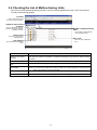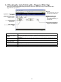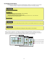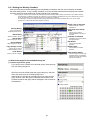
1
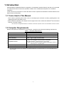
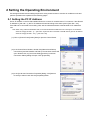
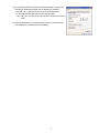
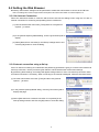
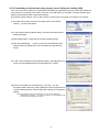
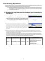
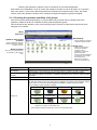
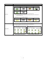
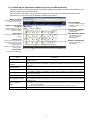
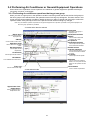
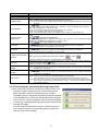
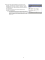
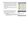
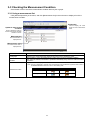
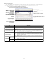
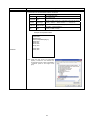
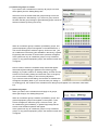
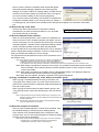
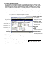
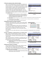
Mitsubishi Electric Air-conditioner Control System
Centralized Controller
GB-24A Web Browser Operation Manual
Contents
1 Introduction...............................................................................1
1-1 Terms Used in This Manual...............................................................1
1-2 Computer Requirements...................................................................1
2 Setting the Operating Environment..........................................2
2-1 Setting the PC IP Address................................................................2
2-2 Setting the Web Browser..................................................................4
3 Performing Operations.............................................................6
3-1 Entering the User Name and the Password, and Connecting to the
GB-24A.............................................................................................6
3-2 Performing Air Conditioner or General Equipment Operations.......10
3-3 Checking the Measurement Condition............................................14
3-4 Checking the List of Malfunctioning Units.......................................17
3-5 Checking the List of Units with a Triggered Filter Sign...................18
3-6 Setting Schedules...........................................................................19
3-7 Checking the Malfunction Log.........................................................27
3-8 Setting the Current Date and Time.................................................28
3-9 Checking the Send Mail Log...........................................................29
4 Registering a License for Optional Functions.........................30
Before using the web browser to monitor and operate the GB-24A controller, please read
this operation manual carefully to ensure correct operation.
Retain this manual for future reference.
1 Introduction
Special features of Mitsubishi Electric Corporation’s "Centralized Controller GB-24A" are that a PC connected
to a LAN can be used to monitor the operation condition of air conditioners and perform air conditioner
operations.
In this manual, the procedures to monitor the status of and to operate the centralized controller GB-24A on the
Web browser are described.
1-1 Terms Used in This Manual
- “Click” refers to positioning the mouse cursor on the object (such as button or folder), pressing down, and
releasing the left mouse button once.
- Unless otherwise specified, the example screen images used in this manual are Windows® XP and Internet
Explorer 6.0 screen images.
Note: Windows is a registered trademark or trademark of Microsoft Corporation USA in the United States and other countries.
1-2 Computer Requirements
Monitor and operate air conditioners by web browser, computer must include the following requirements.
Table 1-1 Computer Requirements
Item
CPU
Requirement
Pentium 133MHz or faster (300MHz or faster recommended)
Memory
64M Bytes or more (128M Bytes or more recommended)
Screen resolution
1024 x 768 or higher recommended
Microsoft® Internet Explorer 6.0or later
®
Compatible browser
Note: You must have a Java execution environment.
®
(Sun Microsystems Java Plug-in Ver.1.4.2 or later).
Note: You can check the Sun Microsystems Java Plug-in version in
“Java Plug-in” in a control panel.
On-board LAN port or LAN card
One connector (10BASE-T)
Other
Pointing device such as a mouse
Note: Microsoft is a registered trademark or trademark of Microsoft Corporation USA in the United States and other countries.
Sun Microsystems and Java are trademarks or registered trademarks of Sun Microsystems Inc. in the United States and/or
other countries.
1
2 Setting the Operating Environment
PC settings and web browser settings required for using a web browser to monitor air conditioner units and
perform operations are explained in the following pages.
2-1 Setting the PC IP Address
Set an IP address on the PC that enables GB-24A to connect via a web browser. For instance, if the GB-24A
IP address is [192.168.1.1], the PC IP address will need to belong to the same system [192.168.1.101].
If the GB-24A is connected to an existing LAN, ask the LAN administrator to decide what PC IP address to
use.
Note: When using a GB-24A dedicated LAN, it is recommended that the GB-24A main unit be given an IP address
within the range [192.168.1.1] — [192.168.1.40] and the PCs connected to the GB-24A be given an IP address
within the range [192.168.1.101] — [192.168.1.150]
(1) Click on [Control Panel] under [Start] to open the Control Panel.
(2) In the Control Panel window, double click [Network and Dial-up
Connections] and the Network and Dial-up Connections window will
open. Double click on [Local Area Setting] and the [Local Area
Connection Status] dialog will open. Click [Properties].
(3) In the [Local Area Connection Properties] dialog, click [Internet
Protocol] to select it and click the [Properties] button.
2
(4) In the [Internet Protocol (TCP/IP) Properties] dialog, click [Use the
following IP address] and enter the IP address (for example,
“192.168.1.101”) that you want to set in the IP address field.
You normally set [255.255.255.0] as the subnet mask.
Note: Ask your LAN administrator to provide the IP addresses and subnet
mask.
(5) Click the [OK] button to close this dialog, and then close the other
open dialogs to complete the network setting.
3
2-2 Setting the Web Browser
Necessary web browser settings must be performed to enable the web browser to connect to the GB-24A.
Note: The settings and screen images used as examples in this manual are based on Internet Explorer 6.0.
2-2-1 No Internet Connection
Follow the instructions below to make the web browser environment settings when using the PC with no
Internet connection for monitoring and operating the air conditioners.
(1) Click the web browser menu item [Tools] and then click [Internet
Options…] to select.
(2) In the [Internet Options] tabbed dialog, click the [Connections] tab to
display.
(3) Select [Never dial a connection] in the Dial-up settings section and
click the [OK] button to close the dialog.
2-2-2 Internet connection using a dial-up
If the PC used for monitoring air conditioners and performing operations is going to connect to the Internet via
a dial-up connection, use the procedure given below to set the web browser environment settings.
By performing these settings, a message will appear asking whether or not to use a dial-up connection when
an Internet connection is necessary. When connecting to the Internet is designed, follow the directions below.
(1) Click the web browser menu item [Tools] and then click [Internet
Options…] to select.
(2) In the [Internet Options] tabbed dialog, click the [Connections] tab to
display that page.
(3) Select [Dial whenever a network connection is not present] in the
Dial-up settings section and click the [OK] button to close the dialog.
4
2-2-3 Connecting to the Internet using a proxy server (Using an existing LAN)
If the PC you use for monitoring air conditioners and performing operations is going to access the Internet via
proxy server by connecting to an existing LAN such as a LAN within your company, use the procedure given
below to set the web browser environment settings.
By performing these settings, your PC will connect to a proxy server only when connecting to the Internet.
(1) Click the web browser menu item [Tools] and then click [Internet
Options…] to select that option.
(2) In the [Internet Options] tabbed dialog, click the [Connections] tab to
display that page.
(3) Select [Never dial a connection] in the Dial-up setting section.
(4) Click the [LAN Setting . . .] button in the Local Area Network (LAN)
settings section to display the Local Area Network (LAN) Settings
dialog.
(5) In the Local Area Network (LAN) Settings dialog, check [Bypass proxy
server for local addresses] and click the [Advanced...] button.
(6) Enter the IP address for the GB-24A (e.g. 192.168.1.1) in the
Exceptions field of the Proxy Setting dialog and click the [OK] button to
close the dialog and then close the other open dialogs to complete the
setting.
Note: If connecting to more than one GB-24A, you can specify multiple IP
addresses like [192.168.1.1; 192.168.1.2], however, it is also possible to use
the asterisk (*) and specify [192.168.1*].
5
3 Performing Operations
Text below explains how to connect to the GB-24A and how to monitor and adjust the operation condition of air
conditioners. Follow the directions given here when performing operations.
Note: If the GB-24A is restarted due to a power interruption etc., wait until the screen on the GB-24A main unit displays the normal
operation screen (it takes several minutes before the normal operation screen is displayed) before using a web browser to
access the GB-24A. If access is attempted while the GB-24A is still starting up, the most recent data might not be displayed
or communication errors could occur.
Note: Default IP address of GB-24A is "192.168.1.1". (Factory setting)
3-1 Entering the User Name and the Password, and Connecting to
the GB-24A
(1) Enter the web page address in the address field of the web
browser as follows:
http://[IP address of the GB-24A]/administrator.html
Press the [Enter] key on the keyboard. A screen appears for login.
Note: For example, type “http://192.168.1.1/administrator.html” if the GB-24A
IP address is [192.168.1.1].
(2) To make connection easier for the next time, click the web
browser menu item [Favorites], click [Add to Favorites], then add
the address to the Favorites folder. Once this address is added to
the Favorites folder, it is not necessary to input the address of (1).
Simply select it from the Favorites folder and the GB-24A page
will appear.
(3) Enter the user name and the password in the login screen, and click the [Login] button. The screen for
monitoring the operation condition will appear. An explanation on how to perform operations in the normal
operation screen begins from the next page.
The table below shows the web page address for public users and managers, their respective default the
user names and passwords, and accessible functions. If there are public users who will only operate the air
conditioners, provide them with the appropriate web page address and password.
User
Managers
Web page address
http:// [IP address of GB-24A]/
administrator.html
Default
user name
administrator
Default
password
admin
Accessible functions
Monitor / operation
Measurement monitor
Schedule settings (Optional function)
Malfunction log monitor
Date/time adjustment
User registration
Send mail log monitor
Optional function registration
Note: It is recommended to change the user name and password, so users other than the manager are not permitted to change the
settings.
6
Checking the Operation Condition of the Air Conditioner or the General Equipment
Given below is an explanation on how to monitor the operation condition of a list of all groups, or of groups in
block units. When a correct user name and password is entered on the password entry screen, the screen
used to monitor the operation condition of air conditioner and general equipment groups will appear.
3-1-1 Checking the operation condition of all groups
Click the menu item [Monitor/Operation], or click [Condition List] in the sub menu to display a list of the
operation condition of all the air conditioner and the general equipment groups.
This screen allows the operator to view a list of all the groups to monitor for malfunctions and prevent units
being left on by mistake.
Menu
Sub menu
Block display
Update to most recent
condition
Click to display the operation
condition of groups in block
Click to update the screen so
that the most recent operation
condition is shown.
Group icons
These icons are used to
indicate the operation
condition of an air
conditioner or a general
Equipment groups.
The group name is displayed
by pointing to the icon with
the mouse cursor.
Switch to the operation
screen by clicking the icon.
Batch operation
Click when you want to perform
an operation on all groups at
once.
Item
Block display
Update to most recent
condition
Batch operation
Group icon
Description
Switches to the screen where you can check the operation condition according to block units.
Click [Update] to ensure the displayed items reflect the most recent operation condition.
When [Auto] is selected, information is updated automatically every minute to reflect the latest
information.
Click [Batch Operation] when you want to perform an operation on all groups at once.
The operation condition is indicated by the icon that is displayed. When you point to a group
icon with the mouse cursor, the group name is displayed. To switch to the operation screen,
click on the icon. The icons used to indicate the operation condition are shown below.
(1) Air conditioner group operation condition
ON
OFF
Error
Filter sign
Interlocked
ventilator ON
Interlocked
ventilator OFF
Schedule set
Setback
Note: Other than 4-airflow icons, 2-airflow or ceiling-suspended icons are also available.
Select the icon type on Initial Setting Web.
Note: Whether to display the filter sign can be set on Initial Setting Web.
7
Item
Description
(2) Ventilator (Lossnay) group operation condition
Group icon
ON
OFF
Schedule set
Energy saving
Error
Filter sign
Note: Whether to display the filter sign can be set on Initial Setting Web.
Note: The energy saving icon is displayed while the energy-saving control is performed in a
group of ventilator units.
(3) General equipment group operation condition
ON
OFF
Error
Schedule set
Note: Other than lighting icons, pump or card key icons are also available.
Up to 8 letters are displayed under the icon.
Note: Whether to display the group names can be set on Initial Setting Web.
Note: To display all letters, move the cursor to the icon.
Group name
With the display of group names
8
Without the display of group names
3-1-2 Checking the operation condition of groups in different blocks
Click [Block] in the screen showing the list of all groups to display the operation condition of air conditioner and
general equipment groups for each block.
Use this screen if you want to check data not included in the List screen such as operation mode and set
temperature or if you want to check operation condition for each block.
Batch operation
Click when you want to perform
an operation on all groups at
once.
Overview display
Click to display the operation
condition of groups in a list
of all groups.
Update to most recent
condition
Click to update the screen so
that the most recent operation
condition is shown.
Set temperature display
The set temperature is
displayed here.
Select block
Room temperature display
Use this to select which block to
display.
The temperature of the
indoor unit’s intake is
displayed here.
Group icons
Operation mode display
These icons are used to indicate
the operation condition of an air
conditioner or a general
equipment group.
Switch to the operation screen by
clicking the icon.
The operation mode is
displayed here.
Group name
Group names are displayed.
Item
Overview display
Update to most recent
condition
Batch operation
Select block
Group icons
Operation mode display
Set temperature display
Room temperature
display
Group name
Description
Switches to the screen where you can check the operation condition of all the groups, which are
displayed in a list.
Click [Update] to ensure the displayed items reflect the most recent operation condition.
When [Auto] is selected, information is updated automatically every minute to reflect the latest
information.
Click [Batch Operation] when you want to perform an operation on all groups in the block at
once.
Use this to select which block to display and perform operations on.
The operation condition is indicated by the icon that is displayed. To switch to the operation
screen, click on the icon.
The operation mode is displayed.
The set temperature is displayed.
During setback operation, the upper limit (top row) and lower limit (bottom row) temperatures
will appear here.
The temperature of the indoor unit’s intake is displayed.
Note: Because the temperature displayed here is of the indoor unit’s intake, it could be different from the
actual room temperature.
Note: The temperature display can be set to display in either Celsius (°C) or Fahrenheit (°F).
Group names are displayed.
9
3-2 Performing Air Conditioner or General Equipment Operations
Given below is an explanation of how to perform air conditioner or general equipment operations that target
one group, one block, or all groups.
3-2-1 Performing air conditioner operations that target one group
When you click on a group icon in the operation condition monitoring screen that shows the list of all groups or
the list of groups in the selected block, the operation screen for that group will appear. The items shown in this
screen are the current operation conditions. Modify the items you want to change and click [OK] to confirm the
operation details. Click [Cancel] to return to the previous screen without making any changes.
Note: Only the ON/OFF operation is possible on the general equipment. No operation is possible on the general equipment on
which the group operation is prohibited.
・At modes other than the setback
Group name
The name of the group is
displayed here.
Block name
Interlocked ventilator
ON/OFF
The name of the block is
displayed here.
Click to switch interlocked
ventilator ON or OFF.
ON/OFF
Fan speed of
interlocked ventilator
Click to switch to ON or OFF.
Operation mode
Click to adjust the fan speed
of the interlocked ventilator.
Click to switch the operation
mode.
Prohibit remote
controller operation
Set temperature
Click to adjust the set
temperature.
Click to select the items you do
not want the remote controller
to control.
Air direction
Click to adjust the air direction.
Fan speed
Click to adjust the fan speed.
Hold button
OK button
Turns ON/OFF the hold function
Click to confirm the operation
details. You must press the OK
button for the operation to take
effect.
Filter sign
Cancel button
Click to reset the filter sign.
Click to cancel all operations.
・At the setback mode
Upper/Lower limit
temperatures
Set the upper/lower limit
temperatures here.
10
Item
ON/OFF
Description
Operation mode
Click [ON] or [OFF] to switch to ON or OFF.
Click [Cool], [Dry], [Fan], [Heat] , [Auto] or [Setback] to switch the operation mode.
If it is a ventilator group, select [Bypass], [Heat Recovery] or [Auto].
Set temperature
to adjust the set temperature.
Click
For [Cool] and [Dry], the setting range is 67 ~ 87°F/19 ~ 30°C, for [Heat] it is 63 ~83°F/17 ~
28°C, and for [Auto] it is 67 ~ 83°F/19 ~ 28°C.
Upper/Lower limit
temperatures
Air direction
Note: Some unit models do not support certain operation modes. Unsupported operation modes are not
displayed.
Note: The temperature setting range varies depending on the unit model.
Note: If it is a ventilator model, this item is not displayed.
Note: The temperature display can be set to display in either Celsius (°C) or Fahrenheit (°F).
Upper limit temperature will appear at the top, and the lower limit temperature will appear at the
bottom.
Click
to adjust the set temperature.
The upper limit temperature is settable in the range of 69 ~ 87°F/21 ~ 30°C, and the lower limit
temperature is settable in the range of 63 ~79°F/17 ~ 26°C.
Note: Temperature ranges depend on the model.
to adjust the air direction.
Click
Note: If it is a model that does not support air direction adjustment, this item is not displayed.
Note: Available functions vary depending on the unit model.
Click
Fan speed
to adjust the fan speed.
Note: If it is a model that does not support fan speed adjustment, this item is not displayed.
Note: Available functions vary depending on the unit model.
Select the items you do not want the remote controller to control. Click the word part of [ON/OFF],
Prohibit remote controller
operation
[Mode], [Set Temp] or [Filter Sign] and switch to prohibit
or enable
.
Note: For ventilator models, there are no [Mode] item or [Set Temp] item.
Filter sign
Click [Reset] to specify whether to reset the filter sign. It is set to reset when a green indicator is
displayed on the left of Reset ([ Reset]).
Note: If filter signs are not triggered in the group, then this item is not displayed.
Interlocked ventilator
ON/OFF
Click [ON] or [OFF] to switch interlocked ventilator ON or OFF.
Fan speed of interlocked
ventilator
Click
Note: For groups that are not connected to an interlocked ventilator, the items related to interlocked
ventilators are not displayed.
to adjust the fan speed of the interlocked ventilator.
Note: For groups that are not connected to an interlocked ventilator, the items related to interlocked
ventilators are not displayed.
Click [ON] or [OFF] to turn ON/OFF the hold function.
Hold function
Note: “Hold” is a function to keep the scheduled operation from taking place.
When the Hold function is turned on, the current operation status is kept until it is turned off.
Note: When this function is turned on, the following operation from the remote controller will be prohibited:
Stop, operation mode change, preset temperature change. This cannot be overridden while the
Hold function is effective.
3-2-2 Performing the operations that target one block
(1) Select the block you want to operate as an entire block from the
operation condition monitoring screen for block lists and click
[Batch Operation]. When air conditioner groups, ventilator
(LOSSNAY) groups, and general equipment groups exist together
in the selected block, a new screen will appear to select the group.
Click one of the [All air-conditioners in this block], [All LOSSNAY
in this block], or [Other Equipment] and the screen to set the batch
operation will appear.
If the block that was selected has only air conditioner groups or
only LOSSNAY groups or only general equipment groups, this
selection screen will not appear.
11
(2) After you have made the settings on the screen for batch
operation, click [OK] and the operation settings for only the
adjusted items will be sent to all the air conditioner, ventilator
(LOSSNAY) groups, or general equipment groups contained in
the selected block.
To return to the previous screen without performing any
operations, click [Cancel].
Note: When resetting the filter sign as part of a one-block batch operation, the
accumulated ON time used to trigger the filter sign will be reset in all
units belonging to the selected block, irrespective of whether or not the
filter sign was triggered. Use the reset filter sign operation in a batch
operation in a case such as when all the unit filters in the same batch are
cleaned at once.
12
3-2-3 Performing the operations that target all groups
(1) Click [Batch Operation] from the operation condition monitoring
screen that displays all groups in a list. When air conditioner
groups, ventilator (LOSSNAY) groups, and general equipment
groups exist together in the system, a new screen will appear to
select the group. Click one of the [All air-conditioners], [All
LOSSNAY], or [Other Equipment] and the screen to set the batch
operation will appear.
If the system has only air conditioner groups or only LOSSNAY
groups or only general equipment groups, this selection screen
will not appear.
(2) After you have made the settings on the screen for batch
operation, click [OK] and the operation settings for only the
adjusted items will be sent to all the air conditioner, ventilator
(LOSSNAY) groups, or general equipment groups.
To return to the previous screen without performing any
operations, click [Cancel].
Note: When resetting the filter sign as part of an all-groups batch operation,
the accumulated ON time used to trigger the filter sign will be reset in all
units, irrespective of whether or not the filter sign was triggered. Use the
reset filter sign operation in a batch operation in a case such as when all
the unit filters are cleaned at once.
13
3-3 Checking the Measurement Condition
Given below is how to check the measurement condition either by list or graph.
3-3-1 Using a measurement list
Click [Monitor/Operation] in the menu, and click [Measurement List] in the sub menu to display a list of the
measurement condition.
Trend graph
Click to display the trend
graph for each measurement
value.
Update to most recent
condition
Click to update the screen so
that the most recent operation
condition is shown.
Measured item
The measured item is
displayed here.
Measurement value
The measurement value is
displayed here.
Item
Trend graph
Update to most recent
condition
Description
Switches to the screen where the measurement value can be checked by graph.
Click [Update] to ensure the displayed items reflect the most recent operation condition.
When [Auto] is selected, information is updated automatically every minute to reflect the latest
information.
The present value is displayed.
Note: The icon is displayed in vermilion when the measured value exceeds the upper limit alarm value or
the lower limit alarm value that is set on Initial Setting Web.
Normal
Measurement value
Temperature sensor
Humidity sensor
14
Upper/lower limit alarm
3-3-2 Using a graph
Click [Trend Graph] on the measurement condition list screen, and select the measured item to be displayed.
The measured value can be checked by graph. The graph can also be downloaded as a CSV file.
Note: [Temperature], [Humidity]can be displayed in the trend graph.
(Only a AI controller’s Temperature and Humidith can be displayed.)
Overview display
Update to most recent
condition
Click to display the measurement
value as a list.
Click to update the screen so
that the most recent operation
condition is shown.
Measurement date
Select the date when the value to
be displayed is measured.
Selection of measured
item
Upper/lower limit alarm value
Select the measured item to be
displayed.
The Upper/lower limit alarm value is
displayed.
Measurement value
The measured value is
displayed as a graph.
Download
Click to download the graph
being displayed.
Item
Overview
Update to most recent
condition
Selection of measured item
Description
Switches to the screen where the measurement value can be checked as a list.
Click [Update] to ensure the displayed items reflect the most recent operation condition.
Click the [Selection of measured item], and select the measured item to be displayed from
the list.
Note: When the peak cut function is used, selecting [Peak cut control] is possible, and the electric
power and the control level can be displayed as a graph.
Select the date when the value to be displayed is measured.
Measurement date
Note: The period of time that the graph for temperature/humidity can be displayed varies depending
on the data saving interval. When the interval is 5 minutes, the graph can be displayed for 10
days, when 1 minutes, for 2 days.
Note: The graph for peak cut control can be displayed for 3 days, the previous, the current, and the
following day.
Measurement
value
The measured item is displayed as a graph.
Note: The temperature/humidity data saving interval can be set on Initial Setting Web. (Select
Temperature,
between 1 min./2 min./5 min.)
humidity
Upper/lower
Upper/lower limit alarm value that is set on Initial Setting Web is displayed.
limit
alarm When the measurement value exceeds the upper/lower limit alarm value, the area that is
value
above/below than the upper/lower limit alarm value is displayed in yellow.
15
Item
Description
Click [Download] to download the graph being displayed.
The data format of the downloaded data is as follows.
Item
First line
File type
Second line Date
Third line
Trend target
Fourth line
Measured item
Fifth line or
Data
later
Format
121: Temperature data
122: Humidity data
yyyy/mm/dd
Note: The date format set on Initial Setting Web.will be applied.
Temperature: "Address" + M-NET address + "-" + Sensor No.
Humidity: "Address" + M-NET address + "-" + Sensor No.
Temperature: "Time,Temperature(deg C)"
Humidity: "Time,Humidity(%)"
Temperature: hh:MM, Temperature
Humidity: hh:MM, Humidity
Example of temperature data
Download
121
01/04/2007
Address 50-1
Time,Temperature(deg C)
00:00,20.3
00:05,20.1
00:10,19.8
00:15,19.3
:
23:50,18.8
23:55,18.5
Note: When the data cannot be downloaded
properly, uncheck the "Use Passive FTP
(for firewall and DSL modem compatibility)
" checkbox. (Refer to the image on the
right.)
16
3-4 Checking the List of Malfunctioning Units
Click the menu item [Monitor/Operation] and then click the sub menu [Malfunction List]. A list of units that are
currently malfunctioning appears.
All reset
Click to reset errors on all
units as one batch operation.
Update to most recent
condition
Click to update the screen so
that the most recent operation
condition is shown.
Number of malfunctioning
units
The number of malfunctioning
units is displayed here.
Group name
The name of the group is
displayed here.
Error code
The error code is displayed
here.
Unit address
The unit address is displayed
here.
Item
Update to most recent
condition
Description
Click [Update] to ensure the displayed items reflect the most recent operation condition.
When [Auto] is selected, information is updated automatically every minute to reflect the latest
information.
Click [All Reset] when you want to reset the errors on all the malfunctioning units at once.
All reset
Number of malfunctioning
The number of malfunctioning units is displayed.
units
The name of the group is displayed.
Group Name
Note: If a unit, such as an outdoor unit or system controller, has not been registered in a group that is the
object of the operation, this area will be blank.
Unit address
The unit address is display
Error code
The error code of the error that is causing the malfunction is displayed.
17
3-5 Checking the List of Units with a Triggered Filter Sign
Click the menu item [Monitor/Operation] and click the sub menu [Filter Sign List]. A list of the units with a
triggered filter sign appears.
All reset
Click to reset the filter sign on all
units with triggered filter signs.
Update to most recent
condition
Number of units with
triggered filter signs
Click to update the screen so
that the most recent operation
condition is shown.
The number of units with
currently triggered filter signs is
displayed here.
Group name
The name of the group is
displayed here.
Reset units individually
Click to reset the filter sign for
the group the units belong to.
Unit address
The unit address is displayed
here.
Item
Update to most recent
condition
All reset
Description
Click [Update] to ensure the displayed items reflect the most recent operation condition.
When [Auto] is selected, information is updated automatically every minute to reflect the latest
information.
Click [All Reset] when you want to reset the filter sign on all units with a triggered filter sign at
once.
Number of units with
triggered filter signs
Group name
The group name is displayed.
Unit address
The unit address is displayed.
Reset units individually
Click [Reset] when you want to reset the filter sign for the group the units belong to.
The number of units with currently triggered filter signs is displayed.
18
3-6 Setting Schedules
When a license is registered for [Annual schedule/Weekly schedule], it is possible to use the annual
schedule and today’s schedule as well as additional functions for the weekly schedule.
Weekly schedule
(1) Frequency of operations per day
12 operations
(2) Operation items
[1] ON/OFF
[2] Operation mode([Cool], [Dry], [Fan], [Heat] , [Auto] or [Setback])
[3] Temperature setting (63 ~ 87°F/17~30°C)
Note: Settable temperature range varies according to model.
Note: The CITY MULTI model supports a temperature setting range of 53~83°F/12~28°C
when in Heat mode.
[4] Prohibit/enable remote controller operation
(3) Time setting unit
1 min
Annual schedule
Up to 50 days per year, such as public holidays and summer vacation can be scheduled as days that do not comply with
the weekly schedule.
Today’s schedule
A schedule for that day can be modified without modifying the weekly schedule or annual schedule.
When a license is registered, it is possible to set different weekly/annual/today’s schedules for each air
conditioner group. Moreover, for any weekly/annual/today’s schedule run for a particular day, the priority in
which it is run will be from the highest and the order will be [Today’s], [Annual], [Weekly].
Group 1
August, 2002
SUN
MON
TUE
WED
SUN
4
5
11
12
18
19
25
26
THU
Group 2
August,
FRI SAT2002
MON
10 1
13 4 14 515 616 717 8
4
5
20 1121 1222 1323 1424 15
11
12
27 1828 1929 2030 2131 22
25
26 27 1828 1929
25
26
6
7
Group 3
August,
2002
FRI SAT
MON
1 TUE2 WED3 THU
8
SUN
9
TUE2 WED3 THU
FRI
SAT
10 1
616 717 8
1323 1424 15
2
3
Days run by Weekly Schedule
9
10
Days run by Annual Schedule
16
17
23
24
30
31
9
2030 2131 22
27 28 29
19
Day run by Today’s Schedule
3-6-1 Setting the Weekly Schedule
Click the menu item [Schedule Settings] and click [Weekly Schedule] in the sub menu to display the Weekly
Schedule setting screen. To set a weekly schedule, you first must select what will be the target of this schedule
and then set the schedule details from Sunday right through to Saturday.
Note: When the contents of an operation are executed as part of a schedule these contents will continue to be in effect until they
are changed by a schedule or browser etc. Therefore, if you are setting a schedule that is only for a particular day, be sure
to set your schedule in a way that will not impact on the next day’s operation.
For example, if you wish to prohibit operations being performed from the remote controller after 17:00, set a Prohibit
operation for 17:00 and set an Enable operation for 23:59.
Select a day of the week
Select which day to set the
schedule for.
Setting Range
Copy (Day of the week)
/Paste
Select the range that
scheduling will be set for.
Click to copy or paste a
schedule between each day of
the week.
Block Name
Select the block to be set.
Contents of Schedule
Group Name
Operations set for the schedule
are displayed here.
Select the group to be set.
Edit button
Group Number
Click to set a schedule
operation.
Select the group to be set.
Delete button
Copy (Group) / Paste
Click to delete a schedule
operation.
Click to copy or paste a
schedule between groups.
Undo button
Save Settings button
Click to undo the changed.
Click to save the contents of the
schedule setting. The schedule
settings will not be saved unless
this button is pressed.
(1) Select the target for the schedule being set
(1-1) Select a particular group
If you wish to set a schedule for a particular group, select [Group]
from the Setting Range box.
Select the name of the block that the group belongs to, and then
select the group name in the Setting Object box.
Alternatively it is possible to just select the group name and the
group number. Once the group is selected, the contents of the
schedule saved for that group will be displayed in the Contents of
Schedule box.
20
(1-2) Select all groups in a block
If you want to set a schedule to be used by all groups in a block,
select [Block] from the Setting Range box.
Select the name of the block that the groups belong to from the
Setting Object box. Alternatively, if you click on a group number,
the block that the group belongs to gets selected (groups cannot be
selected unless they belong to a block).
When air conditioner groups, ventilator (LOSSNAY) groups, and
general equipment groups exist together in the selected block, a
new screen will appear to select the group. Click one of the [All
air-conditioners in this block], [All LOSSNAY in this block], or [Other
Equipment] and the screen to set the batch operation will appear.
If the system has only air conditioner groups or only LOSSNAY
groups or only general equipment groups, this selection screen will
not appear.
Next a screen to select the schedule setup method will appear.
Select either [New settings] or [Based on the following group
settings]. If you plan to add to an existing setting, and then choose
to base it on an existing setting and select the name of the group
you want to base the setting on and click the [OK] button.
If you chose to make a new setting, the Contents of Schedule box
will appear completely blank. If you chose to base your setting on
an existing group, the contents of the schedule set for that group will appear in the Contents of Schedule
box.
(1-3) Select all groups
When you want to set a schedule that will apply to all groups,
select [All Group] in the Setting Range box.
When air conditioner groups, ventilator (LOSSNAY) groups, and
general equipment groups exist together in the system, a new
screen will appear to select the group. Click one of the [All
air-conditioners], [All LOSSNAY], or [Other Equipment] and the
screen to set the batch operation will appear.
If the system has only air conditioner groups or only LOSSNAY
groups or only general equipment groups, this selection screen will
not appear.
21
Next a screen to select the schedule setup method will appear.
Select either [New settings] or [Based on the following group
settings]. If you plan to add to an existing setting, and then choose
to base it on an existing setting and select the name of the group
you want to base the setting on and click the [OK] button.
If you chose to make a new setting, the Contents of Schedule box
will appear completely blank. If you chose to base your setting on
an existing group, the contents of the schedule set for that group will appear in the Contents of Schedule
box.
(2) Select the day of the week
Click the day of the week listed in the Contents of Weekly
Schedule box you want to set the schedule for. You can select
from Sunday through to Saturday.
(3) Set the contents of the schedule
When one of the [Edit] buttons in the Contents of Schedule box is
clicked, a screen to set a schedule operation will appear. Use this
screen to set when to run an operation and set the type of schedule
operation (ON/OFF, operation mode, temperature setting, prohibit
remote controller operation) and then press the [OK] button.
It is also possible to set a schedule operation that is only an operation
mode or temperature setting modification. To do this, simply limit your
setting to the particular details you want to change.
The upper/lower limit temperatures must be set to operate the unit in
the Setback mode.
Note: When setting a schedule for all groups or for a block, it is possible to set
OK Button
all operation modes such as Auto mode etc, but if some targeted air
conditioner units do not have such a function, then those units will not run
in the specified mode. When setting the schedule, consider what functions are supported by the air conditioner units.
Note: When setting a schedule for all groups or for a block, it is possible to set prohibit remote controller
items individually. When allowing remote controller operation under K control, however, all items
must be set enable.
Note: When setting a schedule for ventilator units, the temperature setting is not displayed. Moreover,
the prohibit remote controller operation is simply [ON/OFF].
Note: Note: Only the ON/OFF operation is possible on the general equipment.
(4) Copy a schedule to another day of the week or to another group
Copy (Day of the week) / Paste
When copying a schedule between each day of the week, click
"Copy (Day of the week)" button. The color of the button turns to
green (which means the button is selected). Select the desired day,
and click "Paste" button.
When copying the entire week's schedule between groups, click
"Copy (Group)" button. Select the desired group, and click "Paste"
button.
Note: Copied schedule cannot be pasted to different type of equipment. For
example, schedule copied on the air conditioner cannot be pasted to the
ventilator equipment.
Note: The operation mode that can be pasted and the temperature setting
range vary depending on the unit type.
Copy (Group) / Paste
(5) Save the contents of schedule
After you have finished setting the contents of the schedule, save
the schedule setting by clicking the [Save Settings] button.
If the contents of the schedule setting have changed since the
previous save, you can click the [Undo] button to restore the setting
contents back to the saved settings.
Note: When saving a schedule setting for all groups or for a block containing
multiple groups, it can take several minutes until the setting is
complete due to the large number of units being set.
Save Settings button
22
3-6-2 Setting an Annual Schedule
Click the menu item [Schedule Settings] and click [Annual Schedule] in the sub menu to display the Annual
Schedule setting screen. You can use the annual schedule to set schedules for days such as public holidays
and summer vacation that need to be scheduled differently to the weekly schedule. For each air conditioner
group, it is possible to set 50 day-long settings up to 24 months into the future (including the current month).
Settings for days that have passed will be deleted automatically.
To set an annual schedule, first select the range and object of the schedule setting and then set the contents
of the schedule for each schedule pattern. After setting the contents of the schedule pattern (Pattern 1 – 5),
allocate the schedule pattern you wish to use for the days such as public holidays or summer vacation you are
setting the annual schedule for.
Note: When the contents of an operation are executed as part of a schedule these contents will continue to be in effect until they
are changed by a schedule or browser etc. Therefore, if you are setting a schedule that is only for a particular day, be sure
to set your schedule in a way that will not impact on the next day’s operation.
For example, if you wish to prohibit operations being performed from the remote controller after 17:00, set a Prohibit
operation for 17:00 and set an Enable operation for 23:59.
Select the schedule pattern
Select which pattern you wish to
set the schedule for.
Setting Range
Contents of Schedule
Select the range that
scheduling will be set for.
Operations set for the schedule
are displayed here.
Copy (Pattern) / Paste
Click to copy or paste a
schedule between each pattern.
Block Name
Select the block to be set.
Edit button
Click to set a schedule
operation.
Group Name
Select the group to be set.
Delete button
Group Number
Click to delete a schedule
operation.
Select the group to be set.
Calendar
Copy (Group) / Paste
Use the calendar to specify the
days that the selected schedule
pattern will be allocated for.
Click to copy or paste a
schedule between groups.
Undo button
Save Settings button
Click to undo the changed
Click to save the contents of the
schedule setting. The schedule
settings will not be saved unless
this button is pressed.
(1) Select the target for the schedule being set
Follow the procedure outlined for the weekly schedule (see 3-6-1) to select the range and object of the
schedule setting.
(2) Select the schedule pattern you want to set
In the Contents of Annual Schedule box situated at the upper right
part of the screen, choose the pattern you wish to set from Pattern
1 - 5. (If you do not need to modify any of the existing schedule
pattern settings, then skip steps (2) and (3).)
23
(3) Set the contents of the schedule setting
When one of the [Edit] buttons in the Contents of Schedule box is
clicked, a screen to set a schedule operation will appear. Use this
screen to set when to run an operation and set the type of schedule
operation (ON/OFF, operation mode, temperature setting, prohibit
remote controller operation) and then press the [OK] button.
It is also possible to set a schedule operation that is only an
operation mode or temperature setting modification. To do this,
simply limit your setting to the particular details you want to change.
The upper/lower limit temperatures must be set to operate the unit
in the Setback mode.
Note: When setting a schedule for all groups or for a block, it is possible to set
all operation modes such as Auto mode etc, but if some targeted air
conditioner units do not have such a function, then those units will not
run in the specified mode. When setting the schedule, consider what
functions are supported by the air conditioner units.
OK button
Note: When setting a schedule for all groups or for a block, it is possible to set prohibit remote controller items individually. When
allowing remote
Note: When setting a schedule for ventilator units, the temperature setting is not displayed. Moreover, the prohibit remote
controller operation is simply [ON/OFF].
Note: Only the ON/OFF operation is possible on the general equipment.
(4) Specify the day(s) for pattern allocation
Allocate the set schedule pattern for days such as public holidays
or summer vacation that has scheduling requirements different to
the weekly schedule.
To allocate a schedule pattern to a day, first click the pattern you
wish to allocate to select it and then select the day in the calendar
by clicking on the rectangle corresponding to the day. When
selected, the day will display the number of the pattern that has
been allocated.
If you wish to remove a pattern allocation from a day, select [Pattern Cancel] and then click on that day’s
rectangle.
(5) Copy a schedule to another pattern or to another group
Copy (Pattern) / Paste
When copying a schedule between each pattern, click "Copy
(Pattern)" button. The color of the button turns to green (which
means the button is selected). Select the desired pattern, and click
"Paste" button.
When copying all patterns of schedules or an allocated day of the
pattern between each group, click "Copy (Group)" button. Select
the desired group, and click "Paste" button.
Note: Copied schedule cannot be pasted to different type of equipment. For
example, schedule copied on the air conditioner cannot be pasted to the
ventilator equipment.
Note: The operation mode that can be pasted and the temperature setting
range vary depending on the unit type.
(6) Save the contents of schedule
After you finished setting the contents of the schedule, save the
schedule setting by clicking the [Save Settings] button.
If the contents of the schedule setting have changed since the
previous save, you can click the [Undo] button to restore the setting
contents back to the saved settings.
Note: When saving a schedule setting for all groups or for a block containing
multiple groups, it can take several minutes until the setting is complete
due to the large number of units being set.
24
Copy (Group) / Paste
3-6-3 Modifying Today's Schedule
Click the menu item [Schedule Settings], or click [Today’s Schedule] in the sub menu to display the Today’s
Schedule setting screen. Today’s Schedule can be used to set a valid schedule for just the current day without
modifying the weekly or annual schedule.
To set Today’s Schedule, first select the range and object of the setting and then set the contents of the
schedule.
Note: When the contents of an operation are executed as part of a schedule these contents will continue to be in effect until they
are changed by a schedule or browser etc. Therefore, if you are setting a schedule that is only for a particular day, be sure
to set your schedule in a way that will not impact on the next day’s operation.
For example, if you wish to prohibit operations being performed from the remote controller after 17:00, set a Prohibit
operation for 17:00 and set an Enable operation for 23:59.
Setting Range
Select the range that
scheduling will be set for.
Contents of Schedule
Operations set for the schedule
are displayed here.
Block Name
Select the block to be set.
Edit button
Group Name
Click to set a schedule
operation.
Select the group to be set.
Delete button
Group Number
Click to delete a schedule
operation.
Select the group to be set.
Copy (Group) / Paste
Click to copy or paste a
schedule between groups.
Save Settings button
Click to save the contents of the
schedule setting. The schedule
settings will not be saved unless
this button is pressed.
Undo button
Click to undo the changed
(1) Select the target for the schedule being set
Follow the procedure outlined for the weekly schedule (see 3-6-1) to select the range and object of the
schedule setting.
(2) Set the contents of the schedule setting
When one of the [Edit] buttons in the Contents of Schedule box is
clicked, a screen to set a schedule operation will appear. Use this
screen to set when to run an operation and set the type of schedule
operation (ON/OFF, operation mode, temperature setting, prohibit
remote controller operation) and then press the [OK] button.
It is also possible to set a schedule operation that is only an operation
mode or temperature setting modification. To do this, simply limit your
setting to the particular details you want to change.
The upper/lower limit temperatures must be set to operate the unit in
the Setback mode.
Note: When setting a schedule for all groups or for a block, it is possible to set
all operation modes such as Auto mode etc, but if some targeted air
conditioner units do not have such a function, then those units will not
run in the specified mode. When setting the schedule, consider what
functions are supported by the air conditioner units.
OK Button
Note: When setting a schedule for all groups or for a block, it is possible to set prohibit remote controller items individually. When
allowing remote
Note: When setting a schedule for ventilator units, the temperature setting is not displayed.
Moreover, the prohibit remote controller operation is simply [ON/OFF].
Note: Only the ON/OFF operation is possible on the general equipment.
25
(3) Copy a schedule to another group
When copying a schedule of the day between each group, click
"Copy (Group)". The color of the button turns to green (which
means the button is selected). Select the desired group, and click
"Paste" button.
Note: Copied schedule cannot be pasted to different type of equipment. For
example, schedule copied on the air conditioner cannot be pasted to
the ventilator equipment.
Note: The operation mode that can be pasted and the temperature setting
range vary depending on the unit type.
Copy (Group) / Paste
(4) Save the contents of schedule
After you have finished setting the contents of the schedule, save the
schedule setting by clicking the [Save Settings] button.
If the contents of the schedule setting have changed since the
previous save, you can click the [Undo] button to restore the setting
contents back to the saved settings.
Note: When saving a schedule setting for all groups or for a block containing
multiple groups, it can take several minutes until the setting is complete
due to the large number of units being set.
Save Settings button
26
3-7 Checking the Malfunction Log
Click the menu item [Malfunction Log] to display a log of unit errors (the last 64 errors). Click the sub menu
[Communication Error] to display, the M-NET communication error log.
Communication error log
Unit error log
Click to display the
communication error log.
Click to display the unit error
log.
Clear log
Error source address
Click to clear the error log.
The unit address of where the
error occurred is displayed here.
Update to most recent
condition
Error detection source
address
Click to update the screen so
that the most recent operation
condition is shown.
The unit address of where the
error was detected is displayed
here.
Error code
Occurred time
The error code of the error is
displayed here.
The date and time of error is
displayed here.
Error recovery date and
time
The date and time of the error
recovery is displayed here.
Item
Description
Unit error log
Click [Unit Error] to display the unit error log.
Communication error log
Clear log
Click [Communication Error] to display the M-NET communication error lo
Click [Update] to ensure the displayed items reflect the most recent condition.
When [Auto] is selected, information is updated automatically every minute to reflect the latest
information.
Click [Clear Log] to clear the error log that is being displayed.
Time Occurred
The date and time of when the error occurred is displayed.
Error source address
Error detection source
address
Error code
The unit address of where the error occurred is displayed.
The error code of the error is displayed.
Time Recovered
The date and time of the error recovery is displayed.
Update to most recent
condition
The unit address of where the error was detected is display
27
3-8 Setting the Current Date and Time
Click the menu item [System Settings] and the Date/Time Setting screen will appear. Enter the current date
and time and then press the [Save settings] to set it.
Current date/time
Enter the current date and time
here.
Summer time setting
Click to set the daylight saving
time.
Save settings
Refresh
Acquires the current Date and
Time from G-50A.
Click to set the current date and
time.
Item
Description
Current date/time
Enter the current date and time.
Save Settings
Click the [Save Settings] to set the current date and time.
Refresh
Acquires the current Date and Time from GB-24A.
Click and tick the "Automatically adjust clock for daylight saving changes" box to
adjust the daylight saving time automatically, and select the applicable country.
Note: If the applicable country is not in the selection bar, select "Custom Settings". Click "Custom
Settings" button that will appear on the right to set the daylight saving time.
Daylight saving
date and time
Summer time setting
Set the daylight
saving time.
Custom Setting Screen
28
3-9 Checking the Send Mail Log
Click the menu item [Maintenance] to display the log of mail sent when an error occurred and after error
recovery. In order for a mail to be sent when an error occurs, the date related to sending the mail must be to
set using Initial Setting Web.
Clear log
Click to clear the send mail log.
Error source address
The unit address of where the
error occurred is displayed here.
Update to most recent
condition
Error code
The error code is displayed
here.
Click to update the screen so
that the most recent condition is
shown.
Send mail status
This indicates whether the mail
was successfully sent by
displaying [OK] or [NG].
Send date/time
The date and time when the
mail was sent is displayed here.
Error status
This indicates whether mail was
sent when error [Occurred] or
after error [recovery].
Item
Update to most recent
condition
Clear log
Send date/time
Error source address
Description
Click [Update] to ensure the displayed items reflect the most recent condition.
When [Auto] is selected, information is updated automatically every minute to reflect the latest
information.
Click [Clear Log] to clear the send mail log.
The date and time of when the error occurred is displayed.
The unit address of where the error occurred is displayed.
Note: When an error occurs on the general equipment that is connected via DIDO controller, M-NET
address of the DIDO controller will be displayed. (Which means an error occurs on one of the
general equipment that is connected to the DIDO controller)
Error code
The error code of the error is displayed.
Error status
This indicates whether mail was sent when error occurred or after error recovery.
Send mail status
This indicates whether the mail was successfully sent by displaying [OK] or [NG].
29
4 Registering a License for Optional Functions
Given below is an explanation on how to register a license for optional functions. In the Login screen for
managers (see 3-1), click [Registration of Optional Functions] and the Registration of Optional Functions
screen will appear.
Please ask the dealer you purchased the product from for more details on the optional functions and how to
purchase a license number.
Sub menu
Click to return to the Login
Page.
Optional function
selection box
Current Status
Select the optional function you
want to register.
This indicates whether the
optional function is available for
use.
License number entry
field
Software version
Software version is displayed.
Enter the license number
required for registration.
Registration of license
button
Click to register your license.
(1) Open the Registration of Optional Function screen
Registration of Optional Functions
Enter the web page address in the web browser address field, click
the Enter key on the keyboard to display the Login screen (see
3-1).
Click on this screen’s menu item [Registration of Optional
Functions] to open the Registration of Optional Functions screen.
(2) Register an Optional Function
First select the optional function you wish to register from the
selection box in the Selecting Optional Function section. When an
optional function is selected, the Current Status section will
indicate whether it is available for use.
Next enter the license number you purchased for the optional
function in the license number entry field and click the [Registration
of license] button. Once this is done, the optional function will be
available for use.
If you were unsuccessful in registering an optional function, check that you did not enter the wrong license
number by mistake, that the correct optional function was selected from the selection box, and that the
GB-24A main unit’s date and time are set correctly.
30
Please be sure to put the contact address/telephone number on
this manual before handing it to the customer.
HEAD OFFICE: TOKYO BLDG. , 2-7-3, MARUNOUCHI, CHIYODA-KU, TOKYO 100-8310, JAPAN
WT05503X02
Printed in Japan
Recycled Paper