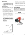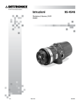
1
Instructions95-8554 IR Flame Detector X9800 11.1 Rev: 6/13 95-8554 Table of Contents Description . . . . . . . . . . . . . . . . . . . . . . . . . . . . . 1 Troubleshooting . . . . . . . . . . . . . . . . . . . . . . . 14 Outputs . . . . . . . . . . . . . . . . . . . . . . . . . . . . . . . . 1 LED . . . . . . . . . . . . . . . . . . . . . . . . . . . . . . . . . . . 2 oi (Optical Integrity) . . . . . . . . . . . . . . . . . . . . . . Maintenance . . . . . . . . . . . . . . . . . . . . . . . . . . . 14 2 Cleaning Procedure . . . . . . . . . . . . . . . . . . . . . . 15 Communication . . . . . . . . . . . . . . . . . . . . . . . . . . 3 oi Plate Removal and Replacement . . . . . . . . . 15 Data Logging . . . . . . . . . . . . . . . . . . . . . . . . . . . . 3 Periodic Checkout Procedure . . . . . . . . . . . . . . 15 Integral Wiring Compartment . . . . . . . . . . . . . . . 3 Clock Battery . . . . . . . . . . . . . . . . . . . . . . . . . . . 15 Signal Processing Options . . . . . . . . . . . . . . 3 Features . . . . . . . . . . . . . . . . . . . . . . . . . . . . . . . 16 General Application Information . . . . . . . . 4 Specifications . . . . . . . . . . . . . . . . . . . . . . . . . . 16 Response Characteristics . . . . . . . . . . . . . . . . . . 4 False Alarm Sources . . . . . . . . . . . . . . . . . . . . . . 4 Replacement Parts . . . . . . . . . . . . . . . . . . . . . 18 Factors Inhibiting Detector Response . . . . . . . . . 5 Device Repair and Return . . . . . . . . . . . . . . . 18 Important Safety Notes . . . . . . . . . . . . . . . . . 5 Ordering Information . . . . . . . . . . . . . . . . . . 18 Installation . . . . . . . . . . . . . . . . . . . . . . . . . . . . . 6 Accessories . . . . . . . . . . . . . . . . . . . . . . . . . . . . 18 Detector Positioning . . . . . . . . . . . . . . . . . . . . . . 6 X9800 Model Matrix . . . . . . . . . . . . . . . . . . . . . 19 Detector Orientation . . . . . . . . . . . . . . . . . . . . . . 6 Protection Against Moisture Damage . . . . . . . . . 7 Wiring Procedure . . . . . . . . . . . . . . . . . . . . . . . . . 7 APPENDIX A – FM APPROVAL AND PERFORMANCE REPORT . . . . . . . . . . . . . . . . . . . 20 EOL Resistors (Not Used with EQP Model) . . . . 8 Setting Device Network Addresses (EQ and EQP Models Only) . . . . . . . . . . . . 13 APPENDIX B – CSA APPROVAL . . . . . . . . . . . . . . 23 APPENDIX C – ATEX / CE APPROVAL . . . . . . . . . 24 Startup Procedure . . . . . . . . . . . . . . . . . . . . 14 Fire Alarm Test . . . . . . . . . . . . . . . . . . . . . . . . . 14 APPENDIX D – IECEx APPROVAL . . . . . . . . . . . . . 26 APPENDIX E – EN54 APPROVALS . . . . . . . . . . . . 27 APPENDIX F – ADDITIONAL APPROVALS . . . . . . 28 INSTRUCTIONS IR Flame Detector X9800 Important Be sure to read and understand the entire instruction manual before installing or operating the flame detection system. Any deviation from the recommendations in this manual may impair system performance and compromise safety. ATTENTION The X9800 includes the Automatic oi ® (Optical Integrity) feature — a calibrated performance test that is automatically performed once per minute to verify complete detector operation capabilities. Testing with an external test lamp is not approved or required. A tri-color LED on the detector faceplate indicates normal condition and notifies personnel of fire alarm or fault conditions. Description The X9800 Single Frequency IR Flame Detector meets the most stringent requirements worldwide with advanced detection capabilities and immunity to extraneous sources, combined with a superior mechanical design. The detector is equipped with both automatic and manual oi test capability. The detector has Division and Zone explosion-proof ratings and is suitable for use in indoor and outdoor applications. Microprocessor controlled heated optics increase resistance to moisture and ice. The X9800 housing is available in copper-free aluminum or stainless steel, with NEMA/Type 4X and IP66/IP67 rating. Outputs Relays The standard output configuration includes fire, fault and auxiliary relays. Output options include: –– 0 to 20 mA output (in addition to the three relays) –– –– Pulse output for compatibility with existing Detector Electronics Corporation (Det-Tronics®) controller based systems (with fire and fault relays) Eagle Quantum Premier® (EQP) compatible model –– HART communication 11.1 The standard detector is furnished with fire, fault and auxiliary relays. All three relays are rated 5 amperes at 30 Vdc. The Fire Alarm relay has redundant terminals and normally open / normally closed contacts, normally de-energized operation, and latching or non-latching operation. (no analog or relay outputs) ©Detector Electronics Corporation 2013 The Fault relay has redundant terminals and normally open contacts, normally energized operation, and latching or non-latching operation. 1 Rev: 6/13 95-8554 The Auxiliary relay has normally open / normally closed contacts, and is configurable for energized or de-energized operation, and latching or non-latching operation. LED A tri-color LED on the detector faceplate indicates normal condition and notifies personnel of fire alarm or fault conditions. Table 2 indicates the condition of the LED for each status. 0 to 20 mA Output A 0 to 20 mA output is available as an option (in addition to the three relays). This option provides a 0 to 20 mA dc current output for transmitting detector status information to other devices. The circuit can be wired in either an isolated or non-isolated configuration and can drive a maximum loop resistance of 500 ohms from 18 to 19.9 Vdc and 600 ohms from 20 to 30 Vdc. Table 1 indicates the detector status conditions represented by the various current levels. The output is calibrated at the factory, with no need for field calibration. A model with relays and 0-20 mA with HART is also available. Refer to Addendum number 95-8637 for complete details. Table 2—Detector Status Indicator Power Fault 2 mA oi Fault 4 mA Normal Operation 16 mA Pre-Alarm 20 mA Fire Alarm Green, flashing on for 0.5 sec. every 5 sec. Low IR Sensitivity Medium IR Sensitivity High IR Sensitivity Very High IR Sensitivity Quick Fire/TDSA IR Signal TDSA only IR Signal Yellow Red, flashing on for 0.5 sec. and off for 0.5 sec. Steady Red One Green Flash Two Green Flashes Three Green Flashes Four Green Flashes One Yellow Flash Two Yellow Flashes oi (Optical Integrity) Automatic oi The X9800 includes the Automatic oi feature — a calibrated performance test that is automatically performed once per minute to verify complete detector operation capabilities. No testing with an external test lamp is required. The detector automatically performs the same test that a maintenance person with a test lamp would perform — once every minute, 60 times per hour. However, a successful Automatic oi test does not produce an alarm condition. The X9800 signals a fault condition when less than half of the detection range remains. This is indicated by the Fault output and is evident by the yellow color of the LED on the face of the detector. See the "Troubleshooting" section for further information. LON/SLC Output The EQP model is designed for use exclusively with Det-Tronics' Eagle Quantum Premier system. The detector communicates with the system controller over a digital communication network or LON/SLC (Local Operating Network / Signaling Line Circuit). The LON/ SLC is a fault tolerant, two wire digital communication network arranged in a loop configuration. Analog and relay outputs are not available on this model. 11.1 Power On/Normal Man oi On Power-Up, The LED Flashes in Sequence as Follows, Indicating Sensitivity and Signal Processing Status Detector Status General Fault Green Fire (Alarm) Table 1—Detector Status Conditions Indicated by Current Level 1 mA Power On/Normal Auto oi (no fault or fire alarm) Pre-Alarm/Background IR An alarm condition will normally over-ride a fault condition, unless the nature of the fault condition impairs the ability of the detector to generate or maintain an alarm output, i.e. loss of operating power. 0 mA LED Indicator Fault NOTE The output of the 0 to 20 mA current loop is not monitored by the fault detection circuitry of the X9800. Therefore, an open circuit on the loop will not cause the fault relay to change state or the detector status LED to indicate a fault. The status of the LED always follows the status of the relays. Current Level (±0.3 mA) Detector Status Magnetic oi / Manual oi The detector also incorporates both Magnetic oi (Mag oi) and Manual oi (Man oi) features that provide the same calibrated test as the Automatic oi, and in addition actuates the Alarm output to verify operation for preventive maintenance requirements. These features can be performed at any time and eliminate the need for testing with a non-calibrated external test lamp. 2 95-8554 Integral Wiring Compartment CAUTION These tests require disabling of all extinguishing devices to avoid release resulting from a successful test. All external wiring to the device is connected within the integral junction box. The detector is furnished with four conduit entries, with either 3/4 inch NPT or M25 threads. The Mag oi test is performed by placing a magnet at the location marked "MAG OI" on the outside of the detector (see Figure 2). The Man oi test is accomplished by connecting the oi lead (terminal 22) to power supply minus via an external switch. The magnet or switch must be held in place for a minimum of 6 seconds to complete the test. Either of these test methods activates the calibrated IR emitter. If the resulting signal meets the test criteria, indicating that greater than half of the detection range remains, the Alarm output changes state, the indicating LED changes to red, and the 0-20 mA current output goes to 20 mA. This condition remains until the magnet is removed or the switch is released, regardless of whether the relays are set for latching or non-latching operation. Signal Processing Options The X9800 features signal processing options. These options determine the type of logic that the detector will use for processing fire signals to customize the X9800 to the application. Two signal processing options are available for the X9800: TDSA enabled –– Both TDSA and Quick Fire enabled (either initiates fire alarm). Time Domain Signal Analysis (TDSA) The TDSA signal processing technique analyzes the input signal in real time, requiring the IR signal to flicker randomly in order to recognize it as a fire condition. If less than half of the detection range remains, no alarm is produced and a fault is generated. The fault indication can be reset by momentarily applying the Mag oi or Man oi switch. Using TDSA signal processing, the X9800 ignores regularly chopped blackbody sources (occurring in areas where moving conveyors and hot objects in proximity to one another result in a regularly chopped IR signal), because it looks for a less uniform signal. However, in the presence of a regularly chopped signal, the detector is more susceptible to false alarms due to sporadic IR that functions as a trigger when occurring in conjunction with the regularly chopped signal. NOTE Refer to Appendix A for FM verification of Det-Tronics’ o i function. Communication The X9800 is furnished with an RS-485 interface for communicating status and other information with external devices. The RS-485 supports MODBUS protocol, with the detector configured as a slave device. Quick Fire (High Speed) For HART communication, connect a HART communicator across a 250 ohm resistor in the 0-20 mA loop. The Quick Fire (High Speed) feature can be used in conjunction with the TDSA signal processing method. This method overrides TDSA requirements in the event of a sudden and intense signal, such as the result of a flash fire. When Quick Fire is activated, the detector is capable of responding to an intense fire signal in less than 30 milliseconds (0.030 seconds). Using the Quick Fire feature in conjunction with TDSA signal processing allows the detector to provide a high speed response to a large, non-flickering fire (such as in high pressure gas applications). Additionally, when the Quick Fire feature and TDSA signal processing are used in conjuction, the detector maintains an ability to respond to fires that start very small and grow in size and intensity over time. NOTE The EQP model uses LON/SLC communication. RS-485 and HART communication are not available on the EQP model. Data Logging Data logging capability is also provided. Status conditions such as normal, power down, general and oi faults, pre-alarm, fire alarm, time and temperature are recorded. Each event is time and date stamped, along with the temperature and input voltage. Event data is stored in non-volatile memory when the event becomes active, and again when the status changes. Data is accessible using Det-Tronics' Inspector Connector accessory, RS-485, or the EQP Controller. 11.1 –– 3 95-8554 General Application Information EMI/RFI Interference The X9800 is resistant to interference by EMI and RFI, and is EMC Directive compliant and CE marked. It will not respond to a 5 watt walkie-talkie at distances greater than 1 foot (0.3 m). Response Characteristics Response is dependent on the detector's sensitivity setting, distance, type of fuel, temperature of the fuel, and time required for the fire to come to equilibrium. As with all fire tests, results must be interpreted according to an individual application. Non-Carbon Fires The response of the X9800 is limited to carbonaceous fuels. It should not be used to detect fires from fuels that do not contain carbon, such as hydrogen, sulfur and burning metals. See Appendix A for third-party approved fire test results. Additional fire test results are available from Det-Tronics. Welding FALSE ALARM SOURCES It is recommended that the system be bypassed during welding operations in situations where the possibility of a false alarm cannot be tolerated. Gas welding mandates system bypass, since the gas torch is an actual fire. Arc welding rods can contain organic binder materials in the flux that burn during the welding operation and are detectable by the X9800. Welding rods with clay binders do not burn and will not be detected by the X9800. However, system bypass is always recommended, since the material being welded may be contaminated with organic substances (paint, oil, etc.) that will burn and possibly cause the X9800 to alarm. The detector has been designed to ignore steady state infrared sources that do not have a flicker frequency characteristic of a fire, however, it should be noted that if these steady state infrared sources are hot enough to emit adequate amounts of infrared radiation in the response range of the IR sensor and if this radiation becomes interrupted from the view of the detector in a pattern characteristic of a flickering flame, the IR sensor can respond. Any object having a temperature greater than 0° Kelvin (–273°C) emits infrared radiation. The hotter the object, the greater the intensity of the emitted radiation. The closer the infrared source is to the detector, the greater the potential for a false alarm. The IR sensor can respond to IR radiation sources that can meet the amplitude and flicker requirements of the detector such as vibrating hot objects. Artificial Lighting The X9800 should not be located within 3 feet (0.9 m) of artificial lights. Excess heating of the detector could occur due to heat radiating from the lights. 11.1 4 95-8554 Important Safety Notes Factors Inhibiting Detector Response Windows Warning Do not open the detector assembly in a hazardous area when power is applied. The detector contains limited serviceable components and should never be opened. Doing so could disturb critical optical alignment and calibration parameters, possibly causing serious damage. Glass and Plexiglas windows significantly attenuate radiation and must not be located between the detector and a potential flame source. If the window cannot be eliminated or the detector location changed, contact Det-Tronics for recommendations regarding window materials that will not attenuate radiation. Obstructions Caution The wiring procedures in this manual are intended to ensure proper functioning of the device under normal conditions. However, because of the many variations in wiring codes and regulations, total compliance to these ordinances cannot be guaranteed. Be certain that all wiring complies with the NEC as well as all local ordinances. If in doubt, consult the authority having jurisdiction before wiring the system. Installation must be done by a properly trained person. Radiation must be able to reach the detector in order for it to respond. Care must be taken to keep physical obstructions out of the line of view of the detector. Smoke Smoke will absorb radiation. If accumulations of dense smoke can be expected to precede the presence of a flame, then detectors that are used in enclosed areas should be mounted on the wall approximately 3 feet (0.9 m) from the ceiling where the accumulation of smoke is reduced. Caution To prevent unwanted actuation or alarm, extinguishing devices must be disabled prior to performing detection system tests or maintenance. Detector Viewing Windows It is important to keep the detector viewing windows as free of contaminants as possible in order to maintain maximum sensitivity. Commonly encountered substances that can significantly attenuate IR radiation include, but are certainly not limited to, the following: –– Dust and dirt buildup –– Paint overspray –– Water and ice Caution The IR flame detectors are to be installed in places where the risk of mechanical damage is low. Attention Remove the protective cap from the front of the detector before activating the system. Attention Observe precautions for handling electrostatic sensitive devices. 11.1 5 95-8554 Installation note The recommended lubricant for threads and O‑rings is a silicone free grease (p/n 005003001) available from Detector Electronics. Under no circumstances should a lubricant containing silicone be used. • Dense fog, rain as well as certain gases and vapors can absorb IR radiation and reduce the sensitivity of the detector. • If possible, fire tests can be conducted to verify correct detector positioning and coverage. • For ATEX installations, the X9800 Flame Detector housing must be electrically connected to earth ground. Detector Positioning Detectors should be positioned to provide the best unobstructed view of the area to be protected. The following factors should also be taken into consideration: • Identify all high risk fire ignition sources. • Be sure that enough detectors are used to adequately cover the hazardous area. • Be sure that the unit is easily accessible for cleaning and other periodic servicing. • Verify that all detectors in the system are properly located and positioned so that any fire hazards are within both the Field of View (FOV) and detection range of the detector. Det-Tronics' Q1201C Laser Aimer is recommended for establishing the detector's FOV. Refer to Appendix A for specific information regarding detector range and FOV. • The detector should be aimed downward at least 10 to 20 degrees to allow lens openings to drain (see Figure 1). The detector should be positioned so that its FOV does not cover areas outside the hazardous area. This will minimize the possibility of false alarms caused by activities outside the area requiring protection. • Detector Orientation Refer to Figure 2 and ensure that the oi plate will be oriented as shown when the X9800 is mounted and sighted. This will ensure proper operation of the oi system and will also minimize the accumulation of moisture and contaminants between the oi plate and the viewing windows. IMPORTANT If removed, the o i plate must be securely tightened to ensure proper operation of the oi system (40 oz./inches [28.2 N . cm] recommended). oi PLATE PLACE MAGNET HERE TO INITIATE MAGNETIC oi The detector must be mounted on a rigid surface in a low vibration area. IR VIEWING WINDOW oi MAGNET B2174 DETECTOR STATUS INDICATOR Figure 2—Front View of the X9800 CENTER AXIS OF DETECTOR FIELD OF VIEW INCORRECT CENTER AXIS OF DETECTOR FIELD OF VIEW CORRECT D1974 NOTE: DETECTOR MUST ALWAYS BE AIMED DOWNWARD AT LEAST 10 TO 20 DEGREES. Figure 1—Detector Orientation Relative to Horizon 11.1 6 95-8554 Protection Against Moisture Damage note R e f e r t o “ Po w e r C o n s u m p t i o n” i n t h e “Specifications” section of this manual. It is important to take proper precautions during installation to ensure that moisture will not come in contact with the electrical connections or components of the system. The integrity of the system regarding moisture protection must be maintained for proper operation and is the responsibility of the installer. The use of shielded cable is required to protect against interference caused by EMI and RFI. When using cables with shields, terminate the shields as shown in Figures 7 through 12, and Figure 15. Consult the factory if not using shielded cable. If conduit is used, we recommend installing drains, according to local codes, at water collection points to automatically drain accumulated moisture. It is also recommended to install at least one breather, according to local codes, at upper locations to provide ventilation and allow water vapor to escape. In applications where the wiring cable is installed in conduit, the conduit must not be used for wiring to other electrical equipment. If disconnection of power is required, separate disconnect capability must be provided. Conduit raceways should be inclined so that water will flow to low points for drainage and will not collect inside enclosures or on conduit seals. If this is not possible, install conduit drains above the seals to prevent the collection of water or install a drain loop below the detector with a conduit drain at the lowest point of the loop. CAUTION Installation of the detector and wiring should be performed only by qualified personnel. Detector Mounting Install the mounting arm assembly on a rigid surface. The ideal installation surface should be free of vibration and suitable to receive 3/8 inch (M9) bolts with a length of at least 1 inch (25 mm). The surface must also have sufficient capacity to hold the detector and mounting arm weights (See "Specifications" section). Refer to the Q9033 Mounting Arm manual (95-8686) for additional mounting information. See Figure 3 for dimensions. Conduit seals are not required for compliance with explosion-proof installation requirements, but are highly recommended to prevent water ingress in outdoor applications. Units with M25 threads must use an IP66/IP67 washer to prevent water ingress. Wiring Procedure Wire Size and Type The system should be wired according to local codes. The wire size selected should be based on the number of detectors connected, the supply voltage and the cable length. Typically 16 AWG or 2.5 mm2 shielded cable is recommended. Wires should be stripped 3/8 inch (9 mm). A minimum input voltage of 18 Vdc must be present at the X9800. 4X ø0.42 (1.1) 3.0 (7.6) 4.0 (10.2) 13.1 (33.4) NOTE: THIS ILLUSTRATION SHOWS THE DETECTOR MOUNTED AT THE 10° MINIMUM. THESE DIMENSIONS WILL CHANGE BASED ON THE DETECTOR’S MOUNTING ANGLE. 3.0 (7.6) 4.0 (10.2) 10.6 (27.0) E2069 Figure 3—Q9033 Mounting Arm without Collar Attachment Dimensions in Inches (cm) (See Figure 1 for Correct Detector Orientation.) 11.1 7 95-8554 Relay and 0-20 mA Output Models EOL Resistors (Not Used with EQP Model) Follow the instructions below to install the X9800. To ensure that the insulating material of the wiring terminal block will not be affected by the heat generated by EOL resistors, observe the following guidelines when installing the resistors. 1. Make field connections following local ordinances and guidelines in this manual. Refer to Figures 4 through 12. 2. Check all field wiring to be sure that the proper connections have been made. 1. Required EOL resistor power rating must be 5 watts minimum. Important Do not test any wiring connected to the detector with a meg-ohmmeter. Disconnect wiring at the detector before checking system wiring for continuity. note EOL resistors must be ceramic, wirewound type, rated 5 watts minimum, with actual power dissipation not to exceed 2.5 watts. This applies to ATEX/IEC installations only. 3. Make the final sighting adjustments and use a 14 mm hex wrench to ensure that the mounting arm assembly is tight. 2. Resistor leads should be cut to a length of approximately 1 1/2 inches (40 mm). 3. Bend the leads and install the EOL resistor as shown in Figure 6. 4. Maintain a 3/8 inch (10 mm) minimum gap between the resistor body and the terminal block or any other neighboring parts. NOTE The EOL resistor can only be used within the flameproof terminal compartment. Unused conduit entries shall be closed with suitable blanking elements. 3/8 INCH (10 MM) GAP MINIMUM Figure 4—X9800 Terminal Block 9 4-20 mA + 19 4-20 mA – 29 SPARE 8 4-20 mA + REF 18 4-20 mA – REF 28 SPARE 7 COM FIRE 17 COM FIRE 27 COM AUX 6 N.O. FIRE 16 N.O. FIRE 26 N.O. AUX 5 N.C. FIRE 15 N.C. FIRE 25 N.C. AUX 4 COM FAULT 14 COM FAULT 24 RS-485 A 3 N.O. FAULT 13 N.O. FAULT 23 RS-485 B 2 24 VDC + 12 24 VDC + 22 MAN Oi 1 24 VDC – 11 24 VDC – 21 24 VDC – 19 18 17 16 15 14 13 12 11 B2126 BULKHEAD Figure 6—EOL Resistor Installation C2061 Figure 5—Wiring Terminal Identification 11.1 8 95-8554 X9800 DETECTOR FIRE ALARM PANEL ALARM + 24 VDC – 19 4-20 mA – SPARE 29 18 4-20 mA – REF SPARE 28 COM AUX 27 N.O. AUX 26 N.C. AUX 25 9 4-20 mA + 8 4-20 mA + REF 7 COM FIRE2 COM FIRE 17 6 N.O. FIRE2 N.O. FIRE 16 5 N.C. FIRE2 4 E.O.L. DEVICE4 N.C. FIRE 15 COM FAULT1 COM FAULT 14 RS-485 A 24 3 N.O. FAULT1 N.O. FAULT 13 RS-485 B 23 2 24 VDC + 12 24 VDC + MAN Oi 22 1 24 VDC – 11 24 VDC – 24 VDC – 21 oi TEST 3 WIRING NOTES: B2176 1 IN NORMAL OPERATION WITH NO FAULTS OCCURRING, THE FAULT RELAY COIL IS ENERGIZED AND THE NORMALLY OPEN (N.O.) AND COMMON (COM) CONTACTS ARE CLOSED. 2 ALARM RELAY IS NORMALLY DE-ENERGIZED WITH NO ALARM CONDITION PRESENT. 3 INDIVIDUAL MANUAL oi TEST SWITCHES CAN BE INSTALLED REMOTELY OR A DETECTOR SELECTOR AND ACTIVATION SWITCH CAN BE INSTALLED AT THE FIRE PANEL. TEST SWITCHES ARE NOT SUPPLIED. 4 REFER TO SPECIFICATIONS SECTION FOR EOL RESISTOR VALUES. REFER TO EOL RESISTORS SECTION FOR INSTALLATION DETAILS. Figure 7—Ex d Wiring Option X9800 DETECTOR FIRE ALARM PANEL 9 4-20 mA + 19 4-20 mA – SPARE 29 8 4-20 mA + REF 18 4-20 mA – REF SPARE 28 ALARM EOL DEVICE 4 7 COM FIRE2 COM FIRE 17 COM AUX 27 ALARM 6 N.O. FIRE2 N.O. FIRE 16 N.O. AUX 26 5 N.C. FIRE2 N.C. FIRE 15 N.C. AUX 25 4 COM FAULT1 COM FAULT 14 RS-485 A 24 3 N.O. FAULT1 13 N.O. FAULT RS-485 B 23 2 24 VDC + 12 24 VDC + MAN Oi 22 1 24 VDC – 11 24 VDC – 24 VDC – 21 + 24 VDC – oi TEST 3 B2177 WIRING NOTES: 1 IN NORMAL OPERATION WITH NO FAULTS OCCURRING, THE FAULT RELAY COIL IS ENERGIZED AND THE NORMALLY OPEN (N.O.) AND COMMON (COM) CONTACTS ARE CLOSED. 2 ALARM RELAY IS NORMALLY DE-ENERGIZED WITH NO ALARM CONDITION PRESENT. 3 INDIVIDUAL MANUAL oi TEST SWITCHES CAN BE INSTALLED REMOTELY OR A DETECTOR SELECTOR AND ACTIVATION SWITCH CAN BE INSTALLED AT THE FIRE PANEL. TEST SWITCHES ARE NOT SUPPLIED. 4 EOL RESISTOR SUPPLIED BY PANEL. Figure 8—Ex e Wiring Option 11.1 9 95-8554 X9800 DETECTOR X9800 DETECTOR PLC PLC 600 Ω MAX AT 24 VDC 9 4-20 mA + 19 4-20 mA – 29 + 8 4-20 mA + REF 18 28 + – 7 17 27 – 4 TO 20 mA 24 VDC 600 Ω MAX AT 24 VDC 9 + 6 16 26 5 15 25 4 TO 20 mA 24 VDC 13 3 2 24 14 4 – 24 VDC + 12 24 VDC – 11 MAN Oi – 28 17 27 6 16 26 5 15 25 4 14 24 2 24 VDC + 12 1 24 VDC – 11 23 13 MAN Oi 22 C2179 24 VDC – 21 24 VDC – 21 Oi TEST1 24 VDC + – Figure 10—X9800 Detector Wired for Non-Isolated 0 to 20 mA Current Output (Sinking) 24 VDC + – X9800 DETECTOR PLC 9 4-20 mA + 19 4-20 mA – 29 X9800 DETECTOR 19 4-20 mA – 29 + 8 18 28 + 8 18 28 – 7 17 27 – 7 17 27 6 16 26 6 16 26 5 15 25 5 15 25 4 14 24 4 14 24 4 TO 20 mA 24 VDC 18 4-20 mA – REF 7 3 Figure 9—X9800 Detector Wired for Non-Isolated 0 to 20 mA Current Output (Sourcing) 600 Ω MAX AT 24 VDC 8 22 Oi TEST1 PLC 29 23 C2178 1 + 19 4-20 mA – 4-20 mA + + – 9 600 Ω MAX AT 24 VDC 4 TO 20 mA 24 VDC + – 23 3 2 24 VDC + 12 MAN Oi 22 2 1 24 VDC – 11 24 VDC – 21 13 3 C2180 4-20 mA + 13 23 24 VDC + 12 MAN Oi 22 24 VDC – 11 24 VDC – 21 C2181 1 Oi TEST1 Oi TEST1 Figure 12—X9800 Detector Wired for Isolated 0 to 20 mA Current Output (Sinking) Figure 11—X9800 Detector Wired for Isolated 0 to 20 mA Current Output (Sourcing) NOTES: 1. INDIVIDUAL MANUAL oi TEST SWITCHES CAN BE INSTALLED REMOTELY OR A DETECTOR SELECTOR AND ACTIVATION SWITCH CAN BE INSTALLED AT THE FIRE PANEL. TEST SWITCHES ARE NOT SUPPLIED. 11.1 10 95-8554 5. Check all field wiring to be sure that the proper connections have been made. EQP Model 1. Connect external wires to the appropriate terminals inside the device junction box, shown in Figure 13. See Figure 14 for terminal identification. 6. Replace the device cover and apply input power. 2. Connect the shield of the power cable to “earth ground” at the power source. 7. Make the final sighting adjustments and use a 14 mm hex wrench to ensure that the mounting arm assembly is tight. 3. Connect shields for the LON cable as indicated. See Figure 15. NOTE Refer to the Eagle Quantum Premier system manual (95-8533) for information regarding power requirements, network communication cable requirements, and configuration. NOTE DO NOT ground any shields at the detector housing. 4. With input power disconnected, set the device network address. (See “Setting Device Network Addresses” section of this manual for switch setting procedure.) Figure 13—X9800 Terminal Block (EQP Model) 6 COM SHIELD 16 COM SHIELD 5 COM 1 A 15 COM 2 A 4 COM 1 B 14 COM 2 B 3 POWER SHIELD 13 POWER SHIELD 2 24 VDC + 12 24 VDC + 1 24 VDC – 11 24 VDC – B2089 Figure 14—Wiring Terminal Identification for X9800 EQP Model 11.1 11 95-8554 11.1 C 45 12 9 3+ RELAY 5 RELAY 6 RELAY 7 C 42 NO 43 NC 44 31 NO 32 NC NC 41 29 NC RELAY 3 30 C C 39 NO 40 28 NO NC 38 26 NC RELAY 2 27 C C 36 NO 37 25 NO NC 35 23 NC RELAY 1 24 C NO 34 22 NO P5 C 33 DIGITAL INPUTS 21 C C COMMON C B IN–/OUT+ B A + SUPPLY A C COMMON C B IN–/OUT+ B A + SUPPLY A C COMMON C B IN–/OUT+ B A + SUPPLY A C COMMON C B IN–/OUT+ B A + SUPPLY A P3 1 2 CH 3 P4 8– 20 8+ 19 CH 7 12 4– 11 4+ 7– 18 7+ 17 A 4 P4 B 5 3 COM1 SHIELD 6 COM2 1 4 P2 2 24 VDC – 24 VDC + 5 3 SHIELD 6 P1 EQP3700DCIO CH 2 10 3– 6– 16 6+ 15 5– 14 5+ 13 P3 A 56 B 55 CH 6 8 2– 7 2+ 6 1– 5 1+ P2 59 TxD 58 RxD 57 GND GND 54 P8 NC 47 FAULT NO 46 CH 5 DB-9 CONNECTION TO COM PORT OF PC TXD 3 RXD 2 GND 5 50 A 53 P9 49 B 52 P6 48 COM1 SHIELD 51 COM2 1 3 P7 2 24 VDC – 24 VDC + 4 P1 CONTROLLER CH 1 CH 4 CH 8 RELAY 4 RELAY 8 95-8554 – – 24 VDC BATTERY + H N AC LINE 24 VDC SUPPLY + + + – – POWER – – + DISTRIBUTION + + – + – + – 2 B N H AC LINE COM2 15 14 16 A B 5 4 6 COM1 SHIELD Figure 15—A Typical EQP System 4 3 1 2 C A 10 3 P3 B 11 1 BUS BAR SHIELD 12 COM1 12 24 VDC + 2 8 5 COM2 11 24 VDC – 1 7 24 VDC – 24 VDC + 3 6 SHIELD EQPX9800 13 SHIELD 4 9 EQP2100PSM COM2 15 14 16 A B SHIELD 5 4 6 COM1 2 15 14 16 COM2 A B SHIELD 5 4 6 COM1 12 24 VDC + 2 3 11 24 VDC – 1 SHIELD EQPX9800 13 12 24 VDC + 3 11 24 VDC – 1 SHIELD EQPX9800 13 3 B A 14 15 5 4 6 COM1 SHIELD 16 COM2 12 24 VDC + 2 11 24 VDC – 1 SHIELD EQPX9800 13 A2210 ADDRESS SWITCHES SENSOR MODULE REMOVED FROM HOUSING A2191 Figure 16—Location of Address Switches The address number is binary encoded with each switch having a specific binary value with switch 1 being the LSB (Least Significant Bit), see Figure 17. The device’s LON address is equal to the added value of all closed rocker switches. All “Open” switches are ignored. Setting Device Network Addresses (EQ and EQP Models Only) Overview of Network Addresses Each device on the LON must be assigned a unique address. Addresses 1 to 4 are reserved for the controller. Valid addresses for field devices are from 5 to 250. Example: for node No. 5, close rocker switches 1 and 3 (binary values 1 + 4); for node No. 25, close rocker switches 1, 4 and 5 (binary values 1 + 8 + 16). IMPORTANT If the address is set to zero or an address above 250, the switch setting will be ignored. Note The field device sets the LON address only when power is applied to the device. Therefore, it is important to set the switches before applying power. If an address is ever changed, system power must be cycled before the new address will take effect. Duplicated addresses are not automatically detected. Modules given the same address will use the number given and report to the controller using that address. The status word will show the latest update, which could be from any of the reporting modules using that address. After setting address switches, record the address number and device type. Setting Field Device Addresses Selection of the node address is done by setting rocker switches on an 8 switch “DIP Switch Assembly” within the detector’s housing. Refer to Figure 16 for switch location. WARNING The network address switches are located within the detector housing. Disassembly of the detector head that contains powered electrical circuits is required to gain access to the network address switches. For hazardous areas, the area must be de-classified before attempting disassembly of the device. Always observe precautions for handling electrostatic sensitive devices. ON BINARY VALUE 1 2 3 4 5 1 2 4 8 16 32 64 128 6 7 8 NODE ADDRESS EQUALS THE ADDED VALUE OF ALL CLOSED ROCKER SWITCHES OPEN = OFF CLOSED = ON A2190 Figure 17—Address Switches for X9800 11.1 13 95-8554 Startup Procedure Table 3—Current Level Output Troubleshooting Guide When installation of the equipment is complete, perform the “Fire Alarm Test” below. Fire Alarm Test 1. Disable any extinguishing connected to the system. equipment that is 2. Apply input power to the system. 3. Initiate an oi test. (See “Magnetic oi / Manual oi” under Optical Integrity in the Description section of this manual. Current Level (±0.3 mA) Status Action 0 mA Power Fault Check system wiring. 1 mA General Fault Cycle power.1 2 mA oi Fault Clean windows.2 4 mA Normal Operation 16 mA Hi Background IR Fault 20 mA Fire Alarm Remove IR source or aim detector away from IR source. 1If fault continues, return device to factory for repair. 2See “Maintenance” section for cleaning procedure. 4. Repeat this test for all detectors in the system. If a unit fails the test, refer to the “Troubleshooting” section. 5. Verify that all detectors in the system are properly aimed at the area to be protected. (Det-Tronics' Q1201C Laser Aimer is recommended for this purpose.) 5. Turn off the input power to the detector and check all wiring for continuity. Important: Disconnect wiring at the detector before checking system wiring for continuity. 6. Enable extinguishing equipment when the test is complete. 6. If all wiring checks out and cleaning of the oi plate/ window did not correct the fault condition, check for high levels of background IR radiation by covering the detector with the factory supplied cover or aluminum foil. If the fault condition clears, extreme background IR radiation is present. Re-adjust the view of the detector away from the IR source or relocate the detector. Troubleshooting Warning The sensor module (“front” half of the detector) contains no user serviceable components and should never be opened. The terminal compartment is the only part of the enclosure that should be opened by the user in the field. 1. Disable any extinguishing connected to the unit. equipment that If none of these actions corrects the problem, return the detector to the factory for repair. NOTE It is highly recommended that a complete spare be kept on hand for field replacement to ensure continuous protection. is 2. Inspect the viewing windows for contamination and clean as necessary. (Refer to the “Maintenance” section for complete information regarding cleaning of the detector viewing windows.) Maintenance 3. Check input power to the unit. IMPORTANT Pe r i o d i c fl a m e p a t h i n s p e c t i o n s a re n o t recommended, since the product is not intended to be serviced and provides proper ingress protection to eliminate potential deterioration of the flamepaths. 4. If the fire system has a logging function, check the fire panel log for output status information. See Table 3 for information regarding 0 to 20 mA output. Warning The sensor module (“front” half of the detector) contains no user serviceable components and should never be opened. The terminal compartment is the only part of the enclosure that should be opened by the user in the field. 11.1 14 95-8554 NOTE Refer to the X9800 Safety manual (95-8672) for specific requirements and recommendations applicable to the proper installation, operation, and maintenance of all SIL-Certified X9800 Flame Detectors. LOOSEN TWO CAPTIVE SCREWS To maintain maximum sensitivity and false alarm resistance, the viewing windows of the X9800 must be kept relatively clean. Refer to the following procedure for cleaning instructions. GRASP VISOR AND REMOVE oi PLATE Cleaning Procedure B2175 CAUTION Disable any extinguishing equipment that is connected to the unit to prevent unwanted actuation. Figure 18—oi Plate Removal To clean the windows and oi plate, use Det-Tronics' window cleaner (p/n 001680-001) and a soft cloth, cotton swab or tissue and refer to the following procedure: 4. Recalibrate the detector's oi system. Refer to the Inspector Monitor manual (95-8581) for instructions regarding oi plate replacement and oi system recalibration. 1. Disable any extinguishing equipment that is connected to the unit. Caution Do not replace the oi reflector plate without also recalibrating the oi system. NOTE Remove input power when cleaning the detector windows. The rubbing motion on the surface of the windows during cleaning can create static electricity that could result in unwanted output activation. Recalibration of the oi system requires the use of the Inspector Connector Cable and Inspector Monitor Software. These two items are included in the oi replacement kit, or they can be purchased separately. See Ordering Information for details. 2. Clean the viewing window and reflective surfaces of the oi plate using a clean cloth, cotton swab or tissue, and Det-Tronics' window cleaning solution. Use Isopropyl alcohol for contaminations that the Det-Tronics window cleaning solution can not remove. If a fault condition is still indicated after cleaning, remove and clean the oi plate using the oi Plate Removal and Replacement procedure. Periodic Checkout Procedure In compliance with SIL 2, a checkout of the system using the Mag oi or Man oi feature should performed regularly to ensure that the system is operating properly. Refer to Table 1 in the X9800 Safety manual (95-8672) for frequency of proof tests. To test the system, perform the “Fire Alarm Test” as described in the “Startup Procedure” section of this manual. Important When used in extreme environments, the reflective surface of the detector oi plate may eventually deteriorate, resulting in reoccurring oi faults and the need for oi plate replacement. Clock Battery The real time clock has a backup battery that will operate the clock with no external power. Return the device to the factory for battery replacement if needed. oi Plate Removal and Replacement 1. Disable any extinguishing equipment that is connected to the unit. NOTE If the backup battery is depleted, there is no effect on the operation of the flame detector, but the time stamping of the data log may be affected. 2. Loosen the two captive screws, then grasp the oi plate by the visor and remove it from the detector. See Figure 18. 3. Install the new (or cleaned) oi plate. 11.1 15 95-8554 Features Specifications • Responds to a fire in the presence of modulated blackbody radiation (i.e. heaters, ovens, turbines) without false alarm. OPERATING VOLTAGE— 24 Vdc nominal (18 Vdc minimum, 30 Vdc maximum). Maximum ripple is 2 volts peak-to-peak. • High speed capability — 30 milliseconds. • Built-in data logging / event monitoring, up to 1500 events (up to 1000 general, 500 alarms). • Microprocessor controlled heated optics increased resistance to moisture and ice. • Automatic, manual or magnetic oi testing. • Easily replaceable oi plate. • Fire, fault and auxiliary relays standard. • 0 to 20 mA isolated output (optional). POWER CONSUMPTION— Without heater:2.1 watts at 24 Vdc nominal; 3.5 watts at 24 Vdc in alarm. 2.2 watts at 30 Vdc nominal; 4.0 watts at 30 Vdc in alarm. Heater only: 8 watts maximum. Total power: 16.5 watts at 30 Vdc with EOL resistor installed and heater on maximum. EOL resistor must be ceramic, wirewound type, rated 5 watts minimum, with actual power dissipation not to exceed 2.5 watts. • Eagle Quantum Premier LON/SLC output (optional). For HART model, refer to Addendum number 95-8637. • HART communication (optional) • A tri-color LED on the detector faceplate indicates normal condition and notifies personnel of fire alarm or fault conditions. • Operates under adverse weather conditions. • Mounting arm allows easy sighting. • Integral wiring compartment for ease of installation. • Explosion-proof/flame-proof detector housing. Meets FM, CSA, ATEX and CE certification requirements. • Class A wiring per NFPA-72. • Meets NFPA-33 response requirement for under 0.5 second (available when model selected). • 3 year warranty. • Advanced signal processing (TDSA). • RFI and EMC Directive compliant. for POWER UP TIME— Fault indication clears after 0.5 second; device is ready to indicate an alarm condition after 30 seconds. OUTPUT RELAYS— Fire Alarm relay, Form C, 5 amperes at 30 Vdc: The Fire Alarm relay has redundant terminals and normally open / normally closed contacts, normally de-energized operation, and latching or non-latching operation. Fault Alarm relay, Form A, 5 amperes at 30 Vdc: The Fault relay has redundant terminals and normally open contacts, normally energized operation, and latching or non-latching operation. Auxiliary relay, Form C, 5 amperes at 30 Vdc: The auxiliary relay has normally open / normally closed contacts, normally energized or de-energized operation, and latching or nonlatching operation. Associated Manuals CURRENT OUTPUT (Optional)— 0 to 20 milliampere (±0.3 mA) dc current, with a maximum loop resistance of 500 ohms from 18 to 19.9 Vdc and 600 ohms from 20 to 30 Vdc. List of X9800 related manuals: TITLE Pulse EQP SIL 2 (Safety) HART Addendum FORM NUMBER 95-8555 95-8533 95-8672 95-8637 Q9033 Mounting Arm and Collar Attachment 95-8686 Inspector Monitor Software for X-Series Flame Detectors 95-8581 11.1 LON Output— Digital communication, transformer isolated (78.5 kbps). TEMPERATURE RANGE— Operating: –40°F to +167°F (–40°C to +75°C). Storage: –67°F to +185°F (–55°C to +85°C). Hazardous location ratings from –55°C to +75°C available on flameproof model. HUMIDITY RANGE— 0 to 95% relative humidity, can withstand 100% condensing humidity for short periods of time. 16 95-8554 WIRING— Field wiring screw terminals are UL/CSA rated for up to 14 AWG wire, and are DIN/VDE rated for 2.5 mm2 wire. Screw terminal required torque range is 3.5–4.4 in.-lbs. (0.4-0.5 N·m). 100% REPRESENTS THE MAXIMUM DETECTION DISTANCE FOR A GIVEN FIRE. THE SENSITIVITY INCREASES AS THE ANGLE OF INCIDENCE DECREASES. VIEWING ANGLE 15° 30° 0° 100 ft (30.5 m) 15° Important: 18 Vdc minimum must be available at the detector. For ambient temperatures below –10°C (14°F) and above +60°C (140°F) use field wiring suitable for both minimum and maximum ambient temperature. 30° 90 ft (27.4 m) 80 ft (24.4 m) 45° 45° 70 ft (21.3 m) 60 ft (18.3 m) DETECTION DISTANCE (PERCENT) Thread SIZE— Conduit connection: Four entries, 3/4 inch NPT or M25. Conduit seal not required. 50 ft (15.2 m) 40 ft (12.2 m) 30 ft 9.1 m) SHIPPING WEIGHT (Approximate)— Aluminum: 7 pounds (3.2 kilograms). Stainless Steel: 14.6 pounds (6.7 kilograms). Mounting Arm (AL): 6 pounds (2.75 kilograms). Mounting Arm (SS): 14 pounds (6.4 kilograms). 20 ft (6.1 m) 10 ft (3 m) B1288 Figure 19—Detector Cone of Vision WARRANTY PERIOD— 3 years. CONE OF VISION— The detector has a 90° cone of vision (horizontal) with the highest sensitivity lying along the central axis. See Figure 19. CERTIFICATION— FM ® APPROVED RESPONSE TIME— 32 inch methane plume: < 10 seconds. 1 foot x 1 foot n-Heptane: < 15 seconds. (See Appendix A for details.) VdS For complete approval details, refer to the appropriate Appendix: ENCLOSURE MATERIAL— Copper-free aluminum (painted) or Stainless Steel (316/ CF8M Cast). Appendix A - FM Appendix B - CSA Appendix C - ATEX/CE Appendix D - IECEx Appendix E - EN54 Appendix F - Additional approvals Vibration— Conformance per FM 3260: 2000, MIL-STD 810C (Curve AW). DIMENSIONS— See Figure 20. 4.7 (11.9) B2223 10.2 (25.9) 4.8 (12.2) Figure 20—Dimensions in Inches (cm) 11.1 17 95-8554 Replacement Parts Ordering Information The detector is not designed to be repaired in the field. If a problem should develop, refer to the Troubleshooting section. If it is determined that the problem is caused by an electronic defect, the device must be returned to the factory for repair. When ordering, please specify: X9800 IR Flame Detector Refer to the X9800 Model Matrix below for details Q9033 Mounting Arm is required: –– Q9033A for aluminum detectors only –– Q9033B for aluminum and stainless steel detectors Replacement Parts Part Number Description 009208-002 oi Replacement kit for X52/X22/X98 (5 Reflector Plates) with Inspector Connector and Monitor Replacement oi Reflector Plate for X52/X22/X98 (requires Inspector Connector to calibrate) 007307-002 Accessories NOTE: Refer to Instruction Manual 95-8530 to determine the correct oi Replacement Plate. Part Number Description 000511-029 103881-001 Converter RS485 to RS232 Converter RS485 to USB W6300B1002 Serial Inspector Connector (Inspector Monitor software included) W6300B1003 USB Inspector Connector (Inspector Monitor software included) Flame Inspector Monitor CD Model 475 HART Communicator Magnet Magnet and Adapter for Extension Pole Magnet and Extension Pole Q1116A1001, Air Shield (AL) Q1118A1001 Aluminum Air Shield/Flange Mount (AL) Q1118S1001 Stainless Steel Air Shield/Flange Mount (SS) Q1120A1001 Paint Shield mounting ring (AL) Q1198A1001 Dual Air Shield/Flange Mount (X9800 only)/(AL) Q1201 Laser Laser Battery, 3V Lithium (laser) Q1201C1001 X-Series Laser Holder (AL/Plastic) Q2000A1001 X-Series Weather Shield (AL) Q9033B Stainless Steel Mounting Arm Assembly is for aluminum and stainless steel detectors Q9033A Aluminum Mounting Arm Assembly is for aluminum detectors only Q9033 Collar Attachment Stop Plug, 3/4” NPT, AL Stop Plug, 3/4” NPT, SS Stop Plug, M25, AL, IP66 Stop Plug, M25, SS, IP66 Stop Plug, 20 Pack, 3/4”NPT, AL Stop Plug, 20 Pack, 3/4”NPT, SS Stop Plug, 20 Pack, M25, AL, IP66 Stop Plug, 20 Pack, M25, SS, IP66 14 mm Hex Wrench (Steel) Screwdriver O-ring - Rear Cover (Viton) 1 oz grease for detectors (non-silicon) Window cleaner (6 pack) 007819-001 007819-002 009207-001 103922-001 102740-002 008082-001 007739-001 007240-001 007818-001 007818-002 009177-001 009199-001 006097-001 102871-001 007255-001 007338-001 Device Repair and Return Prior to returning devices, contact the nearest local Detector Electronics office so that a Return Material Identification (RMI) number can be assigned. A written statement describing the malfunction must accompany the returned device or component to assist and expedite finding the root cause of the failure. 007290-001 Pack the unit properly. Always use sufficient packing material. Where applicable, use an antistatic bag as protection from electrostatic discharge. 007290-002 011385-001 101197-001 101197-004 101197-005 101197-003 010816-001 010817-001 010818-001 010819-001 103363-001 103406-001 107427-040 005003-001 001680-001 note Det-Tronics reserves the right to apply a service charge for repairing returned product damaged as a result of improper packaging. Return all equipment transportation prepaid to the factory in Minneapolis. NOTE It is highly recommended that a complete spare be kept on hand for field replacement to ensure continuous protection. 11.1 18 95-8554 X9800 Model Matrix MODEL DESCRIPTION X9800 Single Frequency IR Flame Detector TYPE MATERIAL A Aluminum S Stainless Steel (316) TYPE THREAD TYPE 4M 4 PORT, METRIC M25 4N 4 PORT, 3/4" NPT TYPE OUTPUTS 11 Relay 13 Relay and 4-20 mA 14 Eagle Quantum Premier (EQP) 15 Relay and Pulse 16 Addressable Module Only (Third Party Type)* 23 HART, Relay and 4-20 mA TYPE APPROVALS** R VNIIPO/VNIIFTRI (Russia) T SIL/FM/CSA/ATEX/CE/IECEx W FM/CSA/ATEX/CE/IECEx TYPE CLASSIFICATION 1 Division/Zone Ex d e 2 Division/Zone Ex d *The Addressable Module Only (Type 16) is not FM approved. **Type Approvals can use one or more letters to designate the approvals of the product. 11.1 19 95-8554 APPENDIX A FM Approval and Performance Report THE FOLLOWING ITEMS, FUNCTIONS AND OPTIONS DESCRIBE THE FM APPROVAL: • Explosion-proof for Class I, Div. 1, Groups B, C and D (T5) Hazardous (Classified) Locations per FM 3615. • Dust-ignition proof for Class II/III, Div. 1, Groups E, F and G (T5) Hazardous (Classified) Locations per FM 3615. • Nonincendive for Class I, Div. 2, Groups A, B, C and D (T3) Hazardous (Classified) Locations per FM 3611. • Nonincendive for Class II, Div. 2, Groups F and G (T3) Hazardous (Classified) Locations per FM 3611. • Enclosure rating NEMA/Type 4X per NEMA 250. • Ambient Temperature Limits:–40°F to +167°F (–40°C to +75°C). • Automatic Fire Alarm Signaling Performance verified per FM 3260 (2000). Flameproof per ANSI/ISA 60079-0, -1, -7 for Class I, Zone 1 AEx d e IIC Gb; T6 (Tamb –40°C to +60°C); T5 (Tamb –40°C to +75°C) AEx d IIC Gb; T6 (Tamb –40°C to +60°C); T5 (Tamb –40°C to +75°C) for Zone 21 AEx tb T80°C Tamb –40°C to +75°C Degree of protection provided by Enclosure IP66/67, Hazardous Locations for use in the U.S. The following accessories are FM approved for use with the X9800 Flame Detector: Part Number Description 102740-002 007739-001 007290-001 007290-002 011385-001 Magnet Magnet and Extension Pole Q9033B Stainless Steel Mounting Arm Assembly is for aluminum and stainless steel detectors Q9033A Aluminum Mounting Arm Assembly is for aluminum detectors only Q9033 Collar Attachment The following performance criteria were verified: AUTOMATIC OPTICAL INTEGRITY TEST: The detector generated an optical fault in the presence of contamination on any single or combination of lens surfaces resulting in a loss of approximately 50% of its detection range, verifying that the detector performs a calibrated Automatic oi test for each sensor. Upon removal of the contamination, the detector fault was cleared and the detector was verified to detect a fire. MANUAL OPTICAL INTEGRITY TEST: The Manual / Magnetic oi performs the same calibrated test as the Automatic oi, and additionally actuates the alarm relay to verify output operation. If there is a 50% loss of its detection range, an alarm signal is not generated. The oi test procedure, as described in the "Magnetic oi / Manual oi" section of this instruction manual, is the approved external optical test method for this detector to verify end-to-end detector function. This test replaces the function and need of a traditional external test lamp. 11.1 20 95-8554 FM Approval and Performance Report – Continued RESPONSE CHARACTERISTICS Very High Sensitivity Fuel Size / Flow Rate Distance feet (m) Typical Response Time (seconds)* TDSA Quick Fire n-Heptane 1 x 1 foot 85 (25.9) 15 On Off Methane 32 inch plume 60 (18.3) 5 On Off Propane Torch 2 (0.6) 0.04 On On *Add 2 seconds for EQP model. High Sensitivity Fuel Size / Flow Rate Distance feet (m) Typical Response Time (seconds)* TDSA Quick Fire n-Heptane 1 x 1 foot 50 (15.2) 8 On Off Methane 32 inch plume 35 (10.7) 3 On Off Pyrodex 40 grams 10 (3) 0.1 On On Black Powder 40 grams 10 (3) 0.04 On On n-Heptane 1 x 1 foot 50 (15.2) 6 On On *Add 2 seconds for EQP model. Low Sensitivity Fuel Size / Flow Rate Distance feet (m) Typical Response Time (seconds)* TDSA Quick Fire n-Heptane 1 x 1 foot 15 (4.6) 8 On Off *Add 2 seconds for EQP model. RESPONSE CHARACTERISTICS IN THE PRESENCE OF FALSE ALARM SOURCES High Sensitivity, TDSA On, Quick Fire Off Distance feet (m) Fire Source Distance feet (m) Typical Response Time (seconds)* Sunlight, direct, modulated/unmodulated — 2 inch dia Heptane 10 (3) < 30 Sunlight, reflected, modulated/unmodulated — 2 inch dia Heptane 10 (3) < 30 70 w sodium vapor lamp, unmodulated 5 (1.5) 2 inch dia Heptane 5 (1.5) 3 70 w sodium vapor lamp, modulated 5 (1.5) 2 inch dia Heptane 5 (1.5) 3 250 w mercury vapor lamp, unmodulated 5 (1.5) 2 inch dia Heptane 5 (1.5) 2 250 w mercury vapor lamp, modulated 5 (1.5) 2 inch dia Heptane 5 (1.5) 3 300 w incandescent lamp, unmodulated 5 (1.5) 2 inch dia Heptane 5 (1.5) 3 300 w incandescent lamp, modulated 5 (1.5) 2 inch dia Heptane 5 (1.5) 3 500 w shielded quartz halogen lamp, unmodulated 5 (1.5) 2 inch dia Heptane 5 (1.5) 2 500 w shielded quartz halogen lamp, modulated 5 (1.5) 2 inch dia Heptane 5 (1.5) 2 1500 w electric radiant heater, unmodulated 10 (3) 2 inch dia Heptane 5 (1.5) 3 1500 w electric radiant heater, modulated 10 (3) 2 inch dia Heptane 3 (0.9) 13 Two 34 w fluorescent lamps, unmodulated 3 (0.9) 2 inch dia Heptane 10 (3) 3 Two 34 w fluorescent lamps, modulated 3 (0.9) 2 inch dia Heptane 10 (3) 5 Arc welding 15 (4.6) 2 inch dia Heptane 5 (1.5) N/A False Alarm Souce *Add 2 seconds for EQP model. 11.1 21 95-8554 FM Approval and Performance Report – Continued FALSE ALARM IMMUNITY High Sensitivity, TDSA On, Quick Fire Off False Alarm Souce Distance feet (m) Modulated Response Unmodulated Response — No alarm No alarm Sunlight, direct, reflected NA No alarm No alarm Arc welding 15 (4.6) No alarm No alarm 70 w sodium vapor lamp 3 (0.9) No alarm No alarm 250 w mercury vapor lamp 3 (0.9) No alarm No alarm 300 w incandescent lamp 3 (0.9) No alarm No alarm 500 w shielded quartz halogen lamp 3 (0.9) No alarm No alarm 1500 w electric radiant heater 10 (3) No alarm No alarm Two 34 w fluorescent lamps 3 (0.9) No alarm No alarm Vibration FIELD of view Very High Sensitivity, Quick Fire Off Fuel Size Distance feet (m) Horizontal (degrees) Typical Horiz. Response Time (seconds)* Vertical (degrees) Typical Vert. Response Time (seconds)* n-Heptane 1 x 1 foot 42.5 (13) +45 –45 12 14 +45 –30 10 16 Methane 32 inch plume 30 (9.1) +45 –45 7 4 +45 –30 6 4 *Add 2 seconds for EQP model. High Sensitivity, TDSA On, Quick Fire Off Fuel Size Distance feet (m) Horizontal (degrees) Typical Horiz. Response Time (seconds)* Vertical (degrees) Typical Vert. Response Time (seconds)* n-Heptane 1 x 1 foot 25 (7.6) +45 –45 7 7 +45 –30 6 5 Methane 32 inch plume 17.5 (5.3) +45 –45 6 3 +45 –30 4 4 *Add 2 seconds for EQP model. High Sensitivity, TDSA On, Quick Fire On Fuel Size Distance feet (m) Horizontal (degrees) Typical Horiz. Response Time (seconds)* Vertical (degrees) Typical Vert. Response Time (seconds)* Black Powder 40 Grams 5 (1.5) +45 –45 0.04 0.03 +45 –30 0.04 0.04 *Add 2 seconds for EQP model. 11.1 22 95-8554 APPENDIX B CSA Approval PRODUCTS CLASS 4818 04 - SIGNAL APPLIANCES - Systems - For Hazardous Locations Class I, Division 1, Groups B, C, and D (T5); Class II, Division 1, Groups E, F, and G (T5); Class I, Division 2, Groups A, B, C, and D (T3); Class II, Division 2, Groups F and G (T3); Class III; Enclosure NEMA/Type 4X; Infrared Flame Detector/Controller X9800 series, rated 18-30 Vdc, 2.1 Watts to 16.5 Watts. Relay contacts rated 5 Amps @ 30 Vdc. APPLICABLE REQUIREMENTS CSA Std C22.2 No. 25-1966 – Enclosures for use in Class II Groups E, F & G Hazardous Locations. CSA Std C22.2 No. 30-M1986 – Explosion-Proof Enclosures for use in Class I Hazardous Locations. CAN/CSA C22.2 No. 94-M91 – Special Purpose Enclosures. CSA Std C22.2 No. 142-M1987 – Process Control Equipment. CSA Std C22.2 No. 213-M1987 – Nonincendive Electrical Equipment for use in Class I, Division 2 Hazardous Locations. The following accessories are CSA approved for use with the X9800 Flame Detector: Part Number Description 102740-002 007739-001 007290-001 007290-002 011385-001 Magnet Magnet and Extension Pole Q9033B Stainless Steel Mounting Arm Assembly is for aluminum and stainless steel detectors Q9033A Aluminum Mounting Arm Assembly is for aluminum detectors only Q9033 Collar Attachment 11.1 23 95-8554 APPENDIX C ATEX / CE Approval EC-TYPE EXAMINATION CERTIFICATE DEMKO 02 ATEX 132195X Increased Safety Model FM APPROVED Flameproof Model II 2 G II 2 G FM 0539 II 2 D II 2 D Ex d e IIC T6–T5 Gb Ex d IIC T6–T5 Gb Ex tb IIIC T80°C Ex tb IIIC T80°C T6 (Tamb = –50°C to +60°C) T6 (Tamb = –55°C to +60°C) T5 (Tamb = –50°C to +75°C) T5 (Tamb = –55°C to +75°C) IP66/IP67.IP66/IP67. 0539 ® ® APPROVED Compliance with: EN 60079-0: 2009 EN 60079-1: 2007 EN 60079-7: 2007 EN 60079-31: 2009 EN / IEC 60529: 2001. Installation instructions The field wiring connections in the terminal compartment are ATEX certified and accepts wiring specifications from 14-24 AWG or 2.5-0.2 mm2. The flame detector model X9800IR shall be installed according to the instructions given by the manufacturer. The cable entry devices shall be certified in type of explosion protection flameproof enclosure "d" for use with the terminal compartment in type of explosion protection flameproof enclosure "d", or in type of explosion protection increased safety "e" for use with the terminal compartment in type of explosion protection increased safety "e". They shall be IP66/IP67 rated, suitable for the conditions of use and correctly installed. Unused entries shall be closed with suitable certified blanking elements. The metal housing for the Infrared (IR) flame detector type X9800 must be electrically connected to earth ground. For ambient temperatures below –10°C and above +60°C use field wiring suitable for both minimum and maximum ambient temperature. Special conditions for safe use: The EOL resistor can only be used within the flameproof terminal compartment. EOL resistors must be ceramic, wirewound type, rated 5 watts minimum, with actual power dissipation not to exceed 2.5 watts. The Infrared (IR) flame detector type X9800 is to be installed in places where there is a low risk of mechanical damage. 11.1 24 95-8554 NOTE Operational performance verified from –40°C to +75°C. note An optional third party addressable module can only be used within the Ex d flameproof model unless the addressable module is component certified as Ex e for use within the Ex d e increased safety model. NOTE Refer to “EOL Resistors” section for installation details. All cable entry devices and blanking elements shall be certified to “E-generation” or “ATEX” standards, in type of explosion protection increased safety “e” or flameproof enclosure “d” (as applicable), suitable for the conditions of use and correctly installed. They shall maintain the degree of ingress protection IP66/IP67 for the apparatus. Unused conduit entries shall be closed with suitable blanking elements. Note For ATEX installations, the X9800 detector housing must be electrically connected to earth ground. The following accessories are ATEX approved for use with the X9800 Flame Detector: Part Number Description 007290-001 007290-002 011385-001 Q9033B Stainless Steel Mounting Arm Assembly is for aluminum and stainless steel detectors Q9033A Aluminum Mounting Arm Assembly is for aluminum detectors only Q9033 Collar Attachment 11.1 25 95-8554 APPENDIX D IECEx Approval IECEx Certificate of Conformity DEMKO IECEx ULD 06.0018X Ex d e IIC T6-T5 Gb Ex d IIC T6-T5 Gb Ex tb IIIC T80°C Ex tb IIIC T80°C T6 (Tamb = –50°C to +60°C) or T6 (Tamb = –55°C to +60°C) T5 (Tamb = –50°C to +75°C) T5 (Tamb = –55°C to +75°C) IP66/IP67.IP66/IP67. Compliance with: IEC 60079-0: 2007, Ed. 5 IEC 60079-1: 2007, Ed. 6 IEC 60079-7: 2006, Ed. 4 IEC 60079-31: 2008, Ed. 1 EN / IEC 60529: 2001. Installation instructions The field wiring connections in the terminal compartment are suitable certified and accepts wiring specifications from 14-24 AWG or 2.5-0.2 mm2. The flame detector model X9800IR shall be installed according to the instructions given by the manufacturer. The cable entry devices shall be certified in type of explosion protection flameproof enclosure "d" for use with the terminal compartment in type of explosion protection flameproof enclosure "d", or in type of explosion protection increased safety "e" for use with the terminal compartment in type of explosion protection increased safety "e". They shall be IP66/IP67 rated, suitable for the conditions of use and correctly installed. Unused entries shall be closed with suitable certified blanking elements. The metal housing for the Infrared (IR) flame detector type X9800 must be electrically connected to earth ground. For ambient temperatures below –10°C and above +60°C use field wiring suitable for both minimum and maximum ambient temperature. Special conditions for safe use: The EOL resistor can only be used within the flameproof terminal compartment. EOL resistors must be ceramic, wirewound type, rated 5 watts minimum, with actual power dissipation not to exceed 2.5 watts. The Infrared (IR) flame detector type X9800 is to be installed in places where there is a low risk of mechanical damage. The following accessories are IECEx approved for use with the X9800 Flame Detector: Part Number Description 007290-001 007290-002 011385-001 Q9033B Stainless Steel Mounting Arm Assembly is for aluminum and stainless steel detectors Q9033A Aluminum Mounting Arm Assembly is for aluminum detectors only Q9033 Collar Attachment 11.1 26 95-8554 APPENDIX E EN54 ApprovalS Conventional Output AGENCY VdS – Construction Product Directive Certificate/Approval Number Basis of Approval Basis of Approval 0786 – CPD – 20779 EN 54-10 + A1 — — G 203084 VdS 2344 VdS 2504 EN 54-10 + A1 — — S 212002* VdS 2344 EN 54-13 S 212002* VdS 2344 EN 54-13 — — 0832 – CPD – 1377 EN 54-10 + A1 EN 54-17 973e/01 EN 54-10 + A1 973a/01 EN 54-10 + A1 EN 54-17 VdS BRE – EC – Certificate of Conformity LPCB LON Output Certificate/Approval Number * Approved for use in conjunction with the EN54-13 compliant EQP System. Instructions for the application of the approval component/system The installation shall take into account, that the orientation arrow on the flame detector is directed upwards, as the view angle in this direction is <90°. The IR-flame detector corresponds to class 1. The following accessories are EN54-10 and EN54-17 approved for use with the X9800 Flame Detector: Part Number Description 102740-002 007739-001 007290-001 007290-002 011385-001 Magnet Magnet and Extension Pole Q9033B Stainless Steel Mounting Arm Assembly is for aluminum and stainless steel detectors Q9033A Aluminum Mounting Arm Assembly is for aluminum detectors only Q9033 Collar Attachment 11.1 27 95-8554 APPENDIX F ADDITIONAL APPROVALS SIL 2 IEC 61508 Certified SIL 2 Capable. Applies to specific models – refer to the SIL 2 Certified X9800 Safety Manual (95-8672) for details. RUSSIA VNIIFTRI CERTIFICATE OF CONFORMITY GOST R 51330.X-99 2ExdeIICT6/T5 IP66 T6 (Tamb = –55°C to +60°C) T5 (Tamb = –55°C to +75°C). – OR – 1ExdIICT6/T5 IP66 T6 (Tamb = –55°C to +60°C) T5 (Tamb = –55°C to +75°C) VNIIPO CERTIFICATE OF CONFORMITY TO TECHNICAL REGULATIONS, GOST R 53325-2009 11.1 28 95-8554 95-8554 Detector Electronics Corporation 6901 West 110th Street Minneapolis, MN 55438 USA X3301 Multispectrum IR Flame Detector PointWatch Eclipse® IR Combustible Gas Detector FlexVu® Universal Display w/ GT3000 Toxic Gas Detector Eagle Quantum Premier® Safety System T: 952.941.5665 or 800.765.3473 F: 952.829.8750 W: http://www.det-tronics.com E: [email protected] Det-Tronics and oi (Optical Integrity) are registered trademarks or trademarks of Detector Electronics Corporation in the United States, other countries, or both. Other company, product, or service names may be trademarks or service marks of others. © Copyright Detector Electronics Corporation 2013. All rights reserved