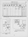
1
^
rcaVictor
TELEVISION RECEIVER
MODEL
Chassis No.
KCS
721TS
26-1 (60 cycles) KCS 26-2 (50 cycles)
Mfr. No. 274
,
Service
—
Data
1947 No. T4
RADIO CORPORATION OF AMERICA
RCA VICTOR DIVISION
CAMDEN, N.)., U.S.A.
Model 7 2 ITS
Walnut or Mahogany
GENERAL DESCRIPTION
Model 721TS
is
a twenty-one tube, direct-viewing, table-model
Television Receiver having a 10" picture tube (kinescope). The
receiver
is
complete
seven front-panel
in
one
controls.
unit
and
Features
is
operated by the use
of
the
receiver
ELECTRICAL
PICTURE
r
of
include:
Full
thirteen
picture
channel coverage; f-m sound system: improved
two stages of video amplification; A-F-C
brilliance:
improved sync ampliand separator; and reduced-hazard high-voltage supply.
horizontal hold, stabilized vertical hold;
fier
AND MECHANICAL SPECIFICATIONS
ELECTRICAL
72 ITS
AND MECHANICAL SPECIFICATIONS
PICTURE INTERMEDIATE FREQUENCIES
(Continued)
Horizontal (Picture Horizontal Hold)
-i
.Dual Control Knobs
'
Picture
Carrier
Accompanying
Frequency
25.75
Sound
21.25
Traps
Mc
Mc
Vertical
Picture
(Picture
Vertical
Hold)
J
(Contrast)
..Dual Control
Knobs
Brightness (Brilliance)
SOUND INTERMEDIATE FREQUENCIES
NON-OPERATING CONTROLS
Sound Carrier Frequency
21.25
Sound Discriminator Band Width (between peaks)
Mc
350 Kc
VIDEO RESPONSE
To
3
Mc
Horizontal
Centering
rear
Width
SWEEP DEFLECTION
Magnetic
Horizontal Linearity
Vertical
HORIZONTAL SCANNING FREQUENCY
15,750
cps
and
i-f
ad-
chassis
adjustment
rear chassis screwdriver adjustment
Height
525 line
r-f
rear chassis adjustment
Vertical Centering
Magnetic
Interlaced,
including
justments)
FOCUS
SCANNING
(not
J
rear
top
rear
Linearity
chassis
adjustment
screwdriver adjustment
chassis
chassis
adjustment
rear chassis screwdriver adjustment
Horizontal Drive
Horizontal Frequency (Fine)
rear chassis screwdriver
adjustment
VERTICAL SCANNING FREQUENCY
60 cps
FRAME FREQUENCY
30 cps
(Picture
Repetition Rate)
Horizontal Oscillator Frequency (coarse)
bottom chassis
screwdriver adjustment
Horizontal Locking Range. ...rear chassis screwdriver adjustment
OPERATING CONTROLS
Station Selector
Fine Tuning
(front
panel)
Focus
)
L
^^
i
.
i
Ion
J
Sound Volume and On-Off
S'witch
Single
Control
Knob
rear
Focus Coil
t^
t^
i_
Control Knobs
Dual
top chassis
Trup Magnet
top
chassis
chassis
wing
adjustment
screw^ adjustment
thumb screw adjustment
wing nut adjustment
top chassis
Deflection Coil
HIGH VOLTAGE WARNING
OPERATION OF THIS RECEIVER OUTSIDE THE CABINET OR WITH THE
COVERS REMOVED INVOLVES A SHOCK HAZARD FROM THE RECEIVER
POWER SUPPLIES. WORK ON THE RECEIVER SHOULD NOT BE ATTEMPTED
BY ANYONE WHO IS NOT THOROUGHLY FAMILIAR WITH THE PRECAUTIONS NECESSARY WHEN WORKING ON HIGH- VOLTAGE EQUIPMENT. DO
NOT OPERATE THE RECEIVER WITH THE HIGH-VOLTAGE COMPARTMENT
SHIELD REMOVED.
KINESCOPE HANDLING PRECAUTIONS
DO NOT OPEN THE KINESCOPE SHIPPING CARTON, INSTALL, REMOVE, OR
HANDLE THE KINESCOPE IN ANY MANNER UNLESS SHATTERPROOF
GOGGLES AND HEAVY GLOVES ARE WORN. PEOPLE NOT SO EQUIPPED
SHOULD BE KEPT AWAY WHILE HANDLING KINESCOPES. KEEP THE
KINESCOPE AWAY FROM THE BODY WHILE HANDLING.
lo its large surface area, is subjected
considerable air pressure. For these reasons, kinescopes must be handled with more care
The kinescope bulb encloses a high vacuum and, due
to
than ordinary receiving tubes.
The large end
ol the
kinescope bulb
struck, scratched, or subjected to
—particularly
the rim of the viewing surface
more than moderate pressure
at
any
time.
—must not be
In installation,
if
smoothly through the deflecting yoke, investigate and remove
force the tube. Refer to the Receiver Installation section for
trouble.
Do
not
the cause of the
detailed instructions on kinescope installation. All RCA kinescopes are shipped in special carthe tube sticks or fails to slip
tons
and should be
left
in the cartons until
carton for possible future use.
ready
for installation in the
receiver.
Keep
the
J
RECEIVER OPERATING INSTRUCTIONS
The following adjustments are necessary when turning the
receiver on ior the first time:
Turn
1.
volume
"ON"
receiver
the
control
the
SOUND
desired
channel.
advance
and
Adjust the
8.
Set
3.
Turn the PICTURE
the
to
hold control
Adjust the PICTURE control
9.
for suitable picture contrast.
necessary
some time, it may be
FINE TUNING control slightly for
improved sound fidelity.
readjust the
to
counter-
fully
one
Turn
4.
BRIGHT-
the
.^^=^
control fully coun-
then clock-
terclockwise,
a
wise
until
just
appears
station
may
it
repeat
and
the
\==J^
Turn the PICTURE
control
approximately
Adjust
6.
TUNING
sound
and
fidelity
control
for
positions
the
6
suit-
CAL
hold
control
should not
it
repeat
to
the
of
generally
is
13.
VERTI-
Adjust the
is
the
if
controls
have not been changed.
any adjustment is
If
necessary, step number
able volume.
7.
set
adjustments
the
control for best
SOUND
the
be necessary
FINE
the
6
idle period,
clockwise.
three-fourths
to
number
turned on again after an
screen.
5.
be necessary
steps
When
12.
on
another,
to
9.
glow
faint
from
In switching
11.
clockwise.
NESS
the picture
until
After the receiver has been on for
10.
STATION SELECTOR
2.
control
HORIZONTAL
appears on the screen.
approximately mid-position.
to
the
72 ITS
the
the positions of
If
PICTURE
the pattern stops vertical
essary
I
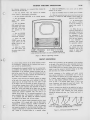
BRIGHTNESS
IN SOME RECEIVERS "BRIGHTNESS" IS
movement.
FINE TUNING
ON-OFF SOUND'
STATION SELECTOR
THE OUTER KNOB AND 'PICTURE' THE INNER
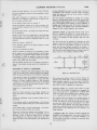
Fig/iie
I
— Receiver
have been
controls
changed,
until
sufficient.
may
it
be necsteps
to
repeat
1
through
number
9.
Operating Controls
CIRCUIT DESCRIPTION
provided
divider
new and
on the positive peaks
be described
will
briefly.
Fundamentally the horizontal
oscillator
plied to the control tube grid.
a bias
plies
A
If
and phase
to the oscillator to
tube
control
cut
on the slope
off
except
the grid
of
the two voltages are not in
relations, the control tube ap-
bring
it
into sync.
and
when
the
is
sync pulse
waveform as shown
applied
keep the
to
sufficient
is
high
is
Figure 2-A.
in
slides
the slope, the plate conduction time decreases as
down
shown
in
up the slope, then the plate
conduction time increases as shown in Figure 2-C. When the
and CI67 in its
control tube conducts capacitors C16I
Figure
2-B.
cathode
the
oscillator
and pulling
The
charge to a d-c potential proportional to the
circuit
effect
of
adjustments
effect
fine
thus
grid
into
it
LI2I
is
adjustments
is
is
of the
and hence
is
is
a
The horizontal drive
and
is
of
coefficients
oscillator
the
or
and
characteristics
control
and
circuits
case
in
should be replaced only by exact replacement.
a special
pro-
sawtooth voltage on the VI 09
of
control for picture linearity.
components
Several
have special
waveform.
part of a capacity voltage divider
vided to vary the amount
grid
waveform
lube so that conduction occurs only
resistor
capable
of
stability
of
1%
or
of
RI73
better.
a high negative coefficient resistor to compensate for
warm up drift. It is mounted within about Vi inch of the
power transformer and chassis for good heat transfer. The
R191
is
dress of this component should not be disturbed.
Strains or excessive heat should not be applied to the leads or
bodies
and
of the resistors
control
changes
page
circuits.
of resistance
associated with the horizontal oscillator
Such conditions may cause excessive
See "Critical Lead Dress" on
with age.
18.
applied as a bias
oscillator
frequency
tuned with a slug to
frequency.
in
C136C
RI56
frequency.
effect
is
VIOBA GRID CUTOFF
coarse
provided
the
is
by varying
to
horizontal
provided on the front panel to permit a
variation of frequency
CI 36 A
the
C136B
the amplitude of the
to set
phase with the sync pulses.
oscillator
in
hold control
shifting
is
control
is
of the control
the various controls associated with the circuit
are as follows.
age.
This potential
conduction time.
plate
to
the pulse slides
If
on the grid
failure,
changes phase so that the pulse
the oscillator
is
waveform and ap-
portion of the bias from the blocking oscillator
to the grid of the control tube
If
The incoming sync
circuit.
superimposed on the horizontal
the proper freguency
a free running block-
oscillator is
and discharge
ing oscillator
c
and
The general design features of the 721TS television receiver
are conventional. However, the a-f-c horizontal hold circuit is
5%
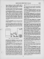
SYNC TOO EARLY
SYNC TOO LATE
NORMAL CONTROL
SHADED AREA IS PORTION OF W/AVEFORM EFFECTIVE IN PRODUCING
OSCILLATOR CONTROL VOLTAGE,
the control tube plate volt-
a variable portion
of
a
capacity
voltage
Figure 2
—Horizontal Control Waveforms
INSTALLATION INSTRUCTIONS
721TS
The Model 72 ITS television receiver is shipped complete in
one carton except for the 10BP4 kinescope. The kinescope is
shipped in a special carton and should not be unpacked until
ready ior installation.
—
are worn. People not so equipped should be kept away while
handling the kinescope. Keep the kinescope away from the
body while handling. The shipping carton should be kept for
use in case of future moves.
UNPACKING To unpack
the receiver, tear open the carton
pick the receiver up from under the bottom of the cabinet and lift it out of the shipping carton.
INSTALLATION OF KINESCOPE— The kinescope second anode
flaps,
contact is a recessed metal well in the side of the bulb. The
tube must be installed so that this contact is approximately on
grill off the back of the cabinet.
Remove the
panel from the cabinet as indicated in Figure 3.
lop.
The final orientation of the tube will be determined by
the position of the ion trap flags.
Looking at the kinescope
Take the metal
front
gun structure, it will be observed that the second cylinder from
the base inside the glass neck is provided with two small
metal flags, as shown in Figure 5. The kinescope must be
installed so that when looking down on the chassis, the two
flags will be seen as shown in Figure 4.
TO REMOVE CABINET FRONT
TAKE OUT SCREWS UNDER CABINET
LOOSEN WING NUTS INSIDE CABINET
TURN PLATES AND REMOVE FRONT
T
"S'3^
FLAGS
Figure 5
—Ion Trap
Flags
the neck of the kinescope through the
deflection and
focus coils as shown in Figure 6 until the
base of the tube
protrudes approximately two inches beyond
the focus coil.
If the tube sticks, or fails to
slip into place
Insert
smoothly, investiDo not force the
gate and remove the cause of the trouble.
tube.
Figure 3
Cabinet, Front
View
The operating control knobs are packed in a paper bag which
is tied to the focus coil mounting bracket inside the cabinet.
3-
Remove the bag.
Remove the protective cardboard shield from the 5U4G rectifier.
Make sure all tubes are in place and are firmly seated
in their sockets.
Loosen the two kinescope cushion adjustment wing screws and
Loosen the
slide the cushion toward the rear of the chassis.
deflection yoke adjustment, slide the yoke toward the rear
See Figure 4 for the location of
of the chassis and tighten.
the cushion
and yoke adjustments.
Figure 6
—Kinescope
Insertion
Early production receivers employed an
magnet
/
FLAGS
Ml
justment thumbscrews sufficiently to hold
free enough to permit adjustment.
Coil Adjustments
not in line, loosen the three focus coil adjustment wingnuts and raise, lower, or rotate the coil until alignment is obtained. Tighten the wingnuts with the coil in this
is
position.
Loosen the two lower kinescope face centering slides, and set
them at approximately mid position. See Figure 3 for location of the slides and their adjustment screws.
Loosen the
ion trap magnet adjustment thumb screws.
KINESCOPE HANDLING PRECAUTION—Do
not
open the
kine-
scope shipping carton, install, remove, or handle the kinescope
any manner, unless shatterproof goggles and heavy gloves
in
in position
but
still
the
PM
of the
From the front of the cabinet, look through the deflection yoke
and check the alignment of the focus coil with the yoke. If
the focus coil
it
type is employed, slip the assembly over the neck
kinescope with the large magnet towards the base of
the tube and with the arrow on the assembly up as shown in
Figure 4. The front magnet is movable on the assembly. The
If
— Yoke and Focus
type of ion trap
the neck of the kinescope with the coils down and the large
coil towards the base of the tube.
Tighten the magnet ad-
FRONT MACNET GAP
ON THIS SIDE AND EVEN
WITH REAR MAGNET GA»
Figure 4
EM
model 630TS receiver. Late production
receivers employed a PM type magnet as shown in Figure 4.
If an EM type of magnet is applied, slip the
assembly over
like that in the
correct position of the front magnet
side (from the rear of the cabinet)
the rear magnet.
is with the gap on the left
and even with the gap of
Connect the kinescope socket to the tube base.
Insert the
kinescope until the face of the tube protrudes approximately
one-eighth of an inch outside the front of the cabinet. Adjust
the four centering slides until the face of the kinescope is in
the center of the cabinet opening.
Tighten the four slides
securely.
Wipe the kinescope screen surface and front panel
safety glass clean of all dust and finger marks with a soft cloth
moistened with the Drackett Co.'s "Windex" or similar cleaning
agent. Install the cabinet front panel by reversal of the removing process as shown in Figure 3.
Install the control knobs
on the proper control shafts.
INSTALLATION INSTRUCTIONS
the kinescope as lar forward as possible. Slide the
kinescope cushion firmly up against the flare of the tube and
Slide the deflection
tighten the adjustment wing screws.
yoke as far forward as possible. Connect the high voltage
lead to the kinescope second anode socket.
Slip
C
The antenna and power connections should now be made.
Turn the power switch
to
control fully clockwise,
and
the "on" position, the brightness
picture control counter-clockwise.
MAGNET ADJUSTMENT—The ion trap rear magnet
poles should be placed over the ion trap flags as shown in
Figure 4.
Starting from this position adjust the magnet by
ION TRAP
moving
lorward or backward at the same time rotating
it
around the neck of the kinescope for the brightest
raster on the screen.
Reduce the brightness control setting
until the raster is slightly above average brilliance.
Adjust
the focus control (R129 on the chassis rear apron) until the
it
slightly
line structure of the raster is clearly visible.
magnet
trap
for
maximum
raster brilliance.
Readjust the ion
final touches
The
adjustment should be made with the brightness control
position with which good line focus can be
maintained.
on
this
maximum
at the
FOCUS COIL ADJUSTMENTS—Turn
and R166
to
rear apron
mid
the centering controls R152
for location of these
See Figure 7
position.
controls.
shadowed, it indicates that the
neck of the tube. Loosen the
electron beam is
focus coil adjustment wing nuts and rotate the coil about its
vertical and horizontal axes until the entire raster is visible,
approximately centered and with no shadowed corners. Tighten
the focus coil adjustment wing nuts with the coil in this
If
a corner
of
the raster
721TS
(Continued)
should show from
3'/2
to 4'/2
bars sloping
downward
to the
right.
the receiver passes the above checks and the picture is
normal and stable, the horizontal oscillator is properly aligned.
Skip "Alignment of Horizontal Oscillator" and proceed with
"Focus" adjustment.
If
ALIGNMENT OF HORIZONTAL OSCILLATOR— If
in the
above
check the receiver failed to hold sync with the hold control
at the extreme counterclockwise position or failed to hold
sync at least 60 degrees of clockwise rotation of the control
from the pull in point, it will be necessary to make the following adjustments.
—
Horizontal Frequency Adiustment Turn the horizontal hold
control to the extreme clockwise position. Tune in a television
station and adjust the rear apron horizontal frequency trimmer C136C until the picture is out of sync and shows 3Vi to
41/2 bars sloping downward to the right.
If the trimmer has
insufficient range, set the trimmer to mid-position (1 turn out
from max. capacity) and adjust the L121 horizontal frequency
adjustment until this condition is obtained. See figure 22 for
the location of L121.
—
Horizontal Locking Range Adjustment Set the horizontal
hold control to the full counter-clockwise position. Momentarily
remove the signal by switching off channel and, then back.
Slowly turn the horizontal hold control clockwise and note
the least number of diagonal bars obtained just before the
picture pulls into sync.
is
striking the
position.
c
WIDTH
a
CONTROL
more than
bars are present just before the picture pulls
range trimmer C136A
slightly clockwise.
If less than 3'/2 bars are present, adjust
C136A slightly counterclockwise. Turn the horizontal hold
control counterclockwise, momentarily remove the signal and
recheck the number of bars present at the pull in point. Repeat this procedure until 3V2 to 4'.^ bars are present.
If
4'/2
into sync, adjust the horizontal locking
Repeat the adjustments under "Horizontal Frequency Adjustment" and "Horizontal Locking Range Adjustment" until the
When the horiconditions specified under each are fulfilled.
zontal hold operates as outlined under "Check of Horizontal
Oscillator Alignment" the oscillator is properly adjusted.
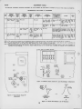
HEIGHT AND VERTICAL LINEARITY ADJUSTMENTS— Adjust
HOR.
LINEARITY
RI48
VERT.
LINEARITY
a.
FOCUS
q;^
HOR.
(OX
(CIX
*il>/VERT.
^CjpHOR.
HOR. DRIVE
CENTERING CENTERING
Figure 7
— Rear
Ct36A
LOCKING^
CI36C
«
e
HOR.FREa.''
Chassis Adjustments
the lines of the raster
are not horizontal or squared with the picture mask, rotate
the deflection yoke until this condition is obtained. Tighten
the yoke adjustment wing screw.
PICTURE ADJUSTMENTS— It
will now be necessary to obtain a
pattern picture in order to make further adjustments. See
steps 2 through 9. of the receiver operating instructions on
test
3.
Vary
the
horizontal
hold control to the extreme counter-clockwise
The picture should remain in horizontal sync. Momentarily remove the signal by switching off channel and
position.
Normally the picture will be out of sync. Turn
clockwise slowly. The number of diagonal bars
will be gradually reduced and when only 3'/2 to iVi bars
sloping downward to the left are obtained, the picture will pull
into sync upon slight additional clockwise rotation of the control.
Pull in should occur when the control is approximately
90 degrees from the extreme counterclockwise position.
The
picture should remain in sync for approximately 90 degrees
of additional clockwise rotation of the control.
At the extreme
clockwise position, the picture should be out of sync and
then back.
the control
c
to the maximum clockwise posithe horizontal drive trimmer C136B to yield the
width control LI 12
Adjust
best compromise between brightness and linearity.
the horizontal linearity control LI 13 for best linearity of the
Readjust the width control until the
right half of the picture.
Adjust horizontal centering to
picture just fills the mask.
align the picture with the mask.
FOCUS— Adjust
of the vertical
the focus control R129 for
of the test pattern.
maximum
definition
wedge
Check to see that all cushion, yoke, focus coil and ion trap
magnet thumb screws are light. Replace the cabinet back
Make sure that the back is on tight, otherwise it may
grille.
rattle
CHECK OF HORIZONTAL OSCILLATOR ALIGNMENT—Turn
AND HORIZONTAL LINEARITY ADJUSTMENTS
WIDTH. DRIVE
—Turn the
tion.
DEFLECTION YOKE ADJUSTMENT— If
page
the height control (R141 on chassis rear apron) until the picture
Adjust vertical linearity
fills the mask vertically (6% inches).
(R148 on rear apron), until the test pattern is symmetrical from
top to bottom. Adjustment of either control will require a readAdjust vertical centering to align the
justment of the other.
picture with the mask.
at
high volume.
R-F OSCILLATOR ADJUSTMENTS— With a crystal
calibrated test oscillator or heterodyne frequency meter, check
the proper
to see if the receiver r-f oscillator is adjusted to
frequency on all channels. If adjustments are required, these
should be made by the method outlined in the alignment procedure on page 10. The adjustments for channels 1 through 5
CHECK OF
and 7 through 12 are available from the front of the cabinet
by removing the station selector escutcheon as shown in Figure
Adjustments for channels 6 and 13 are under the chassis.
8.
available Television Stations, Observe the picture
proper interlacing and for the presence of
see the
interference or reflections. If these are encountered,
Tune
for
in all
detail,
section
for
on antennas on page
6.
INSTALLATION INSTRUCTIONS
72 ITS
(Continued)
The stock #226 antenna
is bi-directional on channels one
through six (44 to 88 Mc). When used on these channels, the
maximum signal is obtained when the antenna rods are broadside toward the transmitting antenna.
The stock #225 antenna with reflector is unidirectional on
channels one through six. When used on these channels, the
maximum signal is obtained when the antenna rods are broadside toward the transmitting antenna, with the antenna element between the reflector and the transmitting antenna.
When
Figure
—R-F
8
operated on channels seven through thirteen, (174 to
216 Mc), both types of antennas have side lobes. On these
channels, the maximum signal will be obtained when the
antenna is rotated approximately 35 degrees in either direction from its broadside position toward the transmitting an-
Oscillator Adjustments
tenna.
VIDEO PEAKING LINK
—A
provided to
permit changing the video response. This link is connected at
However, if transients are
the factory with the peaking in.
produced on high contrast pictures the peaking should be
taken out by removing the link on the terminal board under
the chassis near the VI 04 socket. See Figures 49 and 51 for
the connection
and
video peaking link
is
location of the link.
general, the stock #225 antenna should be
are encountered, if the signal strength is
the receiving location is noisy. If these conditions
countered, the stock #226 antenna will probably
In
flections
used if reweak, or if
are not en-
be
satisfac-
tory.
In
some
cases, the antenna should not be installed permanently
has been observed on
temporary transmission line can be
run between receiver and the antenna, allowing sufficient
slack to permit moving the antenna. Then, with a telephone
system connecting an observer at the receiver and an assistant
at the antenna, the antenna can be positioned to give the
most satisfactory results on the received signal. A shift of
direction or a few feet in antenna position may effect a treuntil the quality of the picture reception
ANTENNA TRAP—In some
a
series resonant trap across
the r-f amplifier grid circuit is provided to eliminate interference
stations on the image of channel 2, from interference
from
on channel 6 from a station on channel 10 or interference on
sets,
FM
channel 5 from a station on channel 7. In production, this
trap is adjusted to reject the channel 6-10' interference. However, in the field, it may be necessary to retouch the adjustments or to readjust the trap for channel 5-7 or FM image
a
television receiver.
mendous
A
difference in picture reception.
interference.
in the field, tune in the station on which
the interference is observed. Tune both cores of the trap for
minimum interference in the picture. See Figure 21 for the
location of the trap. Keep both cores approximately the same
by visual inspection. Then, turn one core V2 turn from the
original position and repeak the second for maximum rejecRepeat this process until the best rejection is obtained.
tion.
To adjust the trap
In severe cases of such interference,
reorient the antenna to eliminate this
it
may be
necessary
to
REFLECTIONS
—Multiple
images sometimes known as echoes
caused by the signal arriving at the antenna
by two or more routes. The second or subsequent image occurs when a signal arrives at the antenna after being reflected off a building, a hill or other object. In severe cases
of reflections, even the sound may be distorted.
In less severe
or ghosts, are
cases,
reflections
may
occur that are not noticeable as
flections but that will instead
cause a loss
re-
of definition in the
picture.
difficulty.
it may be possible to eliminate the reflections by rotating the antenna or by moving it
to a new location. In extreme cases, it may be impossible to
eliminate the reflection.
Depending upon the circumstances,
RECEIVER LOCATION—The owner should be advised
of
the importance of placing the receiver in the proper location
in the room.
The location
shjDuld
be chosen
— Away
from bright windows and so that no bright light
on the screen. {Some illumination in the
room is desirable, however.)
will fall directly
—To give easy access operation
—To permit convenient connection
—Convenient an electrical
—To allow adequate ventilation.
for
to
the
antenna.
outlet.
to
VENTILATION
and comfortable viewing.
—
INTERFERENCE Auto ignition, street cars, electrical maand diathermy apparatus may cause interference
which spoils the picture. Whenever possible, the antenna
chinery
CAUTION—The
receiver is provided with
adequate ventilation holes in the bottom and back of the
cabinet.
Care should be taken not to allow these holes to
be covered or ventilation to be impeded in any way.
ANTENNAS—The
finest television receiver built
to
be only as good as the antenna design and
is
therefore important to use
and
to
use care in
its
a
correctly
may
be said
installation.
It
designed antenna,
installation.
RCA
Television Antennas, stock No. 225 and No. 226, are designed for reception on all thirteen television channels. These
antennas use the 300-ohm RCA "Bright Picture" television
transmission line. Installation personnel are cautioned not to
make any changes in the antenna or to substitute other types
of transmission line as such changes may result in unsatisfactory picture reproduction.
Under certain extremely unusual conditions, it may be possible
to rotate or position the antenna so that it receives the cleanest
picture over a reflected path. If such is the case, the antenna
should be so positioned. However, such a position may give
variable results as the nature of reflecting surfaces may vary
with weather conditions. Wet surfaces have been known to
have different reflecting characteristics than dry surfaces.
location should be removed as far as possible from highways,
hospitals, doctors' offices, and similar sources of interference.
In mounting the antenna, care must be taken to keep the
antenna rods at least Vi wave length (at least 6 feet) away
from other antennas, metal roofs, gutters, or other metal objects.
Short-wave radio transmitting and receiving equipment may
cause interference in the picture in the form of moving ripples.
In some instances it may be possible to eliminate the interference by the use of a trap in the antenna transmission line.
However, if the Interfering signal is on the same frequency as
the television station, a trap will provide no improvement.
WEAK
PICTURE
—When the
near the limit of the
the picture may be
speckled, having a "snow" effect, and may not hold steady on
the screen. This condition is due to lack of signal strength
from the transmitter.
installation is
area served by the transmitting
station,
3
SERVICE SUGGESTIONS
Some
C
troubles
possible
the
of
may
that
be
encountered,
no raster can
of
effect
be caused by the following:
(2)
No
adjustment
assembly) being wrong value or open. These components are
mounted
SMALL RASTER
high
tubes and
(8016)
Check
voltage.
circuits.
V109
the
If
VI 10
and
(6BG6-G)
horizontal-deflection
circuits
are operating, as evidenced by the correct waveform measured
on terminal 4
winding
Either the high-voltage
the 8016 tube
high-voltage
If
on T105)
filament circuit
its
(VllO)
rectifier
(points 2 to 3
capacitor C142
filter
open;
tube
shorted.
is
and capacitors C139 and C140
Defective
(4)
circuit
No
(5)
Heater
kinescope.
plate
field
voltage
Plate
for short
circuit.
cathode
open;
Shorted electrolytic
voltage.
coil.
All
"return"
(1)
tector
(2)
Horizontal
osc.
Check
operative.
and
tube
control
tube (V109. 6BG6-G).
ages, and components in V108
horizontal
of
No
for
Check picture
signal on kinescope grid.
if amplifier
VlOl (6AG5), V102 (6AG5). V103 (6AG5), second de-
V104
V105 (12AU7).
(6AL5), and' video amplifier
Bad contact
ZONTALLY— A
to
kinescope grid.
(Lead
to
socket broken.)
condition of this nature can be caused by:
(1)
Defective sync amplifier
(2)
If
tube
is
and separator (V106, 6SN7-GT).
O.K., check voltages,
waveforms and associated
circuits.
in-
ONLY — If
output
check waveforms,
not present,
If
volt-
this condition is
integrating
Vertical
encountered, check:
network capacitors C164, C123, C124,
C125, and resistors R13B, R137, R138.
circuits.
PICTURE STABLE BUT WITH POOR RESOLUTION— If
HORIZONTAL DEFLECTION
only
is
ONLY—
horizontal
If
obtained, evidenced by a "straight
face of the kinescope,
it
deflection
across the
line"
ture resolution
of
and output tube (V107, 8SN7-GT)
inoperative. Check waveforms and voltages on grid and plate.
(1)
Vertical
(2)
Vertical output transformer (T103) open.
(L104,
(3)
Yoke
LI 06
oscillator
(3)
POOR VERTICAL LINEARITY—
adjustment
If
of
the
vertical
If
height and linearity controls will
of
the following
may
not
correct
this
condition,
Capacitors C128-C or C127-B defective.
(3)
V107 (6SN7-GT)
Check waveforms and
defective.
volt-
(5)
Low
plate
capacitors in
(6)
and bias
supply
-|-B
in
capacitor C130.
Check
voltages.
rectifier
have shunting
Leakage
in
Check adjustment
all potentials in
on either side
(1)
C
Check
this condition,
adjustment
If
of
controls
check the following:
or replace horizontal output tube (V109, 6BG6-G).
Check and
Check
(3)
Check waveform on
(4)
Check
(5)
Check capacitors C139 and C140
or replace
damper tube
linearity coil
be defective, check the
grid
realign,
circuit
circuits.
for
poor or dirty contact.
focus control (R129).
of
of
video
It
should be
proper focus.
if
necessary, the picture if and
r-f
SMEAR—
to
phase
shift at
the
This
can be
caused by improper values of R and C in the video
Check for grid current on video amplifier tube V105.
circuits.
(2)
This
of
the
video characteristic.
can originate in either the transmitter
Check reception from another station.
trouble
or
(1)
1!
regular sections at the
left of
the picture are displaced,
replace the horizontal output tube (V109, 6BG6-G).
for defects.
(2)
This condi
Vertical instability
may be due
to
loose connections or
"noise" received with the signal.
can be caused by:
(3)
Defective yoke.
coils
PICTURE JITTER—
for short circuit.
TRAPEZOIDAL OR NON-SYMMETRICAL RASTER
lion
peaking
(VI 11, 5V4-G).
grid of V109.
L113
to
Normally, smear can be attributed
the receiver.
(2)
all
Note that L105 and
circuits.
low-frequency end
does not correct
Check
coil.
resistors.
(3)
effective
(1)
POOR HORIZONTAL LINEARITY
the pic-
caused by any
V105 grid capacitor CI 15.
Check kinescope
PICTURE
Capacitor CI 29 defective.
peaking
Check
tube and
circuits.
video
L105, L106, L107) for continuity.
(2)
(4)
Excess leakage or incorrect value
Open
(1)
ages.
(4)
may be
Defective picture detector (V104, 6AL5) or video amplifier
above components are not found
be the cause:
(2)
it
following:
Vertical output transformer (T103) defective.
(1)
not up to standard,
(V105, 12AU7).
(2)
vertical coils open.
is
the following:
can be caused by the following:
(1)
any
Vi09
SIGNAL ON KINESCOPE GRID AND HORIZONTAL SYNC
6SN7-GT)
(V108,
sawtooth on grid
for
tube
output
horizontal
SIGNAL APPEARS ON KINESCOPE GRID BUT IMPOSSIBLE TO
SYNCHRONIZE THE PICTURE VERTICALLY AND HORI-
open
capacitor;
measurements are accessible
-j-B
measurement by removing cover from bleeder box.
(6)
from
output
Replace tube.
condition can be caused by:
open.
speaker
Insufficient
tubes
O.K., check LI 13 (horizontal linearity coil) for con-
is
(2)
This condition can be caused by:
or line voltage.
RASTER— NO IMAGE, BUT ACCOMPANYING SOUND— This
open; or the
is
5V4-G) inoperative.
(VI 11,
circuit.
is
for
tinuity,
Low +B
(6BG6-G).
6BG6-G horizontal output tube is obtained through
damper tube. Check tube, and heater winding on T106.
supply
the
defective;
is
Damper tube
(3)
high- voltage
the
to
(1)
output transformer T105, the trouble
of horizontal
can be isolated
yoke assembly.
in rear of
magnet.
trap
ion
of
condition can be
Defective yoke due to RlOl, H151. or C141 (internal in yoke
NO RASTER ON KINESCOPE— The
Incorrect
WRINKLES ON LEFT SIDE OF RASTER -This
caused by;
with their effects and causes, are listed below:
(1)
72 ITS
Horizontal instability
sync, or to "noise."
may
be due
to
unstable transmitted
ALIGNMENT PROCEDURE
721TS
TEST EQUIPMENT
recommended
— To
service
this
that the following test
receiver
properly,
it
is
equipment be available:
SERVICE PRECAUTIONS— Cutouts
make
possible to do
it
some
without removing the chassis.
Sweep Generator meeting
R-F
(a)
the
the following requirements:
when
Frequency ranges:
18 to 30 mc,
1
mc sweep
width
every
mc sweep width
If
Output adjustable with at least
(b)
Output constant on
(c)
all
.1
volt
maximum.
However,
"Flat"
output in
all
attenuator positions.
support
vertical deflection
and an
input calibrating source.
to
By
provide the following frequencies:
(Output on these ranges should be adjustable
volt
and
.1
maximum.)
(a)
to
See Figures
necessary
is
it
turning
and
rest
and
4
3,
to
6.
possible,
If
view the raster during servicing,
be inserted only
chassis
is
to
A
yoke.
bracket
viewing screen.
its
with the power transformer
made
conveniently available.
the only safe position in
is
after
in the deflecting
chassis on end
the
the
The kinescope should never be allowed
adjustments will be
all
rub finish and
1
finish.
remove the chassis from cabinet, the kinescope
weight by resting
its
preserve that
which the chassis
will
leave adjustments accessible, the trimmer location
still
drawings are oriented similarly
ease
for
of use.
Intennediate frequencies:
21.25
22.8
23.9
24.5
26.0
27.25
(b)
made
should then be serviced without the kinescope.
if
Since this
at least
If
should be used to support the tube at
"up,"
Signal Generator
to
turned on end.
Cathode-ray Oscilloscope, preferably one with a wide band
serviced in
the cabinet
kinescope should
the
(d)
is
be removed.
first
chassis
the
ranges.
the receiver
pad should be placed under
should be
effort
necessary
must
of the cabinet
inverted, in order to avoid scratching the surface.
is
it
soft
manufacture, the cabinet receives a Class
In
mc sweep width
40 to 90 mc, 10
170 to 225 mc, 10
a
cabinet,
bottom
in the
the servicing of the receiver
of
CAUTION:
mc sound M and sound traps
mc converter transformer
mc first picture i-f coil
mc third picture i-f coil
mc second picture i-f primary
mc second picture i-f secondary
Do
not permit
become "shorted"
to
kinescope second-anode lead
the
to the
To do so
chassis.
considerable overload on the high- voltage
ADJUSTMENTS REQUIRED
line
will
Normally,
only
the
HI 87.
oscillator
r-f
require the attention of the service technician.
other circuits are either broad or very stable
Radio frequencies:
cause a
will
resistor
filter
and hence
All
will
seldom require readjustment.
Picture
Channel
Carrier
Number
Freq.
Mc
Sound
Due
Carrier
Freq.
the
Mc
with practically any 6J6 tube in the
quency on channel
2
55.25
59.75
socket.
3
61.25
65.75
line to
4
67.25
71.75
5
77.25
81.75
However,
13
may
it
frequency on
all
can be adjusted
not then
of
adjust
the
line
to
to the
be possible
channels
7,
For an oscillator tube to be satisfactory,
to
8,
it
9,
proper
fre-
to adjust the
10,
11,
and
12.
should be possible
proper frequency with the fine-tuning
may
control in the
middle
of its
sary
a tube
for the oscillator socket.
range.
It
therefore be neces-
87.75
to select
7
175.25
179.75
the old tube can
8
181.25
185.75
new
9
187.25
191.75
it
be matched
ones, this practice
will
is
for
recommended.
probably be necessary
In replacing,
if
frequency by trying several
to
At best, however,
realign the
oscillator
line
completely after changing the tube.
193.25
197.75
11
199.25
203.75
Tubes which cannot be used as an
12
205.25
209.75
factorily
13
211.25
215.75
The detailed alignment procedure which follows
,
affected
line
49.75
10
and may be
is critical
by a tube change. The
45.25
83.25
adjustment
oscillator-line
1
6
which the receiver operates,
the high frequencies at
to
r-f
as an
r-f
oscillator
may work
satis-
amplifier or a converter.
is
intended
primarily as a discussion of the method used, precautions to
Heterodyne Frequency Meter with crystal calibrator
signal generator
is
if
the
not crystal controlled.
be taken, and the reasons
VoltOhmyst type" and a high
these precautions.
Then, for
more convenient reference during alignment, a tabulation
the
Electronic Voltmeter of "Junior
for
method
ment
is
is
given
given.
of
All the information necessary for align-
in the tables;
however, alignment by the tables
voltage probe for use with this meter to permit measurements
should not be attempted before reading the detailed instruc-
up
tions.
to 10 kr.
3
ALIGNMENT PROCEDURE
ORDER OF ALIGNMENT—When a
necessary,
is
complete receiver alignment
can be most conveniently periormed
it
the
in
following order:
Sound
Sound
not exceed the specified values otherwise the response curve
be broadened, permitting
will
Picture
i-f
Picture
i-f
on weak
distortion
signals.
PICTURE IF TRAP ADJUSTMENT—
transformers
i-f
misadjustment to pass
slight
and possibly causing
unnoticed
discriminator
721TS
(Continued)
Connect the "VoltOhmyst"
traps
R106 and R107
on the meter.
to the junction of
adjust the picture control for -3 volts
and
coils
R-F and converter lines
Set the channel switch to channel 13.
R-F oscillator line
Connect the "VoltOhmyst" across the picture second detector
Retouch picture
Sensitivity
load resistor RI18 and set
transformers
i-f
check
Connect the output
Set the signal generator for approximately
and connect
output at
volt
.1
second sound
to the
it
of
unit.
grid.
i-f
and check
Set the generator to 21.25 mc.
Detune T108 secondary
volt scale.
generator to the junction
C14 and R8. This connection is available on a terminal lug
through a hole in the side apron of the chassis, beside the r-f
SOUND DISCRIMINATOR ALIGNMENT—
21.25 mc.
on the 3
it
of the signal
(bottom).
calibrator to insure that the generator
Set the "VoltOhmyst" on the 10 volt scale.
r
Adjust T3
and TlOl
(top)
minimum
for
it
against a crystal
exactly on frequency.
is
indication on the "Volt-
Ohmyst."
Connect the meter
with a one
in series
megohm
resistor to the
Set the generator to 27.25
and R182.
junction of diode resistors R181
minimum
tom) for
Adjust the primary of T108
(top) for
maximum
output on the
ment
is
mc and
indication
adjust T104 secondary (boton the "VoltOhmyst" {this adjust-
omitted on some chassis).
meter.
Connect the "VoltOhmyst"
to
pin
1
V118 and
of
on the
set
3 volt scale.
will
It
be found
that
is
it
pos-
produce a positive or negative voltage on the meter de-
and peak
this adjustment. Obviously to pass from a posia negative voltage, the voltage must go through zero.
T108 (bottom) should be adjusted so that the meter indicates
zero output as the voltage swings from positive to negative.
oscillator to the grid of the
second sound
mc—T3
22.8
chassis)
—
—
26.0 mc.
primary
24.5 mc. — L103
chassis)
Oscillation— the receiver
Picture
the
approximately
to
frequency at approximately
center
output of approximately
mc. with
and with an
volt.
.1
Connect the oscilloscope
21.25
1
to
pin
V116.
of
chassis)
of
(top
I-F
If
of the
may
up as a voltage
If
The pattern obtained should be similar to that shown in
Figvure 13A. If it U not, adjust T108 (top) until the wave iorm
is symmetricaL
fall into
is
is
are tuned
badly misaligned and
to the
same frequency,
shows
I-F oscnllation
oscillation.
i-f
in excess of 3 volts at the picture detector
is
by
unaffected
r-f
independent of picture control
such a condition
stop oscillation
quency by
coils
i-f
This voltage
load resistor.
and sometimes
1
of
^T104
the receiver
sweep band width
(bottom)
LlOl (top
23.9 mc.
two or more
amplifier.
Adjust the
indication on
(top of
This point will be called discriminator zero output.
Connect the sweep
maximum
the specified adjustment for
the "VoltOhmyst."
pendent upon
tive to
i-f
COIL ADJUSTMENTS—
I-F
Set the signal generator to each of the following frequencies
Adjust T108 secondary (bottom).
sible to
PICTURE
is
by
encountered,
it
is
signal input
setting.
sometimes possible
adjusting the coils approximately to
setting
the
adjustment
extensions
stud
of
to
fre-
T3.
and LI03 to be approximately equal to those of
another receiver known to be in proper alignment. If this
does not have the desired effect, it may now be possible
to stop oscillation by increasing the grid bias. If so, it should
then be possible to align the coils by the usual method.
Once aligned in this manner, the i-f should be stable with
LlOl, T104
-
The peak
to
to 21.325
mc.
peak bandwidth of the discriminator should be
opproximotely 350 ke. and should be linear from 21.175 mc.
SOUND IF ALIGNMENT—
reduced bias.
Connect the sweep and signal generator
to the top
end
of the
If
trap winding of T3 (on top of the chassis).
Connect the oscilloscope
(terminal
A
T107) in series with
Connect a 5600
Insert
the second sound if grid return
to
ohm
resistor
a 33,000 ohm
to
ground.
a 21.25 mc. marker signal from the signal generator
first sound if grid.
(top
and bottom)
for
maximum
gain and sym-
metry about the 21.25 mc. marker. The pattern obtained should
be similar
80%
to that
shown
response from the
in Figure
first
sound
i-i
13B.
The band width
grid to the second
i-f
at
grid
Remove
Remove
i-f
above adjustment are
necessary that the sweep output voltage should
i-f
grid
and
adjust
the
r-i
first
i-f
to the junction of
and align T3
grid,
connect
all
i-f
i-f
C14 and R6
to frequency.
does not stop the osdllation, the
misaligiunent as the
Check
grid, connect
and align LlOl.
tuning luit)
erly aligned.
i-f
and align T104.
the shunting capacitor from the
Coimect the signal generator
this
the final touches on the
amplifiers to ground with
the shunting capacitor from the second
the signal generator
to
is
i-f
to the third
the signal generator to this grid
B
It
two
L103 to frequency.
The output level from the sweep should be set to produce
approximately .3 volt peak-to-peak at the second sound i-f grid
when
first
Connect the signal generator
(in
return
cannot be stopped in the above matmer,
1000 mmf. capacitors.
should be approximately 250 kc.
made.
os<dllation
isolating resistor.
from terminal A, T107
into the
Adjust T107
the
shunt the grids of the
difficulty is not
section is very stable
by-pass condensers,
resistors, tubes, socket voltages, ete.
when
coil
due
prop-
loading
ALIGNMENT PROCEDURE
721TS
H-F
AND CONVERTER
Connect the
minals.
output,
sweep
sweep
r-f
the
If
shown
connecting as
Check channels 5 down through channel 1 by switching the
receiver, sweep oscillator and marker oscillator to each channel and observing the response obtained. In all cases, the
markers should be above the 70% response point. If this is
not the case, Lll, L12, L37 and L38 should be retouched. On
9.
D
BO OUM
UNBALANCED
SWEEP OUTPUT
CABLE
response curve located symmetrically between the markers.
ter-
balanced output by
obtain
to
Figure
in
Adjust Lll, LI2, L37 and L38, for an approximately flat-topped
receiver antenna
has a 50 ohm single-ended
oscillator
be necessary
will
it
ADJUSTMENT—
LINE
oscillator to the
IZO A.
—
(Continued)
adjustment,
final
(/VA/"
<S)
RECEIVER
all
Coupling between
and converter
r-f
a link between L12 and L37.
db
and should
factory
Sweep Cable Termination
response
slightly
is
By-pass the
capacitor.
If
to this
and cause an
cursion
may
incorrect picture of the
Connect the "VoltOhmyst"
to
fall
in
the
Remove
range
r-f
response.
r-f
the junction of R170
and R171
picture control for -1 volt on the meter.
and adjust the
Connect the signal generator loosely
to
the receiver antenna
has the narrowest response
high frequency channels,
of
should be adjusted
it
any
switch shaft
Insert
sweep
of
channel
channel
picture carrier
7
R-F
OSCILLATOR LINE ADJUSTMENT—
The
r-f
oscillator line
of
the
18
and sound
carrier
If
16) for
an
and the markers occur
See Figure
channel
17,
of all
7.
at
In
90%
approximately
making these
If
oscillator to
each
of
See Figure
obtained.
be found that
all
aligned by adjusting
it
i-f
grid.
to
beat
to
is
oscillator
of
be
alignment
be adjusted by the heterodyne
is
adjusted by feeding
in
the
r-f
under "R-F Sound
R-F Sound
Receiver
R-F Osc.
Carrier
Number
Freq. Mc.
Freq. Mc.
channels
It
oscillator
Channel
switch,
response curves.
receiver
under "R-F
must be available.
carrier signal, the frequencies listed
adjust-
cores should be kept approxi-
17 for typical
in the table
used,
is
crystal controlled or calibrated.
Carrier" must be available.
1
71
49.75
2
81
59.75
3
87
65.75
4
93
71.75
5
103
81.75
6
109
87.75
7
201
179.75
8
207
185.75
9
213
191.75
10
219
197.75
II
225
203.75
12
231
209.75
13
237
215.75
should
these channels have the proper shaped
re-
sponse with the markers above 70% response. If the markers
do not fall within this requirement on one or more high frequency channels, since there are no individual channel adjustments, it will be necessary to readjust L25, L26, LSI and
L52, and possibly ^compromise some channel slightly in order
up on other channels. Normally however,
no difficulty of this type should be experienced since the
higher frequency channels become comparatively broad and
to
picture
re-
8 through 13 by switching
sweep oscillator and marker
these channels and observe the response
of
channel
receiver
the
sound
mately equal.
Check the response
which method
the receiver oscillator
Osc. Freq."
approxi-
flat topped response curve located symmetrically between the markers. Normally this curve appears somewhat
overcoupled or double humped with a 10 or 15% peak to val-
ments, the stud extension
of
the frequency standard must
7.
mately
the
may be
first
frequency meter method, the frequencies listed
Adjust L25, L26, L51 and L52 (see Figure
sponse.
capacitor from the
r-f sound carrier frequency and adjusting the oscillator for zero output from the
sound discriminator. In this latter case the sound discriminator
must first have been aligned to exact frequency. Either method
of adjustment will produce the same results. The method used
will depend upon the type of test equipment available.
and 179.75 mc.
ley excursion
mmf
location versus channel).
flat
oscillator to cover
markers
175.25 mc.
maximum,
is
the 1000
Regardless
Set the
at
feeding a signal into the receiver at the
first.
Set the receiver channel switch to channel 7 (see Figure
for
10%
overcoupled with approximately a
With the coupling
On
field.
position, the
with a crystal calibrated heterodyne frequency meter, or by
terminals.
Since channel 7
the
approximately 40%.
is
by-pass as short as possible.
done, lead resonance
adjusted in the
somewhat broader and the peak-to-valley exThe amount of coupling permissible is limited by the peak-to-valley excursion which should
not be greater than 30 °o on any channel.
the response
the
picture if grid to ground through a 1000 mmfd.
first
Keep the leads
this is not
(in
augmented by
is
is
minimum coupling
in the
excursion from peak-to-valley.
Connect the oscilloscope to the junction of C14 and R6
r-f tuning unit) through a 10,000 ohm resistor.
lines
This link
not require adjustment in
channel 6 with the link
— Unbalanced
spec-
ANTENNA
TERMINALS
MSa2T
figure 9
70%
channels must be within the
ification.
get the markers
the markers easily
Channel
6
is
fall
within the required range.
next aligned
in the
Set the receiver to channel
same manner.
6.
If
Set the
sweep
Set the
marker
oscillator to cover
oscillator to
channel
the heterodyne frequency meter
meter probe loosely
6.
channel 6 picture and sound car-
If
the
r-f
Ohmyst"
rier frequencies.
10
sound
to pin
carrier
1
of
method
is
used, couple the
to the receiver oscillator.
method
V116.
is
used,
connect the
"Volt-
3
ALIGNMENT PROCEDURE
Connect the signal generator
method
is
same regardless
inductance,
frequencies
necessary
is
it
by adding
obtained
are
align channel 13
to
steps
and
first
mately
flat
mately
90%
If
Set the receiver channel switch to channel 13.
is to
response.
adjust-
i-f
response point.
low frequency video response, of
and of sync may occur. If the
picture brilliance, of
picture carrier oper-
ates too high on the response curve, the picture definition
for the signal
impaired by loss
generator).
its
45%
blanking,
the correct frequency (237
Set the fine tuning control to the middle of
making the
in
get the picture carrier at the
the picture carrier operates too low on the response curve,
loss of
mc. for heterodyne frequency meter or 215.75 mc.
The curve must be approxi-
response.
The most important consideration
con-
ments
to
45%
topped and with the 23 mc. marker at approxi-
of
tinue in reverse numerical order.
Adjust the frequency standard
adjustment the picture carrier marker must be at
final
approximately
which
of
used.
lower
Since
On
antenna terminals.
to the receiver
The order of alignment remains the
72 ITS
(Continued)
range while mak-
CHECK — A
SENSITIVITY
ing the adjustment.
Adjust L77 and L78 for an audible beat on the heterodyne
frequency meter or zero voltage from sound discriminator. The
core stud extensions should be maintained equal by visual
is
high frequency video response.
of
comparative sensitivity check can be
made by
operating the receiver on a
television
station
tained to
that
weak
signal from
a
and sound obreceivers under the same
and comparing
the
obtained on other
picture
conditions.
inspection.
weak
This
Switch the receiver
channel
to
antenna
Set the frequency standard to the proper frequency as listed
in
shown
Adjust L76 for indications as above.
what
frequency on
to
Figure
through an attenuator pad
The number
10.
stages
of
in
type
of the
pad
the
de-
pends upon the signal strength available at the antenna. A
sufficient number of stages should be inserted so that a some-
the alignment table.
Adjust the oscillator
to the receiver
in
obtained by connecting the shop
signal can be
12.
channels by switch-
all
normal contrast picture
less than
picture control
and the frequency standard to each channel
and adjusting the appropriate oscillator trimmer for the specified indication. It should be possible to adjust the oscillator
the
is at
maximum
is
obtained
when
the
clockwise position.
ing the receiver
to the
correct frequency
on
been
After the oscillator has
c
channels with the fine tuning
all
control in the middle third of
its
all
RECEIVER
ANTENNA
TERMINALS
I
channels, start back at
I
channel 13 and recheck
to
make
sure that all adjustments are
correct.
-vwwRETOUCHING OF PICTURE
The
picture
and
of bias
I-F
If
response curve varies somewhat with change
i-f
for this
reason
should be aligned with approxi-
it
the receiver
is
it
located at the edge of the service area,
normal conditions, (signals
for
or greater),
it
recommended
is
with a grid bias of —3
at the junction of
Connect the
r-f
volts.
-JWSA/V-
Vigure 10
i-f
1000
of
that the picture
i-f
it
Only carbon type
grid bias.
microvolts
it
advisable
is
sistor
R106 and R107.
antenna
to the receiver
ter-
used
in
to
of
the low
wire
of
to
construct the
value moulded
wound
—The
its
re-
construction,
break and examine one of each type
order to determine
RESPONSE CURVES
minals.
should be used
many
generally available are
sistors
be aligned
resistors
Since
attenuator pad.
Set the picture control for —3 volts
sweep generator
—Attenuator Pad
will receive in operation.
should be aligned with approximately —1 volt
However,
-WWAr-
ADJUSTMENTS—
mately the same signal input as
of re-
construction.
response curves shown on pages
feed in the 25.75 mc. if picture carrier marker and a 23 mc.
and 15 and referred to throughout the alignment procedure were taken from a production set. Although these
curves are typical, some variations can be expected. Chan-
marker.
nel 2
14
12,
Connect the signal generator
to
the
antenna terminals and
Connect the oscilloscope across the picture detector load
sistor,
to
response
the
r-f
1
and
and converter
6)
(not
shown)
is
the
found
left.
test set-up will
line ad-
sweep output to produce approximately
peak across the picture detector load resistor.
Set the
.3
volt peak-to-
sweep
Observe and analyze the response curve obtained.
sponse will not be ideal and the
i-f
flection
The
In
depend upon
i-f
classical
The curves may be seen independing on the dethe oscilloscope and the phasing of the
polarity of
to right
generator.
ALIGNMENT TABLE—Both methods
making
oscillation
of
the
the characteristics of the oscillo-
presented in the alignment table.
thereby choose the method
these adjustments, care should be taken that no two trans-
same frequency as
manner
in
re-
adjustments must be
retouched in order to obtain the desired curve.
3.
is
scope and the sweep generator.
verted and /or switched from left
justment.
similar to that of channel
with "response up" and low frequency to
The manner in which they will be seen in a given
presentation, that
have the best response during
formers are tuned to the
r-f
The response curves are shown
re-
R118.
Set the channel switch to channel (between
c
^
.^vvvvv-
range.
on
set
I20
1ZO
-vww-
may
is
found that the dual
can be easily erased.
result.
11
to
of oscillator
alignment are
The service technician may
suit
his test equipment.
listing is confusing, the
unwanted
If
it
listing
ALIGNMENT TABLE
721TS
THE DETAILED ALIGNMENT PROCEDURE BEGINNING
ON PAGE
8
SHOULD BE READ BEFORE ALIGNMENT BY USE OF THE TABLES
DISCRIMINATOR AND SOUND IF ALIGNMENT
STEP
No.
IS
ATTEMPTED.
ALIGNMENT TABLE
THE DETAILED ALIGNMENT PROCEDURE BEGINNING
ON PAGE
8
PICTURE IF
STEP
No.
(Continued)
SHOULD BE READ BEFORE ALIGNMENT BY USE OF THE TABLES
AND TRAP ADJUSTMENT
72 ITS
IS
ATTEMPTED.
721TS
ALIGNMENT TABLE
THE DETAILED ALIGNMENT PROCEDURE BEGINNING
ON PAGE
R-F
STEP
No.
8
(Continued)
SHOULD BE READ BEFORE ALIGNMENT BY USE OF THE TABLES
AND CONVERTER
LINE
ALIGNMENT
IS
ATTEMPTED.
ALIGNMENT TABLE
R-F
STEP
c
No.
(Continued)
OSCILLATOR ALIGNMENT
72 ITS
721TS
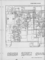
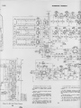
CHASSIS VIEWS
I
T106
POWER
TRANSFORMER
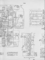
Figure 21
— Chassis Top
View (Showing Location
of
Major Components)
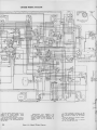
3
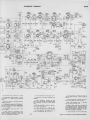
NOTE: IN
Figure 22
SOME RECEIVERS.
LI02
IS
USED
IN
PLACE OF TI04
— Chassis Bottom View (Showing Location of Major Components)
16
WAVEFORM PHOTOGRAPHS
Peak
to
peak voltages shown are nominal when
1
volt
peak
to
peak video signal
is
72 1 TS
applied to
Isl
video amplifier (V105).
c
Video Signal Input to 1st Video
Amplifier (At Pin 2 of V105)
Figure 25
— Vertical
(1.0 Volts,
P
to P)
.
'P-
ma
>
Figure 24
—Horizontal
(1.0 Volts,
P
to P)
'
'
S=
'
i
Output of
(Pin
Figure 25
—
(5.0 Volts,
1
Video Amplifier
of V105)
Vertical
P
Figure 26
to P)
to
P
Kinescope Socket)
—
Figure 28 Horizontal
(32 Volts, P to P)
to P)
Input to Grid Sync Amplifier
(Pin
1
ffl ffl
I
of V106)
—Vertical
Figure 29
P
to P)
Kinescope Grid
i^^WMIK
(8 Volts,
P
L106 and Green head
— Vertical
Figure 21
(32 Volts,
—Horizontal
(5.0 Volts,
Input to
(] unction of
c
1st
Figure 30
to P)
—Horizontal
(8 Volts,
P
to P)
Input to Sync Separator
(Pin 2 of VI 06)
—
—
Figure 31
Vertical
(90 Volts, P to P)
Figure 32 Horizontal
(90 Volts, P to P)
Output of Sync Separator
(Pin 6 of V106)
c
— Vertical
Figure 33
(10 Volts,
P
—
Figure 34 Horizontal
(10 Volts, P to P)
to P)
17
WAVEFORM PHOTOGRAPHS
72 ITS
— Vertical
Figure 35
(25 Volts,
PtoP)
Output of Integrating Network
(Junction of R138 and C125)
—
38 Plate of
Output Tube
(750 Volts, P to P)
(Pin 5 of V107)
Figure
Vertical
—
36 Grid of
Oscillator Tube
(175 Volts, P to P)
(Pin 1 of VI 07)
Figure
(Continued)
to
P)
(Junction of CI 29
—
to
P
(65 Volts,
Figure 39 Voltage Across Vertical Deflection
Coils (L108,
L109) (90 Volts, P to P) (At
Green Lead of T103
—
37 Input to Vertical
Output Tube
Figure
Vertical
Figure 40
and CI 30)
—Horizontal
Oscilla-
tor Waveforms and Sync Pulse
(20 Volts, P to P)
(Junction of C122 and C133)
Ground)
^Y
—
Figure 41
Horizontal Oscillator Control (45 Volts, P to P)
(Junction
Figure 44
R158 and R164)
— Grid of Horizontal
Output
(40 Volts, P to P)
(Pin 5 of V109)
—
Grid of Horizontal
Oscillator (400 Volts, P to P)
(Pin 4 of VI 08)
Figure 42
Figure
43
—Horizontal
Oscil-
Output (60 Volts, P to P)
(Junction of C135 and C163)
lator
—
—
Figure
46 Voltage
Across
Horizontal Deflection Coils
(Approx. 1100 Volts, P to P)
(Pin 4 or 6 of Vlll to
Figure 45 Plate of Horizontal
Output (Approx. 5000 Volts,
P to P) (Measured Through a
Capacity Divider
Connected
from Plate to Ground)
Ground)
CRITICAL LEAD DRESS
1.
Do not permit any strains
to
be
placed on the leads
2.
—
3.
Figure 47 Test Pattern Showing Out of Sync Condition
When Horizontal Hold Control
Is in a Counterclockwise Position Just Before Pulling Into
Figure 48 Test Pattern Showing Out Of Sync Condition
When Horizontal Hold Control
Is at the Maximum Clockwise
Sync
Position.
—
—
of R126, R157,
R158, R164, R165, R173, R188 and
R191. Do not permit these resistors to be exposed to the heat
of a soldering iron any more
than is absolutely necessary.
Dress the temperature compenapproxisating resistor R191
mately one-quarter inch from
the power transformer and the
chassis.
Dress all video coupling capaci-
and peaking coils up and
aivay from the chassis.
tors
4.
Contact between the r-f oscillafrequency adjustment screws
the oscillator coils or chanmust be
eyelets
switch
nel
avoided.
tor
and
18
i^Db.
CHASSIS WIRINQ DIAGRAM
--11
"
n
I
iT^
SE7J
'S'
J
MOTE
;
t
'
:^hzJ
(^
o Li-:^
The
Early production sets employed brightness and picture control #71784 in which
the brightness is the outer knob end picture, the center knob.
Late production,
shown in the above wiring diagram employs
control #73193 in which picture is the
outer knob and brightness the center.
front
fected
#72805
#73194
by
is
panel control decals are afthe control changes.
Decal
for control
Decal
#7 784.
1
#73193.
The operating instruction book
is
for
control
fected by the control change.
Book #49050-1
trol #71784.
19
is
also afInstruction
is
for sets employing con-
Figure 49
Supplementary sheet #49050-15 h
been issued to convert books for l
with sets employing control #73193. Su
sequent printings of late production
struct ion
books will be designated
iJ49050-2.
1
i
—Chassis
Wiring Diagram
CHASSIS
WmiNQ DIAGRAM
72
«E»-;i(eS--.»N.-_^
^
^~Jb1I9
to ion trap
UlMiNEJ?-"^^
*«vJl f
—f'o^l-
The front panel control decats are affected
#72805
#73194
by
is
is
the
control
changes.
for
control #7 1 784.
for control #73193.
The operating instruction book
fected by the control change.
Book #49050-1
trol
is
for sets
Decal
Decol
oiso afInstruction
is
employing con-
Supplementary sheet #49050- S
has
been issued to convert -1 books for use
with sets employing control #73193.
Subsequent printings of late production instruction
books will be designated as
1
£r49050-2.
#71784.
19
In
early production receivers, an EM
type of ion trap mognet was employed and
was connected as shown by the dotted
lines.
R 96 was omitted in receivers employon EM type magnet.
R 97 was employed only in receivers
1
ing
1
with the
Figure 49
—Chassis
Wiring Diagram
247-ohm focus
coil.
72 ITS
-"-
<
^
Direction of arrows
clockwise rotation,
49050-15
has
books for use
6^73193.
Subproduction
in-
:iesignated
as
In
early production receivers, an EM
type of ion trap magnet was employed and
was connected as shown by the dotted
All voltages measure
and with picture
coni
Voltages should hold
17 v. a-c supply.
lines.
1
R196 was omitted in receivers employan EM tvpe magnet.
R197 was employed only in receivers
with the 247 -ohm focus coil.
ing
resistance vqIl
Coil
are not shown.
some
caused
Figure 30
—R-F Unit Wiring Diagram
20
codas,
their
receivers,
changes
in
lug
in
o
electrolytic
identificatioi
72 ITS
SCHEMATIC DIAGRAM
In
early production receivers Qr\ EM
type of ion trap magnet was employed and
was connected as shown by the dotted
ines.
R196 was omitted
ng an
EM
In
some
In
I
some
n
—
Figure 50
codas,
jR-F Unit
20
Wiring Diagram
their
in
lug
substitutions
have
component lead
color
receivers,
changes
In
electrolytic capacitor values
identification markings.
and
CH2
21
some
is
receivers
employ-
the antenna trap
and C22) may be omitted.
receivers,
(LSI, L82, C21
caused
in
type magnet.
receivers, the bottom end
connected to pin 4 of Vlll
of
SCHEMATIC DIAGRAM
721TS
VI 14
6bA6
SOUND
15T.
AM
resistance values in ohms.
All
capacitance values
and
above
in
1
MMF
less
K
:
than
unless
1000.
In
some
sets
MF
In
some
sets
in
1
1-F
R108
is
connected to ~!4V.
In
used
otherwise
L122, R195 and R193 are
All voltages
ance of the focus
lines.
with the
R195 was omitted
±20%
with
ing
than
ohm
(L81, L82, C21
substitutions
hove
CI 42
component lead
color
Voltages should hold
7 v. a-c supply.
R197
within
in
receivers
employ-
In
resistance values
less
1
some
In
receivers,
caused changes
their
in
lug
employed
247-ohm focus
only
in
receivers
coil.
is connected
in place.
However, if transients are produced on high contrast pictures, the link should be opened.
See figure 49 for location of the link.
the antenna trap
and C22) may be omitted.
receivers,
ore not shown.
codes,
was
Optional video peaking Is provided by
the video peaking link.
Normally the link
an EM type magnet.
1
some
production receivers the resistcoil was 247 ohms.
In
early production receivers an EM
type of ion trap magnet was employed and
was connected as shown by the dotted
measured with "VoltOhmyst"
and with picture control counterclockwise.
In
receivers, a single coil, L102, is
place of T104.
LI 02 is tuned to
In early
Direction of arrows at controls indicates
clockwise rotation.
Coil
in
omitted.
noted.
I
some
26 mc.
in
electrolytic capacitor values
identification markings.
and
21
some
is
receivers, the bottom end of
connected to pin 4 of VII 1.
In
Figure 51
some
receivers,
R-149
is
3300 ohms.
— Overall Circuit Schematic Diagram
J
REPLACEMENT PARTS
721TS
STOCK
STOCK
DESCRIPTION
No.
RF
UNIT ASSEMBLY
71473
KRK2B1
75066
75067
—
Bracket — Vertical
Board
2 contact terminal board (used as antenna
terminal board) on top of R-F unit
71467
bracket ior holding R-F oscillator
71468
Capacitor— Ceramic,
C17)
72122
71469
71479
Cll,
#2 and #3 and #4
72597
-front section (L56, L58, L60)
Coil
Channel #3 converter grid
72552
71480
72553
71481
71472
71471
71492
71491
71490
—
—
—
—
—
—Channel
—Channel
channel #2
Coil — Channel
Coil
Coil
71498
71597
72743
71465
72744
71487
—front
or rear
oscillator coil
(L7,
L8)
oscillator coil
—
#3
#4
#4
#5
coil
rear section (L57)
amplifier plate coil^front or
r-f
— rear
—
—rear
section (L55, L82)
converter grid or r-f
front or rear section (Lll, L12,
amplifier
r-f
(L26,
front
(L77)
oscillator coil
oscillator coil
front
front
coils or front and rear r-f amplifier plate coils adjustable core and stud or channel #13 front and
rear converter grid coils or front and rear r-f amplifier plate coils adjustable core and stud
Core Channel #13 front and rear oscillator coils
adjustable core and stud
Detent Detent mechanism and fiber shaft
Disc Rotor disc for fine tuning control (Part of C15)
71476
71474
or
26-2
70638
73101
Capacitor—Tubular,
.05 mfd.,
Capacitor
oil
70618
Capacitor—Tubular,
72740
71780
71436
to
72736
—
—
—
—
—
—
—
—
—
—
—
—Molded
.01
mfd., 400 volts (C149, C157,
paper,
.01
.02 mfd.,
.05 mfd.,
mfd.
400 volts (C143,
400 volts (C167)
400 volts (C103, CI 15,
—Tubular,
71781
600 volts (C138)
impregnated, 0.1 md., 1000
C140)
0.25 mfd., 400 volts (ClOl, C117,
C129, C137, C161)
Capacitor Electrolytic, dry, 24 mfd., 300 volts (C160)
Capacitor Electrolytic, comprising 1 section of 80
mfd., 450 volts, and 1 section of 10 mfd., 450 volts
(C127A, C127B)
Capacitor Electrolytic, comprising 1 section of 250
mfd., 10 volts, and 1 section of 1000 mfd., 6 volts
(C132A, C132B)
Capacitor Electrolytic, dry, comprising 1 section of
10 mfd., 400 volts; 1 section of 30 mfd., 350 volts;
and 1 section of 30 mfd., 250 volts (C116A, C116B,
—
—
—
—
C116C)
71782
W
r-f
KCS
—
—
—
volts (C130,
Resistor 47 ohms, V2 watt (R8)
Resistor— 150 ohms, V2 watt (R3, Rll, R13)
Resistor— 1000 ohms, V2 watt (R4, R12, R14)
Resistor— 4700 ohms, V2 watt (Rl, R2, R7)
Resistor— 10,000 ohms, V2 watt (R5)
Resistor— 100,000 ohms, V2 watt (R9, RIO)
V2 watt (R6)
1 megohm,
Resistor
Ring Retaining ring for drive
Screw #4-40 x 15/32" adjusting screw for coils
L54, L56, L58, L60, L62
binder head screw for adjustScrew #4-40 x
ing coils L66, L68, L70, L72, L74, L76
Segment Converter grid section rear segment less
coils
26-1,
——
Capacitor-Tubular,
Capacitor—Tubular,
for
—
—
—
—
—
trap (L81, L82, C21. C22)
C118, C120)
—
—
—
Drive — Fine tuning drive
channels #6 and #13
Form — Coil form only
—less winding
converter grid coupling loop
Loop — Oscillator
—
(T3,
Trap— Antenna
70611
70615
oscillator coils
coils
71462
30732
30880
34766
30494
3078
3252
30652
14343
71475
(Tl)
volts (C139)
coil (L79)
front
stator
71770
(L78)
coil (L80)
i-f
oscillator
fine
C158)
Capacitor
C144)
70602
—
—
amplifier
—
section
L52)
—
plate
—rear section
Coil — Channel #13
section
—
Coil — Channel #13
choke
Coil — Converter grid
Coil- Heater choke
Connector — Segment connector
adand rear
Core — Channel #6
justable core and stud
and fear converter grid
Core — Channel #6
r-f
for
Capacitor— Tubular,
oscillator,
—
fine
to
70610
39660
72524
72771
—
—
#6
for
70601
70622
70606
70627
71518
73094
71450
71501
section (L59)
front or
r-f amplifier plate coil
or channel #5 converter grid coil
section (L9, LIO, L35, L36)
#5 oscillator coil rear section (L61)
#5 oscillator coil front section or
oscillator coil
less coils
Bearing R-F shaft bearing assembly
Board "Antenna" board two contact solders to
i-f cable
Capacitor— Mica, 5 mmf., 1500 volts (C1B5)
Capacitor Mica, 10 mmf. (CI 13)
Capacitor Mica, 47 mmf. (C169)
Capacitor Mica, 100 mmf. (C119)
Capacitor— Ceramic, 100 mmf. (CllO)
Capacitor— Mica, 120 mmf. (C122, C133)
Capacitor- Mica, 180 mmf., 1000 volts (C162)
Capacitor— Mica, 270 mmf., 1000 volts (C104, C108,
C112, C156)
Capacitor—Mica, 390 mmf., 1000 volts (C135, C164)
Capacitor High-voltage capacitor, 500 mmf. (C142)
Capacitor— Ceramic, 1500 mmf. (C102, C105, C106,
C107, cm, C114, C145, C146, C150)
Capacitor Mica, 2200 mmf. (C163)
Capacitor Mica, 4700 mmf. (C126)
Capacitor Mica trimmer, consisting of 1 section of
10-160 mmf. and 2 sections of 40-370 mmf. (C136A,
C136B, C136C)
Capacitor Tubular, .0025 mfd., 400 volts (C154,
C155)
Capacitor Tubular, .002 mfd., 400 volts (C123)
Capacitor Tubular, .002 mfd., 600 volts (C134)
Capacitor Tubular, .005 mfd.. 400 volts (C124, C125)
Capacitor— Tubular, .005 mfd.. 600 volts (C159)
Capacitor Tubular, oil impregnated, .035 mfd., 600
72809
72615
39620
39628
45469
39630
73102
73091
oscillator coil
amplifier plate coil
L37, L38, L63, L64)
Channel #13 converter grid or
Coil
plate coil rear section {L25, LSI)
Channel #13 converter grid or
Coil
coil
71489
71488
71506
71505
71493
71497
L32)
Socket
Spring
Spring
KCS
LB, L29, L30, L33, L34)
Coil— Channel
segment
section rear
—Lead tube shield V3
—Tube socket—miniature
—Snap spring hold
tuning shaft
—Retaining spring R-F
tube shield
Stator— Oscillator
tuning
and bushing
C15)
Transformer— Antenna transformer
Transformer— Converter transformer
C20)
Shield
71494
71461
75068
71466
71894
72857
—
71470
—Oscillator
TELEVISION CHASSIS
—
—
—
Segment
r-f
(Part of
—
—
section (L31,
Channel
Coil
Coil Channel
rear section
Coil Channel
Channel
Coil
rear section
front or rear
grid section front segment less
amplifier plate section front segment
less coils (Part of S2, S3)
Segment^Oscillator section front segment less coils
(Part of S4)
72951
71507
72811
73239
Channel #1 rf amplifier plate coil front oi
rear section or channel #1 converter grid coil
front or rear section (LI, L2, L27, L28)
Channel #1 oscillator coil front or rear secCoil
tion (L53, L54)
Channel #2 and #3 r-f amplifier plate coil
Coil
front or rear section or Channel #2 and #4 converter grid coil
front or rear section (L3, L4, L5.
Coil
—Converter
or
(Part of S4)
mmf. (C13)
Capacitor Ceramic, 1.5 mmf. {C3, C4)
Capacitor Ceramic, 2.2 mmf. (CIO)
Capacitor Ceramic, 4.7 mmf. (C6, C7, CI 2)
Capacitor Ceramic, 10 mmf. (C19)
Capacitor Ceramic, 22 mmf. (C14)
Capacitor— Mica, 270 mmf. (CI 8)
Capacitor— Ceramic, 270 mmf. (CI, C2)
Capacitor— Ceramic, 1500 mmf. (C5, C8, C9,
0.68
—
—
—
—
—
Segment
coils
tube shield
71504
71500
71502
71520
45466
33101
65401
71540
71501
DESCRIPTION
No.
—
Capacitor Electrolytic, comprising 1 section of 40
mfd., 450 volts; and 1 section of 10 mfd., 350 volts
(C131A, C131B)
Capacitor Electrolytic, comprising 1 section of 40
mfd., 450 volts; 1 section of 40 mfd., 150 volts;
and 1 section of 130 mfd., 50 volts (C128A, C128B,
—
C128C)
71426
71529
71793
amplifier plate section rear segment
less coils (Part of S2, S3)
22
Coil—First or third pix i-f coils (LlOl, L103)
Coil— Peaking coil (L105, R119, L106, R123)
Coil— Peaking coil (L104, L107)
REPLACEMENT PARTS
STOCK
STOCK
DESCRIPTION
No.
71528
71429
71449
73233
71789
71521
Coil—Peaking coil
Coil— Width control
(1,122,
R195)
71457
71437
71783
Cover— Insulating
72772
71510
Cover— Insulating
73193
72735
71440
71443
72734
71441
71785
14983
30648
30653
coil (L112)
Coil
coil (LI 13)
Coil— Focus
coil
for
electrolytics,
for
electrolytics,
72738
72739
30652
71452
72741
72773
71508
9914
72516
72927
31251
73249
71453
71775
71774
71416
RCA
#71436 and #71782
cover for electrolytic. RCA #72736
Rubber cushion lower for deflection yoke
—
—
—
Cushion — Rubber cushion — upper —
deflection yoke
hood
Grommet — Rubber grommet
mount socket RCA
#73249
required)
Magnet —Ion trap magnet (PM type)
Fuse— 0.25 amp., 250 volts
Magnet— Ion trap magnet
LI
(EM type)
Nut— #8-32 speed nut
unit shield
required)
Nut — #8-32 wing nut
mounting focus
quired)
Plate —Bakelite mounting plate
electrolytic caCushion
hood
71509
37396
for
to
(2
73301
73600
71792
72737
71455
18469
(Fl)
(LI 10,
for
11)
r-f
(2
for
for
30650
8064
3252
72893
72892
30180
72891
30493
11959
19232
Resistor— 100,000
Resistor— 100,000
Resistor— 120,000
Resistor— 120,000
Resistor— 150,000
Resistor— 180,000
Resistor— 270,000
13961
30880
5164
19233
71916
34766
30731
30733
71986
30694
30494
71987
30734
14659
14250
3078
12876
30436
36714
70723
30492
72928
71772
coil (3 re-
pacitor
2-prong male plug for power cord
Resistor 3.3 ohms,
watt (R187)
Resistor 5.1 ohms, '/2 watt (R190)
Resistor— 39 ohms, V2 watt (R103, R112)
Resistor 39 ohms, 1 watt (R196)
Resistor— 47 ohms, V2 watt (R120, R192)
Resistor 82 ohms, 1 watt (R162)
Resistor 82 ohms, V2 watt (R174)
Resistor
150 ohms, V2 watt (R115)
Resistor— 560 ohms, 'A watt (R147)
Resistor— 680 ohms, 1 watt (R168, R169)
Resistor— 1000 ohms, 1 watt (R185)
Resistor— 1000 ohms, V2 watt (R104, R109, RllO, R113,
R117, R125, R150, R178)
Resistor— 1200 ohms, V2 watt (R175)
Resistor— 3300 ohms, V2 watt (R122, R193)
Resistor— 3300 ohms, 1 watt (R124)
Resistor 3900 ohms, V2 watt (R149)
Resistor 4700 ohms. V2 watt (R118)
Resistor 4700 ohms. 1 watt (R163)
Resistor 5600 ohms, V2 watt (Rill)
Resistor 6800 ohms. V2 watt (R116, R132)
Resistor 8200 ohms. V2 watt (R137, R138, R172)
Resistor
10,000 ohms '/2 watt (R106, R186, R188)
Resistor Wire wound, 10,000 ohms, 10 watts (Ri97)
Resistor— 12,000 ohms, "^ watt (R107)
Resistor— 15,000 ohms. '/^ watt (R102. H114)
Resistor
15,000 ohms, 1 watt (R130)
Resistor— 22,000 ohms, V2 watt (R136, R177)
Resistor Temperature compensating, 30,000 ohms,
Vi watt (R191)
Resistor— 56,000 ohms, Vz watt (R142)
Resistor— 82,000 ohms, V4 watt (R170)
Resistor— 100,000 ohms, V2 watt (R133, R145, R18I,
71448
71513
72067
11956
32813
30732
31959
—
Plug
—
—
—
—
—
—
73150
73708
71424
%
71427
71776
72770
71778
71777
—
Wire wound, comprising 1 section of 1125
ohms, 20 watts, and 1 section of 610 ohms, 20
watts (R153A, R153B)
Resistor Voltage divider, comprising 1 section of
8200 ohms, 5 watts; 1 section of 35 ohms, 0.8 watt;
and 1 section of 100 ohms, 2 watts (R1S4A, R154B,
R154C)
Resistor— 1 megohm, V2 watt (R121, R127, R131,
Resistor
—
— megohm, watt (R167)
— megohms, watt (R139)
— megohms, watt (R146)
— megohms, watt (R165)
— megohms, watt (R134)
— megohms, watt (R140, R171)
— 10 megohms, watt (R180)
Screw — #8-32 wing screw
deflection yoke
quired)
Sleeve —Rubber sleeve
focus
Socket;— Kinescope socket
Socket—Single contact female socket
C142
Socket — Tube socket
8016 tube
Socket—Tube socket, miniature
Socket —Tube socket, miniature (with shield attached)
Socket — Tube socket, noval wafer type
Socket—Tube socket, octal
Socket—Tube socket,
ceramic, plate mounted
Stud — Mounting stud
focus
required)
Transformer — Vertical oscillator transformer (T102)
Transformer—Vertical output transformer (T103)
Transformer—Horizontal
output
and high-voltage
transformer (T105)
Transformer — Power transformer, 115
60 cycle
(T106)
Transformer— Power transformer, 115
50 cycle
(T106)
Transformer—Second pix
(T104, C121)
Transformer—Sound
transformer
T107 (C147,
C148, L116, L117)
Transformer—Sound discriminator transformer T108,
(C151, C152, C153, L118. L119)
Transformer— Audio output transformer (T109)
Transformer—Horizontal oscillator transformer (L121)
Resistor
Resistor
Resistor
Resistor
Resistor
Resistor
Resistor
1
1
1.5
V2
2.2
V2
3.3
1
3.9
V2
V2
6.8
V2
for
(3
for
re-
coil
for
for
octal,
for
coil (2
volt,
volt,
i-f
i-f
Trap—Sound
CI 09)
(L108, L109, LI 14, LI 15, C141,
trap (TlOl.
Yoke—Deflection yoke
RlOl, R151)
SPEAKER ASSEMBLY
71797
Speaker
92565-lW
—
4" x 6"
elliptical
E.M.
speaker complete
with con.e and voice coil
MISCELLANEOUS
72786
—
—
—
—
—
—
—
—
X1648
72819
72805
73194
71984
71598
72113
72818
71539
—
—
—
—
Bracket— Decorative bracket
panel
Decal — Control marker decal (use with control
#71784)
Decal — Control marker decal (use with control
#73193)
Decal — Trade mark decal
Escutcheon — Channel marker escutcheon
Feet — Rubber
cabinet
required)
Glass —Safety glass
Slide— Kinescope centering slide with rubber cushion
required)
Knob— Channel selector knob
Knob—Fine tuning knob
Knob—Horizontal hold or picture control knob
Knob — Volume control and power switch knob
Knob—Volume control and power switch, vertical
hold or brightness control knob
Plate — Retaining plate complete with wing nut and
spring
top section
cabinet
required)
Spring—Retaining spring
knobs, #71535, #71537
Back Cabinet back
Board Baffle board
for front
feet for
(4
(4
71534
71533
71536
71537
71535
R182)
ohms,
ohms,
ohms,
ohms,
ohms,
ohms,
ohms,
Resistor— 330,000 ohms, Vi watt (R179)
Resistor— 470,000 ohms, '/4 watt (R176, R184)
Resistor— 560,000 ohms, V2 watt (R157. R189)
R143, R160)
71993
31449
30649
72632
70249
31071
30992
71456
#71780 and #71781
cover
DESCRIPTION
No.
—Horizontal linearity control
(L120)
Connector— Kinescope anode connector
Connector—Hiah-voltage capacitor lead connector
Control — Brightness and picture control (R108, R128)
(use with decal #72805)
Control —Brightness and picture control (R1D8, R128)
(use with decal #73194)
Control —Focus control (R129)
Control — Height control (R141)
Control — Horizontal
or
vertical
centering control
(R152, R166)
Control — Vertical and horizontal hold control (R144,
HI 56)
Control — Vertical linearity control (R148)
Control — Volume control and power switch (R183,
SlOl)
Cord— Power cord complete with plug
Cover —Insulating
cover
RCA
71784
72 ITS
(Continued)
watt (R173)
watt (R164)
'/i watt (R135)
1 watt (R1S9)
Vi watt (R155)
V2 watt {R158)
1 watt (R126)
72817
V2
1
for
14270
30330
4982
71538
of
and #71534
Spring—Retaining spring
—Retaining
—Spring
Spring
Spring
for
knob #71536
spring for knob
clip for
escutcheon
APPLY TO YOUR RCA DISTRIBUTOR FOR PRICES OF REPLACEMENT PARTS
23
front (2
for
#71533
.
^