1
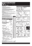
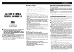
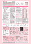
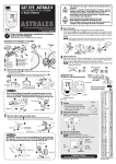
ENG CATEYE ADVENTURE CYCLOCOMPUTER CC-AT200W U.S. Pat. Nos. 5236759/6957926 Pat./Design Pat. Pending Copyright© 2011 CATEYE Co., Ltd. CCAT2W-110930 This device complies with Part 15 of the FCC Rules. Operation is subject to the following two conditions:(1)This device may not cause harmful interference, and (2) this device must accept any interference received, including interference that may cause undesired operation. Modifications The FCC requires the user to be notified that any changes or modifications made to this device that are not expressly approved by CatEye Co., Ltd. May void the user ’s authority to operate the equipment. WARNING / CAUTION •• Do not concentrate on the computer while riding. Ride safely! •• Install the magnet, sensor, and bracket securely. Check these periodically. •• If a child swallows a battery, consult a doctor immediately. •• Do not leave the computer in direct sunlight for a long period of time. •• Do not disassemble the computer. •• Do not drop the computer to avoid malfunction or damage. •• When using the computer installed on the bracket, change the MODE by pressing on the four dots below the screen, or by pressing on the SSE simultaneously, to start or stop the timer. Pressing hard on other areas may result in malfunction or damage to the computer. •• Be sure to tighten the dial of the FlexTight bracket by hand. Tightening it strongly using a tool, etc. may damage the screw thread. Before using the computer, please thoroughly read this manual and keep it for future reference. Battery case cover Operation of buttons when the computer is mounted on the bracket MENU MODE SSE km/h mph: Speed unit : Wheel size icon : Sensor signal reception icon MODE+SSE Press only the computer body. 1 1. Press and hold the MENU button. Format (initialize) 2. Press the AC button. 3. Release the AC button. 4. Release the MENU button. Press the SSE button with the computer body together. SSE button by itself does not function. MENU AC the speed and temperature unit 2Select When MODE and SSE are pressed simultane- Unit selection MENU Register the setting the tire circumference 3Enter Enter the tire circumference of your bicycle in mm. **Refer to the tire circumference reference table. Register Increase Move digits (By pressthe setting the value ing simultaneously) MODE MODE+SSE After changing the battery, or when the computer displays an error, restart the computer according to the following procedure. 111 Press the AC button on the back of the computer. 222 Set the clock. Refer to “Preparing the computer 5”. ETRTO 47-203 54-203 40-254 47-254 40-305 47-305 54-305 28-349 37-349 32-369 28-540 32-540 25-559 32-559 37-559 40-559 47-559 50-559 54-559 57-559 58-559 75-559 28-590 37-590 37-584 MENU the sensor ID 4Set Hold the computer body close to the sensor (20 - 70cm), and press and hold the RESET button on the sensor with a sharp object. Sensor will randomly generate an ID number for the computer body to receive, and displays on the screen. If successfully synchronized, screen will automatically move on to Clock setting screen. 20-571 23-571 **When setting the sensor ID, place the sensor at least 20 cm (approximately 8 inches) away from the computer. Press and hold the RESET 25-571 button, the sensor will send the ID when releasing the button. 40-590 40-584 **The computer is on standby for 5 minutes while setting the sensor ID. It dis25-630 plays “ERROR”, and cancels the ID when no ID signal is received during the 28-630 standby, or you press MODE and SSE simultaneously. Screen will move on to 32-630 37-630 clock setting. Without the ID, speed cannot be detected and displayed. Be sure 18-622 to set the sensor ID according to “Sensor ID setting” on the menu screen. 19-622 **Original ID is saved if you cancel the ID. 20-622 23-622 Move to Clock Start the ID setCancel the ID or 25-622 Setting when no 28-622 ting (By pressreset (By pressing 30-622 ing & holding) MODE+SSE simultaneously) MENU ID has been set RESET 32-622 5 When MODE and SSE are pressed simultaneSet the clock 35-622 38-622 40-622 42-622 44-622 45-622 47-622 54-622 60-622 ously, “Displayed time”, “Hour”, and “Minute” will appear, in this order. Switch the screen 24h ↔ 12h, Register or move digits or increase the setting (By pressing MODE the value MENU (Finish) MODE+SSE simultaneously) Measure wheel circumference (L) of your bike To get the most accurate calibration do a wheel roll out. With the valve stem perpendicular to the ground, mark the pavement at the valve stem. With the riders weight on the bike, roll the wheel one tire revolution in a straight line and mark the ground when the valve stem is perpendicular to the ground again. Measure the distance in millimeters. This is the most accurate wheel calibration number. How to install the unit on your bicycle 2 Tire size 12x1.75 12x1.95 14x1.50 14x1.75 16x1.50 16x1.75 16x2.00 16x1-1/8 16x1-3/8 17x1-1/4 (369) 18x1.50 18x1.75 20x1.25 20x1.35 20x1.50 20x1.75 20x1.95 20x1-1/8 20x1-3/8 22x1-3/8 22x1-1/2 24x1.75 24x2.00 24x2.125 24x1(520) 24x3/4 Tubuler 24x1-1/8 24x1-1/4 26x1(559) 26x1.25 26x1.40 26x1.50 26x1.75 26x1.95 26x2.10 26x2.125 26x2.35 26x3.00 26x1-1/8 26x1-3/8 26x1-1/2 650C Tubuler 26x7/8 650x20C 650x23C 650x25C 26x1(571) 650x38A 650x38B 27x1(630) 27x1-1/8 27x1-1/4 27x1-3/8 700x18C 700x19C 700x20C 700x23C 700x25C 700x28C 700x30C 700x32C 700C Tubuler 700x35C 700x38C 700x40C 700x42C 700x44C 700x45C 700x47C 29x2.1 29x2.3 5 3 1340 1340 1350 1450 1460 1490 1515 1565 1545 1615 1770 1785 1890 1925 1965 1753 1785 1795 1905 1913 1950 2005 2010 2023 2050 2068 2070 2083 2170 1970 2068 2100 1920 1938 1944 1952 2125 2105 2145 2155 2161 2169 2070 2080 2086 2096 2105 2136 2146 2155 2130 2168 2180 2200 2224 2235 2242 2268 2288 2326 7 6 L (mm) 935 940 1020 1055 1185 1195 1245 1290 1300 1Bracket band 2Bracket 3Nut 4Sensor 5Magnet 6Sensor rubber pad 7Bracket rubber pad 8Nylon ties (x2) 4 1 Tire circumference reference table 40-355 47-355 32-406 35-406 40-406 47-406 50-406 28-451 37-451 37-501 40-501 47-507 50-507 54-507 25-520 ously, “Speed unit” or “Temperature unit” can be selected. Select “km/h” or “mph” for the speed unit, and “°C” or “°F” for the temperature unit. Press MENU to register. MODE+SSE In order to prevent any interference with the sensor signal, the transmission range is designed to be 20 to 70 cm, in addition to use of the ID code. (This receiving range is only a reference.) Please note the following points. •• To use this unit, the sensor ID has to be set. •• Two different IDs, ID1 and ID2, can be registered to this unit, which are identified automatically. •• The computer cannot receive when the distance between the sensor and computer is too long. Temperature drop and battery drain may worsen the receiving sensitivity even if they are within the transmission range. Interference may occur, resulting in incorrect data, if the computer is: •• Near a TV, PC, radio, motor, or in a car or train. •• Close to a railroad crossing, railway tracks, TV stations and/or radar base. •• Using with other wireless devices, or some particular battery lights. Click MODE When using the computer for the first time or resetting to the factory default setting, format according to the following procedure. MODE Wireless Sensor **The stored sea level altitude, home altitude, speed unit, wheel size, sensor ID, countdown distance, selected wheel, AT setting, total distance and total altitude gain will not be changed after pressing the AC button. Pressure sensor AC Switch the screen (By pressing simultaneously) •• When cleaning the computer, bracket and sensor, do not use thinners, benzene, or alcohol. •• A temperature sensor is built in the computer. If the sensor is heated by direct sunlight or body heat, it may not indicate the temperature correctly. •• The altitude data with this unit is for reference only; accordingly, do not use this unit as a measuring device for professional use. •• Dispose of used batteries according to local regulations. •• LCD screen may be distorted when viewed through polarized sunglass lenses. How to restart Preparing the computer 0678 4 8 Install the sensor and magnet A The distance from the computer to the sensor is within the transmission range. B The magnet passes C The clearance between the sensor and magthrough the sensor zone. net is 5 mm or less. Sensor zone 4 SENS OR ZONE Max 70 cm SE N ZOSOR NE 5 4 5 mmm 5m Right front fork (inside) **The magnet may be installed anywhere on the spoke if the above installation conditions are satisfied. 1 Install the sensor 4 6 2 Install the magnet Right front fork Pull securely Spoke on the right 8 5 SEN S ZO OR NE SENS OR ZONE **Install the sensor to the front fork as high as possible. To the sensor zone 3 Attach the bracket to the stem or handlebar When attaching the bracket to the stem 7 2 Stem Cut 1 Caution: Round off the cut edge of the bracket band to prevent injury. When attaching the bracket to the handlebar **On account of the receiving sensitivity, attach the bracket so that the computer is kept horizontal. Handlebar 7 1 3 2 4 Remove/install the computer While supporting it by hand, Click **For wing type handlebar or oversized stem, bracket can be mounted using the Bracket Holder and nylon ties. (Option) 2 push it out as if lifting the front up L mm **After installation, check that the speed is displayed on the computer when gently turning the front wheel. When it is not displayed, check the positions of A , B , and C . 1 Operating the computer [Measuring screen] Starting/Stopping measurement You can select the Auto mode (automatic measuring) or manual mode. During measurement, km/h or mph flashes. The maximum speed and total distance are updated regardless of starting/stopping measurement. •• Auto mode ( on) Measurements start automatically when the bicycle is in motion. •• Manual mode When the computer is mounted on the bracket, start/stop measuring by pressing the MODE and SSE buttons simultaneously. **For switching between Auto and Manual mode, refer to “Auto mode setting” on the menu screen. Switching computer function Current speed 0.0(4.0) – 105.9 km/h [0.0(3.0) – 65.0 mph] Selected mode at the middle display Selected mode at the bottom :Pace arrow Indicates whether the current speed is faster ( ) or slower ( ) than the average speed. :Auto mode icon :Low battery indicator of the computer Measuring screen Temperature -20 – 60 ˚C [-4 – 140 ˚F] Sea Level Altitude -500 – 9000 m [-1640 – 29600 ft] Slope (%) -99% – +99% Bottom display Caution: When Auto mode is Off, elapsed time counts even if the bicycle is not in motion. After measurement, be sure to press MODE and SSE simultaneously to stop measuring. Sea level altitude correction This unit determines the altitude by converting the change in atmospheric pressure and temperature; therefore, it may cause deviation from the actual sea level altitude. It is recommended to correct the sea level altitude just before measurement, using either the following methods. •• ADJUST (sea level altitude correction): Enter the altitude at the current point. Enter the actual value at the point where the sea level altitude is known, such as along the seashore, or at a sign on the mountain, etc. 0:00 – 23:59 or 1:00 – 12:59 Countdown distance Tm Elapsed Time Shortcut A 0:00’00” – 99:59’59” MODE Trip Distance 0.00 – 9999.99 km [mile] Once the target trip distance is set, the unit displays the countdown distance to the target, and notifies at arrival. When the unit reaches the target distance, the countdown distance appears and the value flashes. The screen returns to the original display in 5 seconds. **The target distance is set on the menu screen “Countdown distance setting”. Move to the countdown distance setting screen by pressing MENU, MODE, or the relevant shortcut from the measuring screen. Dst Dst 2 Trip Distance-2 •• HOME (home altitude setting): Preset a specific sea level altitude. Preset the sea level altitude at your home in advance. Move to the HOME screen, and then return to the measuring screen by pressing MENU or the relevant shortcut. Then, the sea level altitude changes to the preset value. You can start with the correct sea level altitude by setting home altitude before stating from your home. **The sea level altitude is corrected on the menu screen “Sea level altitude correction”. Move to the sea level altitude correction screen by pressing MENU or the relevant shortcut from the measuring screen. Clock 0.00 – 9999.99 km [mile] (By pressing & holding) Shortcut to sea level altitude correction. Valid while the computer is receiving no signal from sensor. MODE *1 **It is updated when the measurement screen is displayed (while measuring: every 3 seconds, while not riding: every 20 seconds). **The altitude measurement is updated every 3 seconds during measurement (when counting the elapsed time), but not updated when measurement stops. **Press and hold MODE and SSE simultaneously on the setting screen to reset the corrected value to the default (a value according to ISO2533). Pressing the MODE changes the middle/bottom row display. Middle display Temperature�����������The current temperature is displayed. Av Average Speed*2 Changing the computer settings [Menu screen] Pressing MENU on the measuring screen moves to the menu screen for setup change. Once inside the menu screen, press the MODE button to scroll through setup items. Press MODE+SSE to enter the edit screens. Change cannot be done if there is an incoming signal and timer is active. Shortcut :When using a shortcut, the sea level altitude correction screen or the countdown distance setting screen is not displayed as shown in the figure below. It moves directly to the edit screen. Sea level altitude correction Wheel selection Auto mode setting 0.0 – 105.9 km/h [0.0 – 65.0 mph] MODE Ascending Altitude 0 – 999999 m [ft] Mx Maximum Speed MODE Countdown distance setting MENU 0.0(4.0) – 105.9 km/h [0.0(3.0) – 65.0 mph] MODE MODE Wheel size entry MODE Clock setting Sensor ID setting Shortcut B Countdown Distance 9999.90 – 0.00 km [mile] MODE Shortcut to countdown distance setting. Valid while (By pressing & holding) the computer is receiving no signal from sensor. Total Altitude Gain Odo Total Distance 0 – 99999 0.0 – 9999.9 / 10000 – 999999 km [mile] / 100 – 99999 x 1000 m [ft] *** With the computer installed on the bracket, press on the four raised dots on the face of the computer. *** If Tm exceeds approximately 27 hours or Dst exceeds 9999.99 km, .E (Error) is displayed as the average speed. Reset data. Resetting data While displaying any data other than Dst-2, pressing and holding the MODE and SSE simultaneously resets the measurement data to 0. While displaying Dst-2, pressing and holding the MODE and SSE simultaneously resets only Dst-2 to 0. In both cases, the total distance and total altitude gain are not reset. Power-saving mode If the computer has not received a signal for 10 minutes, power-saving mode will activate and only the clock will be displayed. When the computer receives a sensor signal again, the measuring screen reappears. If 60 minutes’ inactivity elapses, power-saving mode will change to SLEEP mode. Pressing the MODE in SLEEP mode brings up the measuring screen. Altitude measurement This unit detects the change in atmospheric pressure and temperature using a pressure sensor built in the computer, and converts it to the altitude using the relation between the altitude and pressure of ISO 2533 (Standard atmosphere), which was developed based on the international standard atmosphere specified by the International Civil Aviation Organization (ICAO). Accordingly, the measurements tend to change, even at the same point, according to the atmospheric pressure due to the weather condition. Furthermore, the measurements may change more than 30 m from the early morning to the evening even under a stabilized weather condition. The measurements may be incorrect in the following place or environment. •• When the atmospheric pressure and temperature change significantly due to a rapid weather change. •• In the place where the atmospheric pressure is regulated, such as inside an airplane. •• The altitude data may change temporarily when the temperature changes rapidly by getting out of a room, etc. It may return to a correct value after a while. Altitude measurement This unit has four altitude-related functions and temperature function. Sea level altitude����The current sea level altitude is displayed. **For effective use of the sea level altitude, refer to “Sea level altitude correction”. Slope����������������������Measures slope in percent unit, where 45 degree angle being 100%. **It is updated every 3 seconds, calculating from several times of the change in altitude and the trip distance. Slope update may be delayed. Abnormal data may also be temporarily displayed when speed quickly changes or during low-speed. Menu screen MODE MODE Speed/temperature unit selection MODE MODE Total distance manual entry Setting change **After changing, be sure to press MENU to register the setting. ( b y p r e s s i n g **If the setting screen is not touched for a minute, the measurMODE+SSE simultaneously) ing screen appears without data changes. Sea level altitude correction Shortcut A : MODE (By pressing & holding) → Back to the previous measuring screen ����������������������������������Select ADJUST (sea level altitude correction) or HOME (home altitude setting) by pressing MODE. When MODE and SSE are pressed simultaneously,“+/- selection” or “Move digit” can be selected, and pressing MODE increases the +/- selection or the value. Enter the desired altitude. **For details, refer to “Sea level altitude correction”. Countdown distance setting Shortcut B : MODE (By pressing & holding) → Back to the previous measuring screen �������������������������������Pressing MODE increases the value and pressing MODE and SSE simultaneously moves to the next digit. Wheel selection�����Toggle between the specified wheel size (tire circumference) and . Use this function if the computer is to be shared between two bicycles. Pressing MODE toggles between and . Wheel size entry����Pressing MODE increases the value and pressing MODE and SSE simultaneously moves to the next digit. To enter the wheel size , display using “Wheel selection”. Auto mode setting���Press MODE to select ON or OFF. Clock setting�����������Operate as described in “Preparing the computer 5”. Total distance manual entry �������������������������������Before re-initializing the computer, note the total distance. This reading will later allow you to enter the total distance manually. Pressing MODE increases the value and pressing MODE and SSE simultaneously moves to the next digit. Sensor ID setting����Pressing MODE changes to ID1 or ID2, and pressing MODE and SSE simultaneously moves to ID setting. Set the ID as described in “Preparing the computer 4”. **ID2 is used when the computer is shared with the second sensor installed to another bicycle. The computer will identify ID1 and ID2 automatically after waking up from Power-saving mode. Speed/temperature unit selection �������������������������������Operate as described in “Preparing the computer 2”. Ascending altitude���Accumulation of ascent from the reset point to the current point is displayed. Total altitude gain���The total altitude gain is displayed. 2 Specification Maintenance To clean the computer or accessories, use diluted neutral detergent on a soft cloth, and wipe it off with a dry cloth. Replacing the battery CO IN Computer Close If turns on, replace the battery. Install a new lithium battery (CR2032) with the (+) side facing upward. After the battery change, go through the restart operation, by pressing the AC button. Open CR2032 **Then restart the computer according to “How to restart”. Sensor Close Open IN **After the battery is replaced, ID setting is required again. For details, refer to “Sensor ID setting” on the menu screen. CR2032 CO Replace the battery when the Speed digit flashes while riding. After replacement, check the positions of the sensor and magnet. Battery����������Computer : Lithium battery (CR2032) x 1, Sensor : Lithium battery (CR2032) x 1 Battery life����Computer : Approx. 10 months (If the computer is used for 1 hour/day; the battery life will vary depending on the conditions of use.) Sensor : Approx. 8 months (If the computer is used for 1 hour/day; the battery life will vary depending on the conditions of use.) ** This is the average figure of being used under 20 °C temperature and the distance between the computer and the sensor is 65 cm. Controller�����8 bite, 1-chip microcomputer (Crystal controlled oscillator) Display���������Liquid crystal display Sensor���������No contact magnetic sensor Transmission distance������� Between 20 and 70 cm Wheel circumference range�� 0100 mm - 3999 mm (Initial value A: 2096 mm, B: 2050 mm) Working temperature���������� 32 °F - 104 °F (0 °C - 40 °C) (This product will not display appropriately when exceeding the Working Temperature range. Slow response or black LCD at lower or higher temperature may happen respectively.) Dimensions/weight������������ Computer : 2-1/4 x 1-11/32 x 19/32 (57 x 34 x 15 mm) / 1.05 oz (30 g) Sensor : 1-41/64 x 1-3/8 x 19/32 (41.5 x 35 x 15 mm) / 0.53 oz (15 g) ** The factory-loaded battery life might be shorter than the above-mentioned specification. ** The specifications and design are subject to change without notice. Standard parts Troubleshooting MODE does not work when the computer is mounted on its bracket. Check that there is no dirt between the bracket and the computer. #160-2880 #160-0280N #160-2193 #166-5150 Parts kit Speed sensor Bracket band Lithium battery (CR2032) Bracket Wash off the bracket with water to get rid of any dirt. The sensor signal reception icon does not flash (the speed is not displayed). (Move the computer near the sensor, and turn the front wheel. If the sensor signal reception icon flashes, this trouble may be a matter of transmission distance due to battery drain, but not any malfunction.) Optional parts #160-2890 #160-2770 Bracket holder #169-9691N Wheel magnet Set the sensor ID. Set the ID according to “Sensor ID setting” on the menu screen. Check that the clearance between the sensor and magnet is not too large. (Clearance: within 5 mm) Check that the magnet passes through the sensor zone correctly. Adjust the positions of the magnet and sensor. Check that the distance between the computer and sensor is correct. (Distance: within 20 to 70 cm) Install the sensor within the specified range. Is the computer or sensor battery weak? In winter, battery performance diminishes. Replace with new batteries. After replacement, follow the procedure “Replacing the battery”. Incorrect data of the sea level altitude. Is the sea level altitude corrected? The sea level altitude may vary due to changes in atmospheric pressure. Correct the sea level altitude according to “Sea level altitude correction” on the menu screen. No display. Is battery in the computer run down? Replace it. Then restart the computer referring to “How to restart”. Incorrect data appear. Restart the computer referring to “How to restart”. 3