1
SINUMERIK 840C
Software Version 6
OEM Version for Windows
Operator’s Guide
User Documentation
01.99 Edition
Introduction
1
Operator Interface
2
MMC Applications
3
Machine
4
Operator’s Guide
OEM Version for Windows
Parameters
5
User Documentation
Programming
6
Services
7
Diagnosis
8
Information
9
SINUMERIK 840C
Software Version 6
Valid for
Exit
10
Control
Software Version
SINUMERIK 840C/CE
6
(Standard/Export Version)
Maintenance
11
Abbreviations/
Glossary
12
01.99 Edition
SINUMERIK® documentation
Printing history
Brief details of this edition and previous editions are listed below.
The status of each edition is shown by the code in the "Remarks" column.
Status code in the "Remarks" column:
A .... New documentation.
B .... Unrevised reprint with new Order No.
C .... Revised edition with new status.
Edition
Order No.
Remarks
06.94
6FC5198-3AA60-0BP0
A
11.94
6FC5198-4AA60-0BP0
C
09.95
6FC5198-5AA60-0BP0
C
04.96
6FC5198-5AA60-0BP1
C
07.97
6FC5198-6AA60-0BP0
C
01.99
6FC5198-6AA60-0BP1
This manual is included in the documentation on CD-ROM (DOCONCD)
Edition
Order No.
07.99
6FC5198-6CA00-0BG1
Remarks
C
For more information please refer to the Internet:
http://www.ad.siemens.de/sinumerik
Other functions not described in this documentation might be executable in the
control. This does not, however, represent an obligation to supply such functions
with a new control or when servicing.
This publication was produced with Microsoft Word V 7.0
and Designer V 3.1. / V 4.0 / V 6.0.
The reproduction, transmission or use of this document or its contents is not
permitted without express written authority. Offenders will be liable for damages.
All rights, including rights created by patent grant or registration of a utility model
or design, are reserved.
We have checked that the contents of this document correspond to the hardware
and software described. Nonetheless, differences might exist and therefore we
cannot guarantee that they are completely identical. The information contained in
this document is, however, reviewed regularly and any necessary changes will be
included in the next edition. We welcome suggestions for improvement.
Subject to change without prior notice.
© Siemens AG 1995, 1996, 1997, 1998, 1999. All rights reserved.
Order No. 6FC5198-6AA60-0BP1
Printed in the Federal Republic of Germany
Siemens-Aktiengesellschaft.
01.99
Preliminary Remarks
How the
documentation is
organized
The SINUMERIK documentation is organized in four parts:
Target group
This documentation has been written for machine tool users. The publication
provides detailed information required by the user for operating the
SINUMERIK 840C OEM Version for Windows™.
Standard scope
This Operator's Guide only describes functions that are part of the standard
scope. Options or modifications carried out by the machine-tool manufacturer
are documented by the machine-tool manufacturer.
•
•
•
•
General documentation
User documentation
Manufacturer / service documentation
OEM documentation
More information on other SINUMERIK 840C publications and on
publications which are available for all SINUMERIK controls (e.g. "Universal
Interface", "Measuring Cycles" ...) can be obtained from your Siemens local
branch office.
Other functions not described in this documentation might also be executable
in the control. This does not, however, represent an oblication to supply such
functions with a new control or when servicing.
Help
Note
For better orientation, the following information is provided in the appendix:
•
List of Abbreviations
•
Glossary
01.99
Important
This Operator’s Guide applies to:
SINUMERIK 840C OEM Version for Windows™ Software Version 5 (5.4)
and 6.
Machine manufacturer
For safety reasons, some of the functions are protected from access by
unauthorized persons. Please consult the information provided by the machine
manufacturer.
Notes
The following symbols with special significance are used in the documentation:
Note
The "Note" symbol always appears in this documentation to draw your
attention to information relevant to the subject at hand.
Important / Caution
This symbol shown here appears in this documentation when facts of
importance must be observed.
Ordering data option
Occasionally you will encounter in this documentation the symbol shown here
with a note referring to an option. The function described is only executable if
the option has been ordered with the control.
Machine manufacturer
The symbol shown here appears in this documentation whenever the machine
manufacturer can influence or modify the described function. Please observe
the machine manufacturer's specifications.
01.99
Warning notes
The following warning notes with graded degrees of importance are used in
this documentation.
Danger
This symbol appears whenever death, serious personal injury or substantial
material damage will occur if the appropriate precautions are not taken.
Caution
This symbol appears whenever minor personal injury or substantial material
damage can occur if the appropriate precautions are taken.
Warning
This symbol appears whenever death, serious personal injury or substantial
material damage can occur if the appropriate precautions are not taken.
MS-DOS®
is a registrated trademark of the Microsoft Corporation
MS®
is a registrated trademark of the Microsoft Corporation
Microsoft®
is a registrated trademark of the Microsoft Corporation
Windows™
is a trademark of the Microsoft Corporation
Contents
1 Introduction - SINUMERIK 840C and its Operation..................................................1-1
1.1 Overview .....................................................................................................................1-2
1.2 Design of the control ...................................................................................................1-3
1.3 Switching the control on and off..................................................................................1-4
1.4 Structure of the user interface.....................................................................................1-6
1.5 NCK and MMC areas..................................................................................................1-7
1.6 Data management.....................................................................................................1-11
1.7 File manager and control panel.................................................................................1-12
1.8 Data backup..............................................................................................................1-13
1.8.1 RS-232C (V.24) output ..........................................................................................1-13
1.8.2 Data management/PCIN........................................................................................1-13
1.8.3 VALITEK streamer .................................................................................................1-13
1.8.4 CD-ROM access via PC link software (SW 6 and higher) .....................................1-14
1.8.5 Computer link.........................................................................................................1-15
1.9 Online help................................................................................................................1-16
2 Operator Interface .......................................................................................................2-1
2.1 Operator panel ............................................................................................................2-2
2.2 Operating elements.....................................................................................................2-3
2.2.1 Operator panel .........................................................................................................2-3
2.2.2 Full PC keyboard/MF2 keyboard..............................................................................2-5
2.2.3 Operating elements of the operator panel keyboard/full keyboard ..........................2-7
2.2.4 The operating elements of the machine control panel...........................................2-13
2.2.5 Operating elements of the hand-held unit (HHU, A-MPC).....................................2-23
2.2.6 Screen layout .........................................................................................................2-24
3 MMC Applications .......................................................................................................3-1
3.1 Introduction .................................................................................................................3-2
3.2 Components of an MS-Windows window....................................................................3-4
3.3 Operations with windows ............................................................................................3-6
3.4 Working with menus....................................................................................................3-8
3.5 Working with dialog boxes ........................................................................................3-10
4 Machine ........................................................................................................................4-1
4.1 Selecting the machine area.........................................................................................4-3
4.2 Operating modes.........................................................................................................4-4
4.2.1 Operating states - Operating state changes on change of operating mode............4-6
4.2.2 Machine functions - overview...................................................................................4-8
4.2.3 Status displays.........................................................................................................4-9
4.2.3.1 Channel-independent status displays by means of icons.....................................4-9
4.2.3.2 Spindle utilization display....................................................................................4-10
4.2.4 JOG: Set-up mode .................................................................................................4-11
4.2.4.1 Traversing in JOG mode.....................................................................................4-12
4.2.4.2 Approach reference point (REFPOINT) ..............................................................4-13
4.2.4.3 User Agreement (Safety Integrated option) ........................................................4-14
4.2.4.4 Increment mode - selection.................................................................................4-15
4.2.4.5 Repos (Repositioning).........................................................................................4-17
4.2.4.6 Scratching ...........................................................................................................4-18
4.2.4.7 Finish thread (option) ..........................................................................................4-19
4.2.5 TEACH IN mode ....................................................................................................4-20
4.2.5.1 Set breakpoints ...................................................................................................4-23
4.2.5.2 Edit mode............................................................................................................4-25
4.2.5.3 Block structure settings.......................................................................................4-26
4.2.5.4 Creating a TEACH IN program in the edit mode.................................................4-29
4.2.5.5 Accepting axis positions......................................................................................4-31
4.2.5.6 MDA in edit mode................................................................................................4-31
4.2.5.7 Block-by-block teach-in.......................................................................................4-33
4.2.5.8 Modifying an existing part program with block-by-block teach-in........................4-34
4.2.5.9 Examples ............................................................................................................4-40
4.2.6 MDA mode ............................................................................................................4-43
4.2.6.1 Copying MDA programs......................................................................................4-45
4.2.7 AUTOMATIC mode................................................................................................4-47
4.2.7.1 Workpiece and program selection with the data selector....................................4-48
4.2.7.2 SELECT PROGRAM function.............................................................................4-53
4.2.7.3 Starting and interrupting a part program .............................................................4-54
4.3 Additional machine functions ....................................................................................4-56
4.3.1 Overstore ............................................................................................................4-56
4.3.2 Extended overstore................................................................................................4-58
4.3.3 Altering F and S values on-line ..............................................................................4-61
4.3.4 Program modification .............................................................................................4-62
4.3.4.1 Description of individual functions, DRY, M01, ROV, ACR, DRF, DSB,
PST, BRK, CLR, EXT, NCY, SAV, SKP, and predec. blocks..........................4-63
4.3.4.2 Single block/decoding single block......................................................................4-66
4.3.5 Block search...........................................................................................................4-68
4.3.6 Program correction.................................................................................................4-72
4.3.7 Saving programs....................................................................................................4-75
4.3.8 PRESET (Set actual value) / DRF .........................................................................4-78
4.3.8.1 PRESET - Offset.................................................................................................4-78
4.3.8.2 DRF offset...........................................................................................................4-82
4.3.9 Axis-specific G functions........................................................................................4-83
4.3.10 Extended stop and retract....................................................................................4-84
4.4 Multichannel display..................................................................................................4-85
5 Parameters ...................................................................................................................5-1
5.1 Selecting the parameter area......................................................................................5-2
5.2 Editing data in the PARAMETER area........................................................................5-4
5.2.1 Selecting data ..........................................................................................................5-5
5.2.2 Entering and correcting data....................................................................................5-6
5.2.3 Entering PLC data in ASCII format ..........................................................................5-7
5.3 Program parameters ...................................................................................................5-8
5.3.1 Tool offsets ..............................................................................................................5-8
5.3.2 Zero offset ............................................................................................................5-11
5.3.3 Angle of rotation (coordinate rotation)....................................................................5-14
5.3.4 R parameters .........................................................................................................5-14
5.3.5 Plane
............................................................................................................5-17
5.3.6 Setting data............................................................................................................5-18
5.3.6.1 Working area limitation........................................................................................5-18
5.3.6.2 General setting data............................................................................................5-18
5.3.6.3 Spindle setting data.............................................................................................5-19
5.3.6.4 Scale ...................................................................................................................5-20
5.3.6.5 General setting data bits (from SW 6.3 and higher behind setting bits)..............5-20
5.3.6.6 Axial setting data bits ..........................................................................................5-21
5.3.6.7 Additive protection zone adjustment via setting data (from SW 6.3 and
higher) .............................................................................................................5-21
5.3.6.8 Position measuring signals .................................................................................5-23
5.3.6.9 Cycle setting data................................................................................................5-24
5.3.6.10 Axis and spindle converter (option)...................................................................5-25
5.3.6.11 Gearbox interpolation........................................................................................5-26
5.3.6.12 Travel to fixed stop............................................................................................5-31
6 Programming ...............................................................................................................6-1
6.1 Selecting the Programming area.................................................................................6-2
6.2 Data management.......................................................................................................6-3
6.2.1 Structure of data management.................................................................................6-4
6.2.2 Workpiece management on hard disk......................................................................6-7
6.2.2.1 Creating workpieces..............................................................................................6-8
6.2.2.2 Creating NCK files...............................................................................................6-10
6.2.2.3 IKA data ..............................................................................................................6-12
6.2.3 Creating and editing job lists..................................................................................6-13
6.2.3.1 Creating job lists..................................................................................................6-14
6.2.3.2 Editing job lists ....................................................................................................6-15
6.2.3.3 Syntax description for the job lists.......................................................................6-16
6.2.4 Copying, deleting and duplicating files...................................................................6-21
6.2.5 Data communication between NCK and MMC.......................................................6-25
6.2.5.1 Loading data .......................................................................................................6-25
6.2.5.2 Saving files..........................................................................................................6-27
6.2.6 Data communication between MMC and peripheral devices.................................6-28
6.2.6.1 Output of workpieces ..........................................................................................6-28
6.2.6.2 Output of individual files......................................................................................6-30
6.2.6.3 Input of files.........................................................................................................6-30
6.2.6.4 Transferring data to the FD-E2 diskette drive .....................................................6-33
6.2.7 Description of the WEdit editor...............................................................................6-34
6.2.7.1 Starting the WEdit editor .....................................................................................6-35
6.2.7.2 Key functions.......................................................................................................6-37
6.2.7.3 Editing text ..........................................................................................................6-38
6.2.7.4 File management ................................................................................................6-41
6.2.7.5 Other functions....................................................................................................6-43
6.3 Programming in the NCK memory area....................................................................6-46
6.3.1 Select program.......................................................................................................6-47
6.3.2 Editing an existing program....................................................................................6-48
6.3.3 Editing a new NC program.....................................................................................6-51
6.3.4 Program input with operator support......................................................................6-53
6.3.5 Machining cycles....................................................................................................6-55
6.3.6 Plane
............................................................................................................6-55
6.3.7 Program management ...........................................................................................6-56
6.3.7.1 Changing the access rights.................................................................................6-56
6.3.7.2 Copy program .....................................................................................................6-58
6.3.7.3 Rename program ................................................................................................6-60
6.3.7.4 Delete program ...................................................................................................6-60
6.3.8 Move cycles ...........................................................................................................6-62
7 Services........................................................................................................................7-1
7.1 Selecting Parameter Assignment V24 ........................................................................7-2
7.2 Description of parameters...........................................................................................7-3
8 Diagnosis .....................................................................................................................8-1
8.1 Selecting Diagnosis area ............................................................................................8-2
8.2 Alarm and message displays ......................................................................................8-4
8.2.1 Alarm groups............................................................................................................8-7
8.2.2 Alarm numbers/clearing alarms ...............................................................................8-8
8.2.3 Display of the alarms and messages in the alarm and message lines.....................8-9
8.2.4 On-line help for alarms and messages ..................................................................8-11
8.3 PLC Status................................................................................................................8-12
8.4 NC Service................................................................................................................8-12
8.5 Password ..................................................................................................................8-14
9 Information...................................................................................................................9-1
9.1 Selection of Information area ......................................................................................9-2
9.2 NC Information............................................................................................................9-3
9.3 MMC Information.........................................................................................................9-4
9.4 Information = Logbook ................................................................................................9-5
10 Exit
........................................................................................................................10-1
11 Maintenance.............................................................................................................11-1
11.1 Operating data ........................................................................................................11-2
11.2 Replacing the battery ..............................................................................................11-3
11.3 Handling modules ...................................................................................................11-5
11.4 Practical tips on remedying electromagnetic compatibility problems......................11-7
11.5 Cleaning..................................................................................................................11-9
12 Abbreviations / Glossary ........................................................................................12-1
12.1 Abbreviations ..........................................................................................................12-1
12.2 Glossary..................................................................................................................12-4
Introduction - SINUMERIK 840C and its
Operation
1
1.1 Overview .....................................................................................................................1-2
1.2 Design of the control ...................................................................................................1-3
1.3 Switching the control on and off..................................................................................1-4
1.4 Structure of the user interface.....................................................................................1-6
1.5 NCK and MMC areas..................................................................................................1-7
1.6 Data management.....................................................................................................1-11
1.7 File manager and control panel.................................................................................1-12
1.8 Data backup..............................................................................................................1-13
1.8.1 RS-232C (V.24) output ..........................................................................................1-13
1.8.2 Data management/PCIN........................................................................................1-13
1.8.3 VALITEK streamer .................................................................................................1-13
1.8.4 CD-ROM access via PC link software (SW 6 and higher) .....................................1-14
1.8.5 Computer link.........................................................................................................1-15
1.9 Online help................................................................................................................1-16
© Siemens AG 1999 All Rights Reserved
SINUMERIK 840C, OEM Version for Windows (BA)
6FC5198-6AA60-0BP1
1-1
1 Introduction - SINUMERIK 840C and its Operation
1.1
01.99
Overview
The SINUMERIK 840 C is a CNC (Computer Numerical Control), intended
mainly for automation applications.
The CNC implements the following basic functions (in conjunction with a
machine tool or suchlike):
• Automatic workpiece machining
• Free programming of axes
• Programming of technological functions such as feed, spindle speed, etc.
• Controlling of the axes and spindles in conjunction with the drives and the
measuring systems
• Scanning and controlling input and output signals via the PLC program
• Machine operation via the machine control panel
• Storing user data in the CNC memory
• Organizing data exchange with I/O devices.
The operator interface (monitor displays, keyboard) is the connecting element
between operator action and the machine. This Operator’s Guide describes only
functions which are within the standard scope of supply of Siemens. The
machine manufacturer can also configure functions and monitor displays and
he can connect his own keyboard.
Please read the machine manufacturer’s Operator’s Guide in these cases.
6FC5198-6AA60-0BP1
1-2
© Siemens AG 1999 All Rights Reserved
SINUMERIK 840C, OEM Version for Windows (BA)
01.99
1 Introduction - SINUMERIK 840C and its Operation
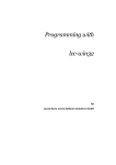
1.2
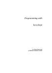
Design of the control
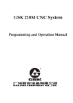
Structurally, the SINUMERIK 840C CNC can be divided into the following
three components:
SIEMENS
SINUMERIK
A
B
H
I
O
P
C
7
(
4
[
D
J
K
Q
V
R
W
8
)
5
]
9
X
:
/
"
6
?
*
’
1
2
3
!
-
^
=
0
.
E
F
G
L
M
N
S
T
U
Y
Z
% LF Al t \
i
+
M
MMC
PLC
NCK
Setpoints/actual values
for axes and spindles
Fig. 1-1
Machine control
input/output
+X
80
+C
90
-Z
100
-C
10000
[ .]
40
100
70
1
10
1000
60 70
80
90
10
+Z
100
60
-X
110
2
50
120
%
120
0
%
Structure of SINUMERIK 840C
The three components perform the following functions:
NCK
The main task of the NCK (NC kernel) is to convert the program blocks of a
part program into the traversing movements on the axes. Allowance must be
made for all the required compensating values such as tool offsets, zero offsets,
etc.
PLC
The PLC mainly performs simple control and monitoring tasks. The PLC
program must assure the smooth execution of all machine functions without
endangering man or machine.
MMC=PC
A PC has been integrated in the SINUMERIK 840C CNC for MMC (Man
Machine Communication). In addition to data management tasks, this PC
performs functions related mainly to the transfer and visualization of data
exchanged between the NCK, PLC, MMC and operator. This PC runs under
the MS-Windows operating system.
© Siemens AG 1999 All Rights Reserved
SINUMERIK 840C, OEM Version for Windows (BA)
6FC5198-6AA60-0BP1
1-3
1 Introduction - SINUMERIK 840C and its Operation
1.3
01.99
Switching the control on and off
Machine manufacturer
Switching on of the control can be implemented in various ways by the
machine manufacturer. Please refer to the machine manufacturer’s
specifications.
Switching on
the control
Please note:
The control is switched on by switching on the input voltage at the power
supply of central controller.
After the control has been switched on, different messages appear on the screen
for a few seconds. The control software is loaded, i.e. the MMC, NCK and
PLC operating system software is loaded from the hard disk onto the various
components.
The PLC user program is not loaded when the control is powered up, but is
loaded into the battery-backed RAM memory during start-up.
Power-up of the control is performed in the following sequence:
1. The operating system software is loaded
2. In the next step, the user data are transferred from the hard disk of the
MMC into the NCK memory. The machine manufacturer can configure
which individual data are to be transferred.
Both the Siemens and user cycles can be loaded in this way. A cycle disable
feature provides protection against unauthorized reading and editing of data
both in the NCK memory and on the MMC side.
The machine data (TEA1, TEA2, etc.) are not normally loaded during
power-up. These data are stored in the battery-backed static RAM of the
NCK.
3. The system now loads all of the data stored in the STANDARD workpiece.
The machine manufacturer can also configure whether the last selected
workpieces are to be loaded from the hard disk at this stage. If, in the 3rd
phase, the same data are loaded with a workpiece (e.g. RPA, TOA etc.) as
in the 2nd phase, these data are overwritten in the NCK memory by the
workpiece-related data.
If not otherwise configured by the machine manufacturer, the main menu of the
JOG mode appears after power-up of the control. Operator actions on the
control can be performed after the screen has built up completely.
6FC5198-6AA60-0BP1
1-4
© Siemens AG 1999 All Rights Reserved
SINUMERIK 840C, OEM Version for Windows (BA)
01.99
1 Introduction - SINUMERIK 840C and its Operation
Machine manufacturer
Via machine data the machine manufacturer can configure whether, after
restart of the control, the workpiece last active is to be loaded again when the
control is switched on. However, before switching off the control a workpiece
must have been loaded and selected. On restart of the control the workpieces
are loaded one after the other starting with the workpiece in channel 1 to
channel n. Generally, the STANDARD workpiece is loaded first.
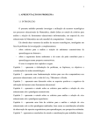
Switching off
the control
Before switching off the power supply the control must always be "powered
down" in order to assure the integrity of the file system on the hard disk and
avoid loss of data.
The control is powered down by selecting the EXIT command in the menu.
Fig. 1-2
SYSTEM DOWN query
The power supply may only be switched off when the above safety prompt has
been confirmed with "Yes" and the "SYSTEM DOWN" screen has appeared.
Important
Never switch the power supply off during normal operation. The control must
always be "powered down" by selecting the End command in the Diagnosis
menu before it is switched off.
Note
If Windows is to be closed during an active application, the system modal box
cannot be acknowledged with the NC keyboard. This is possible only with an
MF2 keyboard.
© Siemens AG 1999 All Rights Reserved
SINUMERIK 840C, OEM Version for Windows (BA)
6FC5198-6AA60-0BP1
1-5
1 Introduction - SINUMERIK 840C and its Operation
1.4
01.99
Structure of the user interface
MS-Windows
The SINUMERIK 840C is a CNC control with an MMC based on the MS
Windows operating system. You will therefore find on the screen the same
familiar elements that you have encountered when working with other MSWindows applications.
Area Switchover
The Area Switchover is the central program on the SINUMERIK 840C OEM
Version for Windows. You can use it to select 5 hierarchically organized
functional areas. The Area Switchover is activated by the following key:
Fig. 1-3
Area Switchover
You can subsequently open the individual menus by selecting the items on the
menu or softkey bars and activate the various user areas from there.
6FC5198-6AA60-0BP1
1-6
© Siemens AG 1999 All Rights Reserved
SINUMERIK 840C, OEM Version for Windows (BA)
01.99
1.5
1 Introduction - SINUMERIK 840C and its Operation
NCK and MMC areas
Most of the individual user areas on the SINUMERIK 840C are in two main
groups:
• NCK areas
• MMC areas
The operating principle differs slightly for each of the groups. While the
SYSTEM 800 operating principle is used in the NCK, the user interface in the
MMC areas is oriented to the MS-Windows operating system.
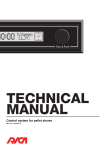
NCK areas
The NC screen contains "machine displays" which present the user with
information communicated from the NCK or PLC. Reciprocally, all keyboard
input on the operator panel is relayed to the NCK or PLC.
The selection of an NCK area is indicated by the appearance of the mode in the
display.
Fig. 1-4
NCK area: Machine
© Siemens AG 1999 All Rights Reserved
SINUMERIK 840C, OEM Version for Windows (BA)
6FC5198-6AA60-0BP1
1-7
1 Introduction - SINUMERIK 840C and its Operation
01.99
The following list provides an overview of all the NCK areas:
• Machine
• Parameters
• Programming
-
Edit NC
• Diagnosis
-
PLC Status
-
NC Service
-
NC/PLC Startup
-
Machine Data
• Information
Softkeys
NC Information
Within the NCK areas you will find a hierarchical menu structure operated
exclusively using softkeys.
The softkeys are located below the screen. Various functions are assigned to
the softkeys. The function performed when the key is pressed is displayed in
the softkey bar.
Fig. 1-5
Operating structure in NCK areas
6FC5198-6AA60-0BP1
1-8
© Siemens AG 1999 All Rights Reserved
SINUMERIK 840C, OEM Version for Windows (BA)
01.99
1 Introduction - SINUMERIK 840C and its Operation
Operating the RECALL key brings you back to the next higher menu level.
A red arrow in the extreme left softkey window indicates a return to the next
higher level:
With the ETC key, you can expand the softkey menu if an extension is
available.
If there is an arrow in the 7th softkey window (on the right),
this key is active.
You can press the Machine Area key to change directly from any area to the
Machine area.
M
Menu storage
+
A menu storage function has also been implemented in the NCK areas. The last
active menu of any NCK area (e.g. R parameter display) is automatically
saved.
If you then select a different NCK area (e.g. Machine), you can use the key
combination illustrated on the left to return to the same point in the starting
menu (R parameter display).
© Siemens AG 1999 All Rights Reserved
SINUMERIK 840C, OEM Version for Windows (BA)
6FC5198-6AA60-0BP1
1-9
1 Introduction - SINUMERIK 840C and its Operation
01.99
MMC areas
These areas provide the user with information on data in the MMC. The mode
is not displayed in the MMC areas.
MS-Windows
The user interface in these areas of the SINUMERIK 840C is based on MSWINDOWS. You will probably be familiar with the windowing technology
used here.
In MS-Windows, there is a separate window for each MMC area. If another
MMC area is selected, the original window is overlaid.
Task manager
You can use the task manager to switch between the different MMC areas
(windows). If you call an MMC area that you have already deselected, the last
display for that area is automatically displayed again. Menu storage as featured
in the NCK area is therefore not necessary.
You can call the task manager using the "Page" keys in Area Switchover.
or
Fig. 1-6
Area switchover with active task manager
With SINUMERIK 840C OEM Version for Windows, the applications can be
controlled using both the standard MS-WINDOWS operating elements and
softkeys.
6FC5198-6AA60-0BP1
1-10
© Siemens AG 1999 All Rights Reserved
SINUMERIK 840C, OEM Version for Windows (BA)
01.99
1.6
1 Introduction - SINUMERIK 840C and its Operation
Data management
The SINUMERIK 840C user interface also provides its own data manager with
integrated editor.
Fig. 1-7
NC Data Management
The Data Management area can be used as a convenient and efficient means
of managing and editing the data on the hard disk. The following functions can
also be performed:
• Transfer of data between the NCK and MMC
• Transfer of data between the MMC and a peripheral device.
Directories
To help the user keep track of the large volumes of data stored on the hard
disk, files are organized into "directories". A directory is similar to a file binder
in a filing cabinet. All of the data belonging to a particular project are stored in
the same directory.
Workpieces
Similarly, the SINUMERIK 840C OEM Version for Windows allows all of the
data belonging to a particular workpiece to be stored in a separate directory.
This type of directory is referred to here as a workpiece.
The main advantage of workpiece-oriented data management is the ability to
transfer all of the data required for a workpiece from the hard disk to the NCK
or peripheral device with a single operator action.
© Siemens AG 1999 All Rights Reserved
SINUMERIK 840C, OEM Version for Windows (BA)
6FC5198-6AA60-0BP1
1-11
1 Introduction - SINUMERIK 840C and its Operation
1.7
01.99
File manager and control panel
The File Manager and the Control Panel of MS-WINDOWS are available on
the SINUMERIK 840C for global file manipulation and system settings within
the MMC areas.
Fig. 1-8
MS-WINDOWS Control Panel
The Control Panel is used particularly for the following settings:
• Screen colors
• Time
• Installation and configuration of a printer
The File Manager and Control Panel can be selected from the Diagnosis
menu in the Area Switchover.
Selection of these menu items is password-protected as standard.
6FC5198-6AA60-0BP1
1-12
© Siemens AG 1999 All Rights Reserved
SINUMERIK 840C, OEM Version for Windows (BA)
01.99
1.8
1 Introduction - SINUMERIK 840C and its Operation
Data backup
Note
The SINUMERIK 840C allows the storage of large volumes of data on the
hard disk. Siemens recommends you strongly to keep a copy of all relevant
data on an external data device (such as a programming unit or PC, etc.), as
the data can be irrecoverably lost in the event of a hard disk failure.
1.8.1
RS-232C (V.24) output
You can use the RS-232C (V.24)/20mA interface on the MMC CPU to output
your user data from the hard disk in binary or punchtape format. The interface
switches automatically RS-232C (V.24) between and 20mA mode according to
the connected device and cable used.
1.8.2
Data management/PCIN
The output of NCK data in punchtape format is performed using the data
manager. Other user data can be input or output in binary format with the aid of
the PCIN data backup program.
1.8.3
VALITEK streamer
A complete copy of all the data on the hard disk can also be made using the
VALITEK streamer. The Valitek streamer is connected to the parallel
interface.
Important
Remember to make regular backups of your data so that you have a recent
copy of data which you can reload onto the control in the event of an error.
You can print your data on a printer connected to the parallel interface.
The FD-E2 diskette drive can also be used for data backup (optional).
© Siemens AG 1999 All Rights Reserved
SINUMERIK 840C, OEM Version for Windows (BA)
6FC5198-6AA60-0BP1
1-13
1 Introduction - SINUMERIK 840C and its Operation
1.8.4
01.99
CD-ROM access via PC link software (SW 6 and higher)
PC link
Data can be stored on an external PC by using the user interface "PC link".
Installation
procedure
In software version 6 and higher, it is possible to update the software via a PC
link. The software is delivered on a CD.
1. Install the PC link on the external PC by using the "install.bat" file.
2. Connect the control to the external PC by means of a parallel cable.
Note
The PC link connection required for the installation and start-up has not been
EMC tested as required for normal operation, and may therefore only be used
for servicing purposes (parallel transfer cable,
Order No. 6FX2 002-1AA02-1AD0).
3. The following installation procedure is described in the "readme.txt" file in
the root directory of the CD.
Note
Before initiating backup or restore on the external PC, you have to select the
correct menu item on the control (Backup or Restore).
Important
The menu options of the PC Link program on the external PC are activated on
the control depending on the type of selection (Backup, Restore, Install or
Free Data Transfer).
6FC5198-6AA60-0BP1
1-14
© Siemens AG 1999 All Rights Reserved
SINUMERIK 840C, OEM Version for Windows (BA)
01.99
1.8.5
1 Introduction - SINUMERIK 840C and its Operation
Computer link
Communications modules are optionally available for setting up a computer
link in the NCK area of the SINUMERIK 840C.
The machine manufacturer can also implement his or her own computer link.
The SINUMERIK 840C offers the following components for networking:
• Standard PC network cards. These can be plugged into the "AT box"
(central unit).
• Pocket network adapters. These connect a PC to the network via the
parallel interface.
Please refer to the machine manufacturer’s description for further information.
© Siemens AG 1999 All Rights Reserved
SINUMERIK 840C, OEM Version for Windows (BA)
6FC5198-6AA60-0BP1
1-15
1 Introduction - SINUMERIK 840C and its Operation
1.9
01.99
Online help
The SINUMERIK 840C allows users to call up help screens for fast
information in relation to a task, function or command.
NCK areas
i
The following features are provided for calling up help displays in these areas:
• With this key you activate a help display for a special operation.
The possibility is indicated by the "i" in the 1st (left) softkey.
Press RECALL to deselect this help screen.
Fig. 1-9
Online help display in the machine area
6FC5198-6AA60-0BP1
1-16
© Siemens AG 1999 All Rights Reserved
SINUMERIK 840C, OEM Version for Windows (BA)
01.99
Alarm/
message window
1 Introduction - SINUMERIK 840C and its Operation
In this window, the help information is based on the MS-Windows help system.
Fig. 1-10 Online help in the alarm window
• First select Alarm Window from the Diagnosis menu and position the
selection bar on the desired alarm.
Press this key to display an MS-WINDOWS help window containing
additional information relating to queries, causes and remedies. Use the
ARROW keys to scroll within the help window. ■
© Siemens AG 1999 All Rights Reserved
SINUMERIK 840C, OEM Version for Windows (BA)
6FC5198-6AA60-0BP1
1-17
1 Introduction - SINUMERIK 840C and its Operation
6FC5198-6AA60-0BP1
1-18
01.99
© Siemens AG 1999 All Rights Reserved
SINUMERIK 840C, OEM Version for Windows (BA)
2
Operator Interface
2.1 Operator panel ............................................................................................................2-2
2.2 Operating elements.....................................................................................................2-3
2.2.1 Operator panel .........................................................................................................2-3
2.2.2 Full PC keyboard/MF2 keyboard..............................................................................2-5
2.2.3 Operating elements of the operator panel keyboard/full keyboard ..........................2-7
2.2.4 The operating elements of the machine control panel...........................................2-13
2.2.5 Operating elements of the hand-held unit (HHU, A-MPC).....................................2-23
2.2.6 Screen layout .........................................................................................................2-24
© Siemens AG 1999 All Rights Reserved
SINUMERIK 840C, OEM Version for Windows (BA)
6FC5198-6AA60-0BP1
2-1
2 Operator Interface
2.1
01.99
Operator panel
Different operator panels can be connected to the SINUMERIK 840C. The
following components can be added: machine control panel, hand-held unit and
PC standard keyboard (MF-2).
• 19" operating panel with 14" colour monitor
(2x7 softkeys, switchover keys)
• 19" NC full keyboard
(alphabetic group of keys, numeric group of keys, cursor group of keys)
• 19" slimline operator panel with 9.5" monochrome LC display including
NC full keyboard
(2x7 softkeys, switchover keys, alphabetic group of keys, numeric group of
keys, cursor group of keys)
• 19" slimline operator panel with 10" or 9.5" TFT colour LC display
including NC full keyboard
(2x7 softkeys, switchover keys, alphabetic group of keys, numeric group of
keys, cursor group of keys)
• PC standard keyboard (MF-2)
• 19" machine control panel, M version
• 19" machine control panel, T version
• Hand-held unit
6FC5198-6AA60-0BP1
2-2
© Siemens AG 1999 All Rights Reserved
SINUMERIK 840C, OEM Version for Windows (BA)
01.99
2 Operator Interface
2.2
Operating elements
2.2.1
Operator panel
M
A
H
O
A
Fig. 2-1
B
I
C
J
D
K
E
L
F
M
P
Q
R
S
T
V
W
X
Y
Z
G
N
U
7
4
(
[
1
=
8
5
)
]
2
@
B
0
9
6
3
;
.
:
?
!
+/-
C
/
*
+
"
%LF
ALT
\
i
’
^
,
D
19" operator panel with 14" colour monitor (no longer available)
© Siemens AG 1999 All Rights Reserved
SINUMERIK 840C, OEM Version for Windows (BA)
6FC5198-6AA60-0BP1
2-3
2 Operator Interface
01.99
SIEMENS
SINUMERIK
A
B
C
D
E
F
G
H
I
J
K
L
M
N
O
P
Q
R
S
T
U
V
W
X
Y
Z
7
(
8
)
9
:
/
"
4
[
5
]
6
?
*
’
3
!
-
^
.
+/-
+
,
1
=
2
@
0
;
%LF Alt
\
i
M
A
Fig. 2-2
B
C
D
SINUMERIK 9.5"/10" slimline operator panel
A: 14"/10"/9.5 colour graphics monitor
14 softkeys
ETC key, Recall key
Machine area key
Area switchover key
B: Alphabetic group of keys
C: Numeric group of keys with editing and input keys
D: Cursor group of keys with control keyboard
6FC5198-6AA60-0BP1
2-4
© Siemens AG 1999 All Rights Reserved
SINUMERIK 840C, OEM Version for Windows (BA)
01.99
2.2.2
2 Operator Interface
Full PC keyboard/MF2 keyboard
Full keyboard
A standard MF2 keyboard (full keyboard) can be connected to the operator
panel interface.
A set of key caps is supplied with this standard full keyboard. These key caps
correspond to the symbols on the operating panel and can be mounted on the
standard full keyboard as shown in Fig. 2.3.
The functions of the machine control cannot be implemented on the MF2
keyboard.
MF2 keyboard
An MF2 keyboard (American keyboard) can be connected directly to the
keyboard input on the MMC module. The following restriction applies to this
configuration.
Note
When connected directly to the MMC module, the MF2 keyboard does not
comply with the requirements of a SINUMERIK control with respect to noise
immunity. The MF2 keyboard may therefore only be used for start-up and
servicing.
© Siemens AG 1999 All Rights Reserved
SINUMERIK 840C, OEM Version for Windows (BA)
6FC5198-6AA60-0BP1
2-5
2 Operator Interface
Fig. 2-3
01.99
Full keyboard
6FC5198-6AA60-0BP1
2-6
© Siemens AG 1999 All Rights Reserved
SINUMERIK 840C, OEM Version for Windows (BA)
01.99
2 Operator Interface
2.2.3
Operating elements of the operator panel keyboard/full keyboard
Softkey: Key which is assigned a variable function or menu via a menu bar on
the screen.
F1
Horizontal softkey bar (full keyboard): standard applications on the
SINUMERIK 840C are operated exclusively using the horizontal softkeys.
F7
F3
F9
+
Shift
F1
F7
F3
Vertical softkey bar (full keyboard): The designation SK1 to SK7 corresponds
to the designation on the additional key caps of the standard keyboard (see also
the illustration of the full keyboard). The vertical softkeys are not used in the
standard version and are therefore not displayed.
F9
MACHINE AREA key. Press this key to switch from any user area to the
Machine area.
M
RECALL key: Return to the higher level menu
ETC key: Extension of the softkey bar in the same menu
DATA AREA key: the Area Switchover is selected (or deselected if it is
already selected) by pressing this key. When selected, the Area Switchover is
displayed for the currently active application.
SHIFT key: Switching over keys with double allocation; not self-retaining, i.e.
two keys must be activated.
+
With the combination SHIFT + DATA AREA, an NCK menu can be
reselected if it was deselected by another NCK application. It is thus possible
to move from an NCK menu (e.g. R parameter display) to a different
application in the NCK area (e.g. Machine) and then to return to the same point
in the parameter display.
© Siemens AG 1999 All Rights Reserved
SINUMERIK 840C, OEM Version for Windows (BA)
6FC5198-6AA60-0BP1
2-7
2 Operator Interface
01.99
Lower case letter a ... z, activated with SHIFT
Upper case letter A ... Z
Underscore
SPACE, blank
Press the SPACE key to select the checkbox in a dialog box.
Special character: less than
Digit 1
Special character: greater than
Digit 2
Exclamation mark
Digit 3
Square bracket
Digit 4
Square bracket
Digit 5
Question mark
Digit 6
Round bracket
Digit 7
Round bracket
Digit 8
Colon
Digit 9
Semicolon
Digit 0
Inverted commas
Oblique stroke, division
6FC5198-6AA60-0BP1
2-8
© Siemens AG 1999 All Rights Reserved
SINUMERIK 840C, OEM Version for Windows (BA)
01.99
2 Operator Interface
Apostrophe
Multiplication
Special character
Hyphen, subtraction
Special character
Equal sign
Comma
Plus, addition
.
Change of sign
Fullstop (point/period)
+/or
Sh ift
+
or
+
CLEAR key: deletes the character to the left of the input cursor. Identical
to the <BACKSPACE> key on the MF2 keyboard.
Backspace
CANCEL key: deletes the character underneath the input cursor. Identical
to the <DELETE> key on the MF2 keyboard.
or
EDIT key for editing words in the NCK areas. The EDIT key can be used
in the dialog boxes of the MMC areas to jump from one input box to the next.
Identical to the <TABULATOR> key on the MF2 keyboard.
Tab ulator
or
INPUT key: confirm input (save the edited value to memory). Identical
to the <ENTER> key on the MF2 keyboard.
E n te r
© Siemens AG 1999 All Rights Reserved
SINUMERIK 840C, OEM Version for Windows (BA)
6FC5198-6AA60-0BP1
2-9
2 Operator Interface
01.99
LINE FEED key: identifier for end of block
Percent sign; identifier for beginning of main program
ALT/BACKSLASH key: this key is used for the selection of menus and dialog
boxes in MS-WINDOWS. It is located to the right of the LINE FEED/percent
sign key. It is not labelled in standard versions.
The ALT key is used for the selection of MMC menus and dialog boxes. When
used in combination with the SHIFT key, it generates the "\" (backslash)
character. This is useful for entering complete file paths in MMC applications.
Help
i
or
Sh ift
+
L
F1
M
HELP key: this key can be used in machine displays to call up explanations
and information on the current operating state.
Pressing it a second time brings you back to the previous display. The "i" in the
softkey bar indicates the possibility of calling up information by pressing the
"Help" key.
You can press the HELP key in the alarm window to call up an explanation of
the active alarm.
Actual position in large
characters
When you operate this key, the screen display of "Actual position" is shown in
double-height characters.
Operating the key again brings you back to the previous full display (with
standard size characters).
or
Sh ift
+
F11
or
or
PgUp
PgDn
PAGE UP key: press these keys to scroll the screen one page back.
When the Area Switchover is active, the MS-WINDOWS Task Manager is
selected. You can press PAGE UP and PAGE DOWN to select the desired
application and press any other key to bring it into the foreground.
PAGE DOWN key: you "page" down by one display. In a part program you
can page down the display (towards the end of the program), or up (towards the
beginning of the program).
When the Area Switchover is active, this key activates the MS-Windows Task
Manager. You can choose an application by pressing the PAGE UP and PAGE
DOWN keys and bring it into the foreground by subsequently pressing any
other key.
6FC5198-6AA60-0BP1
2-10
© Siemens AG 1999 All Rights Reserved
SINUMERIK 840C, OEM Version for Windows (BA)
01.99
2 Operator Interface
ARROW keys: with these keys, you move the cursor on the screen to the left or
to the right, upwards (back) or downwards (forward).
With the ARROW keys, you can move the cursor in the input fields (toggle
fields, etc.) or in the various editors (WEdit editor; DIN editor). Further
information is given in the respective Sections of this Operator’s Guide.
or
or
Home
End
HOME key: moves the cursor to the beginning of the line in the WEdit editor.
This key is used within a machine display to advance the input field..
END key: moves the cursor to the end of the line in the WEdit editor.
This key is used within a machine display to activate/deactivate the cursor in
the input line.
With this key you activate the cursor in the input line (NCK only), move it by
means of the cursor keys, in order to correct or insert. When operating the key
again, you deactivate the cursor.
SELECTION/SEARCH key
Select toggle fields in machine displays and text in the FlexOS editor/Search
text.
SHIFT + SELECTION
(reset a toggle field in a machine display)
Acknowledge alarm
or
ESC
ACKNOWLEDGE ALARM: press this key in the alarm window or when the
Machine area is selected to acknowledge the information from the NC
monitoring system displayed in the alarm line such as:
• Alarm number and alarm text for CANCEL alarms
• The machine manufacturer can configure whether this key is to act on all
channel-specific CANCEL alarms or only on the CANCEL alarms of the
current channel.
In MMC applications, the key has the same function as the ESC key on the
MF2 keyboard.
Change of mode groups
Channel switchover
© Siemens AG 1999 All Rights Reserved
SINUMERIK 840C, OEM Version for Windows (BA)
6FC5198-6AA60-0BP1
2-11
2 Operator Interface
Changing mode
groups
01.99
The NC channels are grouped together in mode groups. With the SINUMERIK
840C up to 2 mode groups can be selected.
Machine manufacturer
Please note:
The channels are assigned to mode groups by the machine manufacturer!
Channel switchover
• Pressing this key once switches to the next higher channel number, referred
to the number displayed in the channel status field.
• Pressing the key again switches on to the next
channel or back.
• The channel can be selected directly by entering the channel number and
then operating the key.
• The NC area of the SINUMERIK 840C is divided into a maximum of six
channels.
6FC5198-6AA60-0BP1
2-12
© Siemens AG 1999 All Rights Reserved
SINUMERIK 840C, OEM Version for Windows (BA)
01.99
2.2.4
2 Operator Interface
The operating elements of the machine control panel
Machine control panel
for a milling machine
X
Y
80
Z
90
[.]
1
4
5
40
100
70
6
100
7
8
110
90
100
110
2
9
120
0
120
50
1000
80
6
60
10
60 70
20
10
%
%
10000
+
-
Machine control panel
for a turning machine
+X
+C
80
100
70
[. ]
1
-Z
40
90
+Z
110
100
-C
-X
120
50
1000
Fig. 2-4
%
10000
80
90
100
6
60
10
60 70
20
10
110
2
120
0
%
Machine control panels
Machine tool operations such as traversing of the axes or program start can
only be triggered via a machine control panel.
The machine tool can be equipped with a standard Siemens machine control
panel or with a special machine control panel from the machine tool
manufacturer.
A maximum of two mode groups is possible.
The standard Siemens machine control panel is described. Should another
machine control panel be used, please refer to the Operator’s Guide of the
machine tool manufacturer.
© Siemens AG 1999 All Rights Reserved
SINUMERIK 840C, OEM Version for Windows (BA)
6FC5198-6AA60-0BP1
2-13
2 Operator Interface
01.99
The standard SIEMENS machine control panel has the following operating
elements:
• Emergency stop button
• Operating modes with function keys
• Spindle control
• Feed control
• Direction keys with rapid override
• Keyswitch
• Reset key
• Program control
Emergency stop
button
You operate the red button in emergency situations:
• When human life is in danger
• When there is a risk of the machine or workpiece being damaged.
Operation of the "Emergency stop" button generally brings all drives to a stop
with maximum braking torque.
Machine manufacturer
For further or other reactions to "Emergency stop", refer to the machine tool
manufacturer’s documentation.
6FC5198-6AA60-0BP1
2-14
© Siemens AG 1999 All Rights Reserved
SINUMERIK 840C, OEM Version for Windows (BA)
01.99
2 Operator Interface
Operating modes
Table 2-1
Overview - Operating modes
Key symbol
Definition
Designation of operating mode
The axes are traversed
continuously in JOG mode using
the direction keys or
incrementally using the direction
keys or the handwheel.
JOG
Set-up
(Jogging)
Interactive creation of programs
TEACH IN
The machine is controlled by
executing a block or a series of
blocks. The operator panel is
used to input blocks.
MDA
Manual Data Automatic
The machine is controlled by
automatic execution of programs.
AUTOMATIC
If a mode key is pressed, the corresponding mode is selected and previously
selected modes and functions are cancelled.
The active mode is indicated and confirmed by the associated LED.
REPOS and
reference point
Table 2-2
REPOS - Reference point
Key symbol
Definition
Designation of function
Repositioning, approach contour
again in JOG/TEACH IN mode
REPOS
Reposition
Approach reference point in JOG
mode
REFPOINT
Approach reference point
The REPOS function is only active in JOG and TEACH IN mode and can be
selected only in these modes.
The active function is indicated by the associated LED lighting up.
The function can be cancelled by pressing the function key again. The function
is also cancelled if you change the operating mode.
© Siemens AG 1999 All Rights Reserved
SINUMERIK 840C, OEM Version for Windows (BA)
6FC5198-6AA60-0BP1
2-15
2 Operator Interface
01.99
INC function
Table 2-3
Overview - Submode INC
Key symbol
Definition
Designation of function
Increment mode with variable
step size (setting data).
INC VAR
Increment mode with fixed step
size of 1 increment
INC
Incremental Feed
Incremental Feed variable
Increment mode with fixed step
size of 10 increments
Increment mode with fixed step
size of 100 increments.
Increment mode with fixed step
size of 1000 increments.
Increment mode with fixed step
size of 10 000 increments.
The increment size depends on the display resolution that has been set.
The INC functions can be activated in conjunction with the following modes:
• JOG mode
• TEACH IN mode
Spindle override
switch
• The rotary switch with 16 notched positions enables you to reduce or
increase the programmed spindle speed S (corresponds to 100%).
• A machine data determines whether the spindle override switch is active,
i.e. it is determined by the machine manufacturer.
• The set spindle speed value S is displayed as an absolute value in % on the
screen.
Control:
50% to 120% of the programmed spindle speed
Step size:
5% from position to position
Machine manufacturer
The given step size and the control range are valid for standard machine data
(MD). These can be altered by the machine tool manufacturer to suit a specific
application!
6FC5198-6AA60-0BP1
2-16
© Siemens AG 1999 All Rights Reserved
SINUMERIK 840C, OEM Version for Windows (BA)
01.99
Spindle stop
2 Operator Interface
When you press the SPINDLE STOP key:
• The spindle speed is reduced down to zero
• The associated LED lights up as soon as SPINDLE STOP is accepted by
the control, for example also with M05 (see Programming Guide).
Example for use of SPINDLE STOP
• To effect tool change
• To enter S, T, H, M functions while setting up (overstoring)
Spindle start
When you press the "Spindle start" key:
• The spindle is enabled. If the spindle has been stopped with SPINDLE
STOP in a program it can be started again with SPINDLE START.
• The associated LED lights up as soon as "Spindle start" is accepted by the
control.
Machine manufacturer
The following is defined in the machine data or setting data:
- Max. spindle speed
- Values for the spindle speed override
(see machine-tool manufacturer’s instructions)
Feedrate control
Feedrate/rapid override
The rotary switch with 23 notched positions allows you to reduce or increase
the programmed feedrate value F (corresponds to 100%).
The set feedrate value F is indicated on the screen in %.
Setting range:
0% to 120% of the programmed feedrate.
The 100% value is not exceeded in rapid traverse.
Step size:
0%, 1%, 2%, 4%, 6%, 8%, 10%, 20%, 30%, 40%, 50%,
60%, 70%, 75%, 80%, 85%, 90%, 95%, 100%, 105%,
110%, 115%, 120%
© Siemens AG 1999 All Rights Reserved
SINUMERIK 840C, OEM Version for Windows (BA)
6FC5198-6AA60-0BP1
2-17
2 Operator Interface
01.99
Machine manufacturer
The given increment sizes and the control range are valid for standard machine
data (MD). These can be altered by the machine-tool manufacturer to suit a
specific application.
Feed hold
When you operate the FEED HOLD key:
• The program being executed is stopped
• The feed drives are brought to a controlled stop
• The associated LED lights up as soon as FEED HOLD is accepted by the
control.
Examples for use of FEED HOLD:
• During application in MDA mode, a block with a fault is discovered
• To effect tool change
Feed start
When you operate the FEED START key:
• The part program continues in the current block
• The feedrate is increased to the value specified by the program
• The associated LED lights up as soon as FEED START is accepted by the
control.
Machine manufacturer
The following is configured by the machine manufacturer:
• The feed and rapid traverse rates
• The values for feed override positions
• Whether the feed override switch is also active for rapid traverse
• The axis names (see machine-tool manufacturer’s specifications)
6FC5198-6AA60-0BP1
2-18
© Siemens AG 1999 All Rights Reserved
SINUMERIK 840C, OEM Version for Windows (BA)
01.99
2 Operator Interface
Direction keys,
turning machine
You traverse the axis marked X.
You traverse the axis marked Z.
You traverse the axis marked C.
Rapid traverse
overlay
When you operate this key at the same time as any of the keys above, the axis
is traversed in rapid traverse mode
Direction keys,
milling machine
You select the axis marked X, Y, Z etc.
You traverse the selected axis in positive or in negative direction.
You traverse other assigned axes in the same way.
If an INC function has been set and the direction key is pressed (whether for a
long or a short time), the axis traverses by only one step (1/10/100/1000/10000
increments depending on the setting).
If an INC function is not selected, the default setting continuous is active. The
axis traverses as long as the direction key is pressed.
Please take into consideration that when the safety interlocks are enabled only
the simple traverse movement via the JOG keys or via the handwheel is
permitted.
© Siemens AG 1999 All Rights Reserved
SINUMERIK 840C, OEM Version for Windows (BA)
6FC5198-6AA60-0BP1
2-19
2 Operator Interface
01.99
Rapid traverse
overlay
When you operate this key at the same time as any of the keys above, the axis
is traversed in rapid traverse mode.
Keyswitch
The SINUMERIK 840C keyswitch has 4 positions which are evaluated by the
control’s operating system. Three keys of different colours belong to the
keyswitch and these can be turned and removed from the following positions:
Table 2-4
Position of switch
Withdraw position
-
Function
Data is only displayed
Position 0
0 + 1 key 1
black
Generate, edit and delete workpiece
data
0 + 1 + 2 key 2
green
Generate, edit and delete interface data
and setting data
0+1+2+3 key 3
red
The STANDARD workpiece is not
loaded when the control is powered
up. Use only for start-up and servicing!
Position 1
Position 2
Position 3
Machine manufacturer
The key positions can be assigned with additional functions by the machine
manufacturer. Please read the machine manufacturer’s Operator’s Guide.
Note
If the PLC is in the STOP state the input display on the machine control panel
is not scanned. In this case the control can be powered up via keyswitch
position 3.
6FC5198-6AA60-0BP1
2-20
© Siemens AG 1999 All Rights Reserved
SINUMERIK 840C, OEM Version for Windows (BA)
01.99
2 Operator Interface
Reset key
When you operate the "Reset" key:
• Execution of the current part program is interrupted, if the key releases a
mode group reset (= reset of all channels).
• Messages are cleared from the monitoring system unless they are POWER
ON or acknowledgement alarms.
• The control is switched to the "Reset" state, i.e.
− The NC control remains synchronized with the machine.
− All buffer and user memories are cleared (but the contents of the part
program memory are retained).
− The control is in the Reset state and ready for a new program run.
Machine manufacturer
The machine manufacturer can configure the RESET key such that it acts on
channel/mode group or on the whole NC.
Single block
This function allows you to execute a part program on a block-by-block basis.
The "Single block" function can be activated in the AUTOMATIC, TEACH IN
and MDA modes.
When SINGLE BLOCK operation is active:
• The SBL (Single Block) message is shown on the CRT display,
• The current block of the part program is executed only when you press the
"NC start" key,
• When the current block has been executed, processing is stopped,
• The following block can be executed by pressing the "NC start" key again.
The function does not work with calculation blocks. Calculation blocks are part
program blocks which execute programmed calculations (R parameters
calculation operations), but do not output anything to the machine or to the
PLC.
If SINGLE BLOCK is activated, the corresponding LED lights up on the
machine control panel.
The function can be deselected by pressing the key again.
© Siemens AG 1999 All Rights Reserved
SINUMERIK 840C, OEM Version for Windows (BA)
6FC5198-6AA60-0BP1
2-21
2 Operator Interface
01.99
NC Stop
If you press the NC STOP key, processing of the current part program is
interrupted. All axis movements are brought to a controlled stop. The reactions
of the H and M functions in the case of NC STOP are configured by the
machine manufacturer. For more information refer to the machine
manufacturer’s documentation. The associated LED lights up.
Processing can then be continued by pressing NC START.
NC Start
If you press the NC START key, the part program called is started at the
current block; the associated LED lights up. Processing of a part program
interrupted with NC STOP is continued at the point of interruption on pressing
NC START.
Caution
The axis positions programmed in the current block are approached with linear
interpolation after the "NC START" key has been activated. Collision danger!
6FC5198-6AA60-0BP1
2-22
© Siemens AG 1999 All Rights Reserved
SINUMERIK 840C, OEM Version for Windows (BA)
01.99
2.2.5
2 Operator Interface
Operating elements of the hand-held unit (HHU, A-MPC)
Machine manufacturer
The display and key functions can be configured by the machine manufacturer.
For further details refer to the machine manufacturer’s documentation.
1
SIEMENS
2
3
40
30
20
10
50
60
70
80
4
90
110100
5
6
Fig. 2-5
Meaning of the
operating
elements:
Operating elements of the hand-held unit (HHU)
1 - EMERGENCY STOP switch
2 - Two-line display
3 - Group of keys with LEDs
4 - Feed/rapid traverse/override switch
5 - Keyswitch
6 - Handwheel
© Siemens AG 1999 All Rights Reserved
SINUMERIK 840C, OEM Version for Windows (BA)
6FC5198-6AA60-0BP1
2-23
2 Operator Interface
2.2.6
01.99
Screen layout
1
2
3
4
Application
area
5
Fig. 2-6
Screen layout
1 - Application title bar
2 - Message line
3 - Alarm line
4 - Time display, general channel status display with icons
5 - Softkeys
The display is divided into various window areas. An alarm line and a message
line are displayed at the top left-hand side of the screen. To the right of this
area is a box displaying the current time and the icons.
The application window starts below the alarm area and extends to the softkey
bar. Standard Siemens applications are operated using the horizontal softkeys.
The vertical softkeys are not used and are therefore not displayed. ■
6FC5198-6AA60-0BP1
2-24
© Siemens AG 1999 All Rights Reserved
SINUMERIK 840C, OEM Version for Windows (BA)
3
MMC Applications
3.1
Introduction........................................................................................................3-2
3.2
Components of an MS-Windows window ..........................................................3-4
3.3
Operations with windows...................................................................................3-6
3.4
Working with menus ..........................................................................................3-8
3.5
Working with dialog boxes...............................................................................3-10
© Siemens AG 1999 All Rights Reserved
SINUMERIK 840C, OEM Version for Windows (BA)
6FC5198-6AA60-0BP1
3-1
3 MMC Applications
3.1
01.99
Introduction
Before you start working with the SINUMERIK 840C you should be familiar
with some of the basic elements of MS-WINDOWS and its operation.
The control can be operated using 3 different keyboards. The operator panel
keyboard and an MF2 keyboard (full keyboard) can be connected to the
keyboard interface or the slimline operator panel. The operator panel interface
is connected to the 1st serial interface of the MMC module via an RS 232C
(V.24) cable.
A conventional MF2 keyboard can also be connected directly to the keyboard
input of the MMC central unit. For reasons of noise immunity, this version may
not be used for normal operation, but is intended exclusively for start-up and
servicing.
When several keyboards are used together, the user should check that the
<SHIFTLOCK>, <CAPSLOCK> and <ALT> keys work on all of the
keyboards.
The MF2 keyboard connected to the central unit allows the operation of MSWindows applications exactly as described in the Microsoft documentation.
The SINUMERIK 840C is operated as standard with the operator panel
keyboard.
Aside from the usual key assignments for operation in the Machine area,
certain keys have been redefined for MS-WINDOWS applications. In
particular, key combinations such as <ALT> + <HOTKEY> have the same
effect as on the MF2 keyboard. On the operator panel keyboard, however, the
two keys must be pressed consecutively (and not simultaneously).
Machine manufacturer
In the new firmware version of the operator panel interface module it is
possible to evaluate any key actuation on the operator panel or full keyboard
connected to this in a similar way as an MF2 keyboard connected to the
central unit.
Combined key inputs such as ALT + X are thus possible.
In addition , the machine manufacturer is able to plan the key allocation of the
operator panel freely.
Please refer to the machine manufacturer’s documentation.
The following section describes some of the basic elements of MS-Windows
and the operation of MMC applications using the operator panel keyboard.
6FC5198-6AA60-0BP1
3-2
© Siemens AG 1999 All Rights Reserved
SINUMERIK 840C, OEM Version for Windows (BA)
01.99
3 MMC Applications
Operator panel
keyboard
In the following section, references to the keys on the operator panel keyboard
are made in UPPER CASE CHARACTERS (e.g. CANCEL, ALT, EDIT, etc.).
MF2 keyboard
The keys on the MF2 keyboard are also enclosed in angle brackets (e.g.
<ALT>, <ESC>, etc.).
Language
In general, all menus and dialog boxes, including those that directly access
MS-WINDOWS resources, appear in the selected language. The language can
be installed at the time of start-up and then selected in the diagnostics menu.
The following languages are available as standard:
English, French, German, Spanish and Italian. Further languages available
are Swedish, Portuguese and Czech.
Important
If an application crashes, it can generally only be operated using the MF2
keyboard of the central unit and not the operator panel keyboard.
If no MF2 keyboard is provided, the control must be switched off and
powered up again.
© Siemens AG 1999 All Rights Reserved
SINUMERIK 840C, OEM Version for Windows (BA)
6FC5198-6AA60-0BP1
3-3
3 MMC Applications
3.2
01.99
Components of an MS-Windows window
In MS-WINDOWS, you work with rectangular screen areas known as
windows. All windows have certain standard elements such as a title bar and
menus.
The following figure depicting an MS-Windows editor illustrates the major
components of a window.
Control menu bar
Title bar
Window title
Minimize
Maximize
Menu bar
Horizontal scroll bar
Fig. 3-1
Vertical scroll bar
Components of a window in MS-Windows
Title bar
The title bar shows the name of the application program or the document to be
edited. If several windows are open simultaneously, the title bar of the active
window is displayed in a different colour or with a different intensity to all the
other windows.
Menu bar
The menu bar displays the menus available in this application.
Scroll bars
The scroll bars show you the position of the currently displayed window pane
in documents of more than one page in length.
Window border
The window border represents the outer limit of a window.
6FC5198-6AA60-0BP1
3-4
© Siemens AG 1999 All Rights Reserved
SINUMERIK 840C, OEM Version for Windows (BA)
01.99
3 MMC Applications
Note
Standard Siemens applications have no control menu and no minimize/
maximize buttons. The size and position of an application can therefore only
be altered by the machine manufacturer, not the user.
The windows in standard MS-Windows applications such as the File Manager
or Control Panel also contain further elements.
Control menu box
The control menu box of an application program is located in the top left-hand
corner and can be opened by pressing the ALT and SPACE key combination or
by pressing the RECALL key twice in succession.
The control menu box of a document window belonging to an application
program can be opened by pressing the ALT and (-) key combination. Please
note that you must press the two keys consecutively (not simultaneously).
Fig. 3-2
Control menu
You can use the commands in the control menu to resize, move, maximize or
minimize a window. The Close command closes the window.
Minimize/Maximize
buttons
An icon is a small graphic image used to represent diverse types of application
programs. An icon appears when you start an application and subsequently
select the Minimize button.
Selecting the Maximize button enlarges a window to cover the entire area of
the screen.
© Siemens AG 1999 All Rights Reserved
SINUMERIK 840C, OEM Version for Windows (BA)
6FC5198-6AA60-0BP1
3-5
3 MMC Applications
3.3
01.99
Operations with windows
When you work with different applications, you will often have several
windows open simultaneously on the screen. The window in which you are
currently working and where you can enter data is known as the active window.
You can switch between different windows (= applications) in the following
way.
Fig. 3-3
The Task Manager of the SINUMERIK 840C
Applications in MS-Windows are normally started from the Program
Manager. On the SINUMERIK 840C, the Area Switchover performs this
task. However, when the Area Switchover is used to select an application that
is already running in the background, it simply brings that application into the
foreground instead of starting a second instance. This procedure only applies to
standard Siemens applications, not to general MS-Windows applications.
Task Manager
Hidden applications, i.e. applications running in the background, can be
brought into the foreground using the Task Manager. In MS-Windows it is
activated by simultaneously pressing the <ALT> and <TAB> keys on the MF2
keyboard. By holding down the <ALT> key and repeatedly pressing the
<TAB> key you can select the individual applications and bring them into the
foreground.
6FC5198-6AA60-0BP1
3-6
© Siemens AG 1999 All Rights Reserved
SINUMERIK 840C, OEM Version for Windows (BA)
01.99
Operator panel
keyboard
3 MMC Applications
You can select individual applications as follows using the operator panel
keyboard:
• Press the DATA AREA key to select Area Switchover.
• Press the PAGE UP or PAGE DOWN key to activate the Task Manager.
• Select the desired application with PAGE UP or PAGE DOWN.
• Press any other key to deselect Area Switchover and activate the desired
application.
Moving a window
Where MS-Windows applications are provided with a control menu box, the
commands listed in this box can be used to move the application window to
another area of the NC screen.
• Activate the application program window that you want to move.
• Open the control menu box by pressing ALT and SPACE or ALT and (-).
• Select the command Move in the control menu. The pointer changes to a
four-headed arrow.
• Now move the window using the ARROW keys. An outline of the window
moves when you press the ARROW keys.
• Press the INPUT key when the window is in the desired position.
Changing the size
of a window
You can change the size of application windows which have a control menu
box.
• Activate the window you want to resize.
• Open the control menu box by pressing the key combination ALT and
SPACE or (-).
• Choose the Size command from the control menu. The pointer changes to a
four-headed arrow.
• Press one of the ARROW keys to move the pointer to the window border
you want to move.
• Now press one of the ARROW keys to move the selected border in the
desired direction.
• Press the INPUT key when the window is the desired size.
© Siemens AG 1999 All Rights Reserved
SINUMERIK 840C, OEM Version for Windows (BA)
6FC5198-6AA60-0BP1
3-7
3 MMC Applications
3.4
01.99
Working with menus
Opening menus
Almost every application based on MS-WINDOWS displays a menu bar below
the title bar. The menu bar can contain the names of either menus to open or
commands to execute.
Note
On the SINUMERIK 840C, the items in the menu bar are also displayed on
the softkeys. The menus can be opened in various ways:
Fig. 3-4
Menu items within Area Switchover
• Press the ALT key. The selection bar highlights the first item in the menu
bar. You can now select the desired menu and open it with the INPUT key.
• Press the ALT key and then enter the HOTKEY for the menu. The
HOTKEY is the letter underlined in the menu.
• Simply press the softkey belonging to the item in the menu bar. The menu
opens.
6FC5198-6AA60-0BP1
3-8
© Siemens AG 1999 All Rights Reserved
SINUMERIK 840C, OEM Version for Windows (BA)
01.99
3 MMC Applications
When a menu is opened, the first item is highlighted by the selection bar. There
are two ways of selecting individual commands within a menu:
Fig. 3-5
Items in the File menu of the WEdit editor
• Use the vertical ARROW keys to select the desired menu item and then
press the INPUT key.
• Press the HOTKEY. The HOTKEY is the letter underlined in the menu.
The selected command is executed.
Note
In SINUMERIK 840C applications, the menu bar is displayed using the
softkeys. It is therefore easy to open or execute the items in the menu bar by
pressing the softkeys. The fastest way of selecting an item within a menu is to
use the HOTKEY.
Closing menus
You can close a menu without selecting an item by pressing the
ACKNOWLEDGE ALARM or RECALL key.
Menu conventions
The menu conventions used on the SINUMERIK 840C are identical to those of
MS-Windows.
Dimmed (grayed out)
elements
Elements which are dimmed are not available for the active application. You
may have to increase your access rights or select other elements before these
commands can be executed.
Omission dots (...)
Omission dots following a menu item indicates that a dialog box with options
is displayed. The options must be selected before the command is executed.
Triangle (
A triangle on the immediate right hand side of an item indicates another
overlapping menu containing a list of additional commands.
„)
© Siemens AG 1999 All Rights Reserved
SINUMERIK 840C, OEM Version for Windows (BA)
6FC5198-6AA60-0BP1
3-9
3 MMC Applications
3.5
01.99
Working with dialog boxes
SINUMERIK 840C applications display a dialog box when additional
information is required from the user in order to perform a certain task (e.g.
parameters for initializing the serial interface).
Omission dots (...) following a menu item indicates that a dialog box is to
follow. The illustration below shows all the components that can appear in a
dialog box.
Option buttons
List box
Check boxes
Command buttons
Combo box
Fig. 3-6
Moving in dialog
boxes
Text box
Elements of a dialog box
You generally have to move the cursor within a dialog box in order to select
the various options or to make entries. The currently selected input box is
highlighted optically or surrounded by a dotted frame.
You can change between the various input boxes in the following way using
the operator panel keyboard:
• Press the EDIT key to change between the individual input boxes,
or, if the element has been assigned a HOTKEY (underlined letter),
press the ALT key followed by the appropriate letter.
• Within a group of options you can jump from one option to another using
the ARROW keys.
6FC5198-6AA60-0BP1
3-10
© Siemens AG 1999 All Rights Reserved
SINUMERIK 840C, OEM Version for Windows (BA)
01.99
Option buttons
3 MMC Applications
Option buttons are used to select mutually exclusive options, i.e. you can only
select one of the options. The selected option button is identified by a black
dot.
Fig. 3-7
Option buttons
You can select an option button using one of the following methods:
• Press the EDIT key to move to the desired group of options or press the
corresponding HOTKEY.
• Use the ARROW keys to select the desired option.
Check boxes
A check box beside an option indicates that you can activate or deactivate the
option. In contrast to option buttons, any number of check boxes can be
activated simultaneously. Activated options are identified by an X.
Fig. 3-8
Check boxes
A check box can be activated or deactivated in one of the following ways:
• Press the EDIT key to move to the desired group of options or press the
corresponding HOTKEY.
• Use the ARROW keys to select the desired option.
• Use the SPACE key to select or deselect the box.
If the check box has been assigned a HOTKEY (underlined letter), you can use
the HOTKEY to activate the box.
© Siemens AG 1999 All Rights Reserved
SINUMERIK 840C, OEM Version for Windows (BA)
6FC5198-6AA60-0BP1
3-11
3 MMC Applications
Text boxes
01.99
Text boxes are used to enter information such as file names, etc. In empty text
boxes, the insertion point appears at the far left-hand side. If the box already
contains text, the text is selected and is automatically overwritten by newly
entered text.
Fig. 3-9
Text box
You can access a text box in the following way:
• Press the EDIT key until the desired text box is selected.
If the text box has been assigned a HOTKEY (underlined letter), you can use
the HOTKEY to select the box.
You can delete existing text in a text box using the CANCEL or CLEAR key.
List boxes
List boxes contain a list of selection options. If more options appear in the list
than can be displayed in the box at one time, scroll bars are displayed at the
edge of the list box.
Fig. 3-10 List box
You can generally only select one item from the list.
• Select the desired item using the ARROW keys
• Press the INPUT key to confirm your selection.
You can search for an item in a list by entering the first letter.
6FC5198-6AA60-0BP1
3-12
© Siemens AG 1999 All Rights Reserved
SINUMERIK 840C, OEM Version for Windows (BA)
01.99
Combo boxes
3 MMC Applications
Combo boxes are single-line list boxes displaying the current selection.
Fig. 3-11 Closed combo box
A combo box can be opened in the following way:
• Press the RIGHT ARROW key. The combo box is expanded to display a
standard list box.
Fig. 3-12 Open combo box
The items in an open combo box are selected in the same way as in a standard
list box.
Press the ACKNOWLEDGE ALARM key to close the opened combo box.
Command buttons
Command buttons are used to invoke an action, e.g. to execute or cancel a
command. "OK" and "Cancel" are examples of command buttons. They
generally appear on the right-hand side of a dialog box.
Fig. 3-13 Command buttons
Command buttons followed by omission dots (...) open another dialog box. A
command button displayed with the >> character expands the active dialog
box.
© Siemens AG 1999 All Rights Reserved
SINUMERIK 840C, OEM Version for Windows (BA)
6FC5198-6AA60-0BP1
3-13
3 MMC Applications
01.99
You select command buttons in one of the following ways:
• Press the EDIT key until the desired command button is selected.
• Press the INPUT key to execute the action.
As with the items in a menu bar, the SINUMERIK 840C displays the command
buttons of a dialog box in the softkey bar. You can therefore select a command
button by pressing the appropriate softkey.
Note
Buttons are only displayed as softkeys if the dialog box is not system modal.
System modal dialog boxes are usually only displayed by the operating
system. They must be filled in or acknowledged before the user can continue
working in the application or switch to a different application.
System modal dialog boxes can only be operated on the MF2 keyboard on the
keyboard input of the MMC module. They cannot be operated using the
operator panel keyboard.
Closing dialog
boxes
When you select a command button, the dialog box is closed and the command
is executed.
You can also close a dialog box to cancel a command.
• Press the EDIT key until the "Cancel" button is selected and then press the
INPUT key
or
• Press the SOFTKEY assigned to the button.■
6FC5198-6AA60-0BP1
3-14
© Siemens AG 1999 All Rights Reserved
SINUMERIK 840C, OEM Version for Windows (BA)
4
Machine
4.1 Selecting the Machine area.........................................................................................4-3
4.2 Operating modes.........................................................................................................4-4
4.2.1 Operating states - Operating state changes on change of operating mode............4-6
4.2.2 Machine functions - overview...................................................................................4-8
4.2.3 Status displays.........................................................................................................4-9
4.2.3.1 Channel-independent status displays by means of icons.....................................4-9
4.2.3.2 Spindle utilization display....................................................................................4-10
4.2.4 JOG: Set-up mode .................................................................................................4-11
4.2.4.1 Traversing in JOG mode.....................................................................................4-12
4.2.4.2 Approach reference point (REFPOINT) ..............................................................4-13
4.2.4.3 User Agreement (Safety Integrated option) ........................................................4-14
4.2.4.4 Increment mode - selection.................................................................................4-15
4.2.4.5 Repos (Repositioning).........................................................................................4-17
4.2.4.6 Scratching ...........................................................................................................4-18
4.2.4.7 Finish thread (option) ..........................................................................................4-19
4.2.5 TEACH IN mode ....................................................................................................4-20
4.2.5.1 Set breakpoints ...................................................................................................4-23
4.2.5.2 Edit mode............................................................................................................4-25
4.2.5.3 Block structure settings.......................................................................................4-26
4.2.5.4 Creating a TEACH IN program in the edit mode.................................................4-29
4.2.5.5 Accepting axis positions......................................................................................4-31
4.2.5.6 MDA in edit mode................................................................................................4-31
4.2.5.7 Block by block teach-in .......................................................................................4-33
4.2.5.8 Modifying an existing part program with block by block teach-in........................4-34
4.2.5.9 Examples ............................................................................................................4-40
4.2.6 MDA mode ............................................................................................................4-43
4.2.6.1 Copying MDA programs......................................................................................4-45
4.2.7 AUTOMATIC mode................................................................................................4-47
4.2.7.1 Workpiece and program selection with the data selector....................................4-48
4.2.7.2 SELECT PROGRAM function.............................................................................4-53
4.2.7.3 Starting and interrupting a part program .............................................................4-54
4.3 Additional machine functions ....................................................................................4-56
4.3.1 Overstore ............................................................................................................4-56
4.3.2 Extended overstore................................................................................................4-58
4.3.3 Altering F and S values on-line ..............................................................................4-61
4.3.4 Program modification .............................................................................................4-62
4.3.4.1 Description of individual functions, DRY, M01, ROV, ACR, DRF, DSB,
PST, BRK, CLR, EXT, NCY, SAV, SKP, and predec. blocks..........................4-63
4.3.4.2 Single block/decoding single block......................................................................4-66
4.3.5 Block search...........................................................................................................4-68
© Siemens AG 1999 All Rights Reserved
SINUMERIK 840C, OEM Version for Windows (BA)
6FC5198-6AA60-0BP1
4-1
4 Machine
01.99
4.3.6 Program correction.................................................................................................4-72
4.3.7 Saving programs....................................................................................................4-75
4.3.8 PRESET (Set actual value) / DRF .........................................................................4-78
4.3.8.1 PRESET - Offset.................................................................................................4-78
4.3.8.2 DRF offset...........................................................................................................4-82
4.3.9 Axis-specific G functions........................................................................................4-83
4.3.10 Extended stop and retract....................................................................................4-84
4.4 Multichannel display..................................................................................................4-85
6FC5198-6AA60-0BP1
4-2
© Siemens AG 1999 All Rights Reserved
SINUMERIK 840C, OEM Version for Windows (BA)
01.99
4.1
4 Machine
Selecting the machine area
Press the DATA AREA key to activate Area Switchover.
Fig. 4-1
Area Switchover
When Area Switchover is selected:
• Press the MACHINE softkey to display the machine area
M
or press the MACHINE AREA key.
You can press the MACHINE AREA key at any time to activate the machine
operation window (i.e. to bring it into the foreground).
© Siemens AG 1999 All Rights Reserved
SINUMERIK 840C, OEM Version for Windows (BA)
6FC5198-6AA60-0BP1
4-3
4 Machine
4.2
01.99
Operating modes
The machine area includes all functions and influencing variables resulting in
operations at the machine tool or detecting its state.
In the machine area there are four modes:
• JOG (set-up)
• TEACH IN
• MDA (Manual Data Automatic)
• AUTOMATIC.
The mode can be selected via the machine control panel.
The operating mode can be changed at any time provided the machine and the
control are switched on.
You select the mode separately for each mode group via the appropriate
machine control panel.
The control has a maximum of six mode groups. When selecting the operating
mode, it must be distinguished whether the machine is equipped with:
• One mode group and a related machine control panel
• Two mode groups and two machine control panels
• Two mode groups and one machine control panel.
One mode group one machine control
panel
Select the desired operating mode by pressing the corresponding key on the
machine control panel. The associated LED lights up.
Two mode groups two machine control
panels
If you have two mode groups, and if each is assigned to a machine control
panel, you select the operating mode by pressing the mode key on the
appropriate machine control panel.
The selected operating mode is not displayed on the screen unless the relevant
mode group has been selected.
Six mode groups one machine control
panel
If you have, for example, six mode groups and one machine control panel, you
must first assign the machine control panel to the desired mode group.
When the mode group is changed, the operating mode is automatically
switched over for screen display.
Now select the operating mode for the preset mode group.
6FC5198-6AA60-0BP1
4-4
© Siemens AG 1999 All Rights Reserved
SINUMERIK 840C, OEM Version for Windows (BA)
01.99
4 Machine
Machine manufacturer
The machine tool manufacturer’s guide provides information on:
• Number of mode groups
• Number of machine control panels
• Assignment of machine control panels to the mode groups.
In each mode group you can select four operating modes JOG, TEACH IN,
MDA and AUTOMATIC.
If you activate the operating mode key, the corresponding operating mode is
selected, all other operating modes and functions are deselected.
The operating mode which is active is signalled and acknowledged by the
associated LED.
12:48
AUTOMATIC
Program reset
Mode grp.:1
Channel :1
Display of the currently selected operating modes
depends on the preset mode group
Machine manufacturer
Switchover of the machine control panel is configured by the machine
manufacturer. Please read the machine manufacturer’s specifications.
© Siemens AG 1999 All Rights Reserved
SINUMERIK 840C, OEM Version for Windows (BA)
6FC5198-6AA60-0BP1
4-5
4 Machine
4.2.1
01.99
Operating states
- Operating state changes on change of operating mode
At the present time, each operating mode has one of the following operating
states:
Program reset
The machine is in the reset state, e.g. after switching on or after end of program
(M30).
Program running
(not in JOG mode)
A program has been started and program execution is running.
Program stop
A program in execution has been interrupted.
NC Stop
A program in execution is interrupted. All state changes which occur during
NC Stop (drift of one axis in the follow-up mode or traversing an axis in
another channel) are taken into consideration after NC Start.
Here, a program can be a main program, a subroutine, a cycle or a number of
NC blocks (e.g. in MDA mode).
NC Start disable
With certain error statuses, e.g. due to wrong parameterization of machine data,
NC START is disabled in the respective mode group (= NC START disable).
Note
The NC Start disable only applies to a single mode group.
Example
For example, if channels 1 and 2 of mode group 1 are locked with respect to
NC start and if channel 3 belongs to mode group 3, the NC start can still
execute a program in channel 3.
If the mode changes, the operating state can also change. The following table
shows how the operating states change on change of the operating mode.
6FC5198-6AA60-0BP1
4-6
© Siemens AG 1999 All Rights Reserved
SINUMERIK 840C, OEM Version for Windows (BA)
01.99
Table 4-1
4 Machine
Overview - Operating modes
To
AUTOMATIC
Program
reset
From
Running
JOG
Stop
Program
reset
AUTOMATIC
Program
reset
TEACH IN
Stop
X
Program
reset
Running
MDA
Stop
Program
reset
X
X
Running
X
X
X
Stop
X
X
X
X
X
X
X
Program
reset
X
Running
Stop
JOG
X
Stop
Program
reset
TEACH
IN
X
X
X
Running
X
X
X
Stop
X
X
X
Program
reset
X
X
X
Running
X
X
X
Stop
X
X
X
MDA
© Siemens AG 1999 All Rights Reserved
SINUMERIK 840C, OEM Version for Windows (BA)
6FC5198-6AA60-0BP1
4-7
4 Machine
4.2.2
01.99
Machine functions - overview
The operating modes are supplemented by machine functions. The machine
functions are technology and machine independent.
All machine functions are listed below. Depending on the operating state, you
can select some of the machine functions in every operating mode. The table
below shows which machine functions can be selected in which operating
mode and in which operating state.
Table 4-2
Overview - Machine functions
Mode
Functions
AUTOMATIC
Program
reset
Running
Correction block
JOG
Stop
Program
reset
TEACH IN
Stop
X
Overstore
X
Block search
X
Preset offset DRF
X
X
X
X
MDA
Program
reset
Running
Stop
X
X
X
X
X
X
Stop
X
X
X
X
X
X
X
Program selection
by TEACH IN
X
X
REPOS
X
6FC5198-6AA60-0BP1
4-8
Running
X
Program
modification
Approach reference
point
Program
reset
X
X
© Siemens AG 1999 All Rights Reserved
SINUMERIK 840C, OEM Version for Windows (BA)
X
01.99
4 Machine
4.2.3
Status displays
4.2.3.1
Channel-independent status displays by means of icons
Icon
V24/Data in-out, as soon as data exchange with the I/O devices has been
activated. The symbol flashes during data transfer.
1
2
Three icon fields are provided underneath the clock. Three of the 5 existing
standard icons can be displayed. The following statuses can be displayed by
means of icons:
0%
Override = 0%, if no traversing movement is active in any axis and the feed
override is set to 0% on at least one machine control panel.
Axis moves as soon as a traversing command is active.
3
4
5
Program is being executed when in one channel the signal "Program running"
is active.
Block search, program interrupt if the signal "Program running" is not active in
any channel and if a program interrupt is initiated by means of STOP,
operating mode change, or M00/M01 active, or if block search has been
triggered, or if the last block has already been executed in single block mode.
Icon 1 is only displayed in the 1st icon field
Icons 2 or 3 are displayed in the 2nd icon field
Icons 4 or 5 are displayed in the 3rd icon field
Machine manufacturer
Icons 2 to 5 must be configured by the machine manufacturer. See the machine
manufacturer’s documentation.
© Siemens AG 1999 All Rights Reserved
SINUMERIK 840C, OEM Version for Windows (BA)
6FC5198-6AA60-0BP1
4-9
4 Machine
4.2.3.2
Bar chart
Utilization
01.99
Spindle utilization display
This bar chart displays the percentage of spindle utilization in the current
operating mode. The display appears only if a digital drive is used.
Actual value
F=
S1 =
Override
0.00
70%
0
85%
Position
Setpoint value
F=
0.00
S1 =
0.00 M
0
Utilization (%)
Note
Designation of the bar chart
•
until SW 5.2:
Performance
•
as from SW 5.4:
Utilization
6FC5198-6AA60-0BP1
4-10
© Siemens AG 1999 All Rights Reserved
SINUMERIK 840C, OEM Version for Windows (BA)
01.99
4.2.4
4 Machine
JOG: Set-up mode
After switching on the control, the basic display of the JOG mode appears, or
you select JOG with this key, provided the control has not been configured
otherwise by the machine manufacturer.
Using the direction keys or the handwheels, you can traverse the axes of the
machine in JOG mode.
It is possible to set the effect of the direction keys or the handwheels by way of
the INC function. The following settings are possible:
INC VAR, INC1, INC10, INC 100, INC1000, INC10000.
(handwheel MAX. INC100).
The feedrate is set by machine data. A feedrate override (in the range 0% to
120%) is only possible if certain interface signals are transmitted from the PLC
to the NC.
After a program interruption, the distance of the point of interruption is
displayed as "REPOS offset".
You traverse to the point of interruption until the REPOS offset shows zero.
Fig. 4-2
Basic display in JOG mode
© Siemens AG 1999 All Rights Reserved
SINUMERIK 840C, OEM Version for Windows (BA)
6FC5198-6AA60-0BP1
4-11
4 Machine
4.2.4.1
01.99
Traversing in JOG mode
Preconditions
• JOG mode (basic display) has been selected.
• Feed stop (FST) must not be active.
Feed stop can be active, for example, when
• there is no servo enable (see machine manufacturer’s documentation)
• the feedrate override switch is in the 0% position.
Operating
sequence
840C machine control
panel for turning
machine
Press the direction keys to traverse the axes.
+X
-X
840C machine controlpanel for milling
machine
X
Y
Select the axes.
Z
-
+
Press these keys to traverse the selected axis in the respective direction.
If you press the key RAPID OVERRIDE as well, you traverse the selected axes
at rapid traverse speed.
Machine manufacturer
The axis speed and rapid traverse speed are specified by the machine
manufacturer. The axis speed override can also be effective for rapid traverse
in the range of 0% to 100%.
6FC5198-6AA60-0BP1
4-12
© Siemens AG 1999 All Rights Reserved
SINUMERIK 840C, OEM Version for Windows (BA)
01.99
4.2.4.2
4 Machine
Approach reference point (REFPOINT)
After switching on the control, you approach the reference points for the
individual axes. In this manner, the control is synchronized with the machine
(this does not apply for machines with absolute encoders).
Preconditions
• The machine area has been selected.
• JOG mode has been selected.
• The mode group and channel have been preset.
Operating
sequence
Note
The machine manufacturer can change the reference point
approach by means of the configuration. In this case, the following description
does not apply.
In JOG mode, "Approach reference point" may be selected by pressing the
appropriate key.
Now press the direction keys on the machine control panel. In the case of the
machine control panel for a milling machine select the axis first.
The control checks the selected direction for traversing before the start:
If the wrong direction key has been pressed (e.g. + instead of -) the operation is
not accepted and no movement takes place.
When the reference point has been approached, this is displayed on the screen
for the appropriate axis.
The control is synchronized with the machine once the reference point has been
approached for all axes.
Using the FEED HOLD key, you can stop the selected axis before the
reference point has been reached.
Machine manufacturer
The position of the reference point and the traversing speed are set by the
machine tool manufacturer by way of machine data.
© Siemens AG 1999 All Rights Reserved
SINUMERIK 840C, OEM Version for Windows (BA)
6FC5198-6AA60-0BP1
4-13
4 Machine
4.2.4.3
01.99
User Agreement (Safety Integrated option)
The User Agreement is part of the Safety Integrated option. With the User
Agreement (via key-operated switch), an authorized person confirms that the
displayed current actual value of an axis corresponds to its actual position at
the machine. With the User Agreement active, the safely limited absolute
positions (SE) and / or safe cams (SN) become active and safe.
User
agreement
Preconditions
In the JOG mode, you can select the USER AGREEMENT screen via the
USER AGREEMENT softkey.
•
Key-operated switch position 3
•
The status "Axis referenced" has been reached
•
The message 1340*/300950 "Axis is not safely referenced" is present.
Machine manufacturer
With regard to referencing (incremental/absolute encoders), please refer to the
specifications of the machine tool manufacturer.
Operating
sequence
•
Move the axis to a known position (e.g. visual mark).
•
Compare this position with the NC actual value and the Safety Integrated
actual value.
−
If the position corresponds to the actual values, the user can give his
agreement with a toggle softkey "Axis in position" yes/no.
The message 1340*/300950 "Axis is not safely referenced"
disappears.
The axis is now safely referenced and the safely limited absolute
position (SE) and/or safe cams (SN) are active and safe.
−
If the position does not correspond to the actual values, the user
cannot give his agreement.
The axis settings must then be checked again.
6FC5198-6AA60-0BP1
4-14
© Siemens AG 1999 All Rights Reserved
SINUMERIK 840C, OEM Version for Windows (BA)
01.99
4.2.4.4
4 Machine
Increment mode - selection
Operating
sequence
[.]
1
10
100
Before traversing the axes using the direction keys, select the appropriate
incremental weighting on the associated machine control panel.
1000 10000
This key (INC variable) is used for traversing an increment previously set:
[.]
IN C
varia ble
For setting the variable increment, activate this softkey and enter the value you
require in the input field.
Press the INPUT key for entering the value in the "Incremental weighting for
INC variable" window.
Use the direction keys to traverse the axes incrementally in JOG mode. In the
case of milling machine controls, select the axis first.
You can reselect this function by pressing the active incremental weighting
key; JOG mode is automatically effective.
Note
The selected increment function is displayed in the mode field.
The direction keys can act in two different ways:
• Modal
• Non-modal.
Modal means that the axis is always traversed by one increment (corresponding
to the setting 1, 10, 100, 1000, 10000 mm) regardless of whether the key is
pressed briefly or held down.
Non-modal means that the axis is traversed only as long as the key is held
down and the set increment is reached. When the key is released, the traversing
movement is stopped - even if the set increment has not yet been reached!
If the key is pressed again, the increment is traversed anew.
© Siemens AG 1999 All Rights Reserved
SINUMERIK 840C, OEM Version for Windows (BA)
6FC5198-6AA60-0BP1
4-15
4 Machine
01.99
Machine manufacturer
Whether the increment is traversed modally or non-modally is determined by
machine data.
Indexed traversing
If this function is assigned to the axis to be moved and the direction key is
pressed, the axis is moved as though it were a normal axis. After releasing the
direction key, the axis moves to the next indexing position in the direction of
traversing.
Using the "Indexed traversing" function, NC axes can be positioned at
particular grid points.
Machine manufacturer
The machine manufacturer uses machine data to assign the "Indexed
traversing" function to individual axes. The parameters required are also
preset by machine data. Please also refer to the machine manufacturer’s
operating guide.
0
0
0
360,000
Abs. dim.
Example of "Indexed traversing" with a rotary axis:
Number of divisions: 7
1
7
6
2
Number of divisions per absolute dimension
No. of div.
3
5
4
Absolute dimension: 360.000 corresponds to the path to which the number of
divisions refers.
Indexed traversing with incremental dimension (INC)
If the "Indexed traversing" function is assigned to the axis to be moved and one
of the direction keys is pressed, the axis traverses by one division increment.
It is irrelevant which INC function (1, 10, 100, 1000 or 10000) is selected.
A rotary axis can be traversed by one division increment only by pressing the
INC 1 or INC variable key and entering "1". The INC10, INC100, INC1000
and INC10000 keys have no effect.
6FC5198-6AA60-0BP1
4-16
© Siemens AG 1999 All Rights Reserved
SINUMERIK 840C, OEM Version for Windows (BA)
01.99
4.2.4.5
4 Machine
Repos (Repositioning)
After a program interrupt and changing from AUTOMATIC to JOG, it is
possible to leave the contour in JOG mode.
In this case, "AUTOMATIC" mode is not terminated; i.e. the control is not
brought to the reset position by an automatic “RESET".
When leaving the contour, the paths covered are recorded by the control. The
distance from the point of interruption is stored and displayed as a "REPOS
offset".
Preconditions
• Program execution in AUTOMATIC or TEACH-IN mode has been
interrupted.
• You travel away from the contour in JOG mode.
Operating
sequence
Press the REPOS key on the machine control panel.
By pressing the appropriate direction keys on the machine control panel, you
approach the point of
interruption. On the machine control panel for a milling machine, select the
axis first.
After the contour has been reached, select AUTOMATIC mode and press the
NC START key.
Notes
• Repos offsets can only be deleted with mode group reset.
• The REPOS function is cancelled by pressing the REPOS key.
• The direction key for the opposite direction is disabled and it is not possible
to overshoot the initial position.
• When the point of interruption is reached, the "REPOS offset" display
becomes zero and at the same time the direction keys have no effect.
• No more than 2 axes can be traversed at the same time!
• The feedrate override switch and the rapid override switch are active.
Caution:
After a tool change, the "REPOS" function can only be used with the same
tool dimensions!
© Siemens AG 1999 All Rights Reserved
SINUMERIK 840C, OEM Version for Windows (BA)
6FC5198-6AA60-0BP1
4-17
4 Machine
4.2.4.6
01.99
Scratching
If, for example, a tool breaks during program execution, it is possible to leave
the contour for the purpose of tool change using JOG or INC.
After entering the new tool length offset (the tool nose radius remains the
same), the new tool is returned to any point on the contour with the interrupted
block ("Scratching").
Preconditions
• A tool change has not been carried out.
• You are in JOG mode.
Operating
sequence
Using the direction keys, approach a point which is within the interrupted
block.
On the milling machine control, first select the axes.
Select AUTOMATIC mode and press the NC START key.
The block end point is approached and program execution continued.
Machine manufacturer
In a block with circular interpolation (G02, G03) scratching must always take
place within a very narrow range.
This range is fixed by machine data (see also the machine tool manufacturer’s
specifications).
On moving outside the range: alarm 3018!
6FC5198-6AA60-0BP1
4-18
© Siemens AG 1999 All Rights Reserved
SINUMERIK 840C, OEM Version for Windows (BA)
01.99
4.2.4.7
4 Machine
Finish thread (option)
Press the ETC key to expand the softkey bar.
F in ish /Setup thread
Operating
sequence
With this function you can load a thread that has been already cut and finish it.
Only threads with constant pitch can be finished.
• Load workpiece.
• Position the tool on the thread in such a way that the tip of the tool
corresponds to the thread root.
• Press the ‘‘STORE POSIT." softkey.
• The "Offset angle" and the "Starting angle (G92A)" are thus set to zero.
• NC program start (Automatic or MDA).
The offset angle is calculated and allowed for with the first thread set. The
offset angle is considered until it is set to zero by pressing the DELETE
OFFSET ANGLE softkey.
Tool
Turning part
Fig. 4-3
Note
Finish thread
The offset angle is not retained after POWER ON.
Maximum value:
Resolution:
© Siemens AG 1999 All Rights Reserved
SINUMERIK 840C, OEM Version for Windows (BA)
359.99999 degrees
10-5 degrees, without sign
6FC5198-6AA60-0BP1
4-19
4 Machine
4.2.5
01.99
TEACH IN mode
This mode can be used to create main programs and subroutines interactively.
If a program has already been selected in AUTOMATIC mode, the selection
also applies within TEACH IN.
TEACH IN only functions in the master channel of a mode group. You are
given the following two options for teach-in of a part program:
• Edit mode and
• Teach block by block.
Edit mode
A part program cannot be started in edit mode. There are therefore no
limitations in editing. In addition to the standard editing functions such as edit,
insert and delete, the position of the cursor can be manipulated by:
− the travel keys
− the handwheel and
− MDA operation in edit mode.
Block-by-block
teach-in
Block-by-block teach-in is a feature designed to assist the user in refining part
programs. In this mode, you can start a part program and edit it or expand it
only at the breakpoint. Advance decoding is interrupted at the breakpoint. This
ensures that a decoding error does not occur when the teach-in program is
executed later in AUTOMATIC mode, and that the teach-in contour is
reproduced correctly. You can edit the program and accept the positions at the
breakpoint.
6FC5198-6AA60-0BP1
4-20
© Siemens AG 1999 All Rights Reserved
SINUMERIK 840C, OEM Version for Windows (BA)
01.99
4 Machine
TEACH IN
Automatic
- NC start enable
- Set-up disable
- Program selection
Edit mode
- NC start disable
- Set-up disable
- Teach-in possible
without restrictions
- Set block structure
Teach block by block
- NC start disable
- Set-up disable
- Teach-in only possible
in the teach block
- Teach-in not possible
in the predecoded area
- Set block structure
Accept blocks
Test
Teach block by block
- NC start disable
- Set-up disable
Fig. 4-4
Other functions
- Modify program
- Block search
- Single block mode
TEACH IN
Preconditions
• The machine area has been selected.
• The mode group and the channel for which the program is to be created
have been preset.
• The TEACH IN mode in the mode group has been selected.
• To create or modify a program, you enter a program number with the
identifiers %, L, MPF or SPF.
This is done by using the SELECT PROGRAM function.
Operating
sequence
Press this key to select TEACH IN mode. The associated LED lights up.
© Siemens AG 1999 All Rights Reserved
SINUMERIK 840C, OEM Version for Windows (BA)
6FC5198-6AA60-0BP1
4-21
4 Machine
01.99
Fig. 4-5
TEACH IN
The basic display of the TEACH IN mode appears on the screen.
Select
program
If no program is selected, enter a program name (identifiers MPF, SPF, %, L)
on the keyboard and press the SELECT PROGRAM softkey. If the program is
not stored in the NCK memory, a new program is created. The program is
displayed in the program pointer window. The first 3 blocks of an existing
program appear in the editor box.
Note
In the basic display of TEACH IN mode, you can start a part program using
NC START as in AUTOMATIC mode. It is not possible to set-up a program
here (teach-in, accept position, etc.).
i
Continue
Note
When the "Help" key is pressed, information on the TEACH IN mode is
displayed on the screen.
You scroll through the information.
You will find a description of the "Additional machine functions" of the editor
and of "Program modification" in separate sections of this manual.
6FC5198-6AA60-0BP1
4-22
© Siemens AG 1999 All Rights Reserved
SINUMERIK 840C, OEM Version for Windows (BA)
01.99
4.2.5.1
4 Machine
Set breakpoints
Breakpoint
M o dify
program
The softkey function MARK TARGET BLOCK allows you to define a
breakpoint in an existing program.
Select the "Modify program" menu.
Use the arrow keys to select "Stop at target block" BRK.
Set the toggle field to YES. The status BRK is displayed in the status line.
Select RECALL to return to the basic TEACH IN display.
Use the arrow keys to position the cursor on the block where you wish to insert
the breakpoint and
M a rk
targe t block
press the MARK TARGET BLOCK softkey. The target block is highlighted in
colour.
When you press NC START, the block containing the breakpoint is displayed.
The started program executes up to and including the selected block with the
breakpoint.
MPF 4711
Workpiece SHAFT1
N0005
G0 X0 Z0 Y0 LF
N0010
N0015
G1 F500 X-80 LF
G3 X-80 Y0 I-80 J-60 LF
N0005
G0 X0 Z0 Y0 LF
Fig. 4-6
Block with breakpoint
© Siemens AG 1999 All Rights Reserved
SINUMERIK 840C, OEM Version for Windows (BA)
6FC5198-6AA60-0BP1
4-23
4 Machine
01.99
The block containing the breakpoint (N0005 in the example) is highlighted.
When the block with the breakpoint has been processed, you can interrupt
program execution with PROGRAM STOP. You can continue program
execution with NC START.
Program step
Decode single
block
Stop at target block (BRK), program step (PST) and decode single block
(DEC) function according to the principle of 1 of 3.
For example, if BRK was active and PST is set to YES, BRK is automatically
reset, etc. You can reset these functions by pressing the PROGRAM
MODIFICATION softkey.
Note
You will find a description of the functions BRK, PST and DEC in the section
entitled "Program modification".
Note
Teach-in is only possible if decoding and processing take place on the same
level. In other words, a program must be interrupted with a decode stop (DSB,
PST, BRK, End) and an advanced decoding (tool radius compensation,
contour definition, etc.) may not be active.
You can use the single block key on the machine control panel to interrupt a
program but you cannot perform a teach-in at this breakpoint (it is not a
decode stop).
6FC5198-6AA60-0BP1
4-24
© Siemens AG 1999 All Rights Reserved
SINUMERIK 840C, OEM Version for Windows (BA)
01.99
4.2.5.2
4 Machine
Edit mode
Press the softkey and the following softkey bar is displayed::
Edit m ode
Accept
position
Generate
block
Accept
MDA block
MDA
mode
Insert/
overwrite
Search
Block struct.
settings
In edit mode there are no restrictions to editing and performing a teach-in at
any point in the program.
Note
In edit mode you can edit but not start a part program (NC start disable).
Notes
It is only possible to switch between the basic display and edit mode in RESET
state. This causes the program pointer to be reset to the start of the program
when you exit edit mode. Decoding begins with NC start.
Preconditions
• TEACH IN is selected
• You have selected a program with the softkey function SELECT
PROGRAM.
• The program is in the RESET state, i.e. you must interrupt a running
program with the RESET key.
Operating
sequence
Edit m ode
Select the edit mode.
The selected program is displayed in the program pointer and editor window.
© Siemens AG 1999 All Rights Reserved
SINUMERIK 840C, OEM Version for Windows (BA)
6FC5198-6AA60-0BP1
4-25
4 Machine
4.2.5.3
01.99
Block structure settings
Block structure se ttings
The BLOCK STRUCTURE SETTINGS softkey function provides you with a
convenient means of defining the block structure of your part program. When
you press the softkey the following display appears:
Fig. 4-7
Block structure settings
The following toggle fields (selection fields) are displayed in the "Block
structure/settings" screen:
− Block number
− Settable zero offset
− Workpiece dimensions and
− Axes
and the following input fields:
− Next block number
− Block number difference.
You can use the window switchover key to switch to the "Block
structure/settings" screen. The active window is always highlighted by a yellow
frame.
Use the cursor keys to select toggle or input fields.
6FC5198-6AA60-0BP1
4-26
© Siemens AG 1999 All Rights Reserved
SINUMERIK 840C, OEM Version for Windows (BA)
01.99
4 Machine
Use this key to select the toggle field options.
You enter values in the input fields, using the keyboard and the INPUT key.
Example
B lo c k s tru c tu re /s e ttin g s
B lo c k n u m b e r
ye s
N e x t b lo c k n u m b e r
10
B lo c k n u m b e r d iffe re n c e
5
S e tta b le z e ro o ffs e t
G 53
W o rk p ie c e d im e n s io n s
none
tra v e rs e d
Axes
Fig. 4-8
Block structure/Settings
Block number
− Generated NC blocks are numbered
Next block number
− Generated TEACH block is No. N10
Block number
difference
− Block spacing (N15, N20)
Settable zero offset
-
Workpiece
dimensions
− No switchover in inch/metric measurement system
Axes
− During teach-in only the positions of the last traversed axes are accepted
G53 is selected
The "Settable zero offset" selection is used to calculate the axis position for
SAVE POSITION and GENERATE BLOCK. The zero offset (G53, G54, etc.)
is not saved in the part program. The axis positions, which are displaced by the
zero offset value, are entered directly in the generated block. Before the block
is generated, you should check which zero offset is to be used in the part
program.
For the axes, you can choose between the settings "Traversed" and "Selected".
"Traversed" means that a block is generated with the axis positions defined in
the "Axis selection" screen which have been traversed since the last block
generation. "Selected" means that the block is generated with all of the axes
defined in the "Axis selection" screen, regardless of whether the axes have
been traversed or not.
© Siemens AG 1999 All Rights Reserved
SINUMERIK 840C, OEM Version for Windows (BA)
6FC5198-6AA60-0BP1
4-27
4 Machine
01.99
The axis position change in the "Traversed" axes setting is effective
• after selection of the axis
• after the position is saved.
Note
The entries in the input fields "Next block number" and "Block number
difference" also apply to the NCK editor.
Switch to the selection screen "Axis selection". The axes configured for the
machine are displayed along with toggle fields with the selection YES/NO.
You use the toggle fields to decide which axes are used in the teach-in (see
examples 1 and 2).
Machine manufacturer
The settings "Axes" and "Axis selection" are generally modified or
overwritten by the PLC application program. Please refer to the manufacturer’s
documentation for more information.
Press RECALL to return from the selection screens to the edit mode display.
Note
The axes can also be selected in the input line independently of the "Axis
selection" screen. If you select the axes using the input line, the parameters
entered in the selection screen have no effect. The selection screen is not
modified by the entries in the input line.
6FC5198-6AA60-0BP1
4-28
© Siemens AG 1999 All Rights Reserved
SINUMERIK 840C, OEM Version for Windows (BA)
01.99
4.2.5.4
4 Machine
Creating a TEACH IN program in the edit mode
Preconditions
• The block structure has been set
• The axes have been selected
•
Position the cursor in front of the last LF.
Operating
sequence
G en era te
block
Example 1
Press the GENERATE BLOCK softkey.
An NC block is generated at the cursor position according to the selected block
structure and the selected axes or entry in the input line (see examples).
1) With "Axis selection" screen
A xes
tr a v e r s e d
A x is s e le c tio n
Fig. 4-9
X
yes
Y
no
Z
yes
A
yes
Axis selection screen
If axes X, Z and/or A have been traversed during the teach-in, the axis
positions are entered in the program with "Accept position". If a selected axis
has not been traversed, the position is not accepted.
Generated NC blocks:
without traversing movement
N10 LF
with traversing movement on axes X and Y
N10 X = 100 L F
The axis position of the Y-axis is not entered in the block as it has not been
selected.
© Siemens AG 1999 All Rights Reserved
SINUMERIK 840C, OEM Version for Windows (BA)
6FC5198-6AA60-0BP1
4-29
4 Machine
01.99
2) Entry in the input line
Enter the axis names X, Y and Z in the input line. Regardless of the selection in
the "Axis selection" screen and regardless of whether a traversing movement
has taken place, a block is generated with the axes in the input line: N10
X=100 Y=10 Z=50 L F.
Example 2
1) With "Axis selection" screen
A xes
s e le c te d
A x is s e le c tio n
X
no
Y
yes
Z
yes
A
yes
Fig. 4-10 Axis selection screen
The axis positions of axes, Y, Z and A are entered in the NC block with
"Accept position", regardless of whether or not a movement has taken place.
Generated NC block:
N10 Y= 50 Z= -100 A= 220 L F
2) Entry in the input line
Enter the axis names X, Y and Z in the input line. Regardless of the selection in
the "Axis selection" screen a block is generated with the axes entered in the
input line:
N10 X=100 Y=50 Z= -100 L F
Note
The accepted positions are displayed in the format X=100 and not X100.
Once you have generated a block, you can insert G commands, technology
data, etc. in the block using the keyboard.
6FC5198-6AA60-0BP1
4-30
© Siemens AG 1999 All Rights Reserved
SINUMERIK 840C, OEM Version for Windows (BA)
01.99
4.2.5.5
4 Machine
Accepting axis positions
Milling machine
X
Y
+
-
Select the appropriate axes and
traverse these according to the desired position in positive or negative
direction.
Turning machine
Traverse the axis according to the desired position.
-X
+Z
-Z
...
+X
Accept
po sition
Note
4.2.5.6
Pressing the ACCEPT POSITION softkey causes the current position on the
traversed or selected axes (according to the selected block structure) to be
entered in the NC block.
If you enter the names of the axes whose positions are to be saved in the input
line, the settings in the axis selection display no longer apply (see the section
"Modifying an existing part program with block by block teach-in").
MDA in edit mode
MDA allows you to start NC blocks in edit mode/TEACH IN for purposes
such as testing, setting up, etc. MDA mode provides a third way of reaching a
position in addition to the use of the travel keys and the handwheel.
MDA
m o de
Press the MDA MODE softkey.
The MDA window is highlighted by a yellow frame.
Use the keyboard to enter blocks in this window.
Notes
You can press NC start to start the blocks and run them like a program.
© Siemens AG 1999 All Rights Reserved
SINUMERIK 840C, OEM Version for Windows (BA)
6FC5198-6AA60-0BP1
4-31
4 Machine
01.99
Use the arrow keys to select the MDA block which you would like to save in
the active TEACH IN program. The current line number is displayed.
MDA1
Insert
3
M19 S100 LF
L200 LF
M3 S1025 M7 LF
M4 M8 LF
Fig. 4-11 Selecting an MDA block
Press RECALL to return from the MDA mode to the edit mode.
Note
You should only exit MDA mode in the NC reset state. If the NC reset is not
enabled the NC start is interlocked.
Move the cursor to the point in the TEACH IN program where you want to
insert the MDA block.
Accept
M D A b lo ck
Pressing the ACCEPT MDA BLOCK softkey saves the selected MDA block in
the TEACH IN program.
MPF 123 Workpiece SHAFT1
Insert 2
N10 G1 F500 X320 LF
N15 M3 S1025 M7 LF
Fig. 4-12 Accept MDA block
If you want to save more MDA blocks, switch to the MDA mode again. Use
the arrow keys to select the next block, switch back to the edit mode and save
the block in the teach-in program as described above.
• The functionality of the MDA mode in edit mode/teach-in is identical to the
MDA mode. The CLEAR action is ignored in the MDA mode/TEACH IN.
• If an MDA program has been executed, it can only be edited after the last
existing MDA block.
6FC5198-6AA60-0BP1
4-32
© Siemens AG 1999 All Rights Reserved
SINUMERIK 840C, OEM Version for Windows (BA)
01.99
4 Machine
• An MDA program can only be edited and started without restriction after a
RESET.
• MDA 1 stands for the MDA program in channel 1, MDA 2 for channel 2
etc.
Note
The MDA mode can be used to test part program blocks and save them in the
teach-in program. This makes it possible to start program blocks without
switching modes. The teach-in program can only be edited in edit mode.
Edit mode and the extended overstore function are interlocked. It is not
possible to overstore if MDA mode has not been exited correctly and it is not
possible to call up MDA mode if the extended overstore function has not been
completed.
4.2.5.7
Block-by-block teach-in
Preconditions
"Block by block teach-in" only functions in the NC stop state. If a new part
program is opened, for example, you must first start it using NC start. Only
then can you switch to block by block teach in (otherwise, the message "Edit
error, no edit allowance" is displayed).
In "Block by block teach-in" you can start the program and only modify or
extend it at breakpoints. The advance decoding is switched off at the
breakpoint.
You can advance to a breakpoint by:
− RESET (program start)
− Traversing until stop at target block (BRK)
− Decode single block (DSB)
− Program step (PST)
− Block search with calculation and subsequent processing of at least
one block in decode single block mode.
− Program end without M02/M30/M17 (TEACH IN and MDA programs
stop even without end of program character)
Note
Teach-in is only possible at program breakpoints that do not require advanced
decoding (no tool radius compensation, no contour definition), otherwise
editing is not permitted and the handwheel is not enabled.
Block structure se ttings
The following modifications are possible at the breakpoint:
− Delete following block
− Edit following block
© Siemens AG 1999 All Rights Reserved
SINUMERIK 840C, OEM Version for Windows (BA)
6FC5198-6AA60-0BP1
4-33
4 Machine
01.99
− Insert new block before following block
− Save axis positions in following block or insertion block
− Generate insertion block with axis positions (see description and
examples for edit mode)
You can interrupt program execution even within a subroutine.
However TEACH IN is only possible in the main program level.
Note
The axis positions can be approached using the travel keys or the handwheel if
JOG/handwheel has been enabled.
If the modifications have been made in the block following the breakpoint, this
position is approached after NC start. You can single-step or travel to the next
breakpoint.
You can only switch between "Edit mode" and "Teach-in block by block" after
pressing RESET.
4.2.5.8
Modifying an existing part program with block-by-block teach-in
Preconditions
•
An existing program has been selected in the TEACH IN basic display
using SELECT PROGRAM.
• A program breakpoint has been selected (see the section "Setting
breakpoints").
Operating
sequence
Press the TEACH BLOCK BY BLOCK softkey. The following softkey bar is
displayed:
Teach block
by b lo ck
Accept
position
Note
Generate
block
Enable JOG/
handwheel
Mark
target block
Insert/
overwrite
Search
Block structure settings
Press this softkey to enter the block structure settings.
The "Block structure/settings" and "Axis selection" selection screens are
displayed (see the section "Edit mode"). Since it is possible to interrupt the
execution of a program in teach block by block and to edit the program at the
breakpoint, the entire "environment" of the program is active. This means that
in contrast to edit mode, you don’t need to set the zero offset and workpiece
dimensions in the block structure. The actual values are used in the block by
block teach-in.
Note
The block number and block number difference settings are also valid in the
NCK editor.
6FC5198-6AA60-0BP1
4-34
© Siemens AG 1999 All Rights Reserved
SINUMERIK 840C, OEM Version for Windows (BA)
01.99
4 Machine
Switch to the "Block structure/settings" selection screen.
Use the arrow keys to move between the toggle fields:
− Block number
− Axes
and the input fields:
− Next block number
− Block number difference.
Press the selection key to display the different settings in the toggle fields.
You can enter the values in the input boxes using the keyboard and pressing the
INPUT key.
Switch to the "Axis selection" screen and enter the desired settings. You will
find a detailed description of these selection screens in the previous sections.
Press RECALL to exit the selection screens.
Now start the part program by pressing NC START. The program executes
until the selected breakpoint.
The program can also be started from the TEACH IN basic display. You can
subsequently switch to teach block by block.
The breakpoint block (N15 in the figure) is highlighted on a black background.
The teach block is highlighted in colour (N20 in the figure).
© Siemens AG 1999 All Rights Reserved
SINUMERIK 840C, OEM Version for Windows (BA)
6FC5198-6AA60-0BP1
4-35
4 Machine
01.99
MPF 4711
Workpiece SHAFT1
Insert 4
N10 X0 Y0 Z0 G0 LF
N15 Y125 G1 F500 LF
N20 G0 Y0 LF
N30 L1 LF
Fig. 4-13 Breakpoint block
You can now enter your changes in the teach block (N20 in the figure).
You can edit this block using the keyboard. Please refer to the section
"Programming" for a description of the NCK editor.
Edit
Accept position
Ena ble JO G /
ha ndw hee l
Press the ENABLE JOG/HANDWHEEL softkey to cancel the set-up disable.
The "JOG/handwheel disabled" dialog text disappears and the dialog text
"JOG/handwheel enabled" is displayed.
Milling machine
X
Y
+
-
Select the appropriate axes and
traverse these according to the desired scale in positive or negative direction.
Turning machines
Traverse each axis to the required position.
-X
+Z
-Z
...
+X
Accept
po sition
Pressing the ACCEPT POSITION softkey causes the current position on the
traversed or selected axes (according to the block structure settings and the axis
selection) to be entered in the NC block at the cursor position.
6FC5198-6AA60-0BP1
4-36
© Siemens AG 1999 All Rights Reserved
SINUMERIK 840C, OEM Version for Windows (BA)
01.99
4 Machine
You can also accept the positions by entering the axis names in the input line.
Note
End
The input line can also be activated via the END key.
or
Use the keyboard to enter in the input line the names
of the axes the positions of which you wish to save in the block (e.g. Y X Z).
Press softkey ACCEPT POSITION. Only the axis positions defined in the
input line are accepted regardless of the settings in the "Axis selection" screen.
By pressing the END key you can return to the edit window.
Insert block
You can insert a block before the teach block.
Position the cursor on the first digit of the teach block (the ’N’ of N20) and
press the INPUT key.
MPF 4711
Workpiece SHAFT1
Insert 4
N10 X0 Y0 Z0 G0 LF
N15 Y125 G1 F500 LF
LF
N20 G0 Y0 LF
Fig. 4-14 Insert block
You can edit or insert the axis positions with "Accept position" in this
generated block.
Generate block
Position the cursor on the first digit of the teach block (the "N" of N20 in the
figure).
© Siemens AG 1999 All Rights Reserved
SINUMERIK 840C, OEM Version for Windows (BA)
6FC5198-6AA60-0BP1
4-37
4 Machine
G en era te
block
01.99
Press the GENERATE BLOCK softkey to generate a block before the teach
block (N16 in the figure).
MPF 4711
Workpiece SHAFT1
Insert 4
N10 X0 Y0 Z0 G0 LF
N15 Y125 G1 F500 LF
N16 X= -25600 Y= 68.300 LF
N20 G0 Y0 LF
Fig. 4-15 Generate block
Notes
Please note that the function GENERATE BLOCK generates the block created
in the block structure. For the example in the figure, the following settings
would be required:
Block structure/settings
Block number
yes
Next block number
16
5
Block number difference
selected
Axes
Axis selection
X
yes
Y
yes
ja
Z
no
A
no
’
Fig. 4-16 Settings for block structure
6FC5198-6AA60-0BP1
4-38
© Siemens AG 1999 All Rights Reserved
SINUMERIK 840C, OEM Version for Windows (BA)
01.99
4 Machine
If you now press NC START, execution of the NC program will continue with
the inserted or modified blocks.
You can set the next breakpoint before pressing NC start, with the described
possibilities of program interruption.
Note
Every teach block that you generate or insert should be confirmed with NC
start.
Only then can you generate a new block.
Notes
To avoid collisions caused by operator errors, the following operating rules are
built into the system:
1. If the travel key or handwheel is used to move the position away from that
of the breakpoint block, the new axis position must either be accepted or
the position should be returned to the block start position. Otherwise the
NC start is interlocked. The block start position can be reached using the
REPOS function in JOG mode. You will find a description of the operator
actions for the REPOS function in the section "JOG mode".
If, after REPOS, the function SAVE POSITION or GENERATE BLOCK
is activated and "Traversed axes" was selected, the repositioned axis is not
saved in the part program. If further axes are to be traversed after REPOS,
REPOS should be deselected first.
2. If the axis positions in the teach block have been accepted, the travel keys
and the handwheel remain disabled until the block has been processed with
NC start.
The following general rule applies:
You can abort the teach run at any time by:
− RESET or
− Operating mode change
You will find a description of the overstore and block search functions in the
sections of the same name.
REPOS in teach-in
mode
If the search is started in the teach-in mode and the program is to be
subsequently processed in "Teach block by block", the DSB must be enabled
before the search is performed. This is the only way of ensuring that processing
and decoding of the selected part program are correctly coordinated. This is the
prerequisite for the operating sequence in "teaching-in block-by-block". If
DSB is not enabled, you can neither edit nor reposition with the Repos offsets.
© Siemens AG 1999 All Rights Reserved
SINUMERIK 840C, OEM Version for Windows (BA)
6FC5198-6AA60-0BP1
4-39
4 Machine
4.2.5.9
01.99
Examples
Edit mode example
Positions 1 to 5 are approached using JOG keys and saved in the part program
with the softkey GENERATE BLOCK. The editing cursor is placed on the
block with position 3. The missing positions 7 to 9 are subsequently
approached using JOG keys and similarly entered in the part program with the
softkey GENERATE BLOCK.
Position to be taught
3
2
8
Place cursor before
the 4th block
7
9
4
1
5
6
Traverse with travel keys/
handwheel
Fig. 4-17 Teach-in in edit mode
It is possible to edit the part program at any point in any order without
traversing.
6FC5198-6AA60-0BP1
4-40
© Siemens AG 1999 All Rights Reserved
SINUMERIK 840C, OEM Version for Windows (BA)
01.99
Example for
teaching-in block
by block
4 Machine
First teach-in the rough contour. To do this approach positions 1 to 5 with the
handwheel and press the GENERATE BLOCK softkey to save the positions in
the part program. In the second step, run the program up to position 3.
Positions 6 to 9 are each approached using the handwheel, inserted in the part
program using the GENERATE BLOCK softkey and executed by pressing
NC Start. Finally run the program until the end.
3
Teach-in rough contour
2
4
1
5
Run up to stop point
and refine
Stop point
6
8
7
9
Travel to end
Start
End
Fig. 4-18 Block by block teach-in 1
It is only possible to teach or edit in the following block. You must observe the
machining sequence. Every block that you modify must be processed by
pressing NC Start.
© Siemens AG 1999 All Rights Reserved
SINUMERIK 840C, OEM Version for Windows (BA)
6FC5198-6AA60-0BP1
4-41
4 Machine
01.99
A rough contour with the positions A, B and E which you have already
recorded is now to be refined with the positions C and D. In step 1, the
operator runs the program until position A. In step 2, he positions the
handwheel on position D. He notices that he has interrupted the program one
block too soon. He does not want to save the position, but to run the program
until position B. But NC Start is interlocked because of the movement away
from position A. In step 3 he must first move the position back to A. He can
then execute the missing block to position B in step 4. Now he can teach-in
position C and D.
C
C onto ur already
recorded
Still to teac h in
B
A
3
P ositioned to o early
2
B
C
E
D
C ollis ion on start
if no repositionin g,
in hibited by syste m
A
1
R un
6
5
R un further
4
B
C
E
7 Travel to
D
end
A
Fig. 4-19 Block by block teach-in 2
6FC5198-6AA60-0BP1
4-42
© Siemens AG 1999 All Rights Reserved
SINUMERIK 840C, OEM Version for Windows (BA)
01.99
4.2.6
4 Machine
MDA mode
Individual blocks or a sequence of blocks can be executed with the machine,
without creating a program.
Blocks are input to the memory of the control via the keyboard. The system
provides programs MDA1...6 for each channel (MDA1 for channel 1, MDA2
for channel 2, etc.).
When you press NC Start, the control processes the blocks. You can set
CLEAR (CLR) under program modification to determine whether the block
sequence is to be cleared after processing. If CLR is not active, the block
sequence is retained after processing.
Application
Used, for example, in connection with operations in "JOG" mode.
Fig. 4-20 Basic display in MDA mode
Preconditions
• The machine area has been selected.
• The mode group and channel for which the program is to be created have
been preset.
Operating
sequence
To select MDA mode, press this key on the machine control panel.
© Siemens AG 1999 All Rights Reserved
SINUMERIK 840C, OEM Version for Windows (BA)
6FC5198-6AA60-0BP1
4-43
4 Machine
01.99
Use the keyboard to enter one or more blocks in the MDA... input window.
Press the INPUT key at the end of each block. An end of block character (L F)
is generated automatically and the cursor moves to the next line.
Note
You will find a complete description of the operator actions for editing in the
section entitled "Programming".
When you press NC START, the program blocks are processed. If the program
modification clear (CLR) is active, all the blocks are cleared after processing,
or the MDA blocks are cleared after pressing the RESET key.
D elete
blocks
If the program modification clear (CLR) is not active, you can use the
DELETE BLOCKS softkey to clear the program blocks.
You can interrupt program execution in one of the following ways:
• Setting the DSB, BRK and PST program modifications
• Pressing NC STOP
• Pressing FEED STOP
The program is restarted by pressing
• NC START
• FEED START.
If you press the RESET key, execution is terminated. A RESET is also
generated by changing the mode, i.e. execution is interrupted. Pressing NC
START starts the program from the beginning. If clear (CLR) is active,
RESET deletes the MDA blocks.
Note
While the program is being executed, the display "Program running" appears in
the frame of the mode field.
The entire programming scope can be used without restriction.
If an MDA program is interrupted by decode single block (DSB) or program
step (PST), you can edit without restrictions after the breakpoint block. When
you press NC START, execution begins at the breakpoint position.
6FC5198-6AA60-0BP1
4-44
© Siemens AG 1999 All Rights Reserved
SINUMERIK 840C, OEM Version for Windows (BA)
01.99
4 Machine
O verstore
Program
m o dific.
Note
The machine functions
• Overstore
• Program modification
are described in the "Additional machine functions" section.
The contents of the MDA program are retained if clear (CLR) is not active and
the softkey DELETE BLOCKS has not been pressed.
The contents of the MDA program can be copied into a part program using the
data selector (see next section).
4.2.6.1
Copying MDA programs
First select the area Programming Edit NC.
A list appears with the program types MPF, SPF and MDA.
Fig. 4-21 List of program types in the NC editor
© Siemens AG 1999 All Rights Reserved
SINUMERIK 840C, OEM Version for Windows (BA)
6FC5198-6AA60-0BP1
4-45
4 Machine
01.99
Position the selection cursor on MDA and press the input key.
A list of possible MDA programs is displayed.
C opy
Now select the MDA program that you wish to copy and press the softkey
COPY.
Fig. 4-22 Copying MDA programs
Now place the cursor on the directory "MPF" (for the purposes of this
example). You can see how the selected directory is updated.
Now enter the program type and the program number, e.g. MPF 1234 and press
the softkey COPY.
The NC blocks of MDA 1 now become main program MPF 1234.
Note:
Edit
Save
un der
COPY is possible only within the directory NCK, e.g. from MDA to MPF.
To save the data on disk, it is best to use (in the NC editor area) the softkeys
EDIT/ETC/SAVE UNDER.
Saving of the currently selected program
with the SK:
PRGORAM CORRECTION/SAVE ON DISK/
or
PROGRAM CORRECTION/ETC/SAVE UNDER
is described in section "Saving programs".
6FC5198-6AA60-0BP1
4-46
© Siemens AG 1999 All Rights Reserved
SINUMERIK 840C, OEM Version for Windows (BA)
01.99
4.2.7
4 Machine
AUTOMATIC mode
Programs from the NCK part program memory can be executed automatically
in this mode.
It is possible to select:
• Workpieces
• Main programs
• Subroutines.
To execute a part program in this mode, the control calls the blocks in
sequence and evaluates them. Evaluation takes all the offsets addressed by the
program into account. The blocks prepared in this way are processed in
sequence.
The part program can be entered via the universal interface (e.g. by means of
computer or PC), or through the keyboard, or it can be loaded from the MMC
hard disk to the NCK memory. While one part program is being executed,
another can be entered or read in simultaneously.
Fig. 4-23 Basic display in AUTOMATIC mode
© Siemens AG 1999 All Rights Reserved
SINUMERIK 840C, OEM Version for Windows (BA)
6FC5198-6AA60-0BP1
4-47
4 Machine
4.2.7.1
01.99
Workpiece and program selection with the data selector
The data selector can be used to access the workpiece data on the hard disk or
data on another computer in the network from the NCK area Machine.
Operating
sequence
Press the softkey SELECT PROG./JOB in the automatic basic display. The
"data selector" appears in the basic display for Automatic.
Note
When selected first, the data selector displays automatically the workpiece
directory LOCAL.
If you want to deselect another workpiece directory, select the root directory
first.
For this, position the selection cursor by means of theARROW keys on the
entry (..)
Press the INPUT key. The workpiece directories in the root of the data selector
are displayed.
Fig. 4-24 Data selector
The following directories are displayed in the data selector:
• The root directory is USER. It always contains the subdirectories LOCAL
and NCK.
6FC5198-6AA60-0BP1
4-48
© Siemens AG 1999 All Rights Reserved
SINUMERIK 840C, OEM Version for Windows (BA)
01.99
4 Machine
• The directory LOCAL designates the Windows directory on the local hard
disk that usually contains all the workpieces.
• Directory NCK is a virtual directory with which the user can return to the
part program overview of the NCK.
Machine manufacturer
The machine manufacturer can configure additional entries in the data
selector. These additional entries might be directories on the local hard disk
(also directories of the FlexOS file system), diskette drives and/or network
drives.
Please consult the documentation supplied by the machine manufacturer for
additional information.
Precondition
The workpieces are stored in the directory LOCAL. A job list (load list) exists
for every workpiece.
Please refer to the Section "Programming" for more detailed information about
the job list.
Operating
sequence
Place the cursor on the directory LOCAL.
Now press the INPUT key. The workpieces in the directory LOCAL are listed.
Fig. 4-25 Workpiece selection 1
Now position the cursor on the required workpiece.
© Siemens AG 1999 All Rights Reserved
SINUMERIK 840C, OEM Version for Windows (BA)
6FC5198-6AA60-0BP1
4-49
4 Machine
Select
prog./jo b
01.99
Now press the softkey SELECT PROG./JOB. The following dialog text is
displayed: "Load workpiece?"
If you press the softkey SELECT PROG./JOB again, all the workpiece data as
listed in the job list are loaded from the hard disk into the NCK memory.
The workpiece name and the part program (if defined in the job list) are
accepted in the selected channel in the program pointer.
Fig. 4-26 Workpiece selection 2
If a workpiece has been selected and a job list exists, the data manager and
current processing is displayed during data transfer.
Sto p w orkpiece se l.
You can use this softkey to abort workpiece data transfer from the hard disk to
the NCK memory.
Important
If workpiece data transfer is aborted, incomplete program parts might be left
in the NCK memory.
Notes
• If a workpiece does not have a job list or the standard job list and if several
or no main programs exist, no program is selected for processing and no
workpiece name is displayed in the "program pointer".
• Several workpieces, even those from other directories (not NCK!), can be
loaded into the NCK memory using the function SELECT WORKPIECE.
• Any files already existing in the NCK memory are overwritten without
warning.
6FC5198-6AA60-0BP1
4-50
© Siemens AG 1999 All Rights Reserved
SINUMERIK 840C, OEM Version for Windows (BA)
01.99
4 Machine
Selecting part
programs
• By selecting a workpiece and pressing the INPUT key you can branch into
the directory of the workpiece. Then, all the NCK files (including the job
list) are displayed in the data selector. However, individual files cannot be
transferred to the NCK memory.
Dialog messages
and alarms
If errors occur on execution of the softkey functions SELECT PROG./JOB, the
following dialog messages and alarms are generated:
Table 4-3
Dialog messages during loading
Error
Dialog message
No directory has been called.
Illegal directory
A directory but no workpiece has been selected.
Please enter correct name
The softkey has been pressed but the workpiece name
contains illegal characters.
Name illegal
The softkey has been pressed while a workpiece list is
being processed
Workpiece already being loaded
Workpiece selection disabled by PLC.
Workpiece selection disabled
Table 4-4
Alarm messages during loading
Error
Alarm message
The workpiece does not exist on the MMC hard disk.
Workpiece not available
The job list on the MMC is faulty.
Job list faulty
An error occurs during job list processing.
Several alarms
A workpiece without job list and with several (or no)
main programs has been transferred to the NCK
Transfer workpiece, no program selected
Basically, the
following applies:
The instructions in the job list are processed one after the other during
workpiece transfer. If one of the instructions is incorrect (e.g. syntax error),
processing of the job list is aborted and a message box is displayed.
Workpiece processing is triggered with the NC START key and the selected
program is started.
The machine functions can be selected by pressing the relevant softkeys.
The individual machine functions are described in the subsection "Additional
machine functions".
The normal procedure for selecting a workpiece is to load several main
programs and subroutines from the hard disk into the NCK memory and
selecting max. one part program per channel.
© Siemens AG 1999 All Rights Reserved
SINUMERIK 840C, OEM Version for Windows (BA)
6FC5198-6AA60-0BP1
4-51
4 Machine
01.99
With the data selector, however, it is also possible to select a specific program
for processing from the NCK memory and put it in the "program pointer".
Operating
sequence
Select
prog./jo b
Press the softkey SELECT PROG./JOB. Use the cursor keys to select the NCK
entry in the open data selector.
When you press the INPUT key the program types available in the NCK
memory are displayed. The following are available:
- ..
- MDA
- MPF
- SPF
Now position the selection cursor on the program type you wish to select (e.g.
MPF) and press the INPUT key. This action lists all the main programs in the
NCK memory.
Fig. 4-27
Select
prog./jo b
Select program
Now select the program you require with the CURSOR keys and press the
softkey SELECT PROG./JOB.
The program is put in the "program pointer" and can be processed by pressing
NC START.
6FC5198-6AA60-0BP1
4-52
© Siemens AG 1999 All Rights Reserved
SINUMERIK 840C, OEM Version for Windows (BA)
01.99
4.2.7.2
4 Machine
SELECT PROGRAM function
In addition to program selection with the DATA SELECTOR, it is also
possible to select a program (MPF, SPF) in the conventional way by entering
%... and L ... as is the case with other SINUMERIK systems.
Preconditions
• The machine area has been selected.
• The mode group and channel have been preset.
• The AUTOMATIC mode in the mode group is selected on the machine
control panel.
Operating
sequence
Press this key to select AUTOMATIC mode.
If you wish to execute a new program, enter the program number.
Procedure
Enter the program number and the corresponding identifier (%, L, MPF or
SPF) via the keyboard.
You can delete character by character from right to left in the input line with
the DELETE INPUT key.
Select
program
Press the SELECT PROGRAM softkey. The selected program is accepted by
the program pointer.
Caution
If a program is entered as % ... or L ..., it appears in the program pointer as
MPF ... or SPF ....
It is also possible to select programs that are not in the part program memory
of the NCK. The error message "Program not in memory" then appears if NC
START is pressed.
© Siemens AG 1999 All Rights Reserved
SINUMERIK 840C, OEM Version for Windows (BA)
6FC5198-6AA60-0BP1
4-53
4 Machine
4.2.7.3
01.99
Starting and interrupting a part program
To start the part program, press the NC START key.
You interrupt execution of the current part program by pressing NC STOP.
With the START KEY you interrupt execution of the current part program
provided program start has not been disabled. With FEED HOLD ("FST"
message) you can stop the axis movements. The NC program is not interrupted.
With FEED START you enable the axis movements again.
NC STOP
NC START
FEED START
FEED HOLD
Notes
• While the part program is being executed, a "Program running" display
appears in the mode field.
• If, during program execution, FEED HOLD is activated, FST (Feed stop) is
displayed in the status field and the feed drives are brought to a standstill
while maintaining the programmed path movement.
• In the case of NC STOP the NC STOP display appears in the mode field.
If the RESET key is pressed, execution of the part program is terminated.
• The control is put into the "RESET" state:
− The NC control remains synchronous to the machine
− All buffers and active memories are cleared (however, the part program
memory contents are preserved).
− The control is in the Reset position and ready to run a new program.
• "Program reset" is displayed in the mode field.
• Error messages with the delete condition "Reset" are deleted.
6FC5198-6AA60-0BP1
4-54
© Siemens AG 1999 All Rights Reserved
SINUMERIK 840C, OEM Version for Windows (BA)
01.99
4 Machine
A program can be interrupted in one of the following ways:
• Pressing the SINGLE BLOCK key on the machine control panel
• NC STOP key or internal signal
• PROGRAM STOP M01 or M00 program modification
• DECODE SINGLE BLOCK (DSB) program modification
• PROGRAM STEP (PST) program modification
• BREAKPOINT (BRK) program modification
• FEED STOP keypress or signal
• Switch to JOG mode
A program can be edited at the breakpoints. The section "Program correction"
describes which type of interruption allows editing without RESET.
Note
The active block display only displays blocks related directly in terms of
traversing logic. Subroutine calls, calculation blocks, etc. are not displayed.
Note
An NC program that only consists of arithmetic blocks and @ commands
cannot be stopped with NC STOP! NC STOP is displayed but the program
continues.
Remedy: Use RESET
© Siemens AG 1999 All Rights Reserved
SINUMERIK 840C, OEM Version for Windows (BA)
6FC5198-6AA60-0BP1
4-55
4 Machine
01.99
4.3
Additional machine functions
4.3.1
Overstore
One or more values in the buffer can be modified by means of the
OVERSTORE machine function.
You can modify the following data:
• Tool number T
• Tool offset number D...
• Spindle speed S...
• Auxiliary function H...
• Miscellaneous function M... (up to 3 values).
An invalid D number is not checked in the OVERSTORE mode.
The program will run with these values until a new value appears in the
program for the overstore function or until you enter values modified by
"Overstore".
Overstoring is only possible when the input window is active!
Preconditions
• The machine area has been selected.
• The mode group and channel in which you wish to overstore have been
selected.
• One of the following four modes has been selected:
AUTOMATIC, TEACH IN, MDA, JOG.
• For overstoring, a running program must be stopped.
Operating
sequence
O verstore
Press the OVERSTORE softkey.
Activate the cursor in the "Overstore" input window.
6FC5198-6AA60-0BP1
4-56
© Siemens AG 1999 All Rights Reserved
SINUMERIK 840C, OEM Version for Windows (BA)
01.99
4 Machine
Now, using the cursor keys, set the reverse video marking on a desired input
field.
Overstore
S
T
=
=
M
=
D
H
=
Fig. 4-28 "Overstore" input window
Enter the correction values via the keyboard and conclude each value by
pressing the input key.
Press the NC START key when all corrections have been carried out.
Note
To simplify the input, you can enter the values in sequence. Assignment to the
input field is performed automatically (e.g. S500 M4 H12).
© Siemens AG 1999 All Rights Reserved
SINUMERIK 840C, OEM Version for Windows (BA)
6FC5198-6AA60-0BP1
4-57
4 Machine
4.3.2
01.99
Extended overstore
Machine manufacturer
The softkey function "Extended overstore" must be configured by the machine
manufacturer.
"Extended overstore" makes it possible to overstore by executing whole NC
program blocks or a single NC program.
With this function, traversing blocks or programs are executed when a channel
is in the RESET or stop state by inserting MDA mode without making a mode
change or RESET necessary. The program state and point of interruption are
"noted". The overstore program is processed and processing is then continued
from the point of interruption.
%1234
NC STOP, select "Extended overstore"
N10
N15
N1
MDA1
N2
N20
%1234
N25
"Inserted"
program blocks
The blocks prepared before the interruption
are traversed as if no interruption had taken place.
N30
.
.
.
Preconditions
•
The machine area is selected.
•
The mode group and channel in which you wish to overstore are selected.
•
One of the modes JOG, TEACH IN or AUTOMATIC is selected.
•
The program must be stopped with NC STOP or RESET.
NC STOP is activated either by pressing the NC STOP key or defined by
single block, program step, etc.
6FC5198-6AA60-0BP1
4-58
© Siemens AG 1999 All Rights Reserved
SINUMERIK 840C, OEM Version for Windows (BA)
01.99
4 Machine
Operating
sequence
Switch to the extended softkey bar by pressing key ETC
Ext.
overstore
Select EXTENDED OVERSTORE. The "MDA1" window is inserted in the
"Current block" window.
MDA1
Insert 5
G0 X100
G1 Z20 M3 S3000 M8 H103
G0 X-50 Z100
G1 Z30 M4 M7 H106 S4000
G0 X-20 Z50 M5
Fig. 4-29 "MDA1" window
The text "Extended overstore" is inserted on the channel state display.
Note
If "Extended overstore" is active, the channel state display refers to the
overstore channel. The overstore channel is not an additional channel, it is
only virtual. As soon as the “Extended overstore" function has been
terminated, the state of the NC channel is displayed again.
You can enter the required block sequence in the MDA1 window. The NCK
editor is available to you here.
The entered blocks can be executed with NC START. A complete program can
be executed by calling a subroutine.
Press the RECALL key to exit "Extended overstore". This action takes you
back to the aborted channel. The interrupted program can be continued at the
point of interruption.
The "Extended overstore" function cannot be terminated as long as the MDA1
program is running. It is possible to leave the menu but the message "End
extended overstore (NC Start disabled)" appears.
The MDA1 program must be in the RESET state in order to be able to exit
"Extended overstore".
© Siemens AG 1999 All Rights Reserved
SINUMERIK 840C, OEM Version for Windows (BA)
6FC5198-6AA60-0BP1
4-59
4 Machine
01.99
Notes
Table 4-5
•
"Extended overstore" and “Overstore" are mutually exclusive.
•
If no disables have been configured by the machine-tool manufacturer NC
START is possible in "Extended overstore" without it being necessary to
reference the axes.
•
If a RESET or STOP is triggered on a mode change, the MDA1 program
is aborted with active “Extended overstore" of this RESET or STOP. The
state before "Extended overstore" was activated is not affected. "Extended
overstore" is not deselected (see channel display).
•
The following table shows when certain actions are possible:
Overview - Extended overstore
Mode
Message
Channel state
AUTOMATIC, JOG, TEACH IN
Running
No extended overstore possible
RESET
Extended overstore
NC STOP
Extended overstore
Program stop
Extended overstore
Running
Termination not possible
Simple overstore not possible
RESET
Termination not possible
Simple overstore not possible
NC-STOP
Termination not possible
Simple overstore not possible
Program stop
Termination not possible
Simple overstore not possible
Simple overstore
Of no
significance
No extended overstore possible
MDA mode
Of no
significance
No extended overstore possible
Extended overstore
•
If program control is changed during "Extended overstore", it is only
active for the "Extended overstore": After returning to the point of
interruption, the previous conditions again apply.
•
In operating mode TEACH IN, MDA mode in EDIT mode and "Extended
overstore" are interlocked.
6FC5198-6AA60-0BP1
4-60
© Siemens AG 1999 All Rights Reserved
SINUMERIK 840C, OEM Version for Windows (BA)
01.99
4.3.3
4 Machine
Altering F and S values on-line
The feedrate value F (axis-specific path feed) and the spindle speed value S (up
to 6 axes) can be altered directly, i.e. "on-line", by entering F and S values
directly.
In this way it is possible to enter more precise values than with the override
function.
Preconditions
•
The machine area is selected
•
One of the 4 operating modes MDA, JOG, TEACH IN and AUTOMATIC
is active.
Operating
sequences
Extend the softkey bar with the ETC key.
F/S
on -line
Press the softkey F/S on-line to call up the following display:
Fig. 4-30 Changing F/S values
Press the HOME key to switch to the S value and F value window. The active
window is marked (with a yellow frame). Now enter the desired F or S value in
the input line.
Transfer the entered value into the selected screen form with the INPUT key.
The values are active as soon as they are entered. Only the value for the F
value is overwritten, the feed type cannot be altered.
© Siemens AG 1999 All Rights Reserved
SINUMERIK 840C, OEM Version for Windows (BA)
6FC5198-6AA60-0BP1
4-61
4 Machine
01.99
If a block is executed with a new F or S value, this deletes the on-line value.
The programmed value becomes active again and the value in the input screen
form is reset to "0".
The on-line value is also reset with RESET.
A new feedrrate for block-related simultaneous axes is active only in the
current block.
Note
You leave the input screen forms for the function S/F ON-LINE with
RECALL. The values entered remain active until they are again altered (see
above).
4.3.4
Program modification
Preconditions
The machine area has been selected.
• The mode group and the channel in which you wish to modify programs
have been preset.
• One of the following modes is active: AUTOMATIC, TEACH IN or MDA.
Note
In JOG mode, program modification is only active if there has been a
changeover from AUTOMATIC or MDA to JOG and the system is in the
"Program stop" operating state.
Operating
sequence
Press the PROGRAM MODIFICATION softkey. The "Program modification"
screenform appears on the CRT.
Program
m o dific.
Fig. 4-31 Program modification
6FC5198-6AA60-0BP1
4-62
© Siemens AG 1999 All Rights Reserved
SINUMERIK 840C, OEM Version for Windows (BA)
01.99
4 Machine
Use the window switchover key to switch to the "Program modification"
screenform. The active window is marked (by a yellow frame).
With the cursor keys you select the program modification function. A cursor
marks the current position.
Each function can be selected or deselected via an associated toggle field by
means of yes/no.
All active functions are displayed in the status field with the corresponding
abbreviation (SKP, DRY, M01, ROV, DSB, DRF, ACR, PST, BRK, CLR or
EXT). The SINGLE BLOCK function acts mode group-specific. All other
functions act channel-specific. They remain active until they are deselected or
until the control is switched off.
4.3.4.1
Description of individual functions, DRY, M01, ROV, ACR, DRF, DSB,
PST, BRK, CLR, EXT, NCY, SAV, SKP, and predec. blocks
This machine function can be used to set the following parameters and thus
modify program execution correspondingly:
DRY
Dry run feedrate; Display: DRY (DRY RUN):
All those blocks in which a feedrate is programmed (GO1, G02, G03, G33,
G34, G35), are traversed at the "Dry run feedrate" preset by a setting data
instead of at the programmed feedrate. The dry run feedrate then also applies in
place of the "revolutional feedrate" G95 and the feedrate for thread cutting.
M01
Programmed stop; Display M01 (M function):
If an "M01" is present in the part program, the program is stopped. If the
function is marked "NO" the "M01" is ignored.
ROV
Rapid override; Display: ROV (RAPID TRAVERSE OVERRIDE).
If "NO" is set, the feedrate/rapid override switch is only active for "Feedrate".
If the softkey function is set to "YES", the override set at this override switch is
also active for rapid traverse.
ACR
Axis converter; Display: ACR (Axis Converter)
ACR is an optional function to convert existing axis addresses in a part
program in other axis addresses. A screenform is available in the
PARAMETER/SETTING DATA area for entering the names.
© Siemens AG 1999 All Rights Reserved
SINUMERIK 840C, OEM Version for Windows (BA)
6FC5198-6AA60-0BP1
4-63
4 Machine
DRF
01.99
DRF; Display DRF (Differential Resolver Function).
You have enabled "DRF" (Differential Resolver Function). It is now possible
to traverse an axis which has still to be selected, with the handwheel in
AUTOMATIC mode AUTOMATIC mode.
DSB
Decoding single block; Display DSB (DECODING SINGLE BLOCK).
After NC START, only one block is executed, even if it does not contain a
traversing movement or an auxiliary function (e.g. R parameter calculation).
The signal acts at the end of the block preset by being decoded in the current
part program.
PST
Program step; Display: PST (Procedure Step)
PST is a type of single block mode. Main program blocks are executed as
individual blocks. A subroutine with all its nested subroutine levels is executed
as a single unit. During subroutine execution the advance decoding is enabled.
Machine tool compensation and contour definition are therefore possible
within subroutines. When you return from the subroutine to the main program
level, the advance decoding is switched off and the block sequence is
interrupted. The main program block following the subroutine call is not
executed. When PST is active, DSB and BRK are switched off and vice-versa
(1 of 3 principle).
BRK
Stop at target block; Display: BRK (Break)
This feature allows you to interrupt the program at a defined point. The target
block is selected by means of the
− Cursor functions and
− SET STOP POINT softkey
When the target block has been executed, the advance decoding is switched off
and the block sequence is interrupted. When BRK is active, PST and DSB are
switched off and vice-versa (1 of 3 principle).
CLR
Clear; Display: CLR (Clear)
CLR is only effective in MDA mode (not in the MDA mode in TEACH IN
mode). If CLR is active, the entered MDA blocks are deleted after program
end, reset or mode change. If CLR is not active, the MDA blocks are retained.
Machine manufacturer
The program modification signals (except for ACR) do not act directly, i.e.
they can be configured by the machine manufacturer via the PLC program.
See also the machine manufacturer’s documentation.
6FC5198-6AA60-0BP1
4-64
© Siemens AG 1999 All Rights Reserved
SINUMERIK 840C, OEM Version for Windows (BA)
01.99
4 Machine
EXT
Execution from external; Display: EXT (Option)
This function makes it possible to execute an NC program from the hard disk
or via computer link (see also the job list description).
NCV
Start of program/End cycles OFF: Display of NCY (no cycle)
Automatic processing of program start and end cycles can thus be interrupted.
Machine manufacturer
The machine manufacturer determines whether program start and end cycles
are used and (if this is the case) which subprograms are used.
SAV
Automatic saving; Display of SAV in the NCK editor
If this function is active, saving in the appropriate workpiece is started
automatically after edtiting of part programs in the NCK (e.g. with SK:
PROGRAM/NC editor or machine/program correction).
If no workpiece is known (new program), the modified program is stored in the
directory LOCAL/STANDARD.
Machine manufacturer
Via technology MD, the machine manufacturer can provide the workpiece
NCKTMP instead of STANDARD for this case.
To allocate an original workpiece, use the softkey SAVE ON DISK and enter
the workpiece name in the input line.
Note
With the setting date 5001.2=1 you can activate permanently the function
SAV (even after power on).
Restrictions
Automatic saving is not active in the TEACH IN operating mode. Saving is
performed only after program modification and leaving the efitor or area
switchover.
SKP
Skip block; Display SKP (Skip):
Blocks in the program which are marked by an oblique stroke in front of the
block number ("N...") are not taken into account when the program is run.
In addition to this skip block function, there are another 8 skip block levels /1
.../8. The skipping criteria can be entered before program execution is started.
They can also be configured by the machine manufacturer via the PLC
© Siemens AG 1999 All Rights Reserved
SINUMERIK 840C, OEM Version for Windows (BA)
6FC5198-6AA60-0BP1
4-65
4 Machine
01.99
program. See also the machine manufacturer’s documentation.
Predec. blocks
The currently necessary number of block buffers is displayed. A maximum of
23 block buffers is provided as standard for predecoding.
maximum
The maxium number of block buffers can be further restricted.
Application: Fast decoding in single block mode.
4.3.4.2
Single block/decoding single block
Preconditions
The same preconditions apply as described in the previous section.
Operating
sequence
The SINGLE BLOCK (SBL) function is selected when you press the
appropriate key on the machine control panel.
When the NC START key is pressed, one block is executed.
The SINGLE BLOCK function has no effect on arithmetic blocks. Arithmetic
blocks are part program blocks which perform programmed calculations
without outputting them to the machine or the PLC (R parameter operations).
The signal generated takes effect at the end of the current block. Once you
have activated the SINGLE BLOCK function, the "SBL" display appears in the
status field and the LED for the SINGLE BLOCK key on the machine control
panel lights up.
After executing a block, "Stop single block operation" is displayed.
NC START must be pressed again to continue execution.
Pressing the SINGLE BLOCK key on the machine control panel a second time,
deselects the function.
The table below shows with which blocks the "Decoding single block active"
signal or the "Single block active" signal must be preset if a program is to be
executed block by block.
The decoded single block mode can be activated using the DSB program
modification. In contrast to single block mode (on the machine control panel)
decoding is interrupted after every block. Each block (including calculation
blocks) is decoded individually.
6FC5198-6AA60-0BP1
4-66
© Siemens AG 1999 All Rights Reserved
SINUMERIK 840C, OEM Version for Windows (BA)
01.99
Table 4-6
4 Machine
How SINGLE BLOCK and DEC SINGLE BLOCK work
Block type
Single block
Traversing blocks
X 1)
Decoding single
block
X 1)
Blocks without position data
X 1)
X 1)
X 1)
Arithmetic blocks
Switching and auxiliary function blocks
X 1)
X 1)
Blocks generated within the circuit / CRC .3)
X 1)
X 1)
2)
X 1)
X 1)
X 1)
Blocks generated within the control / CRC... 3)
Threading blocks without dry run feedrate
1) Single block
2) Single block: A stop comes into effect only at the end of a current block without thread.
3) With tool radius compensation.
• Blocks can no longer be stopped if they have been preprocessed in the buffer memory but not yet
executed without the "Decoding single block" being present.
• A "Decoding single block" can be modified by "Overstore".
Note
With some functions (e.g. contour definition, tool radius compensation, soft
approach to contour) additional blocks are inserted by the control. Depending
on the number of insertions, the NC START key may have to be pressed
several times.
© Siemens AG 1999 All Rights Reserved
SINUMERIK 840C, OEM Version for Windows (BA)
6FC5198-6AA60-0BP1
4-67
4 Machine
4.3.5
01.99
Block search
Preconditions
• The machine area has been selected.
• AUTOMATIC mode has been selected.
• The control is in the reset state.
Operating
sequence
On pressing the extension key (ETC) in the AUTOMATIC or TEACH IN
basic displays, the BLOCK SEARCH softkey is displayed.
i
On pressing the HELP key, the softkey functions are displayed.
Switch to the search window (if the window is active, it is marked).
Block
search
Press the BLOCK SEARCH softkey. The following options are displayed:
• Block search with calculation
• Block search without calculation
• Block search with calculation from the last main block
You can use the block search functions to reach a breakpoint in a program (e.g.
after a program error, tool break, etc.). This causes the program to be decoded
until the breakpoint is reached. It is not necessary to process the entire
program.
If the position at the breakpoint has been left in JOG mode (e.g. during a tool
change), you can use the JOG/handwheel or REPOS function to travel back to
the position.
Note
•
Only the functions
− Block search with calculation
− Block search with calculation from the last main block
are provided in TEACH IN mode.
• Output of auxiliary functions during block search. Auxiliary functions that
are output to the interface during block search are not displayed in the
AUTOMATIC basic display.
6FC5198-6AA60-0BP1
4-68
© Siemens AG 1999 All Rights Reserved
SINUMERIK 840C, OEM Version for Windows (BA)
01.99
4 Machine
If you press the BLOCK SEARCH softkey the following search window is
displayed:
Search destination / Breakpoint
0
MPF1
1
SPF20
N30
P3
N45
2
3
4
5
6
7
Fig. 4-32 Block search window
You can enter the search destination (program ID) the number of passes (for
subroutines) and the breakpoint (block number) in the input boxes. Enter the
line numbers if the program has no block numbers. The block search is
performed with block and line numbers.
(e.g.
N10:
Block N10
3:
Line 3)
Accept
po in ter
The ACCEPT POINTER softkey automatically enters the breakpoint. The
block search (after completion of a program correction or tool change) takes
you to this precise position.
M a rk
targe t block
During program correction in the AUTOMATIC or TEACH IN mode, the
function MARK TARGET BLOCK accepts the block underneath the editing
cursor in the search pointer as the search destination.
© Siemens AG 1999 All Rights Reserved
SINUMERIK 840C, OEM Version for Windows (BA)
6FC5198-6AA60-0BP1
4-69
4 Machine
Search with
calculation
01.99
Press the SEARCH WITH CALCULATION softkey. The block search is
carried out by the control.
Sea rch with
calculation
After NC START the program is started and executed.
During block search with calculation, the same calculations are carried out as
in normal program operation but the axes do not move.
It is also possible to perform a block search in a nest of subroutines. For this,
you enter in the main program, the number of the block in which the subroutine
call is programmed. Then, you input the number, the number of passes and the
block number of the subroutine and operate the softkey. Operating NC START
triggers a compensatory movement with linear interpolation to the end point of
the target block. When doing so, observe the feedrates and axis compensations
configured by the machine manufacturer. If the target block is a block with G4
dwell, this is not activated. The compensatory movement then goes to the last
position programmed. If G00 from the program is active in a target block, the
compensatory movement is executed with G00. The display gives the G
command which is active for the program
In blocks with contour definition, tool radius compensation or soft approach to
contour, the PROGRAM START key must be pressed several times before the
axis moves or the message "Block search terminated" is displayed (cause: e.g.
calculation of the intersection point of the tool radius compensation requires at
least two blocks).
With decoding single block it is possible that several blocks are traversed when
pressing the PROGRAM START key once (e.g. tool radius compensation).
Note
Since the coordinate blocks of the spline blocks (spline interpolation) can only
be programmed with block numbers, a block search with calculation can only
be performed for coordinate blocks and not for coefficient blocks.
DSB and block
search
Two applications are significant regarding the "Search with calculation" and
"Search from main block" functions in conjunction with the Decoding Single
Block (DSB) function:
• DSB function activated before search start
All blocks including the target block are calculated. The blocks after the
target block are not decoded in advance. It is therefore possible to edit
blocks directly after the target block. These blocks are effective as soon as
NC START is pressed. Arithmetic blocks following the target block are
displayed after NC START. If the functions "Contour definition", "Soft
approach to/from the contour" and/or tool radius compensation are active,
the signal "Block search terminated" is not output. The signal is not output
before the next NC START.
6FC5198-6AA60-0BP1
4-70
© Siemens AG 1999 All Rights Reserved
SINUMERIK 840C, OEM Version for Windows (BA)
01.99
4 Machine
• DSB function activated after reaching the target block before NC START.
Decoding is performed beyond the target block. Editing blocks following
directly after the target block is not possible. Arithmetic blocks following the
target block are not displayed after NC START.
Note
In the case of block search with calculation, C axis operation must be selected
or deselected by means of overstoring before or at the latest in the target
block.
Search without
calculation
Search without
calculation
Press the SEARCH WITHOUT CALCULATION softkey.
The block search is carried out by the control.
After NC START the program is started and executed.
The target block (main block and subblock) must be in the main program level.
Once the target block has been found, it is adopted as the current block.
Search from
main block
Sea rch fro m
m a in block
Press the SEARCH FROM MAIN BLOCK softkey. The block search is
carried out by the control.
After NC START the program is started and executed.
The function includes a block search without calculation to the last main block
before the target block and, from there on, a block search with calculation to
the target block.
This main block (or subblock) is only found at the main program level.
Everything else is the same as for SEARCH WITH CALCULATION.
Machine manufacturer
It is optionally possible to set the output of the auxiliary function for BLOCK
SEARCH by machine data.
Depending on the setting on installation, the H, M, S, and T functions are
output completely or partially or are completely suppressed.
© Siemens AG 1999 All Rights Reserved
SINUMERIK 840C, OEM Version for Windows (BA)
6FC5198-6AA60-0BP1
4-71
4 Machine
01.99
Note
With block search run together with TRANSMIT, please ensure that before
starting the search run and before NC START both the tool tip and the
toolholder are located behind the turning center (positive x direction);
otherwise, TRANSMIT processing may start in front of the turning center and
will be interrupted with the alarm "Speed set value alarm limit".
This problem arises only with angle head cutter.
4.3.6
Program correction
If the control recognizes a programming error during execution of a program,
the program sequence is stopped and a corresponding alarm is displayed.
If the program modifications BRK, PST or DSB are used to interrupt a
program, the advance decoding terminates at the breakpoint. Any of the blocks
following the breakpoint block can be edited. Pressing NC START causes
execution of the program to begin after the breakpoint block, i.e. any changes
become effective immediately. To use these program breakpoint features, you
must define the breakpoint before starting the program. To do this, select the
program modifications before pressing NC START. The target block must be
marked before you select the function BREAKPOINT (BRK).
All other program interruptions (such as M00/M01, NC stop, feed stop, single
block, etc.) do not interrupt the advance decoding.
It is only possible to edit at the breakpoint in these cases if the program
execution has been aborted by pressing the RESET key. This resets the entire
decoding. When you press NC START, execution begins from the start of the
program.
6FC5198-6AA60-0BP1
4-72
© Siemens AG 1999 All Rights Reserved
SINUMERIK 840C, OEM Version for Windows (BA)
01.99
Preconditions
4 Machine
•
The machine area has been selected.
•
AUTOMATIC or TEACH IN mode has been selected.
•
The program sequence is stopped. Notes regarding the programming error
are displayed in the alarm line.
Operating
sequence
C orrect
program
Press the CORRECT PROGRAM softkey.
MPF 4711
Workpiece SHAFT1
Insert 4
N5 G0 X0 Y0 Z0 LF
N10 G1 F5000 X-80 LF
N15 G32 X-80 Y0 I80 J-60 LF
N20 G0 X0 Y25 Z1 LF
N25 G01 Z-200 F500 LF
Fig. 4-33 Program correction display
The block with the breakpoint or error is highlighted (N15 in the figure). If an
error causes the program to be interrupted, the advance decoding is interrupted
before the block containing the error. You can edit the block with the error and
all the following blocks.
Note
Problem, remedy
If the error is detected only during processing (e.g. error in tool radius
compensation), the defective block is not marked; it is possible to detect this
via the block number in the alarm.
Neither is the block marked, nor is the block number displayed in the alarm.
If necessary, complete the relevant program section with block numbers and
start the program again.
If a program is interrupted by a CANCEL alarm, execution of the program can
be continued from the breakpoint by pressing NC START after the program
error has been eliminated. When you press the CANCEL key you acknowledge
the error message.
If a program is interrupted by a RESET alarm, the program can only be started
after the RESET key is pressed. Execution begins from the start of the
program.
Note
After a RESET interruption, you can use the block search function to calculate
the breakpoint and go to this point. This means the complete program does not
have to be processed (see the section "Block search").
© Siemens AG 1999 All Rights Reserved
SINUMERIK 840C, OEM Version for Windows (BA)
6FC5198-6AA60-0BP1
4-73
4 Machine
01.99
You will find a description of the NCK editor in the section "Programming in
the NCK memory area". Please refer to the section TEACH IN for the operator
actions for setting a breakpoint.
After the RESET key is pressed, you can edit anywhere in the entire part
program. The selection of the correction block is cancelled.
Note
When a program is processed externally the program correction screen cannot
be displayed.
Machine manufacturer
The RESET function can be configured by the machine manufacturer. The
RESET is generated internally, if required, so that acknowledgement by means
of the key is not required. Read the machine manufacturer’s documentation.
Notes
The CORRECT PROGRAM function enables you to edit part programs in the
machine area at any time (except while a program is running).
In the modes AUTOMATIC, TEACH-IN and MDA you can switch over to the
part program input window and edit.
The active window is marked (yellow frame).
6FC5198-6AA60-0BP1
4-74
© Siemens AG 1999 All Rights Reserved
SINUMERIK 840C, OEM Version for Windows (BA)
01.99
4.3.7
4 Machine
Saving programs
In the TEACH IN and AUTOMATIC modes you can transfer programs from
the working memory to the hard disk by means of the SAVE TO DISK and
SAVE UNDER softkey functions.
Preconditions
• The machine area has been selected.
• The TEACH-IN or AUTOMATIC mode has been selected
• There is a part program in the working memory
Press the CORRECT PROGRAM softkey in AUTOMATIC mode.
C orrect
Program
The softkeys for saving part programs are to be found in this operating branch
because only here, i.e. in AUTOMATIC mode, can programs be altered. It is
therefore only possible to save programs here.
The softkeys for saving part programs are to be found in the operating mode
TEACH IN in the extension of the softkey bar which is called up with the ETC
key.
A program can be saved in two ways.
The program can either be saved in the current workpiece, that is the SAVE
TO DISK function or it can be saved using the DATA SELECTOR in any
(legal!) directory. This function is called SAVE UNDER.
The softkey is to be found in the basic display of PROGRAM CORRECTION
(operating mode AUTOMATIC).
Save
to disk
Block
search
Tool path
simulation
Display
block
© Siemens AG 1999 All Rights Reserved
SINUMERIK 840C, OEM Version for Windows (BA)
Mark
target block
Insert/
overwrite
Search
Save to
disk
6FC5198-6AA60-0BP1
4-75
4 Machine
01.99
If the softkey SAVE TO DISK is pressed, the message "Store in workpiece?"
appears and the current directory and workpiece is displayed.
Fig. 4-34 Save 1
Press the softkey SAVE TO DISK again to save the program. While the
program is being saved the message "Transfer running" is displayed.
Save to
disk
Note
If no workpiece is selected, only the path:
USER/LOCAL is offered.
The workpiece name must be entered via the keyboard.
The softkey SAVE UNDER is to be found in the menu extension of the
PROGRAM CORRECTION (AUTOMATIC mode). Now save using the
DATA SELECTOR.
Save
un der
Block
search
Tool path
simulation
Display
block
Mark target
block
Cut
Insert/
overwrite
Search
.
Save to
disk
Save
under
Now press the SAVE UNDER softkey to display the data selector.
6FC5198-6AA60-0BP1
4-76
© Siemens AG 1999 All Rights Reserved
SINUMERIK 840C, OEM Version for Windows (BA)
01.99
4 Machine
Fig. 4-35 Save 2
The workpiece can now be selected with the cursor in the directory in which
the program is to be saved.
Is also possible to enter a new workpiece name.
Save to
disk
Now the softkey SAVE TO DISK must be pressed in order to save the
program.
The message "Store in workpiece?" appears. The program is saved by pressing
the softkey SAVE TO DISK again.
The message "Transfer running" is displayed while the program is being saved.
Note
Programs can be saved in all displayed workpieces (including network drives
and/or diskette drives).
© Siemens AG 1999 All Rights Reserved
SINUMERIK 840C, OEM Version for Windows (BA)
6FC5198-6AA60-0BP1
4-77
4 Machine
01.99
4.3.8
PRESET (Set actual value) / DRF
4.3.8.1
PRESET - Offset
In the PRESET machine function, you can offset the control zero to any point
in the machine coordinate system.
Y
W
ZO
X
M
Fig. 4-36 Machine coordinate system before PRESET/DRF offset
Y
W
ZO
PRESET
DRF
M
M’
X
Fig. 4-37 Machine coordinate system after PRESET/DRF offset
M ...
W ...
ZO ...
M’...
Machine Zero
Workpiece Zero
Zero Offset
Control Zero
6FC5198-6AA60-0BP1
4-78
© Siemens AG 1999 All Rights Reserved
SINUMERIK 840C, OEM Version for Windows (BA)
01.99
4 Machine
Note
The PRESET/DRF offset is not visible in the actual value display.
The software limit switches and the working area limitation act as in the
original coordinate system, i.e. they are not offset.
Note
The PRESET offset can only be entered when all mode groups are in the
RESET state.
Input a new actual value. The actual value memories of all axes present can be
preset.
The presetting allows the control to calculate a PRESET offset which is
displayed on the screen in the input window PRESET/DRF.
Optionally, a tool offset can be included in the calculation of PRESET offset.
Enter the tool offset data (correction number, correction direction and
identifier) in front of "Set actual value".
When calculating the tool length compensation the identifier must be entered.
Generally, the values 2 or 3 are entered here. Tool length compensations P2 or
P3 are then calculated in the offset (see PARAMETER area).
The value then input is transferred to the actual value memory, taking account
of the tool offset.
Preconditions
• The machine area has been selected.
• AUTOMATIC mode has been selected.
• The control is in the RESET operating state.
Operating
sequence
Preset
D RF
Including the tool offset
Press this softkey to select the machine function.
Before the PRESET offset, enter the
• identifying number, the
• correction number, and the
• correction direction.
© Siemens AG 1999 All Rights Reserved
SINUMERIK 840C, OEM Version for Windows (BA)
6FC5198-6AA60-0BP1
4-79
4 Machine
01.99
Switch to the upper window, if necessary.
Preset
ID No.
DRF
0.000
0
0.000
0.000
0.000
0
0
0.000
TO area
1
Correction number
0
0.000
0
0
Correction direction
(0=pos./1=neg.)
Fig. 4-38
Input window PRESET/DRF
Position the cursor to the input field for the ID number.
Enter the appropriate value via the keyboard.
Confirm your input by pressing the INPUT key
Switch to the lower input window.
Enter the value for the correction number D... via the keyboard.
Position the cursor on the correction direction input field.
6FC5198-6AA60-0BP1
4-80
© Siemens AG 1999 All Rights Reserved
SINUMERIK 840C, OEM Version for Windows (BA)
01.99
4 Machine
Enter the appropriate value (0 = positive, 1 = negative) via the keyboard.
Confirm your input by pressing the INPUT key.
Without including
the tool offset
C orrection
num ber
0
Enter the value 0 and press the CORRECTION
NUMBER softkey.
After having selected this data, enter the actual PRESET offset.
Enter the axis name and the new actual value for the axis.
=
Sto re act.
value
Conclude the input by pressing the STORE ACTUAL VALUE softkey.
Delete
offset
The DELETE OFFSET key is used to clear all PRESET offsets of the selected
mode group.
The offset displayed includes the input value and the included tool correction.
i
If the "Help" key is pressed once the function has been selected, information on
the function is displayed on the screen.
The PRESET offset remains stored:
• After "End of program"
• After RESET.
Machine manufacturer
Machine data is used to determine whether the PRESET offset is deleted
automatically:
• When the control is switched on
• When the reference point is approached
(See the machine tool manufacturer’s documentation).
© Siemens AG 1999 All Rights Reserved
SINUMERIK 840C, OEM Version for Windows (BA)
6FC5198-6AA60-0BP1
4-81
4 Machine
4.3.8.2
01.99
DRF offset
The DRF offset allows an additional incremental zero offset to be made by the
handwheel.
Note
The DRF offset is displayed on the screen in the DRF input window.
In the actual value display, however, the DRF offset is not visible.
An active DRF offset can be deleted via the program (@434).
6FC5198-6AA60-0BP1
4-82
© Siemens AG 1999 All Rights Reserved
SINUMERIK 840C, OEM Version for Windows (BA)
01.99
4.3.9
4 Machine
Axis-specific G functions
This is purely a display function. The "axis-specific" G functions are displayed
instead of the "program pointers".
The endlessly turning rotary axis is programmed with these G functions. This
function is relevant for hobbing.
Order number option
The endlessly turning rotary axis is an option.
The G functions
• G27
Handwheel override
• G105
Endless rotation OFF
• G103
Endless rotation ON clockwise
• G104
Endless rotation ON counter-clockwise
• G119
Oriented STOP
• G94
Simultaneous feedrate F in mm/inch/degrees per min.
• G195
Simultaneous feedrate F in mm/inch/degrees per revolution
with reference to the speed/feedrate setpoint of the defined
spindle or rotary axis.
• G295
Simultaneous feedrate F in mm/inch/degrees per revolution
with reference to the speed/feedrate actual value of the
defined spindle or rotary axis.
• G98
Simultaneous feedrate F in revolutions per min.
Machine manufacturer
The function must be configured by the machine-tool manufacturer. Please
therefore consult the machine manufacturer’s documentation.
© Siemens AG 1999 All Rights Reserved
SINUMERIK 840C, OEM Version for Windows (BA)
6FC5198-6AA60-0BP1
4-83
4 Machine
4.3.10
01.99
Extended stop and retract
Order number option
Extended stop and retract is an option.
The EXTENDED STOP AND RETRACT function is used to protect the
workpiece and machine.
Responses such as approaching a programmable retraction position, stopping
axes or the output of hardware signals can be triggered to detect certain faults.
Machine manufacturer
The function must be configured by the machine-tool manufacturer. It is, for
example, dependent on the drives used.
Please consult the machine manufacturer’s documentation.
Activation or deactivation of the monitoring and the response can be
programmed via G commands.
Sto p/
retra ct
Press the STOP/RETRACT softkey to display the function-specific G
functions.
This is only a display. It is not possible to enter G functions here.
The G functions:
• G420:
Switch off; switch off "Extended stop and retract", all or
selectively for axes and/or spindles.
• G421
Switch on; Activate monitoring sources and enable
responses.
• G422
Configure generator mode
• G423
Configure stopping by control
• G424
Configure stopping by drive
• G425
Configure retraction by control
• G426
Configure retraction by drive
Machine manufacturer
The EXTENDED STOP AND RETRACT function must be preconfigured.
Please consult the machine manufacturer’s documentation.
6FC5198-6AA60-0BP1
4-84
© Siemens AG 1999 All Rights Reserved
SINUMERIK 840C, OEM Version for Windows (BA)
01.99
4.4
4 Machine
Multichannel display
If the corresponding option is active, 2 channels are displayed simultaneously
on the screen.
Fig. 4-39 Multichannel display in AUTOMATIC mode
The "Home" key is used to switch from one channel display to the other. The
channel display currently active is marked (e.g. yellow frame).
There are additional softkeys in the AUTOMATIC display in conjunction with
the multichannel display:
With the channel change key, you advance the channel in the active window.
With the mode group change key, you change the displayed mode group on the
screen.
C urren t
G fu nction
Auxilia ry
fun ctio ns
Instead of the display "Current block", the current G functions are displayed.
Instead of the display "Current block", the auxiliary functions are displayed.
© Siemens AG 1999 All Rights Reserved
SINUMERIK 840C, OEM Version for Windows (BA)
6FC5198-6AA60-0BP1
4-85
4 Machine
01.99
The RECALL key is used to return to the display "Current block".
Machine manufacturer
The MD determines which axes and spindles are displayed in the respective
channel window (configured by machine manufacturer).
Display screens for more than two channels of a mode group can also be
configured by the manufacturer (WS 800A).
Machine manufacturer
The machine manufacturer defines the effect of keys and rotary switches of the
machine control panel on individual channels, axes and spindles. For example
the operating mode keys may have an effect on the display mode group (with
one machine control panel and several mode groups).
If you have any questions, please refer to the machine manufacturer’s
documentation.
■
6FC5198-6AA60-0BP1
4-86
© Siemens AG 1999 All Rights Reserved
SINUMERIK 840C, OEM Version for Windows (BA)
5
Parameters
5.1 Selecting the parameter area......................................................................................5-2
5.2 Editing data in the PARAMETER area........................................................................5-4
5.2.1 Selecting data ..........................................................................................................5-5
5.2.2 Entering and correcting data....................................................................................5-6
5.2.3 Entering PLC data in ASCII format ..........................................................................5-7
5.3 Program parameters ...................................................................................................5-8
5.3.1 Tool offsets ..............................................................................................................5-8
5.3.2 Zero offset ............................................................................................................5-11
5.3.3 Angle of rotation (coordinate rotation)....................................................................5-14
5.3.4 R parameters .........................................................................................................5-14
5.3.5 Plane
............................................................................................................5-17
5.3.6 Setting data...................................................................................................................
5.3.6.1 Working area limitation........................................................................................5-18
5.3.6.2 General setting data............................................................................................5-18
5.3.6.3 Spindle setting data.............................................................................................5-19
5.3.6.4 Scale ...................................................................................................................5-20
5.3.6.5 General setting data bits (from SW 6.3 and higher behind setting bits)..............5-20
5.3.6.6 Axial setting data bits ..........................................................................................5-21
5.3.6.7 Additive protection zone adjustment via setting data (from SW 6.3 and
higher) .............................................................................................................5-21
5.3.6.8 Position measuring signals .................................................................................5-23
5.3.6.9 Cycle setting data................................................................................................5-24
5.3.6.10 Axis and spindle converter (option)...................................................................5-25
5.3.6.11 Gearbox interpolation........................................................................................5-26
5.3.6.12 Travel to fixed stop............................................................................................5-31
© Siemens AG 1999 All Rights Reserved
SINUMERIK 840C, OEM Version for Windows (BA)
6FC5198-6AA60-0BP1
5-1
5 Parameters
5.1
01.99
Selecting the parameter area
First press the DATA AREA key to select Area Switchover.
Fig. 5-1
Area Switchover
When Area Switchover has been selected:
• Press the PARAMETER softkey. This opens the relevant area immediately.
6FC5198-6AA60-0BP1
5-2
© Siemens AG 1999 All Rights Reserved
SINUMERIK 840C, OEM Version for Windows (BA)
01.99
5 Parameters
The Program Parameters NCK areas are used to enter program parameters
and setting data. The entered values are stored directly in the NCK memory.
This memory area is battery-backed, i.e. the data are retained even when the
control is switched off.
Fig. 5-2
Basic display area: Program Parameters
The program parameters and setting data are referenced by the control during
execution of a part program and throughout operation of the machine. In
contrast, all of the workpiece files in the Programming/ Data Management
areas are stored on the hard disk. Their values therefore have no immediate
effect on machine operation.
The program parameters and setting data assigned to a workpiece are loaded
from the hard disk to the NCK memory and are active only when the workpiece
has been loaded.
The computer link in the NCK area is optional and is therefore described in
separate publications.
© Siemens AG 1999 All Rights Reserved
SINUMERIK 840C, OEM Version for Windows (BA)
6FC5198-6AA60-0BP1
5-3
5 Parameters
5.2
01.99
Editing data in the PARAMETER area
You can edit the following data in the PARAMETER area:
Preconditions
• Program parameters (tool offsets, R parameters etc.)
• Setting data
The editing procedure is identical for all the data types in this area. The
following sections describe the operating procedure for editing data via the NC
keyboard.
Note
With SW 4 and higher of SINUMERIK 840C, the function "Flexible memory
configuration" is provided for altering the memory allocation.
You can configure the size of the following memory areas:
1. User data
• Part programs
• IKA data
• UMS data
• R parameters
• TO data
2. Drive software
Number of real axes
3. Number of axis-specific measured values
4. Number of block buffers in block memory
Please consult the machine manufacturer’s documentation.
6FC5198-6AA60-0BP1
5-4
© Siemens AG 1999 All Rights Reserved
SINUMERIK 840C, OEM Version for Windows (BA)
01.99
5.2.1
5 Parameters
Selecting data
The procedure for selecting and editing is the same for all data types in this
NCK area. The following paragraphs describe the operator actions for editing
data using the operator panel keyboard.
Operating
sequence
Position in any input field with the cursor keys.
With these keys you page the screen display "down" and "up".
Sea rch
If you are searching for a specific item of data, enter the desired number via the
alphanumeric keyboard and then operate the SEARCH key (do not complete
your entry by pressing the INPUT key). If the value you are looking for is
within the selected data range, the cursor is positioned on this value.
Tip: Instead of using the SEARCH softkey you can also use the
select key for searching. Searching is, therefore, also possible when
no SEARCH softkey is offered on the softkey bar!
© Siemens AG 1999 All Rights Reserved
SINUMERIK 840C, OEM Version for Windows (BA)
6FC5198-6AA60-0BP1
5-5
5 Parameters
5.2.2
01.99
Entering and correcting data
If the cursor has been positioned on the desired item of data, enter the desired
value via the alphanumeric keyboard.
If the input value is correct, you conclude the input with this key. The value is
transferred to the memory.
In the input line you can delete characterwise from the right to the left.
You can activate the cursor in the input window and move it with the cursor
keys to insert and delete characters. If you press this key again, you deactivate
the cursor.
With the EDIT WORD key you can modify the current value by addition or
subtraction (does not apply to setting data and R parameters).
Examples
-
^
5
Current value: 50
New value: 45
If you wish to delete the value:
Overwrite the value with zero.
With the PLUS and INPUT keys you fix the cursor in the input line (e.g. with
tool offsets). Press the keys before you enter the value. The cursor remains
positioned on the selected input field even after you press INPUT. Fixing of
the cursor is deactivated with the next cursor movement.
6FC5198-6AA60-0BP1
5-6
© Siemens AG 1999 All Rights Reserved
SINUMERIK 840C, OEM Version for Windows (BA)
01.99
5.2.3
5 Parameters
Entering PLC data in ASCII format
This function is not active as standard; it must be configured by the machine
manufacturer. Please read the machine manufacturer’s operator’s guide.
If this function is configured accordingly, you can input texts - as for example
tool designations - in plaintext into the control and edit them.
The following rules for operation apply:
• You cannot input more than 27 characters per line.
• With the INPUT key the current text is overwritten left-justified with the
contents of the input line.
• The text line is deleted with the CANCEL key.
Example of a configured display (not available as standard):
14:47
Automatic
Mode grp:1
Channel :1
Program reset
Test display for input in PLC texts
Text 1 DB59, from DW 0:
Text 2 DB59, from DW 30:
Text 3 DB59, from DW 60:
Text 4 DB59, from DW 90:
TURNING TOOL1
END MILL
TAP
MILL
Fig. 5-3
Input in ASCII format
© Siemens AG 1999 All Rights Reserved
SINUMERIK 840C, OEM Version for Windows (BA)
6FC5198-6AA60-0BP1
5-7
5 Parameters
5.3
01.99
Program parameters
With the PROGRAM PARAMETERS softkey you select the area.
Program
pa ram ete rs
On selecting PROGRAM PARAMETERS, the softkey bar appears.
TO
wear
TO
geo + base
Zero
offset
Angle of
rotation
R param.
central
R param.
chan. spec.
Search
The following data is stored in the PARAMETER/PROGRAM
PARAMETERS area:
• Tool offsets
• Zero offsets
• Angles of rotation
• R parameters (channel-specific and central)
• Plane.
5.3.1
Tool offsets
Program
pa ram ete rs
You press the PROGRAM PARAMETERS softkey. The tool offsets
(geo + base, i.e. P0 to P4 and P8 and P9) are displayed on the screen:
Fig. 5-4
Tool offsets
6FC5198-6AA60-0BP1
5-8
© Siemens AG 1999 All Rights Reserved
SINUMERIK 840C, OEM Version for Windows (BA)
01.99
5 Parameters
To display the other parameters, P5 to P7, you press this softkey.
TO
w ear
In order to display the Geo + Base values again (P0 to P4 and P8 and P9) after
making a selection, e.g. "TO wear", you press the "TO GEO + BASE" softkey.
TO
ge o + base
The meaning of the parameters is described on the following pages. Editing
data is described in the section "Editing data in the PARAMETER area".
D No
Name for tool offset memory
P No. (Ident. No.)
Tool offset parameters P0 to P9
TO parameter 0
Tool number.
This input field, marked by the identifier "0", is provided for entering a "Tool
number", which may be up to 8 characters long. Leading zeros are suppressed.
Normally, you do not need to perform an input; however, input may be
necessary with flexible tool management.
Machine manufacturer
The machine-tool manufacturer determines whether the control is equipped
with flexible tool management (see the machine-tool manufacturer’s
documentation).
Tool type
1. Lathe tool
Example
Turning tool
Facing tool
3. Tools with
length
Example
compensation
Grooving tool
only
(left-hand
Example
edge)
Twist drill
2. Lathe tool
4. Tools with
radius
compensation
and one
length compensation
5. Tool with
radius
compensation
and two
length compensations
Example
End mill
Example
Angle head
cutter
L2
L1
L1
L1
L2
Type
L1
L2
1 ... 9
Radius
10
L1
Radius
20
S
30
(Machining in front of/behind the
turning centre)
Fig. 5-5
Tool types
© Siemens AG 1999 All Rights Reserved
SINUMERIK 840C, OEM Version for Windows (BA)
6FC5198-6AA60-0BP1
5-9
5 Parameters
01.99
Tool point direction when machining behind the turning centre
+X
P1 = 1
P1 = 2
P1 = 3
P1 = 4
P1 = 5
P1 = 6
P1 = 7
P1 = 8
P1 = 9
P=S
P
S
S
+Z
Tool point direction when maching in front of the turning centre
S
S
+Z
P
+X
Fig. 5-6
P
P1 = 1
P=S
P1 = 2
P1 = 3
P1 = 4
P1 = 5
P1 = 6
P1 = 7
P1 = 8
P1 = 9
Tool point direction
TO parameters
2 to 4
L1 geometry, L2 geometry, diameter/radius.
See Fig. 5-5 Tool types.
TO parameters
5 to 7
L1 wear, L2 wear, diameter/radius. For the TO parameters "5" to "7", it is
possible (but not absolutely necessary) to enter the wear data of the tool in the
input screenform.
TO parameters
8 and 9
L1 base, L2 base.
The TO parameters "8" and "9" are provided for special applications. The
"Base dimension" makes a further tool length compensation possible.
Machine manufacturer
It is possible to disable input of the geometry and wear data of the tool by
means of a keyswitch. Please refer to the machine-tool manufacturer’s
documentation!
Machine manufacturer
The maximum standard wear value in parameters P5 to P7 is 9.999 mm.
This limit can be modified by the machine manufacturer.
6FC5198-6AA60-0BP1
5-10
© Siemens AG 1999 All Rights Reserved
SINUMERIK 840C, OEM Version for Windows (BA)
01.99
5 Parameters
Machine manufacturer
The standard division of TO parameters (P0 to P9) can be increased to a max.
of 32 via the MD. Please refer to the machine-tool manufacturer´s
documentation!
Machine manufacturer
It is possible to define that tool type 0 and tool type 20 are to have the same
effect in the machine data. The radius and tool length compensation are then
assigned in the same way as for type 20. The display for type 0 remains
unchanged.
Machine manufacturer
If the control has been equipped with flexible tool management, the D
numbers are called by the PLC program of the machine manufacturer.
Otherwise, the D numbers have to be specified in the part program as absolute
values (see machine-tool manufacturer's documentation).
5.3.2
Zero
offse t
Notes
Zero offset
With this softkey in the Program Parameters area, you select the input menu
of the zero offsets. Editing is described in the "Editing data in the parameter
area" section.
The actual value memory and thus also the actual value display relate to
machine zero "M" after having reached the reference point.
The workpiece machining program refers to workpiece zero "W". Machine
zero "M" and workpiece zero "W" are not identical. Depending on the type of
workpiece and the way in which it is chucked, the dimension between machine
zero "M" and workpiece zero "W" can vary. This zero offset is taken into
account when the program is executed.
© Siemens AG 1999 All Rights Reserved
SINUMERIK 840C, OEM Version for Windows (BA)
6FC5198-6AA60-0BP1
5-11
5 Parameters
01.99
W
M
Z
P
ZFP
XMR
XFP
F
R
ZMW
ZMR
+X
Fig. 5-7
Example: Lathe
You can use "G54" to "G57" to select 4 settable offsets for each axis.
Note
On lathes, it is usual for the machine zero and the workpiece zero to coincide
on the Z axis. In this case, setting a zero offset is meaningful only for the Z
axis.
There are two settings in each case for "G54" to "G57":
• A coarse offset and
• A fine offset (correction of the zero).
You input the values for the settable zero offset into the control as "Program
parameters". The zero offsets which are entered are activated in the part
program called.
The values for the G58 and G59 offsets are stored in the program and can be
modified only in the program.
Details on programming these zero offsets can be found in the Programming
Guide.
The values for "External zero offset" come from the PLC and are displayed on
the screen.
6FC5198-6AA60-0BP1
5-12
© Siemens AG 1999 All Rights Reserved
SINUMERIK 840C, OEM Version for Windows (BA)
01.99
5 Parameters
Note
From SW version 5, also zero offsets from a subprogram Lx under Ny can be
activated via G58 Lx Ky or G59 Lx Ky.
The number of the zero offsets which can be stored is limited only by the size
of the part program memory.
Z
+X
ZMR
W
WR
M
X
XMR
ZMV
XMV
Fig. 5-8
Example: Drilling and milling machine
© Siemens AG 1999 All Rights Reserved
SINUMERIK 840C, OEM Version for Windows (BA)
6FC5198-6AA60-0BP1
5-13
5 Parameters
5.3.3
Angle of rotation (coordinate rotation)
With this softkey in the Program Parameters area, you select the input menu
for coordinate rotation. Notes on editing can be found in the section "Editing
data in the parameter area". Enter the desired angles of rotation G54 to G57
(angles of rotation G58 and G59 are preset by programming).
Ang le of
rotation
5.3.4
01.99
R parameters
R or calculation parameters in a program represent the numerical value of an
address. You can allocate them values within the program and can thus adapt a
program to several similar applications (e.g. different feed, spindle feed,
spindle speed for different materials, working cycles). Parameters consist of the
address R and a maximum four-digit number (except ASCII-R parameters).
...
1 ... n
R param .
chan . spec.
Note
R param .
central
Select the desired channel for channel-specific parameters by pressing the
CHANNEL SWITCHOVER key.
You press the R PARAMETER CHANNEL SPECIFIC softkey and the
channel-specific R parameters are called up (R0 ... R699).
The input range is -99999999 to +99999999.
This standard number of 700 R parameters may be modified, see also the
planning note below!
Press the R PARAMETER CENTRAL softkey.
The parameters R700 ... R1299 are displayed.
With the ETC key you can extend the menu bar and
C han. spec.
A S C II R P
the CHANNEL SPECIFIC ASCII R PARAMETERS softkey is offered.
You can enter any ASCII character in these R parameters. You enter the
program name for the "Select part program for editing" function in plain text
(e.g. MPF1). This function is not activated as a standard; it must be configured
by the machine manufacturer. Please read the machine manufacturer’s
documentation.
Editing is described in the section "Editing data in the parameter area".
6FC5198-6AA60-0BP1
5-14
© Siemens AG 1999 All Rights Reserved
SINUMERIK 840C, OEM Version for Windows (BA)
01.99
5 Parameters
Note
Only certain R parameters are freely available to the user. The parameter
assignments are shown in the following overview.
Machine manufacturer
The SINUMERIK 840C has a variable memory configuration. R parameter
areas can be reconfigured.
Please consult the machine manufacturer’s documentation.
© Siemens AG 1999 All Rights Reserved
SINUMERIK 840C, OEM Version for Windows (BA)
6FC5198-6AA60-0BP1
5-15
5 Parameters
01.99
Structure and use of R parameters
Channel 1 to channel 4
Transfer
parameters
Local
parameters
Global
parameters
Reserved
for internal
functions
Additional global
R parameters
Supplementary
R00
.:
.:
R49
R49
R50
R50
.:
.:
R99
R99
R100
R100
.:
.:
R199
R199
R200
:
R219
R220
:
R239
R240
:
R299
R200
:
R219
R220
:
R239
R240
:
R299
R220 to R239
WS800 compiler
R300
R300
R300
Stack pointers for @040, @041, @042, @043
R301
:
R599
R301
:
R599
R301 to R599
Stack area for @040, @041, @042, @043
R600
:
R699
R600
:
R699
R600 to R699
Reserved for users
.:
Chan.spec. ASCII
R parameters
Fig. 5-9
R50 to R99
Typical use for each channel: For calculations within
programs and subroutines. In the case of nested
subroutines, the same local parameters can be used.
An R parameter stack saves data hitherto used with
cycles or on subroutine call with @040 to 043 and
stores it after returning to the program that made
the call.
R100 to R199
Typical use for each channel: Store for data to which
main programs and subroutines must have access.
R100 to R109 are assigned if Siemens tool management is used. R110 to R199 are assigned if Siemens
measuring cycles are used.
R200 to R219
Internal assignment (cycle converters)
R240 to R299
Provided for internal assignment
R700 to R999
Typical use: Higher level store for all NC channels,
e.g. for buffering target positions which are being
used by another channel.
R700
Central
parameters
R0 to R49
Typical use for each channel: Assignment of
cycles and subroutines
R00
R999
R1000
:
R1299
R1000 to R1299
Reserved for users
R10000
.:
R10019
R10000 to R10019
Reserved for user for the "Select part program
for editing" function.
Division of R parameters
6FC5198-6AA60-0BP1
5-16
© Siemens AG 1999 All Rights Reserved
SINUMERIK 840C, OEM Version for Windows (BA)
01.99
5.3.5
5 Parameters
Plane
Press the ETC key to extend the softkey bar.
Plane
With this softkey in the Program Parameters area, you select the display
menu for plane selection. The planes are preset by the machine manufacturer in
the machine data and are simply displayed here.
Fig. 5-10 Menu for plane selection in the parameter area
The possible planes are displayed on the screen.
© Siemens AG 1999 All Rights Reserved
SINUMERIK 840C, OEM Version for Windows (BA)
6FC5198-6AA60-0BP1
5-17
5 Parameters
5.3.6
01.99
Setting data
With this softkey you select the input menus for the setting data.
Settin g
da ta
The following menu appears in the softkey bar:
Axis/spi
nd. converter
.
General
data
Spindle
data
Scale
Setting
Bits
Protection
zone
Position
meas.
sign.
Press the ETC key to expand this softkey bar. The following softkeys are then
displayed.
Axis/ Cycle
spind. data
conv.
5.3.6.1
Gearbox
interpol.
Travel to
fixed stop
Switch over
Inch/Metric
Search
Working area limitation
W o rking
area lim it.
With this softkey, you select the input menu for the working area limitation.
You can enter the working area limitation setting data in the display.
Using the working area limitation in all operating modes, the traversing ranges
can be limited in addition to the software limit switches. The axes are displayed
for a specific mode group.
When switching over from the METRIC to the INCH input system (and vice
versa), the values of the working area limitation are adjusted in the respective
measuring system only if the maximum possible value is exceeded. If the value
of the working area limitation is possible in the current measuring system, no
adjustment is made.
5.3.6.2
General setting data
G en era l
da ta
With this softkey, you select the input menu for the general setting data. You
can enter the following setting data for the GENERAL DATA display:
• Dry run feedrate
• Variable increment weighting
• Smoothing constant for thread
Dry run feedrate (SD0)
The dry run feedrate (units/min) entered here is effective if the dry run feedrate
has been activated through program modification. All blocks for which a
feedrate has been programmed are now traversed with the "Dry run
feedrate" specified via the setting data instead of the programmed feedrate (but
please observe the maximum feedrates defined by machine data).
6FC5198-6AA60-0BP1
5-18
© Siemens AG 1999 All Rights Reserved
SINUMERIK 840C, OEM Version for Windows (BA)
01.99
5 Parameters
Increment for INC
ISNC variable (SD9)
Smoothing constant
for thread (SD1)
5.3.6.3
Here you can store the value for the variable increment. This value also
appears in the input field in JOG mode and can be edited there. The value is
modal.
This function reduces the wear on drives when thread cutting and allows the
speed to be kept more constant. The feed ramp-up time until synchronization is
reached with the running working spindle can be programmed with G92T ... or
by entering the T value in setting data 1.
Spindle setting data
Spind le
da ta
With this softkey, you select the input menu for the spindle data. You can enter
the following data:
Spindle speed
limitation (static)
(SD 403*)
The spindle speed limitation is used to limit the spindle to the speed entered. It
can be modified in the program by means of G26 S... .
Programmed spindle
speed limitation (G92)
(SD 401*)
The programmed spindle speed limitation can be used in addition to the fixed
spindle speed limitation to reduce the spindle speed in the program using the
G92 function. The programmed spindle speed limitation is only active at a
constant cutting rate (G96). The value is entered in the setting data
automatically.
Oriented spindle stop
(M19) (SD 402*)
When M19 is programmed, positioning takes place at this angle (in degrees).
Example:
• With M19 S270 LF, the spindle is positioned to 270° and the angle entered.
• With M19 LF, the spindle is positioned to the angle entered in the setting
data.
Start angle G92A
(SD 204*)
When machining a multi-turn thread ("Extended thread package" option), a
separate start angle must be entered for each thread turn. This can be defined in
the setting data.
© Siemens AG 1999 All Rights Reserved
SINUMERIK 840C, OEM Version for Windows (BA)
6FC5198-6AA60-0BP1
5-19
5 Parameters
5.3.6.4
01.99
Scale
With this softkey you select the display menu for the scale data.
Scale
The values for scale factor and scale centre which are preset by programming
are displayed on the screen.
If the "Scale" function is to be activated, the axes have to be "enabled". This
serves on the one hand as a protective function and on the other as a means of
manipulation. (For example, you can enable only one axis and thus convert a
square into a rectangle).
Enabling bit
The axis-specific enabling bits are included with the setting data bits (address
560*). For this, bit 2 serves to enable the NC axes.
5.3.6.5
General setting data bits (from SW 6.3 and higher behind setting bits)
G en era l
bits
You select GENERAL SETTING DATA BITS.
The display with the setting data bits of setting data 5000 to 5599 appears on
the screen.
The setting data from byte No. 5000 (up to 5799) are made up of 8 bits each: 0
to 7.
Explanation of the
setting data structure:
(e.g. for setting data
(SD) 5001)
You can set the desired bit pattern for any byte in the range from 5000 to 5799
on the screen by way of an input screenform.
The following bits can be set:
SD 5000 bit 0,1,2
= 0 : Standard cycle up to UMS 02
= 1 : Standard cycle as from UMS 03
SD 5000 bit 7
= 0 : No calculation of the overflow
compensation
= 1 : Calculation of the overflow
compensation (see cycles description L84)
SD 5001 bit 0
= 1 : Display of workpiece-related actual
value system
SD 5001 bit 2
= 1 : Automatic saving (SAV) active
5001
000 00001
765 43210
Setting data
No.
Bit pattern for setting
data 5001
Possible bit states:
"0" = Bit is not set
"1" = Bit is set
6FC5198-6AA60-0BP1
5-20
© Siemens AG 1999 All Rights Reserved
SINUMERIK 840C, OEM Version for Windows (BA)
01.99
5.3.6.6
5 Parameters
Axial setting data bits
You select the AXIAL SETTING DATA BITS.
Axial bits
The display with the setting data bits of the setting data 5600 to 5799 appears
on the screen.
The following bits can be set:
SD 560*
5.3.6.7
Bit 0 = 1 :
Override switch has no effect
on the axis feed.
Bit 1 = 1 :
Override switch has no effect
on the rapid traverse of the axis.
Bit 2 = 0 :
Scale factor G51 is effective
during machining.
Additive protection zone adjustment via setting data (from SW 6.3 and
higher)
You can select the displays for the protection zone adjustment using the
softkeys PARAMETERS, SETTING DATA, PROTECTION ZONE.
Note
For further information regarding the protection zone adjustment function,
please refer to the documentation SINUMERIK 840C, SIMODRIVE 611D
Installation Instructions.
The display "Protection zones" shows the protection zone reference point P1
and the diagonal point P7 specific to each protection zone. The display is
absolute relevant to the monitoring coordinate system.
Fig. 5-11 Protection zone offset
© Siemens AG 1999 All Rights Reserved
SINUMERIK 840C, OEM Version for Windows (BA)
6FC5198-6AA60-0BP1
5-21
5 Parameters
01.99
A protection zone is clearly defined by establishing two reference points in the
zone.
The points P1 and P7, which are in the corners of a three-dimensional cube on
the three-dimensional diagonal, are displayed on the control. The coordinates
X, Y and Z of these two points are displayed here. Furthermore, the names of
the motion axes are given on the abscissa, the ordinate and the applicate.
Two setting data, one for each coordinate direction, are available for each
protection zone coordinate. The setting data is added to the basic dimensions of
the protection zone and thus enlarges the protection zone in the respective
coordinate direction.
The values for the coordinates of the additive protection zone adjustment are to
be entered into the setting data 800*, 804*, 808*, 816* and 820*.
Fig. 5-12 Protection zone offset
6FC5198-6AA60-0BP1
5-22
© Siemens AG 1999 All Rights Reserved
SINUMERIK 840C, OEM Version for Windows (BA)
01.99
5.3.6.8
5 Parameters
Position measuring signals
Position
m e as. signa ls
You select the softkey and the following display appears:
Fig. 5-11 Position measuring signals
You can enter the values for 4 software cam pairs in the input fields. The
SOFTWARE CAMS function allows you to generate position measuring
signals in addition to the existing hardware cams.
Input range: ± 99999999
Machine manufacturer
The software cams function must be configured in the PLC user program by
the machine manufacturer. Please refer to the documentation for the machine
concerned.
Notes
• The software cam function is an option.
• This function can only be used for linear axes.
• The software cam signals can only be activated after referencing the NC
axes.
• The cam positions refer to the machine zero offset and are used in the
active machine measurement system. The cam positions are not verified in
the input display with regard to the maximum traversing ranges.
© Siemens AG 1999 All Rights Reserved
SINUMERIK 840C, OEM Version for Windows (BA)
6FC5198-6AA60-0BP1
5-23
5 Parameters
01.99
• The cams are combined in pairs. A pair of cams consists of a positive cam
and a negative cam. The area above the positive cam position is assigned to
the positive cam area and the area on the axis below the negative cam
position is assigned to the negative cam area.
• The positive and negative cams combined in a cam pair always refer to one
NC axis.
• After cam positions have been changed, you must first activate a signal
"Transfer of cam values" with an operating sequence (see manufacturer’s
documentation) before the changes become effective.
5.3.6.9
Cycle setting data
Press the ETC key to extend the SETTING DATA softkey bar.
C ycle
da ta
You select CYCLE SETTING DATA.
The first display for cycle setting data (system data) appears on the screen.
Cycle setting data are separate for each channel. They are grouped into four
system and user areas:
Table 5-1
Overview of cycle setting data
0
.
99
System data
Reserved
400
.
499
User data
Free
800
.
849
System bits
Reserved
900
.
949
User bits
Free
Use of the reserved system data is described in the corresponding cycle
descriptions.
6FC5198-6AA60-0BP1
5-24
© Siemens AG 1999 All Rights Reserved
SINUMERIK 840C, OEM Version for Windows (BA)
01.99
5 Parameters
5.3.6.10 Axis and spindle converter (option)
Press the ETC key to extend the softkey menu bar. The AXIS/SPINDLE
CONVERTER softkey is displayed.
Axis/spind
conve rte r
When you press this softkey, the input screenform for the axis/spindle
converter function is displayed.
Fig. 5-12 Axis/spindle converter
With this function you can convert axis and spindle addresses into other axis
and spindle addresses.
Place the cursor on the toggle field ’Axes no’. If the contents can be switched to
’yes’, the function can be used in this channel.
Machine manufacturer
This function must be released and activated by the machine manufacturer for
the channel affected (technology MD).
In addition, a release is required in the channel-specific SD 540*.0.
Machine manufacturer
The machine manufacturer can configure an input disable when the keyswitch
is in the "0" position.
© Siemens AG 1999 All Rights Reserved
SINUMERIK 840C, OEM Version for Windows (BA)
6FC5198-6AA60-0BP1
5-25
5 Parameters
01.99
The following characters can be used for the axis names:
X, Y, Z, A, B, C, U, V, W, Q, E as well as possible axis extensions X1 ... X15
etc.
Up to 8 axis converter pairs per channel can be input.
You cannot enter values directly for the spindle conversion.
The values can be entered via the PLC program or via the part program
(@ function).
In the input line you can delete character by character from the right to the left.
The contents of the selected input field are deleted.
5.3.6.11 Gearbox interpolation
Press the ETC key to extend the SETTING DATA softkey bar.
G ea rbo x
interpo l.
You can use this softkey to select the input screen for gearbox interpolation
from the parameter/setting data menu. It is possible to program the gearbox
interpolation groups completely via the input field. The input field is also used
to display the current status and configuration of the groups.
You select a gearbox interpolation group by entering the name of the following
drive in the "Following axis" field. The input screen is then in DISPLAY mode
and shows the current GI status of this following drive. If changes are made in
any of the other fields, the control automatically switches to INPUT mode. The
values which have just been entered only become active when the
corresponding softkey is pressed. When the function has been performed, the
system switches back to DISPLAY mode. This is a sign that the values have
been accepted. The operator actions are identical to programming with G
commands, i.e. each softkey represents a GI command. The G commands are
described along with the softkeys.
6FC5198-6AA60-0BP1
5-26
© Siemens AG 1999 All Rights Reserved
SINUMERIK 840C, OEM Version for Windows (BA)
01.99
5 Parameters
Fig. 5-13 Gearbox interpolation
Machine manufacturer
The function gearbox interpolation must be configured by the machine
manufacturer (machine data).
Please consult the machine manufacturer’s documentation.
Description of the
fields
Axis name
Input field for the axis/spindle names. When you enter the names, the system
checks that the axes/spindles are also defined in the mode group. The system
also checks whether following axes/spindles are real axes/spindles.
Axis type
You cannot enter the axis type. The axis type (axis or spindle) is entered by the
system according to the axis/spindle name.
GI type
The toggle field GI type offers the following options:
• Linear (K01 ... K04)
• Curve (K11 and K12)
The link structure for the GI type linear can be selected by toggling between
the options in the right-hand field. The following options are provided:
• K1:
Setpoint position link
• K2:
Actual position link
• K3:
Setpoint position link with simulated actual values of the main axis/
spindle, i.e. no compensation control possible
• K4:
Setpoint speed actual position link
© Siemens AG 1999 All Rights Reserved
SINUMERIK 840C, OEM Version for Windows (BA)
6FC5198-6AA60-0BP1
5-27
5 Parameters
01.99
A compensation controller can be activated for K1 and K2 from the PLC.
Press the DEFINE CONFIG. softkey twice to activate the configuration.
The link structure for the GI type can be selected by toggling between the
options in the right-hand field. The following options are available:
• K11: Setpoint position link
• K12: Actual position link
IKA relations in the gearbox interpolation can thus be calculated.
Leading axis 1
K1
KF
Following axis
Leading axis 2
IKAx
KF
K11
Fig. 5-14 IKA relations
Link factor
Enter the link factor for the main axis by specifying the denominator and the
numerator (8 decimal places + decimal point + leading sign). Activate the entry
by pressing the LINK_ON/LINK_SWITCH softkey. The entered link factor is
only accepted if a gearbox interpolation group has already been configured.
Machine position
Input field for the synchronization position for flying synchronization (8
decimal places + decimal point + leading sign). An absolute value must be
entered. The reference system is always the machine coordinate system.
Activate the entry by pressing the FLYING SYNCHRON. softkey twice. The
machine position is only accepted if a gearbox interpolation group has been
configured. After the link has been activated by pressing the softkey, the value
disappears from the screen.
Direction of travel
If + or - is entered, the machine position is only accepted if the position entered
has been crossed in the positive or negative direction. If no sign is entered, the
direction is irrelevant.
IKA
Enter here the number of the IKA data record used.
Enter here the control curve number of the IKA.
The entries for IKA and IKP are only relevant if a GI type curve has been
selected.
Status
The current status of the gearbox link is entered here by the system. A toggle
key allows you to activate or deactivate the link for each main drive. Activate
by pressing the LINK_ON/LINK_SWITCH softkey.
The input screen for gearbox interpolation displays the following softkey bar:
6FC5198-6AA60-0BP1
5-28
© Siemens AG 1999 All Rights Reserved
SINUMERIK 840C, OEM Version for Windows (BA)
01.99
Delete
config.
5 Parameters
Define
config.
Explanation of the
softkey bar:
Link_off
all
Link_on
all
Flying
synchron.
Link_on
link_switch
Start pos
link_On/Sw
When you press a softkey, the prompt "Confirm input" is displayed. Press the
key again to confirm.
D elete
config .
The gearbox configuration for the selected following axis is cancelled. You
must first press LINK_OFF. This softkey is identical to the G command "G401
FA".
D efine
config .
The configuration defined in the basic display by the parameter settings is
subjected to an integrity check and the gearbox interpolation group is
generated. The default setting for link factors is zero. No position is entered.
The link is deactivated (status LINK_OFF). This softkey is identical to the G
command "G401 LA1 K1.....LA5 K5 FA".
Link_o ff
all
Press this softkey twice to perform link_off for the entire gearbox interpolation
group selected by the following axis. The current link factors are retained. The
positions of the main drives are cleared. The status is set to LINK_OFF for
every main axis. This softkey is identical to the G command "G400 FA".
Link_o n
all
Press this softkey twice to perform link_on for the entire gearbox interpolation
group selected by the following axis. The current entered link factors remain
active. The positions of the main drives are cleared. The status is set to
LINK_ON for every axis. This softkey is identical to the G command "G402
FA".
Flying
synchron.
LINK_ON for the entire gearbox interpolation group selected by the following
axis. The entered link factors are active and flying synchronization is
performed with the entered synchronization positions. This softkey is identical
to the G command "G403 LA1 LA1POS I J...LA5 LA5POS I J FA FAPOS".
Link_o n
lin k_switch
After the new link factors have been entered or the link status has been
changed (toggle field) press this softkey twice to activate the entries or
changes. New positions are not taken into account. This softkey is identical to
the G command "G402 LA1 I J.....LA5 I J FA".
Sta rt p os.
Link_o n/sw
The entry made in the machine position column is evaluated when the softkey
is pressed, i.e., after the position has been reached, the link is switched on, over
or off depending on the state before the softkey was pressed.
© Siemens AG 1999 All Rights Reserved
SINUMERIK 840C, OEM Version for Windows (BA)
6FC5198-6AA60-0BP1
5-29
5 Parameters
Note
01.99
After the first installation, the default setting for the transmission ratio is 0. If a
new transmission ratio is entered it is stored in the static RAM, i.e. the GI data
are not lost when the control is switched on/off. The GI data can be stored on
the hard disk with the function SERVICES/NC/SAVE START (identifier
GIA). GI data that are entered directly by hand or generated in the NC program
are active immediately.
If a GIA data record is loaded from the hard disk into the NCK, the GIA data
are also activated without a warm restart.
Operating
sequence
Basically, the sequence of operations for activating a gearbox interpolation
group is as follow:
1. Define following axis
2. Define leading axis and link type (the IKA data must be loaded for link via
IKA tables)
3. SK: Accept configuration (2x)
4. Enter link factors
5. SK: KOP_On/KOP_Switch (2x)
6. If necessary, enter start position
7. Possibly SK: Start position KOP_on/switch (2x)
8. SK: KOP_on all (2x)
Any modification of the configuration is possible only completely new after
SK: KOP_off all and SK: Delete configur.
Machine manufacturer
The selected axis must be released as GI following axis via machine data
(MD); the control parameters of the compensatory controller must have
appropriate values.
The actions "Configure new", "Switchover, link factor" and "Change start
position" can be disabled independently of one another and according to the
respective axis.
Gearbox interpolation is an option: Please see also the machine manufacturer’s
documentation.
6FC5198-6AA60-0BP1
5-30
© Siemens AG 1999 All Rights Reserved
SINUMERIK 840C, OEM Version for Windows (BA)
01.99
5 Parameters
5.3.6.12 Travel to fixed stop
Press the ETC key to extend the SETTING DATA softkey bar.
T ra ve l to
fixed sto p
Press the softkey and the input screen is displayed with the configured axes.
You can use the function "Travel to fixed stop" to set-up defined forces for
clamping workpieces, e.g. tailstocks, sleeves, grippers, etc.
The clamping force for this function is entered in the input fields assigned to
the axes.
Input range: 0 to 999999
Tolerance: 0.1% of max. power setpoint (motor torque)
Note
• The function "Travel to fixed stop" is an option.
• The function can be used for all axes.
• Spindles that are to travel to the fixed stop must first be switched to C axis
mode.
Machine manufacturer
The function "Travel to fixed stop" must be configured in the PLC user
program. Please refer to the documentation for the machine concerned.
■
© Siemens AG 1999 All Rights Reserved
SINUMERIK 840C, OEM Version for Windows (BA)
6FC5198-6AA60-0BP1
5-31
5 Parameters
01.99
6FC5198-6AA60-0BP1
5-32
© Siemens AG 1999 All Rights Reserved
SINUMERIK 840C, OEM Version for Windows (BA)
6
Programming
6.1
Selecting the Programming area .......................................................................6-2
6.2
6.2.1
6.2.2
6.2.2.1
6.2.2.2
6.2.2.3
6.2.3
6.2.3.1
6.2.3.2
6.2.3.3
6.2.4
6.2.5
6.2.5.1
6.2.5.2
6.2.6
6.2.6.1
6.2.6.2
6.2.6.3
6.2.6.4
6.2.7
6.2.7.1
6.2.7.2
6.2.7.3
6.2.7.4
6.2.7.5
Data management .............................................................................................6-3
Structure of data management ..........................................................................6-4
Workpiece management on hard disk ...............................................................6-7
Creating workpieces ..........................................................................................6-8
Creating NCK files ...........................................................................................6-10
IKA data ........................................................................................................6-12
Creating and editing job lists............................................................................6-13
Creating job lists ..............................................................................................6-14
Editing job lists.................................................................................................6-15
Syntax description for the job lists ...................................................................6-16
Copying, deleting and duplicating files ............................................................6-21
Data communication between NCK and MMC ................................................6-25
Loading data....................................................................................................6-25
Saving files ......................................................................................................6-27
Data communication between MMC and peripheral devices...........................6-28
Output of workpieces.......................................................................................6-28
Output of individual files...................................................................................6-30
Input of files .....................................................................................................6-30
Transferring data to the FD-E2 diskette drive..................................................6-33
Description of the WEdit editor ........................................................................6-34
Starting the WEdit editor..................................................................................6-35
Key functions ...................................................................................................6-37
Editing text.......................................................................................................6-38
File management.............................................................................................6-41
Other functions ................................................................................................6-43
6.3
6.3.1
6.3.2
6.3.3
6.3.4
6.3.5
6.3.6
6.3.7
6.3.7.1
6.3.7.2
6.3.7.3
6.3.7.4
6.3.8
Programming in the NCK memory area ..........................................................6-46
Select program ................................................................................................6-47
Editing an existing program .............................................................................6-48
Editing a new NC program ..............................................................................6-51
Program input with operator support ...............................................................6-53
Machining cycles .............................................................................................6-55
Plane ............................................................................................................6-55
Program management.....................................................................................6-56
Changing the access rights .............................................................................6-56
Copy program..................................................................................................6-58
Rename program.............................................................................................6-60
Delete program................................................................................................6-60
Move cycles.....................................................................................................6-62
© Siemens AG 1999 All Rights Reserved
SINUMERIK 840C, OEM Version for Windows (BA)
6FC5198-6AA60-0BP1
6-1
01.99
6.1
6 Programming
Selecting the Programming area
Press the DATA AREA key to select Data Management.
Fig. 6-1
Area Switchover
When Area Switchover has been selected:
• First press the PROGRAM. softkey to open the menu
• You can select the areas in the menu by entering the following letters:
− "D" Data Management
− "E" Edit NC
Select Data Management to manage files on the hard disk or transfer files
between the NCK and MMC.
The Edit NC area is used exclusively to manage and create part programs in
the NCK memory.
6FC5198-6AA60-0BP1
6-2
© Siemens AG 1999 All Rights Reserved
SINUMERIK 840C, OEM Version for Windows (BA)
6 Programming
6.2
01.99
Data management
A special data manager has been developed for managing the NCK/MMC data
on the SINUMERIK 840C.
Fig. 6-2
Data Management basic display
In addition to the usual functions such as copy, delete, create, edit and
duplicate, the data manager provides the following extra advantages:
• NC data management is workpiece-oriented, i.e. NCK data such as main
programs, subroutines, setting data, tool offsets, zero offsets and R
parameters can be assigned to a workpiece. A workpiece corresponds to a
directory. This directory can either be on the local hard disk of the MMC,
on a disk drive or on a remote computer.
• All the data required for a workpiece can be transferred from the hard disk
to the NCK or peripheral device with a single operator action.
• When working with the data manager, you do not need to worry about the
operating system names of PC drives and directories.
• In contrast to the complex MS-Windows File Manager, you cannot
accidentally delete or alter system files when using the Data Manager.
© Siemens AG 1999 All Rights Reserved
SINUMERIK 840C, OEM Version for Windows (BA)
6FC5198-6AA60-0BP1
6-3
01.99
6.2.1
6 Programming
Structure of data management
The central elements of the data manager are presented in two boxes containing
NC files.
Left-hand list box
The left-hand list box contains the files belonging to a workpiece or another
directory on the hard disk. Only those files whose names comply with NCK
conventions are displayed in the left-hand list box. You select the workpiece or
directory in the combo box (single-line list box) displayed directly above the
left-hand list box. You can select the following directories in the combo box:
• Workpieces: Workpieces are directories where all the data required for the
production of a physical workpiece can be stored. When the workpiece is
created, the name of the workpiece (up to 8 characters are permitted) can be
freely assigned by the user. The names of workpieces stored on the hard
disk in directory C:\LOCAL are enclosed in square brackets [...].
Workpieces that are located in a directory other than C:\LOCAL display an
identifier after the square brackets that can be freely configured by the
machine-tool manufacturer. The identifier refers to a higher-level directory
(container for workpieces) that is either located on the local hard disk, the
diskette box or a remote computer.
Examples:
[...]-network, [...]-flexos etc.
For workpieces that lie in a FlexOS directory, the workpiece names are
displayed together with their extension *.064.
The same higher-level directories (workpiece container) are displayed in
the DATA SELECTOR of the NCK as are displayed in the data
management display.
• MD user: This directory contains the manufacturer’s machine data. The data
can be loaded into the NCK system memory during start-up.
• MD standard M/ MD standard T: These directories contain the standard
Siemens machine data for M and T controls.
• Cycles-user: This directory contains the cycles of the machine
manufacturer.
• Cycles-standard: This directory contains the turning and milling cycles
supplied by Siemens as standard with the control.
• Clipboard: The Clipboard is used to store files when data is input via the
serial interfaces. The files can be transferred from the Clipboard to the
desired directory. Section 6.2.6 "Data communication between the MMC
and peripheral devices" describes which of the individual data are stored.
6FC5198-6AA60-0BP1
6-4
© Siemens AG 1999 All Rights Reserved
SINUMERIK 840C, OEM Version for Windows (BA)
6 Programming
01.99
Machine manufacturer
Depending on the type of file (e.g. cycles, MD data, IKA data etc.), functions
such as delete, edit, copy, duplicate etc. can be disabled or released
individually on the control MMC.
Please refer to the machine manufacturer’s documentation.
The following table provides an overview of the data types that exist and the
directories in which they can be stored. Only those files whose names comply
with NCK conventions can be transferred to the NCK memory.
Table 6-1
Data types for SINUMERIK 840 C
Data type
File name
Parameter
Directories on hard disk
Job list
job
---
WORKPIECE
Main program
mpfxxxx
xxxx: 4-digit program
number
WORKPIECE
Subroutine
spfxxxx
xxxx: 4-digit program
number
WORKPIECE
Cycle
spfxxxxzpfxxxx
xxxx: 4-digit program
number
CYCLES-USER
CYCLES-STANDARD
WORKPIECE
Zero offset
zoa0
zoak
k: 1 ...6
WORKPIECE
channel number
Tool offset
toak
K: 1 ... 6 channel number
WORKPIECE
R parameter
rpa0
rpak
k: 1 ...6
WORKPIECE
channel number
NC setting data
sea
---
WORKPIECE
Cycle setting data
sea4
---
WORKPIECE
Cycle machine data
tea40
---
MD user
Cycle machine data
tea4k
k: 1 ... 6 channel number
MD user
NC machine data
tea1
---
MD user
PLC machine data
tea2
---
MD user
IKA data
ikan
n: 1, 2, 3
MD user, workpiece
GIA data
gia
---
MDuser
Notes
On the control MMC, the new data type zpfxxxx is used for the type "cycle".
With this new data type, separate disables or releases of functions (e.g. delete,
copy etc.) can be implemented for cycles (zpfxxxx) and subprograms.
When being transferred to the NCK part program memory, the "zpf files" are
reconverted into "spf files" with cycle ID. Prerequisite for this is that the
number areas for subprograms and cycles are strictly separated.
© Siemens AG 1999 All Rights Reserved
SINUMERIK 840C, OEM Version for Windows (BA)
6FC5198-6AA60-0BP1
6-5
01.99
6 Programming
The new individual, that means data-type-dependent disables enable for
example the machine manufacturer to store the cycles also in workpieces
without that those can be edited or read out.
Right-hand list box
The contents of the right-hand list box depend on the "device" selected in the
combo box displayed directly above the right-hand list box.
The following "devices" and directories are available:
• All workpieces and directories of the MMC (these are also displayed in the
left-hand combo box). The names of workpieces stored on the hard disk in
directory C:\LOCAL are enclosed in square brackets [...].
Workpieces that are located in a directory other than C:\LOCAL display an
additional identifier after the square brackets.
Important
With the help of the WEdit editor, files whose names do not comply with the
NCK convention (e.g. %100 instead of mpf100) can be created in workpieces
or in other directories. These files are displayed in the right-hand list box only.
These files are not displayed in the left-hand list box and cannot therefore be
transferred to the NCK or via the serial interface or to the diskette drive.
• The NCK program memory and the system data memory of the NCK
• The FD-E2 diskette drive (if installed)
• The settings for the serial interfaces (devices) of the MMC.
You can use the EDIT key to switch between the individual list boxes in the
data manager.
Arrow
The direction of the arrow between the list boxes visualizes the direction in
which files are copied and depends on the list box selected.
Menu bar
Individual files or complete workpieces can be selected within the list boxes
using the ARROW keys and edited using the commands on the menu bar.
The commands on the menu bar are described in the following paragraphs.
Status line
"1234567 bytes free"
The status line in the data manager displays additional information.
The far left-hand box on the status line of the data manager shows you the
amount of free memory still available on the hard disk.
PW
The password status is displayed next to this. The following statuses are
possible:
• PW on (set)
• PW off (deleted)
KS
KS displays the current setting of the keyswitch. Depending on its position
(1-4), certain functions are disabled or can be executed (see section 2.2.4).
6FC5198-6AA60-0BP1
6-6
© Siemens AG 1999 All Rights Reserved
SINUMERIK 840C, OEM Version for Windows (BA)
6 Programming
01.99
The CYD entry shows you the current status of the cycle disable:
CYD
• CYD on (set)
• CYD off (deleted)
Cycles in the NCK memory can only be loaded in the editor when the cycle
disable is off. The behaviour of cycles on the MMC side can be planned
separately by the machine manufacturer.
Status
The read/write rights in the status line of the data management are displayed
according to the position of the focus and disables or releases planned by the
machine manufacturer.
• The focus marks the combo box:
-
Write right if you may copy in the directory selected.
-
Read right if the edit function is allowed for individual files of the
directory selected.
-
In all other cases, no rights are dissplayed.
• The focus marks the list field:
-
Write right if the selected file may be deleted.
-
Read right if the selected file may be edited.
-
In all other cases, no rights are displayed.
Machine manufacturer
The files are displayed together with the date in the left-hand list box in the
data manager.
The date display can be configured by the machine manufacturer.
6.2.2
Workpiece management on hard disk
The SINUMERIK 840C data manager provides convenient functions for
simple and efficient management of workpieces and their files. This section
describes how to perform the following tasks:
• Create workpieces and their related files and store them on the hard disk.
• Perform data management tasks, such as copying, deletion and duplication
of data on the hard disk.
• Edit part programs, job lists, R parameters, setting data, cycle setting data,
zero offsets and tool offsets with the aid of the WEdit editor.
© Siemens AG 1999 All Rights Reserved
SINUMERIK 840C, OEM Version for Windows (BA)
6FC5198-6AA60-0BP1
6-7
01.99
6 Programming
Machine manufacturer
The machine manufacturer can plan the workpiece directories to be
incorporated in the data management.
As a standard, only the directory C:\LOCAL is existing.
6.2.2.1
Creating workpieces
New workpieces (directories) can be created on the hard disk or on other drives
with the data manager.
• When created, these workpieces automatically appear in the workpiece
directory selected (MMC hard disk, network drive etc.).
• Workpieces cannot be created in a FlexOS directory.
When the data manager is active:
Fig. 6-3
Data manager
• Press the EDIT key to select the combo box on the left-hand side of the
data manager.
• Press the CREATE softkey.
The following input boxes and list fields are added to the existing list boxes.
6FC5198-6AA60-0BP1
6-8
© Siemens AG 1999 All Rights Reserved
SINUMERIK 840C, OEM Version for Windows (BA)
6 Programming
01.99
Fig. 6-4
Creating workpieces
• Select the desired workpiece directory in the list field. When starting a
dialog, an additional list field with the possinble workpieces is displayed.
The workpiece which has been activated in the active combo box before
executing the function is selected.
• Select the desired workpiece in the list field.
• In the left-hand text box, enter the name of the workpiece to be created
(WELLE_1 in the above example).
• Press the CREATE softkey.
A workpiece with the desired name is created in the workpiece directory
selected and displayed in the single-line list box.
You can use the RIGHT ARROW key to open single-line list boxes.
Note
By entering the workpiece name (e.g. WELLE_1), you have simply created a
subdirectory for the workpiece type in the workpiece directory selected. A
standard job list is also created automatically.
Up to 250 files can be stored in a workpiece.
You can also store the data described in section 6.2.1 in a workpiece.
© Siemens AG 1999 All Rights Reserved
SINUMERIK 840C, OEM Version for Windows (BA)
6FC5198-6AA60-0BP1
6-9
01.99
6.2.2.2
6 Programming
Creating NCK files
Any program files in an existing workpiece on C:\LOCAL or another directory
(if access is authorized) can be created or edited with the aid of the integrated
editor WEdit.
NCK files in a FlexOS directory can only be read by the WEdit editor. They
cannot be created or edited.
• First press the EDIT key to select the combo box on the left-hand side of
the data manager.
• Open the single-line list box with the RIGHT ARROW key.
• Select the desired workpiece with the vertical ARROW keys.
• Press the INPUT key. The selected workpiece is displayed in the single-line
list box.
Fig. 6-5
Creating NCK files
• Press the EDIT key to switch to the lower list box.
• Use the ARROW keys to select the item in the list called "Untitled".
• Press the EDIT softkey.
The WEdit editor is started.
6FC5198-6AA60-0BP1
6-10
© Siemens AG 1999 All Rights Reserved
SINUMERIK 840C, OEM Version for Windows (BA)
6 Programming
01.99
When you have finished editing, you can save the created file under any DOS
name (8 characters.3 characters).
• To do this, select Save As... from the File menu.
The following dialog box appears:
Fig. 6-6
"Save As ..." dialog box
• Enter the file name in the text box.
• Press the OK softkey.
The file is stored in the selected directory.
Note
The file name is only displayed in the left-hand list box of the corresponding
directory if the naming complies with NCK conventions.
If an illegal name has been assigned to the file (e.g. %100 instead of mpf100),
the file is only displayed in the list box on the right.
© Siemens AG 1999 All Rights Reserved
SINUMERIK 840C, OEM Version for Windows (BA)
6FC5198-6AA60-0BP1
6-11
01.99
6.2.2.3
6 Programming
IKA data
IKA stands for interpolation and compensation with tables. This function can
be used on the SINUMERIK 840C in relation to machines and/or workpieces.
1. IKA data defining a machine
The IKA function is used as a compensation for machine-dependent error
curves caused by mechanical considerations and temperature, etc. These
data are entered by the machine manufacturer, stored in the MD user
directory and protected by password.
2. IKA data defining a workpiece
The function is used here to describe the contours of a workpiece in terms
of IKA data. Up to 16,000 interpolation points can be defined in a table. Up
to 32 IKA relationships (IKA data records) are supported.
This function can be used to generate complex contours using a burst of
interpolation points.
Machine manufacturer
The IKA function must be configured by the machine manufacturer. Please
refer to the machine manufacturer’s documentation for further information.
Caution
The IKA is not included in the actual value display.
6FC5198-6AA60-0BP1
6-12
© Siemens AG 1999 All Rights Reserved
SINUMERIK 840C, OEM Version for Windows (BA)
6 Programming
6.2.3
01.99
Creating and editing job lists
A job list can be created for each workpiece to be machined. The job list
contains instructions to help the user control the loading of workpieces onto the
NCK.
A job list contains not only the main programs and subroutines required for the
production of the workpiece, but all data related to the machining process. This
data includes tool offsets (TOA), zero offsets (ZOA), R parameters (RPA) and
setting data (SEA, SEA4).
The job list can also be used to select part programs on the individual channels
of the NCK.
The job list is executed whenever a workpiece is selected in the Machine area
(AUTOMATIC display) or copied (loaded) into the part program memory
using the data manager.
If no job list is stored in a workpiece, all the files of the workpiece are loaded
when the workpiece is selected in the Machine area or copied from the data
manager to the NCK memory.
When you create a new workpiece, a standard job list is automatically created
in this workpiece. This standard job list contains a description of the job list
syntax (entered as comments), as well as a LOAD * command that loads all of
the workpiece files into the NCK memory.
The job list of a workpiece must have the file name "job".
Please refer to the next section "Commands and syntax of job lists" for further
information on the syntax of the job list.
© Siemens AG 1999 All Rights Reserved
SINUMERIK 840C, OEM Version for Windows (BA)
6FC5198-6AA60-0BP1
6-13
01.99
6.2.3.1
6 Programming
Creating job lists
If no job list is in the selected workpiece, you can create a standard job list by
creating a new workpiece and copying the standard job list from here to the
desired directory:
• Activate the Program Management window.
• Create a new workpiece.
A standard job list is automatically generated when the workpiece is created. It
then serves as a template for the job list in your selected workpiece.
• In the left-hand single-line box, select the workpiece for which you want to
create a job list (example: [welle_1]).
• In the right-hand single-line box, select the workpiece that you have already
created (e.g. [welle_2]). Check that the selection bar is highlighting the file
"job" in the right-hand list box.
Fig. 6-7
Creating job lists
• Select the COPY command from the softkey bar of the data manager.
The job list is copied from workpiece [welle_2] to the selected workpiece and
can be edited with the WEdit editor.
6FC5198-6AA60-0BP1
6-14
© Siemens AG 1999 All Rights Reserved
SINUMERIK 840C, OEM Version for Windows (BA)
6 Programming
6.2.3.2
01.99
Editing job lists
You can edit job lists and thereby adapt them to your requirements with the aid
of the integrated editor WEdit.
• Activate the Data Management window.
• Select the workpiece whose job list you want to edit in the left-hand singleline box
• Position the selection bar on the file named "job" in the left-hand list box.
• Press the EDIT softkey in the menu bar of the data manager.
Fig. 6-8
Editing the standard job list
An operating guide is displayed in the job list with a complete list of the
instruction set. A job list can contain the following instructions in any order:
1. Clear files for NCK memory (CLEAR ...)
2. Load instructions (LOAD or LOADCYC ...)
3. Start preparation (SELECT ...)
4. Start of MMC applications (CALL...)
5. Comments
Each line contains exactly one instruction. The instructions are processed in the
order in which they appear in the job list.
The individual sections of the job list (CLEAR, LOAD etc.) begin with the
comments (...). These are followed by the actual command to which the
operator must add path and program names. For reasons of clarity, you should
only edit in these command lines.
© Siemens AG 1999 All Rights Reserved
SINUMERIK 840C, OEM Version for Windows (BA)
6FC5198-6AA60-0BP1
6-15
01.99
6.2.3.3
6 Programming
Syntax description for the job lists
Four types of instruction are used in the job lists:
− Comments
− Clear instruction
CLEAR
− Load instruction
LOAD or LOADCYC
− Select instruction SELECT.
This sequence is mandatory.
Comment
All terms in round brackets are comments and are not taken into account when
processing the job list. Comments must stand on their own in a line.
CLEAR instruction
With the CLEAR instruction, part programs are deleted from the NCK part
program memory.
Command syntax
CLEAR
name
[attr.]LF (
= ’blank’)
The following identifiers can be used for "name":
MPFn (one main program)
SPFn (one subroutine)
MPF[n,m] (part programs MPFn...MPFm)
SPF[n,m] (subroutines SPFn...SPFm)
MPF* (all main programs)
SPF* (all subroutines)
* refers to all part programs in the part program memory (in the NCK).
The following attribute can be used for the CLEAR command:
-u (unconditional deletion)
If cycle disable is not set, cycles can be deleted in the NCK memory
independently of their status.
Examples
Deletion of the MPF7 part program:
CLEAR
MPF7 LF
Deletion of all subroutines or cycles SPF 1 to 999:
CLEAR
SPF[1, 999]
-u LF
Deletion of all MPF, SPF:
CLEAR
* LF
Caution! The syntax is mandatory. Observe the position of the blanks
6FC5198-6AA60-0BP1
6-16
.
© Siemens AG 1999 All Rights Reserved
SINUMERIK 840C, OEM Version for Windows (BA)
6 Programming
Load instructions
01.99
The LOAD instruction can be used to load one or more files from the current
workpiece into the part program memory of the NCK.
Entry of the workpiece from which the data are to be loaded is optional. If the
workpiece is not included in the LOAD instruction, the file to be loaded is
searched for in the current workpiece.
Command syntax
LOAD
name
[channel/TO-area] LF
The identifier "name" consists of the optional workpiece name and the file
name "WORKPIECE
FILE":
LOCAL/WORKPIECE
MPFn or
MPFn (a main program in directory
WORKPIECE
C:\LOCAL\WORKPIECE on the local hard disk)
SPFm (one subroutine in the current workpiece)
ZPFm (one cycle file in the current workpiece)
MPF[n,m] (part programs MPFn...MPFm
SPF[n,m] (subroutines SPFn...SPFm )
ZPF[n,m] (cycle files ZPFn...ZPFm)
* selects all part programs of a workpiece, i.e. all files of a workpiece are
loaded into the NCK memory.
Note
The cycle files ZPFn are renamed automatically into SPFn during loading from
MMC into the NCK memory.
Important
Drive identifiers such as C: must not be included in the "name" identifier. If a
drive identifier is used, the job list is aborted with an error message.
The PATH file can be used to access data from any drives.
Only NCK-capable files can be loaded via the job list: MPF, SPF, TOA 1,
ZOA3, RPA3, SEA, SEA42, IKA1, IKA2, IKA3. The above file names must
be strictly observed, as the SINUMERIK 840C derives the file type from its
name..
1:
TO area must be specified
2:
Channel number must be specified
3:
Channel number must be specified, 0 means data for all channels
Where files stored in the NCK have specific channel or area assignments, the
last character of the file name must identify the channel or area number.
© Siemens AG 1999 All Rights Reserved
SINUMERIK 840C, OEM Version for Windows (BA)
6FC5198-6AA60-0BP1
6-17
01.99
"PATH" file
6 Programming
If an NCK file with a LOAD instruction is to be loaded, the file is initially
searched for in the specified workpiece or, if no workpiece name has been
specified, in the current workpiece. If the file is not found, a search is made in
the workpiece indicated in the optional file PATH under the section [Path]:
name=path
Name designates, for example, the part program name (e.g. MPF100) of the
load instruction; path the entire disk drive path in which the file "name"is
stored. With this redirection function it is possible to load NCK files from any
computers in the network into the NCK memory transparently.
Example 1:
Loading part program MPF4711 from workpiece WELLE1:
LOAD
LOAD
WELLE1
MPF4711 L F or
LOCAL/WELLE MPF4711 L F
The file PATH with the following entries exists in workpiece WELLE1:
[path]
mpf4711=h:\network\parts\welle2
mpf3933=m:\partprg\motor
Part program MPF4711 is loaded in the specified network path.
Note
The PATH file is not searched if wild card characters are used.
Example 2:
LOAD
LOAD
WELLE1
.
* LF
* LF (load all NCK files)
In Example 2 the file PATH is not searched.
Example 3
LOAD
LOAD
WELLE3
MPF[10,99] L F
LOCAL/WELLE3 MPF[10,99] L F
In Example 3 the file PATH is also searched.
Load instructions
for cycles
The LOADCYC instruction can be used to load one or more cycles from the
CYCLE-USER and/or CYCLE-STANDARD directories into the part program
memory of the NCK.
These files can be given additional attributes in the NCK memory to prevent
overwriting. This is especially useful for preventing OEM applications from
accidentally overwriting or deleting important programs (cycles) in the NCK
memory.
Command syntax
LOADCYC
STANDARD|USER
name
[attr.] LF
The following identifiers can be used for "name":
SPFn (a cycle)
6FC5198-6AA60-0BP1
6-18
© Siemens AG 1999 All Rights Reserved
SINUMERIK 840C, OEM Version for Windows (BA)
6 Programming
01.99
SPF[n,m] (cycles SPFn...SPFm)
The character * symbolizes all cycle In the selected directory (STANDARD or
USER).
The following individual attributes are permitted:
Note
-r :
not readable
-w :
not writeable
-x :
not executable
-u :
unconditional writing
• If the LOADCYC instruction is used without an attribute, all attributes (-r, w, -x, -u) are set.
• The parameter ’-u’ signifies unconditionalwriting, i.e. a write-protected
cycle that already exists is overwritten.
Examples
* LF
LOADCYC USER
Loads all user cycles into the NCK memory
SPF[n,m] LF
LOADCYC STANDARD
Loads all (standard) Siemens cycles from SPFn to SPFm
LOADCYC
LOADCYC
USER
USER
SPF4711
SPF4711
-x
-u
-xwu LF
-w LF or
Cycle SPF4711 is read from the USER directory and loaded into the NCK
memory as an undeletable and non-executable file.
Note
When the control is started up the cycles are transferred to the NCK memory
by the LOADCYC entry in the job list independently of "cycle disable".
Selection
instruction
With the SELECT instruction a part program is selected for execution. Both
the part program name and the execution channel must be specified. The
transferred workpiece is also transferred to the program pointer of the NCK.
Execution from
external
The optional parameter DISK can be used to implement Execution from
external, i.e. from the local hard disk drive (redirection via PATH file ).
© Siemens AG 1999 All Rights Reserved
SINUMERIK 840C, OEM Version for Windows (BA)
6FC5198-6AA60-0BP1
6-19
01.99
6 Programming
Important
Execution from external is not possible due to the necessary name conversion
ZPFn -> SPFn for cycles (zpf files).
With the execution from external, the name of the workpiece in which the file
to be executed is located must be unambiguous within the different workpiece
directories. Different workpieces must not be stored under the same name in
different workpiece directories (e.g. C:\LOCAL and H:\NETWORK\PARTS).
Command syntax
SELECT
name
name:
CH=nr:
DISK:
CH=nr
[DISK] LF
Part program name (MPF... or SPF...)
Channel number (1 ... 6)
"Execution from external" is selected "
If "Execution from external" has not been selected, the selected part program
must first have been transferred to the part program memory of the NCK using
a load instruction.
Examples
SELECT
MPF7
CH = 1 LF
Select part program MPF7 in channel 1:
MPF7
SELECT
CH=1
DISK LF
Select part program MPF7 in channel 1 for "Execution from external". After
NC START, part program MPF 7 is loaded section by section from the remote
mass storage device from the workpiece specified in the program pointer.
Important
Execution of the job list of a FlexOS workpiece is only possible if the job list
contains no SELECT instruction.
Notes
Start instructions
The SELECT instruction of the job list is only processed if the NCK requests a
workpiece. It is not processed if a workpiece is copied using data management.
The existing job list syntax has been extended with SINUMERIK 840C OEM
Version for Windows so that MMC applications can also be started from the
job list.
Applications which perform e.g. a format conversion can thus be started.
Command syntax
[Drive][Path][Program];[Status]
CALL
Drive:
Path:
Drive on which the application is located
Application path
Program:
Status:
Program name of the application
WAIT
6FC5198-6AA60-0BP1
6-20
© Siemens AG 1999 All Rights Reserved
SINUMERIK 840C, OEM Version for Windows (BA)
6 Programming
01.99
You can define with status whether the system awaits an application feedback
when processing the job list or if processing of the job list is continued after
successful start of the application with the next instruction.
C:\OEM\PROG\CONVERT.EXE;WAIT
Example
CALL
Note
If an application for which the status = WAIT has been defined in the job list
does not give any feedback within a planned period of time, the following
alarm is displayed:
100203 Timeout when executingan application in the job list.
Machine manufacturer
For the MMC applications to be used on your machine tool, please refer to the
machine manufacturer’s documentation.
Important
If a syntax error occurs in the job list, loading is interrupted with an error
message. If this is made by the data management, a dialog box is displayed
with the text of the defective line. If this is made via PLC, no dialog box is
displayed but the error message is sent directly to the PLC
6.2.4
Copying, deleting and duplicating files
The data manager on the SINUMERIK 840C provides functions for copying,
deleting and duplication for managing the files and directories of the MMC and
NCK areas in the familiar way.
Copying
The copy function is used to copy individual NC files from one workpiece to
another:
• Select the left-hand combo box with the EDIT key.
• Open the combo box with the RIGHT ARROW key.
• Use the ARROW keys to position the selection bar on the workpiece
containing the desired file ([shaft1] in the example: [motor]).
• Press the INPUT key. The workpiece is displayed in the combo box.
© Siemens AG 1999 All Rights Reserved
SINUMERIK 840C, OEM Version for Windows (BA)
6FC5198-6AA60-0BP1
6-21
01.99
6 Programming
• Select the right-hand combo box with the EDIT key and open it.
• Use the ARROW keys to position the selection bar on the workpiece to
which the file is to be copied (in the example [welle_1]) and press the
INPUT key.
• Select the left-hand list box with the EDIT key and position the selection
bar on the file to be copied (mpf123 in the example).
Fig. 6-9
Copying data
• Press the COPY softkey.
The file is copied under the same name to the selected workpiece and displayed
in the appropriate list box.
If a file with the same name already exists in the destination workpiece, a
dialog box prompts you to confirm whether the existing file is to be
overwritten. Press the YES softkey to overwrite the existing file, otherwise
select NO.
Note
This function can be used to transfer a complete workpiece with all files from
the hard disk to an external "device" such as a diskette drive or serial
interface.
If you change to another application when a message box is displayed by the
data management, the data management can be selected again only via the task
manager (see section 3.3).
6FC5198-6AA60-0BP1
6-22
© Siemens AG 1999 All Rights Reserved
SINUMERIK 840C, OEM Version for Windows (BA)
6 Programming
Delete
01.99
This command is used to delete individual files and empty workpieces. It can
also be used to delete part programs in the NC program memory.
Workpieces in a FlexOS directory or workpieces on a network disk drive
cannot be deleted.
Deleting files
Proceed as follows to delete individual files in workpieces or in the NCK part
program memory:
• Select the right-hand combo box with the EDIT key and open it with the
RIGHT ARROW key.
• Position the selection bar on the workpiece or on "NC Program Memory".
• Press the INPUT key. The selected item is entered in the combo box.
• Select the list box immediately below the combo box using the EDIT key.
• Position the selection bar on the file to be deleted (mpf123 in the example).
• Press the DELETE softkey. The following dialog box appears.
Fig. 6-10 Dialog box: Query before deleting
If you do not have sufficient access rights, DELETE is dimmed and the
function cannot be executed. If necessary, use the keyswitch to increase your
access rights before attempting to delete.
• Confirm deletion by pressing the YES softkey.
The selected file is deleted.
Deleting workpieces
The same procedure is used to delete workpieces on the local hard disk (not
FlexOS workpiece):
• Select the left-hand combo box with the EDIT key and open it with the
RIGHT ARROW key.
• Position the selection bar on the workpiece to be deleted.
• Press the INPUT key and the selected entry is transferred to the combo box.
• Press the DELETE softkey. The "Delete Workpiece" dialog box appears.
© Siemens AG 1999 All Rights Reserved
SINUMERIK 840C, OEM Version for Windows (BA)
6FC5198-6AA60-0BP1
6-23
01.99
6 Programming
Fig. 6-11 Delete Workpiece dialog box
• Confirm deletion with the YES softkey.
Duplicating
The Duplicate function can be used to duplicate individual files of the
currently selected workpiece or the NC program memory.
• Select one of the two combo boxes with the EDIT key.
• Open the combo box with the RIGHT ARROW key.
• Use the vertical ARROW keys to position the selection bar on the
workpiece or on "NC Program Memory". You can select "NC Program
Memory" in the right-hand combo box only.
• Press the INPUT key. The selected item is entered in the combo box.
• Select the list box below the combo box using the EDIT key.
• Use the vertical arrow keys to position the selection bar on the file to be
duplicated.
• Press the DUPLICATE softkey. The following extra input boxes appear.
Fig. 6-12 Duplicating
• Enter a new name for the duplicated file and confirm your entry with the
RUN softkey.
The selected file is saved again under the new name in the same workpiece or
in the NC program memory.
Note
It is not possible to duplicate workpieces using this procedure. To duplicate a
workpiece you must first create a new destination workpiece and then copy all
of the source files into the destination workpiece.
6FC5198-6AA60-0BP1
6-24
© Siemens AG 1999 All Rights Reserved
SINUMERIK 840C, OEM Version for Windows (BA)
6 Programming
6.2.5
01.99
Data communication between NCK and MMC
The data manager can also be used to exchange NCK-compatible data between
the MMC and the NCK memory.
6.2.5.1
Loading data
Loading workpieces
Proceed as follows to load a complete workpiece:
• Select the right-hand combo box with the EDIT key.
• Open the combo box with the RIGHT ARROW key and use the vertical
ARROW keys to position the selection bar on "NC Program Memory".
• Press the INPUT key to enter the selected item in the combo box.
• Select the left-hand combo box with the EDIT key.
• Open the combo box with the RIGHT ARROW key and use the vertical
ARROW keys to position the selection bar on the desired workpiece.
Fig. 6-13 Loading workpieces
• Press the INPUT key to enter the workpiece in the combo box.
• Press the COPY softkey.
The selected workpiece is loaded into the NCK program memory, i.e. the files
of the workpiece are transferred according to the commands in the job list. The
SELECT instructions in the job list are not processed.
© Siemens AG 1999 All Rights Reserved
SINUMERIK 840C, OEM Version for Windows (BA)
6FC5198-6AA60-0BP1
6-25
01.99
Loading individual files
6 Programming
Proceed as follows to load an individual file of a workpiece:
• Select the right-hand combo box with the EDIT key.
• Open the combo box with the RIGHT ARROW key and use the vertical
ARROW keys to position the selection bar on "NC Program Memory" or
"NC System Data".
• Press the INPUT key to enter the selected item in the right-hand combo
box.
• Select the left-hand combo box with the EDIT key.
• Open the combo box with the RIGHT ARROW key and use the vertical
ARROW keys to position the selection bar on the workpiece which
contains the desired file.
• Press the INPUT key to enter the selected item in the combo box.
Fig. 6-14 Loading individual files
• Select the list box immediately underneath using the EDIT key.
• Position the selection bar on the desired file. Note the direction of the copy
arrow.
• Press the COPY softkey.
The selected file is loaded into the NCK memory. If a file with the same name
already exists in the NCK memory, a safety prompt appears.
6FC5198-6AA60-0BP1
6-26
© Siemens AG 1999 All Rights Reserved
SINUMERIK 840C, OEM Version for Windows (BA)
6 Programming
6.2.5.2
01.99
Saving files
NCK files can be copied from the NCK memory onto the hard disk as follows:
• Select the left-hand combo box with the EDIT key.
• Open the combo box with the RIGHT ARROW key and use the vertical
ARROW keys to position the selection bar on the workpiece in which the
file is to be saved.
• Press the INPUT key to enter the selected item in the left-hand combo box.
• Select the right-hand combo box with the EDIT key.
• Open the combo box with the RIGHT ARROW key and use the vertical
ARROW keys to position the selection bar on "NC Program Memory" or
"NC System Data".
Fig. 6-15 Saving files on the hard disk
• Press the INPUT key to enter the item in the combo box.
• Select the list box immediately underneath using the EDIT key.
• Position the selection bar on the desired file. Note the direction of the copy
arrow.
• Press the COPY softkey.
The selected file is copied from the NCK memory to the specified workpiece.
If a file with the same name already exists, a dialog box appears.
© Siemens AG 1999 All Rights Reserved
SINUMERIK 840C, OEM Version for Windows (BA)
6FC5198-6AA60-0BP1
6-27
01.99
6.2.6
6 Programming
Data communication between MMC and peripheral devices
The data manager can also be used to transfer data to or from a peripheral
device. The device names defined as active in "V24 Configuration" are
displayed in the right-hand combo box of the data manager and can be selected
for the data transfer.
Warning
The user guarantees that the data read in are free of viruses!
The control is provided with a virus protection activated in the BIOS. It
monitors the boot sector and the DOS File Allocation Table (FAT).
6.2.6.1
Output of workpieces
To transfer a complete workpiece to a peripheral device, proceed as follows:
• Select the right-hand combo box with the EDIT key.
• Open the combo box with the RIGHT ARROW key.
• Use the ARROW keys to position the selection bar on an active device
name declared in "V24 Configuration".
• Press the INPUT key to enter the selected item in the right-hand combo
box.
• Select the left-hand combo box with the EDIT key.
• Open the combo box with the RIGHT ARROW key and use the vertical
ARROW keys to position the selection bar on the desired workpiece.
• Press the INPUT key to enter the selected workpiece in the combo box.
6FC5198-6AA60-0BP1
6-28
© Siemens AG 1999 All Rights Reserved
SINUMERIK 840C, OEM Version for Windows (BA)
6 Programming
01.99
Fig. 6-16 Output of workpieces to the serial interface
• Press the COPY softkey.
The interface is initialized with the parameters specified in "V24
Configuration" and the output of the selected workpiece is started. All files of
the workpiece are output to the RS232C (V.24) interface with no intermediate
gap.
The V24 Data I/O icon blinks while the data output is taking place and the
name of the file currently being output is displayed in the status line..
The Cancel V24 menu item is also enabled. The data transmission can be
cancelled at any time by pressing the appropriate softkey.
Note
Direct reading in/out of workpieces in the FlexOS file tree is not possible.
Remedy:
You can use the data manager to create any workpiece and then copy the
workpiece data of the FlexOS workpiece into this workpiece. The data of the
workpiece can then be output in the usual way via the V24.
Important
When transmitting data via the serial interface, the receiver must first be
activated. Only then can the sending be started.
© Siemens AG 1999 All Rights Reserved
SINUMERIK 840C, OEM Version for Windows (BA)
6FC5198-6AA60-0BP1
6-29
01.99
6.2.6.2
6 Programming
Output of individual files
To transfer an individual file of a workpiece to a peripheral device via the
RS232C (V24) interface, proceed as follows:
• Select the right-hand combo box with the EDIT key.
• Open the combo box with the RIGHT ARROW key.
• Use the ARROW keys to position the selection bar on an active device
name declared in "V24 Configuration".
• Press the INPUT key to enter the selected item in the right-hand combo
box.
• Select the left-hand combo box with the EDIT key.
• Open the combo box with the RIGHT ARROW key and use the vertical
ARROW keys to position the selection bar on the desired workpiece.
• Press the INPUT key to enter the selected workpiece in the combo box.
• Select the list box immediately underneath using the EDIT key.
• Position the selection bar on the desired file.
• Press the COPY softkey.
The data output is started, i.e. the V.24 interface is initialized and the selected
file is activated.
The Cancel V24 menu item is also enabled. The data transmission can be
cancelled at any time by pressing the appropriate softkey.
6.2.6.3
Input of files
The data manager can be used to transfer NCK files to the hard disk via the
V24 interface. The files can be saved in a selected workpiece or in the
Clipboard:
• Select the left-hand combo box with the EDIT key.
• Open the combo box and position the selection bar on the desired
workpiece or on the "Clipboard" item.
• Press the INPUT key to enter the selected workpiece or the "Clipboard"
item in the left-hand combo box.
• Select the right-hand combo box with the EDIT key.
• Open the combo box and position the selection bar on an active device
name declared in "V24 Configuration".
• Press the INPUT key to enter the device name in the combo box. Note the
direction of the copy arrow.
6FC5198-6AA60-0BP1
6-30
© Siemens AG 1999 All Rights Reserved
SINUMERIK 840C, OEM Version for Windows (BA)
6 Programming
01.99
Fig. 6-17 Input of files
• Press the COPY softkey.
The V24 interface is initialized and the data input is started. The files being
read in are stored in the selected workpiece or in the Clipboard. The name of
the file being read in is displayed in the message line.
When data are read in in punchtape format, the punchtape identifiers, such as
%MPFxxxx are deleted and converted into the file name.
The Terminate V24 menu item is also enabled. The data transmission can be
cancelled at any time by pressing the appropriate softkey.
Notes
The following points should be noted with reference to data input:
• Password-protected data, such as IKA data, GIA data and machine data, are
not copied into the specified workpiece, but are always stored in the
Clipboard.
• Files of the type UMS cannot be read in using the data manager; the data
transmission is cancelled with the error message "Illegal object type". UMS
files can be read in using the PCIN data transfer program.
• The machine manufacturer can choose between three different modes:
− Overwrite mode: existing files on the destination directory are always
overwritten without prompting the user for confirmation.
− Append mode: files which are read in are always appended onto
existing files.
If the program being read in is of the type MPF or SPF, it is not possible
to append the files. Instead, the "V24 data input" dialog box appears
and the "overwrite" and "skip" modes can be selected.
© Siemens AG 1999 All Rights Reserved
SINUMERIK 840C, OEM Version for Windows (BA)
6FC5198-6AA60-0BP1
6-31
01.99
6 Programming
− User dialog: the "V24 data input" dialog box prompts you to choose
between the append, overwrite or skip modes.
If the program being read in is of the type MPF or SPF, you can only
select the "overwrite" or "skip" buttons. It is not possible to "append"
part programs.
Fig. 6-18 Append/overwrite
Please refer to the machine manufacturer’s documentation for further
information.
6FC5198-6AA60-0BP1
6-32
© Siemens AG 1999 All Rights Reserved
SINUMERIK 840C, OEM Version for Windows (BA)
6 Programming
6.2.6.4
01.99
Transferring data to the FD-E2 diskette drive
The procedure for transferring data between the hard disk and the connected
FD-E2 diskette drive is identical to data transfer between the MMC and a
peripheral device.
The user must first select the device type "diskette drive" in the combo box.
Fig. 6-19 Transferring data to the FD-E2 diskette drive
Note
Workpiece-oriented data management is not supported on a diskette drive
selected via the right-hand combo box. You can only transfer individual files
between the hard disk and the diskette drive selected in this way.
Up to 112 files can be stored on a 3 1/2" DD diskette and up to 224 files can
be stored on a 3 1/2" HD diskette.
Only formatted diskettes can be used to transfer data with the aid of the data
manager. Unformatted disks must be first formatted using the MS-Windows
File Manager.
Machine manufacturer
A diskette drive can also be integrated into the data management as a directory
for workpieces. In this case, the root directory of the diskette is used as a
container for further workpieces.
© Siemens AG 1999 All Rights Reserved
SINUMERIK 840C, OEM Version for Windows (BA)
6FC5198-6AA60-0BP1
6-33
01.99
6.2.7
6 Programming
Description of the WEdit editor
Overview
WEdit is a convenient text editor which can be used to create and edit
MPFxxxx, SPFxxxx and TOA files, etc..
General functions
• In WEdit, commands are selected from menus and information and settings
entered in dialog boxes.
• You can select and reposition, copy or delete blocks of text. You can use
the Windows Clipboard to exchange information with other applications.
• Sections of text can be searched and replaced with others.
• You can print files or selected areas of files.
• The status line of WEdit displays the mode (overwrite or insert mode) and
the number of the line in which the cursor is located.
NC-specific
functions
• Block numbers can be automatically generated in the part program.
• Part programs in the NCK memory can be edited as well as files on the hard
disk or other network drives of the MMC.
• The modification of files can be disabled individually using the keyswitch.
Files can only be edited if the write access is enabled.
• Cycles in the NC program memory can only be edited when the cycle
disable is deactivated.
Other features
• The maximum length of a line in a file is 255 characters (= the maximum
length of an NC block). Lines exceeding this length are cut off when the file
is read in.
• WEdit is capable of editing files up to a length of 32,000 lines.
• WEdit can be loaded twice for the editing of two files in parallel.
6FC5198-6AA60-0BP1
6-34
© Siemens AG 1999 All Rights Reserved
SINUMERIK 840C, OEM Version for Windows (BA)
6 Programming
6.2.7.1
01.99
Starting the WEdit editor
The WEdit editor can be used to edit NCK files on hard disk and part
programs in the NCK memory:
• Use the DATA AREA key to select Area Switchover.
• Select the Data Management command from the Programming menu.
Fig. 6-20 WEdit NC editor
• Use the EDIT and ARROW keys to select the file to be edited. To create a
new file, select the file name "untitled".
• Selecting the EDIT softkey starts WEdit and opens the selected file.
Machine manufacturer
Cycles on the hard disk and in the NCK memory can only be edited if the
cycle disable is not active.
© Siemens AG 1999 All Rights Reserved
SINUMERIK 840C, OEM Version for Windows (BA)
6FC5198-6AA60-0BP1
6-35
01.99
6 Programming
Fig. 6-21 WEdit in the Program management area
• The following information is displayed in the title bar:
− Application name (always WEdit)
− NC: the file is located in the NC memory. When a file is edited on the
hard disk, no entry appears at this point.
− File name (without path) or <untitled> when a new file is created.
− <<RO>: the file can only be read (read only). No entry appears at this
point when the file is read/write.
• The input cursor | or n identifies the position where entered text appears.
When WEdit is started or an existing file is opened, the input cursor
appears in the top left-hand corner of the window.
In addition, the status line of WEdit displays in which line the input cursor
(line=...) is located.
• The style of the input cursor identifies the current mode: in insert mode, the
input cursor appears as a blinking line | ; in overwrite mode it appears as a
blinking square n. You can switch between insert and overwrite mode by
selecting the command INSERT/OVERWRITE from the WEdit menu bar.
In addition, the insert/overwrite mode is displayed in the status line of
WEdit.
• The end mark <***> identifies the end of the file. When a new file is
created, the end mark appears directly underneath the insertion point.
6FC5198-6AA60-0BP1
6-36
© Siemens AG 1999 All Rights Reserved
SINUMERIK 840C, OEM Version for Windows (BA)
6 Programming
6.2.7.2
01.99
Key functions
Moving the cursor
You move the input cursor through one character or one line by pressing one of
the ARROW keys.
Puts the input cursor at the beginning of a line.
H om e
or
Puts the input cursor at the end of the line.
End
or
PAGE UP/DOWN: Pressing these keys scrolls the screen one page up/down.
SHIFT + PAGE UP/DOWN: Puts the input cursor at the beginning/end of a
file.
Deleting a character
D EL
or
The CANCEL key deletes the character underneath the input cursor. Identical
to the <DELETE> key on the MF2 keyboard.
The CLEAR key deletes the character to the immediate left of the input cursor.
Identical to the <BACKSPACE> key on the MF2 keyboard.
Ba ckspa ce
© Siemens AG 1999 All Rights Reserved
SINUMERIK 840C, OEM Version for Windows (BA)
6FC5198-6AA60-0BP1
6-37
01.99
6 Programming
Terminating a line
or
En ter
INPUT key. Identical to the <ENTER> key on the MF2 keyboard. In the
editor, the INPUT key is used to terminate a line.
Moving within dialog
boxes
or
In dialog boxes, the EDIT key can be used to switch from one input box to the
next. Identical to the <TABULATOR> key on the MF2 keyboard.
T ab ulator
6.2.7.3
Marking text
Editing text
You select a block of text by setting a start and end mark as follows:
• Position the input cursor on the first character to be selected.
• Choose Mark from the Edit menu.
• Position the cursor on the last character to be selected.
• Choose Mark from the Edit menu.
The selected text block is displayed inversely and can be edited using the
commands in the Edit menu.
When a block is selected, the menu items Delete Block and Copy Block,
which are normally "gray" (deactivated), are available for selection.
As the position of the start and end mark is of no importance, the start mark
may be set before the end mark in the text.
Copying text
You can use the commands Copy and Paste to copy a section of text:
• Select the section of text to be copied.
• Choose Copy from the Edit menu. This command copies the text block
into the Windows Clipboard. The start and end marks of the block are
cleared.
• Position the input cursor at the point where you want to insert the text.
• Choose the Paste command from the Edit menu to insert the text at this
point.
6FC5198-6AA60-0BP1
6-38
© Siemens AG 1999 All Rights Reserved
SINUMERIK 840C, OEM Version for Windows (BA)
6 Programming
01.99
Note
The Clipboard only contains the last text to be copied or deleted. If you want
to paste a text block several times, you should not delete or copy any other
text into the Clipboard between the paste operations.
Moving text
To move a section of text, the procedure is similar to copying, except that the
text is deleted from the original position:
• Select the section of text to be moved..
• Select Delete from the Edit menu. The marked text block is transferred to
the Clipboard. The start and end mark of the block are cleared.
• Position the cursor at the point where you want to insert the text.
• Use the Paste command in the Edit menu to insert the section of text from
the Clipboard to the chosen position.
Deleting text
You can delete sections of text as follows:
• Select the section of text to be deleted.
• Select Delete from the Edit menu. The marked text block is transferred to
the Clipboard.
Finding text
The automatic find is an invaluable aid when working with longer files. You
can search for individual characters, words, sentences or complete sections of
text:
• Select Find from the Find menu. The "Find" dialog box appears.
Fig. 6-22 "Find" dialog box
• Enter the search key in the edit box.
• Select the "Find Next" button to start the search. WEdit selects the first
term matching the text entered in the Find dialog box.
• Select the "Find Next" button to continue the search for the next match.
You can switch between the individual input boxes in the dialog box using the
EDIT key. Alternatively, you can press the underlined letter (HOTKEY), when
the cursor is outside the text boxes, to jump to the desired input box. You can
select individual check boxes using the SPACE key.
© Siemens AG 1999 All Rights Reserved
SINUMERIK 840C, OEM Version for Windows (BA)
6FC5198-6AA60-0BP1
6-39
01.99
Finding and replacing
text
6 Programming
With the Find and Replace function you can not only find text, but you can
replace the found text with new text:
• Position the input cursor at the starting point for the replacement of text.
• Select Replace from the Find menu.
Fig. 6-23 "Replace" dialog box
• Enter the text to be found in the "Find What" text box. Enter the text which
is to replace the found text in the "Replace With" box.
• If you select the "Replace All" button, all text matches found in the entire
text are replaced without prompting.
• If you start the find/replace process by selecting the "Find Next" button, the
first text found to match the original text is selected. The text can be
replaced by selecting the "Replace" button.
• Select the "Find Next" button to continue the search for the next match.
• If no match is found, a dialog box appears.
Go to
You can jump to a specific line using the "Go to" dialog box.
Fig. 6-24 Dialog box: "Go to"
• Enter the number of the line you are looking for in the upper input field and
press the softkey OK. The cursor is positioned at the beginning of the line
you are looking for.
6FC5198-6AA60-0BP1
6-40
© Siemens AG 1999 All Rights Reserved
SINUMERIK 840C, OEM Version for Windows (BA)
6 Programming
6.2.7.4
01.99
File management
Opening and creating
files
(see: Starting the WEdit editor)
Saving files
When you have created a new file or made changes to an existing file, you can
save the data using the commands Save and Save As... from the File menu. It
is advisable to save files regularly during editing, in order to minimize the loss
of data in the event of a power failure or other fault.
To save a new file (name: "untitled") or to save an edited file under another
name:
• Select Save As... from the File menu if you want to store a new file (Name:
"unknown") or an existing file under a different name. The "WEdit - Save
As..." dialog box appears.
Fig 6-25 "Save As..." dialog box...
• Enter a valid DOS name for a part program in the file name box (8
characters.3 characters). The file is only displayed in the left-hand list field
of the data manager if a valid NCK name has been entered. Otherwise the
file is merely displayed in the right-hand list field and can therefore not be
transferred to the NCK memory.
• Select the "OK" button.
To save an existing file:
• Select Save from the File menu.
Save and load
The function Save and load can be applied to a part program file (MPF or SPF
file) being executed which is not located in the NC program memory and the
contents of which have been modified.
The modified file is both stored in the mass storage and transferred to the NC
part program memory.
• Select Save and load from the File menu.
© Siemens AG 1999 All Rights Reserved
SINUMERIK 840C, OEM Version for Windows (BA)
6FC5198-6AA60-0BP1
6-41
01.99
Printing files
6 Programming
You can choose the Print command from the File menu to print all or part of
an open file. This menu item is only activated when a printer is set up:
• Select the block of text to be printed if you only want to print part of the
file.
• Choose Print from the File menu. The "Print File" dialog box appears.
Fig. 6-26 "WEdit - Print file" dialog box
• Select the option "Selected Area" if you only want to print the selected text,
select "All" to print the complete file.
• Select the "OK" button.
Note
The above dialog box only appears if a block of text has been selected. If no
text is selected, the loaded file is simply output to the printer interface when
the Print command is chosen.
Backup copies
In the WEdit - General Options dialog box you can define whether WEdit
automatically creates a backup copy when saving a file. When the option is
selected, a backup copy is created every time an edited file is saved.
This backup copy can be loaded in the editor in place of the actual file:
• Select the Fetch Backup Copy command from the File menu.
You can also delete the backup copy:
• Select the Delete Backup Copy command from the File menu..
Machine manufacturer
The machine manufacturer can configure whether a dialog box appears or not
when a backup copy already exists.
6FC5198-6AA60-0BP1
6-42
© Siemens AG 1999 All Rights Reserved
SINUMERIK 840C, OEM Version for Windows (BA)
6 Programming
6.2.7.5
01.99
Other functions
Working with block
numbers
You can insert NC block numbers at the current cursor position in the text:
• Select the Block Number menu item by pressing the appropriate softkey.
The parameters of the block numbers can be defined in the Block Number
Options dialog box (see below).
Options
Certain settings can be made for WEdit in the Options menu.
General options
Here, settings are defined for backup copies and for starting in insert mode:
• Select the General command from the Options menu. The "WEdit General Options" dialog box appears.
Fig. 6-27 "WEdit - General Options" dialog box
• You can use the ARROW keys to switch the input focus between the two
boxes. You can select each of the check boxes using the SPACE key.
• Select the "OK" button to save the option settings.
Start in Insert mode
When this option is selected, WEdit automatically starts in insert mode. The
input cursor appears as a blinking line | .
If the option is not selected, WEdit starts in overwrite mode. The input cursor
now takes the form of a blinking square n.
Create backup file
(see backup copies in the section entitled "File management".)
© Siemens AG 1999 All Rights Reserved
SINUMERIK 840C, OEM Version for Windows (BA)
6FC5198-6AA60-0BP1
6-43
01.99
Block number, options
6 Programming
This dialog box is used to define the settings for the generation of block
numbers:
• Select the Block Number command from the Options menu. The "WEdit Block number, options" dialog box appears.
Fig. 6-28 "WEdit - Block number, options" dialog box
• You can use the EDIT key to switch the focus between the input boxes.
• Select the "OK" button to save the option settings.
Current block number
The number in this input box is entered at the current cursor position when the
Block Number menu item is activated.
Increment
Specifies the value by which the block number is automatically incremented.
Number of digits
Specifies the number of digits used for the block number.
Save setting
When this option is selected, the settings are saved. WEdit subsequently
automatically starts with these settings.
Ins./Ovr.
This command can be used to switch between insert and overwrite mode. The
currently selected mode is apparent from the cursor style (see "Starting in
insert mode").
6FC5198-6AA60-0BP1
6-44
© Siemens AG 1999 All Rights Reserved
SINUMERIK 840C, OEM Version for Windows (BA)
6 Programming
Next window
01.99
The WEdit editor can be started twice from the data manager. You can
therefore edit two files simultaneously and exchange text via the MS-Windows
Clipboard. The Next Window command in the menu bar can be used to switch
the input focus between the two files.
Fig. 6-29 WEdit loaded twice
Note
If you try to edit a third file in parallel, the two open edit windows of WEdit
are automatically put to the foreground and the corresponding message
"Already 2 files opened ...." is displayed.
One of the two editors must be closed before another file can be edited.
© Siemens AG 1999 All Rights Reserved
SINUMERIK 840C, OEM Version for Windows (BA)
6FC5198-6AA60-0BP1
6-45
01.99
6.3
6 Programming
Programming in the NCK memory area
Fig. 6-30 Basic display: Edit NC
In the Programming/Edit NC area you can
• Edit part programs in DIN format directly in the processing memory, i.e.
the part programs edited here must be saved to the hard disk if they are to
be retained in the control after switching it off.
• Display overviews of main programs, subroutines and MDA programs in
the part program memory of the NCK.
i
If the letter "i" is displayed in the softkey window on the right-hand side, notes
relating the selected area appear after pressing the HELP key.
Important
The part programs edited here must be backed up on the hard disk as they are
lost when the control is switched off.
6FC5198-6AA60-0BP1
6-46
© Siemens AG 1999 All Rights Reserved
SINUMERIK 840C, OEM Version for Windows (BA)
6 Programming
6.3.1
01.99
Select program
Use the data selector to select the directory for subareas main programs,
subroutines and MDA programs. The following display appears, for example,
when you select area: Main programs:
Fig. 6-31 Overview "Main programs"
E dit
Place the cursor on the program that you wish to edit and press the softkey
EDIT. The part program is called up and can be edited.
If you wish to enter a new program, select MPF or SPF and then change to the
keyboard and enter the desired program number (as %, L, MPF, SPF).
E dit
Then press the softkey EDIT.
You can now edit the program (e.g. MPF100).
© Siemens AG 1999 All Rights Reserved
SINUMERIK 840C, OEM Version for Windows (BA)
6FC5198-6AA60-0BP1
6-47
01.99
6.3.2
6 Programming
Editing an existing program
Note
If you try to select a protected part program for editing, the dialog text "Editor
error: editing not permitted" appears (see the Section "Changing the access
rights").
Using the page up/down and the cursor keys, you can position the cursor at any
position of a part program already stored. Pressing the key combination SHIFT
+ ARROW or SHIFT + PAGE moves the cursor to the start or end of the line
or program file.
If you press RIGHT ARROW again at the end of a block, the cursor is
positioned at the beginning of the next line. Pressing LEFT ARROW at the
beginning of a block moves the cursor to the last character in the previous
block.
In the input line you can delete character by character from the right to the left
using the CLEAR key.
Press CANCEL to delete the character directly under the cursor. The result of a
text search is deleted completely.
Use the SELECTION key to select the first character of the character string
that you want to delete. Pressing the key twice cancels the selection.
Use the arrow keys to select the desired text. You can press the "Page Up" or
"Page Down" keys to select larger areas of text.
Press the ETC key to extend the softkey bar.
Press the CUT softkey to delete the selected text.
C ut
6FC5198-6AA60-0BP1
6-48
© Siemens AG 1999 All Rights Reserved
SINUMERIK 840C, OEM Version for Windows (BA)
6 Programming
01.99
Note
The CUT function in the NCK editor does not store the deleted text in a
buffer memory or clipboard, i.e. the text is deleted and cannot be restored.
You can activate the cursor in the input line. The cursor is then inactive in the
program, i.e. you can only enter characters in the input line (e.g. for the
SEARCH function).
Pressing the key again deselects the activation.
Sea rch
Sea rch
Note
Press the SEARCH softkey to search for a block or a character string in the
selected program. The message
"Please enter search text"
appears.
Use the alphanumeric keyboard to enter the search term and then press the
SEARCH softkey.
The cursor is positioned before the search term. The search is performed from
the cursor position towards the end of the program.
The search function is used to find character strings. This means that if you
enter "N1" as the search text, the cursor finds the character strings "N10",
"N11", "N100" etc. Spaces are also treated as characters. For example, if you
enter the search term " N1
= space), the cursor will only find the block
"(
".
numbers "N1
When you press the SEARCH softkey again, the old search text appears in the
input line. You can then perform the search again.
Inse rt/
O verwrite
Press the INSERT/OVERWRITE softkey to change between the insert and
overwrite modes. The cursor format changes as follows:
Insert:
The character is highlighted in a different color to the rest of
the text.
Overwrite:
The character is displayed on a black background, the
character itself is displayed in inverse format.
The active mode is displayed in the header line.
You can enter characters directly at the cursor position. The new characters are
inserted where the existing characters are overwritten according to the selected
mode.
© Siemens AG 1999 All Rights Reserved
SINUMERIK 840C, OEM Version for Windows (BA)
6FC5198-6AA60-0BP1
6-49
01.99
G enerate
block num ber
6 Programming
This softkey enters the block number from the cursor position. When the
SELECT program function is used to choose the name of the program, the
block number is taken from the default setting in the "Editor settings" input
screen. The next time you press the GENERATE BLOCK NUMBER softkey,
the block number is generated from the entry in the "Block number difference"
field.
Save
to disk
The softkey SAVE TO DISK and (in the softkey bar extension with the ETC
key)
Save
un der
The softkey SAVE UNDER are used to save the edited program on the hard
disk.
This function is described in the Section Machine (SAVING PROGRAMS).
Note
If the edited part program already exists in the target workpiece, this program
is overwritten on the hard disk. If you want to keep the version in the
workpiece, duplicate the part program, i.e. you insert it on the hard disk under
another name (duplicate function).
Instead of this, you can change the name of the part program in the NC part
program memory before saving in the overview displays main progr./subprogr.
by means of the RENAME function.
Tool path
simulation
When you press this softkey, the dialog message "Option not available"
appears.
6FC5198-6AA60-0BP1
6-50
© Siemens AG 1999 All Rights Reserved
SINUMERIK 840C, OEM Version for Windows (BA)
6 Programming
6.3.3
01.99
Editing a new NC program
A presetting can be made before editing the program.
S et
block num ber
Softkey SET BLOCK NUMBER is used to preset block number generation.
The following display appears when you press this softkey:
Fig. 6-32 Block number setting
The values are entered via the keyboard with INPUT.
The presetting is "5"; i.e. the first block number is N5, the next N10 etc.
Example
N5 ....
LF
N10 ....
LF
N15 ....
LF
A maximum of 4 numbers can be input.
Note
The block settings made here are also effective in TEACH IN mode.
E dit
Generate
block number
This calls the program.
Press this softkey to generate a block number. The block number is inserted at
the cursor position according to the presetting.
Enter the program blocks using the alphanumerical keypad.
© Siemens AG 1999 All Rights Reserved
SINUMERIK 840C, OEM Version for Windows (BA)
6FC5198-6AA60-0BP1
6-51
01.99
Note
6 Programming
You can enter spaces between the words (G, H, M... commands) for clarity.
These spaces are not required. The NCK processes the program blocks even if
no spaces are entered.
Press the INPUT key to terminate the program block. An end of block
character (LF) is automatically created.
G enerate
block num ber
If you press the GENERATE BLOCK NUMBER softkey again, the system
adds the block number difference to the block number and inserts the result at
the cursor position.
Save
to disk
The softkey SAVE TO DISK and
Save
un der
the softkey SAVE UNDER are used to save the edited program on the hard
disk.
Notes
• The program entered must be completed with end of program (M30, M17,
M02).
• Programming is described in more detail in the Programming Guide.
• In the PROGRAMM./EDIT NC area you can create a program
− via the keyboard and/or
− with the help of the operator support function
− (you can also work alternately with keyboard or operator support)
Important
The part program memory has no battery backup. If an NC program is edited
in the part program memory and is to be retained in the control after it has
been switched off, this program must be transferred onto the hard disk.
Note
The workpiece STANDARD is set up in the workpiece directory LOCAL by
the operating system. It is automatically loaded into the NCK memory on
powering up the control. In STANDARD you can store part programs or NCK
data.
Machine manufacturer
The machine manufacturer can specify via machine data whether the
workpiece last active is to be loaded again. Precondition therefore is that a
workpiece was loaded before switching off the control.
6FC5198-6AA60-0BP1
6-52
© Siemens AG 1999 All Rights Reserved
SINUMERIK 840C, OEM Version for Windows (BA)
6 Programming
6.3.4
01.99
Program input with operator support
Operating
sequence
Select a program and press the softkey EDIT.
E dit
Sup port
Then press the softkey SUPPORT and enter the program with the operator
support function.
This means:
Entering an opened program with menu guidance where frequently recurring
input functions are presented as a menu.
Choose operator support by calling up the SUPPORT function. After pressing
the associated softkey, the following softkey functions are displayed:
Contour
C onto ur
Turning
Drilling and
Milling
Plane
After pressing the CONTOUR softkey, the following display appears in which
you can select contour elements.
Fig. 6-33 Contour definition programming in the PROGRAMMING area
© Siemens AG 1999 All Rights Reserved
SINUMERIK 840C, OEM Version for Windows (BA)
6FC5198-6AA60-0BP1
6-53
01.99
6 Programming
Selecting the contour
definition
Line
C ircle
You press the LINE - CIRCLE softkey, for example.
Enter the geometric values in all input fields of the contour one after the other.
Each value is concluded by pressing the INPUT key.
Fig. 6-34 Line - circle geometric contour programming
Using the cursor keys, you can choose any input field, for example if you wish
to subsequently modify geometric values for the selected contour.
Note
X
Z
Watch out for input fields in which several values are marked in reverse video
in curly brackets on the screen ("X" and "Z" in the example).
In this case you can only enter one value (i.e. only the X value or only the Z
value in the example).
If you enter more than one value, then once the STORE softkey has been
pressed, the message "TOO MANY VALUES ENTERED" appears in the
dialog text line.
6FC5198-6AA60-0BP1
6-54
© Siemens AG 1999 All Rights Reserved
SINUMERIK 840C, OEM Version for Windows (BA)
6 Programming
6.3.5
01.99
Machining cycles
Press the softkey for the cycle required (e.g. turning).
Turning
D rilling and .
m illin g
Turning cycles
STOCK R.
THREAD
DRILL
GROOVE
MILLING
CYCLES
MILLING
PATTERNS
UNDERCUT
Drilling/Milling
cycles
DRILLING
CYCLES
DRILLING
PATTERNS
The machining cycles are described in detail in a separate document
SINUMERIK 840 C Cycles
Programming Guide
6.3.6
Plane
...
Plane
Press the PLANE softkey.
Switch over to the desired channel.
1 ... n
G18
plane
Sto re
plan e
Press the softkey for the desired plane, e.g. G18.
Press the STORE PLANE softkey.
After entering the channel number via the keyboard and selecting the plane
G17, G18 and G19, via a softkey, the abscissa, ordinate and applicant fields
and the two interpolation parameters are filled in automatically by the control.
You can also define a 4th axis. You can select the leading sign for the 3rd and
4th axes using the toggle fields.
© Siemens AG 1999 All Rights Reserved
SINUMERIK 840C, OEM Version for Windows (BA)
6FC5198-6AA60-0BP1
6-55
01.99
6 Programming
Use the selection key to select the options in the toggle fields.
You can use the leading sign settings for the 3rd and 4th axes to decide on the
use of the angle head mill. For example the following blocks are generated in
the part program:
Output of a 4th axis:
No 4th axis defined:
G16 X Z Y+ XG16 X Z Y
By pressing the STORE PLANE softkey, you transfer the selected plane into
the part program. In addition, the axes are correctly determined in the input
display of the CONTOUR DEFINITION and CYCLES function.
On selecting the G16 plane, you enter the values marked in the input display
via the keyboard.
By pressing the STORE PLANE softkey, you transfer the G16 plane into the
part program. You then additionally enter the axis names in the part program.
6.3.7
Program management
6.3.7.1
Changing the access rights
The following access rights can be defined in the overview displays:
rwxc-
Program is read only
Program is read/write
Program is executable
Program is copy-protected (cycle protection)
Machine manufacturer
The cycle protection (access right c) only functions in combination with the
"Cycle disable" interface signal, i.e. this function must be configured by the
machine manufacturer. Please refer to the manufacturer’s documentation.
6FC5198-6AA60-0BP1
6-56
© Siemens AG 1999 All Rights Reserved
SINUMERIK 840C, OEM Version for Windows (BA)
6 Programming
Precondition
01.99
The PROGRAMMING/EDIT NC area is selected. The main program or
subroutine overview display has been called up.
Operating
sequence
Enter the name of the program whose access rights you want to change or
select the program with the cursor.
%LF
+
,
X
insert an access right with +X (executable program), or
M o dify
rig hts
-
^
X
remove an access right with -X (executable program).
M o dify
rig hts
Example
A program has the following access rights:
MPF1 -rwI.e., MPF1 is read/write but cannot be processed.
Use the +X operator action and the MODIFY RIGHTS softkey to define MPF1
as follows:
MPF1 -rwx.
I.e., MPF1 can be selected for processing.
Note
The access rights are not saved on the hard disk with the SAVE function, i.e.
the selected access rights are deleted when the system is switched off.
Whenever a program is loaded from the hard disk it automatically receives the
rights -rwx (read, write, executable), regardless of the access rights the
program had when it was saved to the hard disk.
With cycles, the rights can be indicated in the LOADCYC instruction.
© Siemens AG 1999 All Rights Reserved
SINUMERIK 840C, OEM Version for Windows (BA)
6FC5198-6AA60-0BP1
6-57
01.99
6.3.7.2
Operating
sequence
C opy
6 Programming
Copy program
Select the source program with the cursor and press the softkey COPY to copy
a program.
The following screen form appears:
Fig. 6-35 Copy MPF/SPF 01
The directory and the selected program (the program to be copied) are
automatically entered in the line "Copy:"
In the example: Program MPF100 is to be copied to SPF1111.
The cursor is placed on directory SPF. This selects the directory and the new
program number can be entered.
6FC5198-6AA60-0BP1
6-58
© Siemens AG 1999 All Rights Reserved
SINUMERIK 840C, OEM Version for Windows (BA)
6 Programming
01.99
Fig. 6-36 Copy MPF/SPF 02
C op y
Now press the softkey COPY - this copies program MPF100 to SPF1111.
The basic display for editing automatically reappears. SPF1111 is now listed in
the program overview.
Note
A main program can also be copied to a subroutine (and vice versa). The
different program end (i.e. M17/M30/M02) should be checked if this is done.
MDA programs can be copied to main programs and subroutines - but not vice
versa (i.e. an MPF/SPF to an MDA program).
Note
The copy function described above is executed in the part program memory,
i.e. a copied program is not backed up when it is copied.
The program must be backed up using the softkey functions SAVE TO DISK
and SAVE UNDER.
© Siemens AG 1999 All Rights Reserved
SINUMERIK 840C, OEM Version for Windows (BA)
6FC5198-6AA60-0BP1
6-59
01.99
6.3.7.3
6 Programming
Rename program
Select a part program (MPF/SPF) with the cursor.
Operating
sequence
R en am e
Now enter the new program number (e.g. MPF222) and press the softkey
RENAME. The program is displayed under a new name.
If you press the softkey RENAME before entering the program number, the
message "Please enter new name" appears..
Do this and then press the softkey RENAME again.
6.3.7.4
Delete program
Deleting with the data selector:
Operating
sequence
Select the program that you wish to delete with the cursor.
Fig. 6-37 Deleting NCK programs
D elete
Press the softkey DELETE.
The following message appears: "Delete data?"
If you press the softkey DELETE again the program that you have selected is
deleted.
6FC5198-6AA60-0BP1
6-60
© Siemens AG 1999 All Rights Reserved
SINUMERIK 840C, OEM Version for Windows (BA)
6 Programming
01.99
Deleting by entering the program number
Operating
sequence
The program with the number entered is deleted by the control.
%LF
or
D elete
all of the programs with identifiers before the "*" are deleted
e.g. MPF1*
If you enter MPF* or SPF* all of the main programs or subroutines are deleted.
*
or
Delete
you can use the question mark to represent an individual character in the
program name.
e.g. MPF?
6
D elete
?
All of the main programs with a single-digit program number are deleted, i.e.
MPF0 to MPF9
MPF2??
The programs MPF 200 to 299 are deleted.
You can also delete areas of a program by entering the start and end of the area
and pressing the delete softkey. For example, if you enter
%710 or
%700
%700=%710
all of the main programs between %700 and %710 are deleted.
Note
Cycles must be enabled before deletion.
Note
As long as a part program has been selected in the editor (EDIT NC), it cannot
be deleted. First of all, the editor must be closed or the program must be
enabled for deletion by selecting another program.
© Siemens AG 1999 All Rights Reserved
SINUMERIK 840C, OEM Version for Windows (BA)
6FC5198-6AA60-0BP1
6-61
01.99
6.3.8
6 Programming
Move cycles
Machine manufacturer
The cycles can be protected individually on the MMC. On the NCK side, they
are normally dissolved for non-authorized editing from the PLC.
Cycles can be prevented from unauthorized read-out by the PLC.
This provides an active protection of the expertise of the machine
manufacturer or the user. It is then no longer possible for the operator to
disable and enable at will (see machine tool manufacturer’s documentation)!
Load cycles
The SIEMENS cycles and the user cycles are stored on the hard disk. You can
load the cycles into the memory using the LOADCYC job list command (see
the Section "Syntax description for job lists").
Move cycles
If the cycle disable (see the machine manufacturer’s documentation) is
configured, you can cancel a cycle protection by modifying the access rights to
the NCK memory.(see the Section "Changing the access rights").
You can now rename, copy and edit the cycle in the NCK memory just like a
normal subroutine. You can assign the cycle as a subroutine to a workpiece.
(according to the machine manufacturer’s planning).
The cycle disable must be configured by the machine manufacturer, i.e. only
cycles created by the machine manufacturer can be protected by a cycle
disable.■
6FC5198-6AA60-0BP1
6-62
© Siemens AG 1999 All Rights Reserved
SINUMERIK 840C, OEM Version for Windows (BA)
7
Services
7.1 Selecting Parameter Assignment V24 ........................................................................7-2
7.2 Description of parameters...........................................................................................7-3
© Siemens AG 1999 All Rights Reserved
SINUMERIK 840C, OEM Version for Windows (BA)
6FC5198-6AA60-0BP1
7-1
7 Services
7.1
01.99
Selecting Parameter Assignment V24
First press the DATA AREA key to activate the Area Switchover.
Fig. 7-1
Area Switchover
When "Area Switchover" is selected:
• First press the SERVICES softkey to open the services menu.
• In the open menu select the following HOTKEY to select the user area:
− "P" Parameter Assignment V24
Note
The other areas are described in the documentation
SINUMERIK 840 C
Start-Up Difference Description
OEM Version for Windows
6FC5198-6AA60-0BP1
7-2
© Siem'ens AG 1999 All Rights Reserved
SINUMERIK 840C, OEM Version for Windows (BA)
01.99
7.2
7 Services
Description of parameters
You can output files to an external data storage device via the RS232C (V24)
interface. The RS232C (V24) interface and the data storage device must be
matched.
The SINUMERIK 840C provides input screen forms in which you can define
the specific parameters for the serial interfaces. You can store various
configurations on the control as "devices" and activate these devices as the
need arises.
When you select the "Parameter Assignment V24" menu item, the following
dialog box appears.
Fig. 7-2
"Parameter Assignment V24" dialog box
All of the interface settings are shown in the "Devices" list box. When the
dialog window is opened, the data record of the first device is displayed.
Up to 10 settings can be saved.
The active devices are also displayed in the right-hand combo box of the data
manager (section 6.2.6) and can be selected for data output.
In the "Parameter Assignment V24" dialog box, you can:
• Activate and deactivate devices
• Change the configuration of existing devices.
© Siemens AG 1999 All Rights Reserved
SINUMERIK 840C, OEM Version for Windows (BA)
6FC5198-6AA60-0BP1
7-3
7 Services
01.99
Character length
The various input boxes can be selected with the EDIT key. Option buttons can
be selected with the ARROW keys and check boxes with the SPACE key.
Devices
10 interface settings are always displayed in the "Devices" list box. When the
control is started up for the first time, 10 possible devices are provided with
default settings. The settings can be selected and their names and parameters
changed.
Device name
You can name an interface setting in this text box. The interface setting is
displayed under this name in the "Devices" list box and in the right-hand
combo box of the data manager (if active).
Active/Inactive
These option buttons can be used to declare devices as active or inactive. Only
the active devices are displayed in the right-hand combo box of the data
manager and can be selected for data output.
Port
You can assign the device to a serial port in this combo box.
The first serial port (COM1) is permanently assigned for connection of the NC
operator panel and cannot therefore be used for data transfer. Only COM2 is
available for data output in the present software version.
Protocol
In this combo box you can choose between three protocols:
• RTS/CTS: With this protocol, the flow of data between the two devices is
controlled by additional hardware signals in the transmission cable. These
control lines allow the receiver to request the transmitter to stop the data
transmission if the receive buffer is in danger of overflowing.
• Xon/Xoff: When this protocol is selected, the flow of data is controlled
using control characters. The receiver sends an "Xon" character to signal
the transmitter that it is ready to receive. If the receive buffer is full, the
receiver can stop the transmitter with the "Xoff" character.
• None: Selecting "None" informs the SINUMERIK 840C that the peripheral
device does not use a specific protocol for controlling the flow of data.
The RTS/CTS protocol is generally used for data transmission between the
SINUMERIK 840C and a peripheral computer.
Baud rate
The baud rate sets the "speed: bit/s" with which the individual bits are
transmitted on the line. The higher the baud rate, the faster the bits are
transmitted. If a large number of transmission errors occur, you should reduce
the baud rate.
The transmitter and receiver must be set to the same baud rate.
You can choose between 7 or 8 bits for the character length setting. 7 bits are
sufficient for the transfer of NCK files in punchtape format, binary files require
8 bits.
6FC5198-6AA60-0BP1
7-4
© Siem'ens AG 1999 All Rights Reserved
SINUMERIK 840C, OEM Version for Windows (BA)
01.99
Parity
7 Services
The transmitter can append an extra parity bit to the character to be
transmitted. The receiver uses the parity bit to test for possible transmission
errors.
The total number of "ones" in the character must be even with positive parity
and odd with negative parity.
Stop bits
These bits define the amount of time the transmitter waits before transmitting a
new character on the line. Stop bits are, in fact, a time interval rather than
actual bits.
The number of stop bits can be set to 1 for modern devices (PCs or similar
devices).
DSR/DTR
This check box defines whether or not pin 6, on which the peripheral device
signals that it is ready, is evaluated.
The standard setting for this check box is deselected.
Stop at
In this combo box you can choose the character at which the SINUMERIK
840C stops receiving data:
• M02/M03: The SINUMERIK 840C stops data transmission at every
program end character it receives.
• End character: The SINUMERIK 840C stops at the character set in the
"End of Transmission" input box.
End of block character
Here you can choose between the following two options:
• CRLF: The NC terminates a block in the data output with CR LF. This is
the standard end of block identifier used in the PC sector. You should use
this end identifier if you want to edit the output files externally with a PC
word processing program.
• The NC outputs an LF CR CR at the end of a block. This end identifier is
used by older types of printer which do not have an integrated receive
buffer and which therefore have to output the received characters directly
on paper.
Device type
The following device type is presently supported:
• Punched tape: During data output, each file is provided with a special
header (% identifier) and opening and closing characters. When a
workpiece is output, the files are transmitted in appended form with no
intermediate gap. The transfer is cancelled if one of the following
conditions is fulfilled:
− Time-out: No data were received within the time allocated in the "TimeOut" box.
− The defined end of transmission character ("Stop At" end character)
was received.
Xon character
Defines the "Xon character" for character-controlled data transmission (see
"Protocol").
© Siemens AG 1999 All Rights Reserved
SINUMERIK 840C, OEM Version for Windows (BA)
6FC5198-6AA60-0BP1
7-5
7 Services
01.99
Xoff character
Defines the "Xoff character" for character-controlled data transmission (see
"Protocol").
End of transmission
Defines the end of transmission character.
Time monitoring
This setting defines the time interval for the monitoring of the transmission. If
the control does not send a character within this period, the control cancels its
ready for transmission status with the error message: "100413 V24: Time
monitoring".
Standard
You use this button to reset the settings for a device to the default settings.
Cancel
The "Parameter Assignment V24" dialog box is closed without saving the
modified settings.
Exit
The "Parameter Assignment V24" dialog box is closed.
All of the settings are saved.
Important
It is important to note the following because of the internal features of the MS
Windows driver for serial interfaces:
• When data entry is completed, the MS Windows RTS signal is not set to
LOW but remains in the HIGH state thus signalling to the sender that it is
ready to receive.
Therefore always start the receiver and then the sender.
• When data output is completed, i.e. when ETX has been sent, a few more
idle characters are sent. These characters might also be stored by the
receiver (PCIN with setting: binary format).
■
6FC5198-6AA60-0BP1
7-6
© Siem'ens AG 1999 All Rights Reserved
SINUMERIK 840C, OEM Version for Windows (BA)
8
Diagnosis
8.1 Selecting Diagnosis area ............................................................................................8-2
8.2 Alarm and message displays ......................................................................................8-4
8.2.1 Alarm groups............................................................................................................8-7
8.2.2 Alarm numbers/clearing alarms ...............................................................................8-8
8.2.3 Display of the alarms and messages in the alarm and message lines.....................8-9
8.2.4 On-line help for alarms and messages ..................................................................8-11
8.3 PLC Status................................................................................................................8-12
8.4 NC Service................................................................................................................8-12
8.5 Password ..................................................................................................................8-14
© Siemens AG 1999 All Rights Reserved
SINUMERIK 840C, OEM Version for Windows (BA)
6FC5198-6AA60-0BP1
8-1
8 Diagnosis
8.1
01.99
Selecting Diagnosis area
To select the data manager, first press the DATA AREA key.
Fig. 8-1
When Area Switchover
is selected:
Menu: Diagnosis
• First press the DIAGNOSIS softkey to open the Diagnosis menu.
• When the menu is open you can choose the various areas by entering the
underlined letter (hotkey) as follows:
− "A" Alarms
− "L" PLC Status
− "N" NC Service
− "U" NC/PLC Start-Up
− "M" Machine Data
− "C" NC Memory Configuration
− "S" MSD/FDD Status
− "B" Backup/FLEXOS
− "W" Password
6FC5198-6AA60-0BP1
8-2
© Siemens AG 1999 All Rights Reserved
SINUMERIK 840C, OEM Version for Windows (BA)
01.99
8 Diagnosis
The individual areas within the DIAGNOSIS menu mainly contain functions
related exclusively to start-up or servicing. You will find a detailed description
of these functions, in particular those which are password-protected against
unauthorized use, in the following publication:
• SINUMERIK 840 C
Start-Up Difference Description
OEM Version for Windows
© Siemens AG 1999 All Rights Reserved
SINUMERIK 840C, OEM Version for Windows (BA)
6FC5198-6AA60-0BP1
8-3
8 Diagnosis
8.2
01.99
Alarm and message displays
The alarm/message window is used to display alarms and messages which can
arise in the event of a fault.
Only one alarm or message at a time can be displayed in the alarm and message
lines of the standard display. If several alarms or messages are output
simultaneously, the alarm or message with the highest priority or the last alarm
or message to be output is displayed in the alarm/message line.
Other alarms and messages can only be viewed in the alarm window.
You can select the alarm window via the Area Switchover and the
DIAGNOSIS and ALARMS softkeys or directly using the hotkey:
• SHIFT + ETC
Fig. 8-2
The Alarm window
Alarms and messages are displayed in a single line with their number, text,
clearance class, alarm type, date and time. You are also provided with
information on the interlocks on the NCK.
The current NCK/PLC/611D and MMC alarms and messages are displayed in
the order of their occurrence, i.e. the most recently triggered alarm or message
appears at the top of the list.
Via softkey you can select whether you wish to display all alarms or alarms
organized into individual alarm groups. You can also list the alarms in order of
priority using the softkeys ETC and PRIO.
6FC5198-6AA60-0BP1
8-4
© Siemens AG 1999 All Rights Reserved
SINUMERIK 840C, OEM Version for Windows (BA)
01.99
8 Diagnosis
The window All Alarms must be selected to display such a list.
Fig. 8-3
Menu View
You can influence the following functions with the menu Views:
• The alarm and message line configuration. The following dialog box
appears when you select menu item Configure alarm line.
• You can show or hide the status line at the lower edge of the alarm window
via menu item Status line. The machine-tool manufacturer can configure
the status line to display additional information about each alarm or
message.
© Siemens AG 1999 All Rights Reserved
SINUMERIK 840C, OEM Version for Windows (BA)
6FC5198-6AA60-0BP1
8-5
8 Diagnosis
01.99
Fig. 8-4
Configure alarm/message line
The following settings can be made individually for the alarm and message line
in this dialog box.
Page
If this check box is marked the individual alarms and messages in the alarm
and message line are paged.
If this box is not marked, either the alarm with the highest priority or the last
alarm to be output is displayed.
Paging time
Defines the paging time of the texts in the alarm and message line. Paging is
only performed if the check box "Page" is marked..
Display by priority
Display by time
These options specify whether the alarm or message with the highest priority or
the last alarm or message to be output are displayed. This selection is only
made if the check box "Page" is not selected.
Machine manufacturer
The above settings can be disabled via the PLC.
The above settings are only activated if the function "Page from PLC" is not
active. The status of this function is displayed in the top field of the dialog
box.
This status display is only updated when the dialog box is opened.
Note
The settings above take effect as soon as the dialog box is closed.
6FC5198-6AA60-0BP1
8-6
© Siemens AG 1999 All Rights Reserved
SINUMERIK 840C, OEM Version for Windows (BA)
01.99
8.2.1
8 Diagnosis
Alarm groups
The alarms are divided into alarm groups.
NC alarms
• General alarms
• Axis-specific alarms
• Spindle-specific alarms
• Channel-specific alarms
Note
At POWER ON RESET (switching on control), all NC alarms are cancelled.
Note
The CANCEL alarms can be deleted in the associated operating area only.
PLC alarms
Note
The PLC alarms are assigned error numbers 6000 to 9999. The alarm text,
alarm action and deletion conditions are configured by the machine
manufacturer.
MMC alarms
Note
MMC alarms do not interrupt an active NC program. The alarms are
acknowledged automatically using the CLEAR softkey.
© Siemens AG 1999 All Rights Reserved
SINUMERIK 840C, OEM Version for Windows (BA)
6FC5198-6AA60-0BP1
8-7
8 Diagnosis
8.2.2
01.99
Alarm numbers/clearing alarms
Table 8-1
Alarm overview
Alarm number
Type of alarm
1 to 999
General alarms
1000 to 1999
Axis-specific alarms
2000 to 3999
General alarms
4000 to 4299
5000 to 5299
Cycle alarms
6000 to 9999
PLC error messages or PLC operational messages
10000 to 19999
Axis-specific alarm
20000 to 20999
Spindle-specific alarms
30000 bis 99999
Reserved for Siemens
100000 to 159999
MMC messages
160000 bis 199999
MD dialog
200000 to 209999
PLC dialogs
300000 to 399999
611D alarms
400000 to 999999
Reserved for Siemens
1000000 to 1099999
Reserved for OEM applications
The machine manufacturer can configure the alarm type (clearance class).
Possible alarm types are:
− PO
POWER ON
− RE
RESET
− CA
CANCEL
− ME
Message
− PA
PLC ALARM
− KO
Part program comment
6FC5198-6AA60-0BP1
8-8
© Siemens AG 1999 All Rights Reserved
SINUMERIK 840C, OEM Version for Windows (BA)
01.99
8 Diagnosis
Table 8-2
Possible alarm acknowledgement actions
POWER ON
Execution of the active NC program is aborted. After eliminating the
error, the control must be switched off and on again and the reference
points must be reapproached.
Caution! when the control is switched off the contents of the NCK
part program memory are lost.
An active NC program is not aborted, but only stopped.
After eliminating the error, it is possible to continue execution of the
NC program from the point at which it was stopped.
RESET
CANCEL
SK: DELETE
An active NC program is not aborted but only stopped.
After eliminating the error, it is possible to continue execution of the
NC program from the point at which it was stopped.
A message does not interrupt execution of the active NC program.
The message is acknowledged in the Alarm window with the CLEAR
softkey.
POWER ON means switching off the control and switching it on again.
Please note the information provided by the machine tool manufacturer.
8.2.3
Display of the alarms and messages in the alarm and message
lines
The alarm or message with the highest priority is displayed in the
alarm/message line. The machine manufacturer can configure whether an
alarm/message is displayed in the alarm or message line. Existing comments
are overwritten by alarm texts. The alarm line is the first line on the screen.
Alarm line
Message line
Delete error condition
PO
AUTOMATIC
© Siemens AG 1999 All Rights Reserved
SINUMERIK 840C, OEM Version for Windows (BA)
Program stop
Mode grp.:1
Channel :1
6FC5198-6AA60-0BP1
8-9
8 Diagnosis
01.99
There are three types of display representation for alarm messages: Types A, B
and C.
Example of display
representation Type A:
Alarm display in sequence order (NCK alarms)
10243 ORD 5 X
Illegal pulse multiplication
RE
Clearance cond.
Max. 5 characters for
ordinal number. The ordinal
number shows the order in
which the alarms have occurred.
Approx. 40 characters for
explanatory text
(for single-line alarm)
max. 100 characters
(for two-line alarm)
Max. 6 characters for alarm number
Example of display
representation Type B:
Alarm display in block number order (cycle alarms)
3000 1 N0045 General programming error
CA
Clearance cond.
(2 characters)
Approx. 38 characters for
explanatory text
Max. 5 characters for block
number. E.g.: The error has occurred in block N0045.
1 character for channel number
Max. 5 characters for alarm number
Example of display
representation Type C:
PLC error and operational messages
6000
Hydraulic oil min.
Max. 4 characters for
alarm number
6FC5198-6AA60-0BP1
8-10
CA
Approx. 47 characters
for explanatory text
(for single-line alarm)
Clearance cond.
© Siemens AG 1999 All Rights Reserved
SINUMERIK 840C, OEM Version for Windows (BA)
01.99
8 Diagnosis
8.2.4
On-line help for alarms and messages
The user can call up additional information on alarms by positioning the
selection bar on the alarm with the ARROW keys and pressing the HELP key:
Fig. 8-5
On-line help for alarms
The on-line help for alarms is presented in a standard format. The header of
each alarm description provides information on the alarm number, the alarm
text and the clearance mode.
Table 8-3
Overview - On-line help
Alarm number
Alarm text
Query:
Details of the state in which the alarm occurred.
Effect:
Details of the effect of triggering the alarm.
Explanation:
Details of the reasons for the occurrence of the alarm.
Remedy:
Instructions for eliminating the alarm state.
Clear key
The help menu can be closed again by selecting the Exit command in the File
menu.
The Contents, Search, Back, History and Browse ( << and >> ) commands
in the toolbar shown above can be selected using the appropriate HOTKEYS
on the operator panel.
© Siemens AG 1999 All Rights Reserved
SINUMERIK 840C, OEM Version for Windows (BA)
6FC5198-6AA60-0BP1
8-11
8 Diagnosis
8.3
01.99
PLC Status
The PLC Status display is used to provide the commissioning engineer with
additional information on error codes and on the signal status on the interface.
Fig. 8-6
Error coding in the Diagnosis area
Note: From SW 6 and higher error search in menu
8.4
NC Service
In addition to other start-up and diagnostic functions, the NC Service area can
be used to perform a drift compensation on the axes.
The cause of the drift is attributable to the temperature dependency of
semiconductor components in the motor actuator unit. The axes drift from the
setpoint position and a permanent offset results.
If the < or > indicators remain visible following a traversing movement with
stationary axes, the drift has exceeded the values defined in MD 204* or MD
208* and a drift compensation is required.
The drift compensation is performed semi-automatically and is activated by
softkey.
6FC5198-6AA60-0BP1
8-12
© Siemens AG 1999 All Rights Reserved
SINUMERIK 840C, OEM Version for Windows (BA)
01.99
Preconditions
8 Diagnosis
• The < or > indicator (position not reached) is still visible following a
traversing movement.
• The axes of the NC and the drives are in closed-loop control mode.
• The axes are stationary.
Fig. 8-7
Drift compensation for axis 1 in the Diagnosis area
Press the following softkeys consecutively:
NC SERVICE
NC
service
AXIS SINGLE
Axis
single
D rift com p
axis 1...
DRIFT COMPENSATION AXIS 1 etc.
The drift compensation is performed for the selected axis.
Caution
On high-precision machines, the drift compensation should be performed
several times a day during operation, as the drift directly affects the following
error.
© Siemens AG 1999 All Rights Reserved
SINUMERIK 840C, OEM Version for Windows (BA)
6FC5198-6AA60-0BP1
8-13
8 Diagnosis
8.5
01.99
Password
For start-up and service, it is necessary to enter the password to increase the
access rights. The SINUMERIK 840C provides a special menu for this
purpose:
Fig. 8-8
Password in the Diagnosis area
Please refer to the machine manufacturer’s documentation for further
information.
n
6FC5198-6AA60-0BP1
8-14
© Siemens AG 1999 All Rights Reserved
SINUMERIK 840C, OEM Version for Windows (BA)
9
Information
9.1 Selection of Information area ......................................................................................9-2
9.2 NC Information............................................................................................................9-3
9.3 MMC Information.........................................................................................................9-4
9.4 Information = Logbook ................................................................................................9-5
© Siemens AG 1999 All Rights Reserved
SINUMERIK 840C, OEM Version for Windows (BA)
6FC5198-6AA60-0BP1
9-1
9 Information
9.1
01.99
Selection of Information area
With the selected area switchover you can open the information menu via the
INFORMATION softkey.
Fig. 9-1
Menu: Information
• Using the following characters you can select the relevant areas in the open
menu:
NC information
MMC information
OEM information
Information
6FC5198-6AA60-0BP1
9-2
© Siemens AG 1999 All Rights Reserved
SINUMERIK 840C, OEM Version for Windows (BA)
01.99
9.2
9 Information
NC Information
In the NC Information area, you receive information on the various versions of
the control software and UMS (user memory submodule)
Fig. 9-2
NC information in the Information area
NC
info
Press the NC INFORMATION softkey to display an information menu
providing you with details of the NCK software version and the control type.
This information is important for servicing.
UMS
Pressing the UMS softkey displays information on the contents of the user
memory submodule (languages, menus, etc.).
N oteb ook
The NOTEBOOK function is intended for servicing and start-up and is
protected by password.
© Siemens AG 1999 All Rights Reserved
SINUMERIK 840C, OEM Version for Windows (BA)
6FC5198-6AA60-0BP1
9-3
9 Information
9.3
01.99
MMC Information
The message box MMC information contains information about the MMC
software version of the control.
Fig. 9-3
MMC information
The copyright message disappears after approximately 5 seconds.
In the same way, the OEM user can display information about his own
applications under menu item OEM information.
6FC5198-6AA60-0BP1
9-4
© Siemens AG 1999 All Rights Reserved
SINUMERIK 840C, OEM Version for Windows (BA)
01.99
9.4
9 Information
Information = Logbook
The message box Information contains information about the software version
of the individual components, MMC Windows, NCK, PLC, 611 FDD/MSD
and MMC FlexOS.
Fig. 9-4
Menu Information
n
© Siemens AG 1999 All Rights Reserved
SINUMERIK 840C, OEM Version for Windows (BA)
6FC5198-6AA60-0BP1
9-5
9 Information
01.99
6FC5198-6AA60-0BP1
9-6
© Siemens AG 1999 All Rights Reserved
SINUMERIK 840C, OEM Version for Windows (BA)
10
Exit
The SINUMERIK 840C control must not be simply switched off but "powered
down", in order to assure the integrity of the files on the hard disk and avoid
loss of data.
The control can be powered down by pressing the "Exit" key in the Area
Switchover menu.
Fig. 10-1 SYSTEM DOWN dialog box
The power supply must not be switched off until the exit command has been
confirmed by pressing the "Yes" button in the SYSTEM DOWN dialog box.
Please refer to the machine manufacturer’s documentation for further
information. ■
© Siemens AG 1999 All Rights Reserved
SINUMERIK 840C, OEM-Variante Windows (BA)
6FC5198-6AA60-0BP1
10-1
10 Exit
01.99
6FC5198-6AA60-0BP1
10-2
© Siemens AG 1999 All Rights Reserved
SINUMERIK 840C, OEM-Variante Windows (BA)
11
Maintenance
11.1 Operating data ........................................................................................................11-2
11.2 Replacing the battery ..............................................................................................11-3
11.3 Handling modules ...................................................................................................11-5
11.4 Practical tips on remedying electromagnetic compatibility problems......................11-7
11.5 Cleaning..................................................................................................................11-9
© Siemens AG 1999 All Rights Reserved
SINUMERIK 840C, OEM Version for Windows (BA)
6FC5198-6AA60-0BP1
11-1
11 Maintenance
11.1
Table 11-1
01.99
Operating data
Operating data
Humidity in accordance with DIN 40040
F
Air pressure
860 to 1080 hPa
Shock protection, safety class in accordance with
DIN VDE 0160
I
Type of protection in accordance with DIN 40050
• Front of operator panel
IP 54
• Rear of operator panel
IP 00
• Front of machine control panel
IP 54
• Rear of machine control panel
IP 00
Complete data on use and operation can be found in the documentation
"Interface Part 2, Connection Conditions".
6FC5198-6AA60-0BP1
11-2
© Siemens AG 1999 All Rights Reserved
SINUMERIK 840C, OEM Version for Windows (BA)
01.99
11.2
11 Maintenance
Replacing the battery
There is a backup battery (beim CSB bis Erzeugnisstand C 6LR61, 550mA,
9V) on the central service board (CSB) 6FC5114-OAAO2-OAAO. The
following data is backed up with this battery voltage: PLC program, RPA,
TOA, SEA, SEA4, ZOA.
Note
The CSB module must not be removed from the subrack even if a battery is in
place, because the data to be battery-backed is not physically on the CSB.
Removing the CSB would automatically cause all data mentioned above to be
lost!
The battery backup voltage is monitored by the control.
Monitoring is performed in two steps:
Warning 1st step
Advance warning if the battery voltage falls below 6V, Alarm 101 "Advance
warning battery replacement" is triggered.
Warning 2nd step
Alarm 1 "Data lost at power off", the threshold value is 4.8 V.
The period between warning steps 1 and 2 of battery monitoring is
approximately 4 weeks.
Note
The battery may not be replaced unless the control is switched on.
Replacing the
battery
• Store and transport the battery in its packaging.
Procedure
• Undo the screw on the battery cover
• Prior to installation, check the battery for any damage. Do not use damaged
batteries.
• Remove both cover and battery carefully
• Use the screwdriver to press the battery out of the battery cover
• Remove the contact piece from the battery
• Fix the new battery to the contact piece
− for CSB from product version D: Lithium batteries
(Varta, type 6127 503 074)
− for CSB up to product version C: Alkaline batteries
(Type 9LR61, 550mAh)
© Siemens AG 1999 All Rights Reserved
SINUMERIK 840C, OEM Version for Windows (BA)
6FC5198-6AA60-0BP1
11-3
11 Maintenance
Note
01.99
On the CSB, product version D, the operating points of the battery monitor
have been adapted to the lithium battery.
If you combine the CSB, product version C, with a lithium battery or the CSB,
product version D, with an alkaline battery, it is possible that the advance
warning time of 4 weeks or the backup time of 1 year cannot be maintained
under adverse environmental conditions (temperature).
• Press the battery into the battery cover
• Fix the battery cover with the screw to the CSB.
Important
Batteries must never be thrown into fires.
Batteries must never be taken apart.
Used batteries must be disposed of separately from other waste (special waste
disposal). The national regulations valid in the country of installation must be
observed.
6FC5198-6AA60-0BP1
11-4
© Siemens AG 1999 All Rights Reserved
SINUMERIK 840C, OEM Version for Windows (BA)
01.99
11.3
11 Maintenance
Handling modules
Nearly all the SINUMERIK modules have LSI chips. Owing to their
technology, these are very sensitive to overvoltage and thus also to electrostatic
discharge.
Modules using these components are identified on the component side by this
warning symbol.
ELECTROSTATIC SENSITIVE DEVICES (ESD) can be destroyed by
voltages and energy levels well below those perceived by the human body.
Such voltages are present even if a component or module is touched by a
person who has not undergone electrostatic discharge.
Components exposed to such overvoltages are not immediately recognizable as
defective in most cases since faulty behaviour sets in only after they have been
operating for a relatively long time.
© Siemens AG 1999 All Rights Reserved
SINUMERIK 840C, OEM Version for Windows (BA)
6FC5198-6AA60-0BP1
11-5
11 Maintenance
01.99
Therefore, please pay attention to the following guidelines:
• Electronics modules must not be touched unless it is absolutely vital for the
work to be done.
• Before touching a module, any static in the body must be discharged. The
easiest way to do this is by touching a conductive, earthed part of the
structure (e.g. bare metal parts on the cabinet, socket earth contact)
immediately beforehand.
• Modules must not be brought into contact with materials that are good
insulators (e.g. plastic foil, insulated desk tops, clothing made from
synthetic fibres).
• Modules must be placed on conductive surfaces only.
• Modules must be plugged in or unplugged only when at zero potential.
• The power supply must be switched on before any signal voltages are
applied.
• Modules and components must always be stored and carried in conductive
packing (e.g. metalized plastic boxes).
• If the packing is not conductive, the modules must be wrapped in
conductive material prior to packing. For example, conductive foam rubber
can be used.
6FC5198-6AA60-0BP1
11-6
© Siemens AG 1999 All Rights Reserved
SINUMERIK 840C, OEM Version for Windows (BA)
01.99
11.4
11 Maintenance
Practical tips on remedying electromagnetic
compatibility problems
Electromagnetic compatibility (EMC) means the capacity of an electrical unit
to work properly in a given electromagnetic environment without affecting the
environment in a manner which is not acceptable.
Table 11-2
Tips for fault elimination
Faulty behaviour
Possible cause
Elimination of fault
Flickering screen characters
or display surface
Adjacent unit producing a
magnetic field (e.g. transformer,
electric motor)
Increase distance between CRT and
source fault (>300 mm). In extreme
cases, shield CRT with
MUMETALL.
The information on the CRT
and the background
information have colours
missing over some areas
Magnetic field of an adjacent
permanent magnet
Remove cause of fault and screen
with MUMETALL.
Note: Effect on screen will only
disappear a few days after removal
of the cause.
Sporadic failure
• Contactors not connected
• Connect contactors (coils)
• Adjacent machines producing • Lay cable to the control
sparks (welding sets)
differently (increase distance to
cause of fault)
• Radio transmitter, centralized • Additional screening
multi-station control system
• Use original cable and check
• Cable with wrong screen
core assignment
connection, cable with wrong
wire combinations or wrong
characteristics
Permanent axis offset
• Interruption in cable
screening (e.g. if a cable
distributor is interposed)
• Connection of cable
screening, screening the point of
interruption (e.g. the cable
distributor)
• Bonding conductor laid
wrongly
• Re-lay bonding conductor
• Control dirty
• Clean control (and modules) and
ensure that cleaner air is supplied
See possible causes as for
’Sporadic failure’.
See elimination of fault as for
’Sporadic failure’. The actual value
cable acts as the fault sink.
© Siemens AG 1999 All Rights Reserved
SINUMERIK 840C, OEM Version for Windows (BA)
6FC5198-6AA60-0BP1
11-7
11 Maintenance
Rough irregular machining
surface
01.99
• Poor equipotential bonding
• Increase cross section of bonding
between position encoder and
conductors (between control and
control
position encoder), connect
bonding conductor directly to the
control (not to separate voltage
bus)
• Interrupt screen connection on
• High equalizing current to
the control side
setpoint cable screening when
screen is connected to
housings on both sides
• Bonding conductor between
SINUMERIK and drive
control laid too far from
setpoint cable
• Shorten distance between
bonding conductor and setpoint
cable
• Setpoint input on the drive
control does not match
SINUMERIK EMC concept
• After input protective circuit on
the drive control (in accordance
with protective system of
Siemens drive controls)
6FC5198-6AA60-0BP1
11-8
© Siemens AG 1999 All Rights Reserved
SINUMERIK 840C, OEM Version for Windows (BA)
01.99
11.5
11 Maintenance
Cleaning
The front of the monitor and the surface of the operating panel can be cleaned.
For dirt that is relatively easy to remove, standard household washing-up
liquid, or an industrial cleaner (such as "Special Swipe") can be used.
These cleaners will also remove dirt containing graphite.
Cleansing agents which contain one or more of the following ingredients can
be used for a short period of time:
• Diluted mineral acids,
• Bases,
• Alcohol,
• Organic hydrocarbons,
• Detergent solutions.
The plastic materials used on the front of the SINUMERIK 840C are suitable
for application of the control on machine tools. They are suitably resistant to
• Grease, oil, mineral oil,
• Bases and lyes,
• Detergent solutions and
• Alcohol.
Note
Solvents such as chlorinated hydrocarbons, benzene, esters and ethers should
be avoided!
■
© Siemens AG 1999 All Rights Reserved
SINUMERIK 840C, OEM Version for Windows (BA)
6FC5198-6AA60-0BP1
11-9
11 Maintenance
01.99
6FC5198-6AA60-0BP1
11-10
© Siemens AG 1999 All Rights Reserved
SINUMERIK 840C, OEM Version for Windows (BA)
12
Abbreviations / Glossary
12.1
Abbreviations
ASCII
American Standard Code for Information Interchange
BCD
Binary Coded Decimal
BRK
Break (program control)
CLR
Clear, delete blocks (program control)
COR
Coordinate Rotation
CPU
Central Processing Unit
CRC
Cutter Radius Compensation
CSB
Central Service Board
CTS
Clear to Send
DAC
Digital-to-Analog Converter
DB
Data Block
DIO
Data Input/Output
DRAM
Dynamic RAM, dynamic read/write memory
DRF
Differential Resolver Function
DRY
Dry Run
DSB
Decoding Single Block
DSR
Data Ready
DW
Data Word
EIA code
Special punchtape code; number of perforations per character always
odd
EPROM
Erasable Programmable Read Only Memory
© Siemens AG 1999 All Rights Reserved
SINUMERIK 840C, OEM Version for Windows (BA)
6FC5198-6AA60-0BP1
12-1
12 Abbreviations / Glossary
01.99
ETC
ETC key; Extension To Text Line
FIFO
First In First Out
FST
Feed Stop
GEO
Geometry
GIA
Gearbox interpolation
HRS
High Resolution Measuring System
HW limit switch
Hardware Limit Switch
IKA
Interpolation and compensation with tables
INC
Increment
ISO code
Special tape code; number of perforations per character always even
JOG
Jogging
KYRU
Key Request Unit
K1...K6
Channel (max. 6 channels with SINUMERIK 840C)
LED
Light Emitting Diode
LF
Line Feed
MD
Machine Data
MCP
Machine Control Panel
MCS
Machine Coordinate System
MDA
Manual Data Automatic
MMC
Man Machine Communication (PC area in SINUMERIK 840C)
MPF
Main Program File
NC
Numerical Control
NCK
Numerical Control Kernel
OPI
Operator Panel Interface
PLC
Programmable Logic Controller
PST
Procedure step, program step (program control)
RAM
Random Access Memory
6FC5198-6AA60-0BP1
12-2
© Siemens AG 1999 All Rights Reserved
SINUMERIK 840C, OEM Version for Windows (BA)
01.99
12 Abbreviations / Glossary
ROV
Rapid Override
RPA
R Parameter Active, NCK memory for R parameter numbers
RTS
Request to Send
SBL
Single Block
SEA
Setting Data Active, NCK memory for setting data
SD
Setting Data
SKP
Skip
SPF
Sub Program File
SW limit switch
Software Limit Switch
TEA
Testing Date Active, refers to machine data
TO
Tool Offset
TOA
Tool Offset Active, memory for tool offsets
TRC
Tool Radius Compensation
UMS
User Memory Submodule
WCS
Workpiece Coordinate System
ZOA
Zero Offset Active, memory for zero offsets
© Siemens AG 1999 All Rights Reserved
SINUMERIK 840C, OEM Version for Windows (BA)
6FC5198-6AA60-0BP1
12-3
12 Abbreviations / Glossary
12.2
01.99
Glossary
Access rights
Alarms
The following possibilities are available for preventing unauthorized access to
NC data and functions
•
Entry of password
•
Locking with keyswitch
•
Cycle disable
All -> messages and alarms are displayed on the operator panel in plaintext
with the corresponding abbreviation for the clearance criterion. The display is
separated into alarms (alarm line) and messages (message line).
If the alarm window is selected, additional help can be displayed for the alarms
and messages by pressing the info key.
Approach reference
point
If the position measuring system used is not an absolute value encoder, it is
necessary to approach the reference point to ensure that the actual values
supplied by the measuring system are in keeping with the machine coordinate
values.
Archiving
Reading out of files and/or directories to an external storage unit.
Area switchover
Central program that can be selected by means of the data area key. Area
switchover (REGIE.EXE) allows the operator to start further applications.
ASIC
(Application Specific Integrated Circuit): Integrated circuit which, as opposed
to standard circuit is designed and manufactured in accordance with
application-specific characteristics.
AUTOMATIC
Mode of the control (block sequence mode in accordance with DIN): Mode in
NC systems where a part program is selected and continuously executed.
Auxiliary function
With auxiliary functions, additional information can be transferred in part
programs to the PLC where they initiate responses that have been defined by
the machine manufacturer.
Back up
Copying of the contents of memory to an external storage unit.
Backlash
compensation
Compensation for mechanical backlash in a machine, e.g. when reversing ball
screws. The backlash compensation can be entered separately for each axis.
Backup battery
The backup battery ensures that the PLC user program is stored in such a way
that it will not be lost if there is a power failure and that defined data areas
(R parameters, tool offsets etc.), flags, timers and counters are held remanent.
Baud rate
Rate of data transfer (bit/s).
Blank
Workpiece in the unmachined state.
Block
Part of a part program, concluded by a Line Feed. A distinction is made
between main blocks and subblocks.
6FC5198-6AA60-0BP1
12-4
© Siemens AG 1999 All Rights Reserved
SINUMERIK 840C, OEM Version for Windows (BA)
01.99
12 Abbreviations / Glossary
Block search
When verifying part programs or after processing has been interrupted, the
block search function can be used to select any point in the part program at
which processing is to start or be continued. Block search can be performed
with or without calculation.
Boot
Loading of the system program after Power On.
C axis
Axis about which a controlled rotary motion and positioning take place with
the workpiece spindle.
Channel
A channel is characterised by its ability to execute a part program
independently of other channels. Part program sequences in different channels
can be co-ordinated by synchronisation.
Clipboard
When copying and reading in data, the data can, if required, always be stored
first of all in the clipboard (buffer) from which it can then be inserted/arranged
in a specific directory.
CNC
-> NC
COM1, COM2
Serial interfaces on the CPU module
CPU
Central Processing Unit
Cursor
Marker used in editors, input boxes etc. to identify the position.
Cutter radius
compensation
When programming a contour, the tool is assumed to be pointed. Because this
is not a real life situation, the radius of curvature of the tool used by the control
is specified and allowance is made for this. The centre of curvature is shifted
by the radius of curvature equidistantly around the contour.
Cycle
Protected subroutine for executing a repetitively occurring machining
operation on the workpiece.
Data
Individual value(s), e.g. machine data.
Data block
Data unit of the PLC to which STEP 5 programs can access.
Data selector
Aid for selecting and displaying files and directories.
Data transfer
program PCIN
PCIN is a universal program for sending and receiving CNC user data through
the serial interface, e.g. part programs, tool offsets etc. The PCIN program will
run under MS-DOS on standard industrial PCs.
Data word
Two-byte data unit within a data block.
Diagnosis
Operating area in the control
Dialog
Dialog text shown on the screen in accordance with a menu and to which a
reply is expected by means of softkey functions or by pressing a key.
Directory
Organisation unit for the hierarchical management of the data on a hard disk.
Files and/or further (sub)directories can be stored within a directory.
© Siemens AG 1999 All Rights Reserved
SINUMERIK 840C, OEM Version for Windows (BA)
6FC5198-6AA60-0BP1
12-5
12 Abbreviations / Glossary
01.99
Directory path
This specifies the position of a file in the directory hierarchy.
DRAM
(Dynamic Random Access Memory): Volatile memory chip with direct access
to each individual memory location. The locations retain their contents as long
as they are supplied with electrical power.
DRF
Differential Resolver Function: NC function that generates an incremental zero
offset in the Automatic mode with an electronic handwheel.
Drift compensation
SINUMERIK 840C has a semi-automatic drift compensation function which
compensates the drift of the drive due to temperature changes. Drift
compensation is needed in order to eliminate the permanent contour offset
which results from the accumulative following error.
EDIT key
Key on the operator panel:
In NCK areas: Edit existing values
In MMC areas: Same function as tabulator key on the MF2 keyboard
Editor
The editor allows texts/program blocks to be edited, added to, pushed together,
and inserted.
EMC
Electromagnetic compatibility is understood to mean the capability of an item
of electrical equipment to function without fault in a given environment
without having an unacceptable influence on the surroundings.
Enter box
Predefined area for entering values and texts.
EPROM
(Erasable Programmable Read Only Memory): Non-volatile programmable
memory which retains its contents even if the power is switched off.
Feed override
The programmed feedrate is modified from the machine control panel or from
the PLC (0 - 120%).
Feedforward
control
By means of the feedforward control, the velocity setpoints calculated by the
interpolator are output directly to the drive, i.e. without looping through the
position control. Inaccuracies in the contour, caused by the following error,
can be almost entirely eliminated by the dynamic, acceleration-dependent
feedforward control. This results in good machining accuracy even at high
contouring velocities.
File
Collection of data and/or text
File type
Possible types of files, e.g. part programs, zero offsets, R parameters, etc.
Flash EPROM
Non-volatile programmable memory with high memory density that retains its
contents even if the power is switched off.
Helical
interpolation
Helical interpolation is a great help in producing internal or external threads
with form cutters and for milling lubrication groups. The helical path is made
up of two motions:
•
Circular motion in a plane
•
Linear motion perpendicular to this plane.
6FC5198-6AA60-0BP1
12-6
© Siemens AG 1999 All Rights Reserved
SINUMERIK 840C, OEM Version for Windows (BA)
01.99
12 Abbreviations / Glossary
Icons
Graphic symbols on the screen in the "Symbols" field that display statuses with
fixed meaning in all channels, e.g. switch on lubricants.
Inch system of
units
A system of units that defines distances in inches and fractions of inches.
Incremental
dimension
The distance traversed represented by number of increments x increments
length. The number of increments can be stored in the form of setting data or it
can be selected by means of special keys with the inscriptions 10, 100, 1000,
10 000.
Initialisation files
*.INI
Initialisation files are special ASCII files. They contain value assignments that
are read out before program execution as such. Initialisation files are used in
particular predefined data.
Input
Input key, enter key: Transfer (acceptance) of an edited value
Intermediate blocks
Traversing motions with selected tool offset (G41/G42) may be interrupted by
a limited number of intermediate blocks (blocks without axis motion in the
offset plane). The tool offset can still be allowed for correctly in the
calculation.
JOG
Mode of the control (set-up mode). In the JOG mode the machine can be set
up. Individual axes and spindles can be traversed in the JOG mode using the
direction keys. Other functions in the JOG mode are reference point of
approach and preset (set actual value).
Keyswitch
The keyswitch on the machine control panel has four positions that are
interpreted by the operating system of the control. Furthermore three keys with
different colours fit in the key switch and can be withdrawn in the specified
positions.
KV
Servo-gain factor: A term used in closed-loop control systems. This determines
the dynamic response (rise time) in the position control loop.
Languages
The display texts for operator guidance, the system messages and the
alarm/messages are available in 5 system languages:
English, French, German, Italian and Spanish.
The above languages can be installed in the control and then selected by means
of the Diagnosis/Change Language softkeys.
Leadscrew error
compensation
Compensation of mechanical inaccuracies in a ball screw involved with a feed,
provided by the control on the basis of stored measured values for the
deviations.
Machine
Operating area of the control.
Machine axes
Axes that exist physically in the machine tool.
Machine coordinate
system (MCS)
Coordinate system referred to the axes of the machine tool.
Machine zero
Machine zero point, machine datum: Point that has been uniquely defined by
the machine tool, e.g. reference point.
© Siemens AG 1999 All Rights Reserved
SINUMERIK 840C, OEM Version for Windows (BA)
6FC5198-6AA60-0BP1
12-7
12 Abbreviations / Glossary
01.99
Main memory
The main memory is a RAM in the CPU on which the processor accesses the
user program at the time of program execution.
MCP
Machine tool control panel with operator control elements such as keys, rotary
switches etc. and symbol indicating elements such as LEDs. It is used for
controlling the machine tool directly via the PLC.
The MCP is linked to the PLC CPU (135 WD) and interface PLC (135 WB/2)
through the operator panel interface.
MDA
Mode of the control: Manual Data Automatic. In the MDA mode, individual
program blocks or block sequences can be entered without reference to a main
program or subroutine and then be executed immediately by means of the NCStart key.
Menu,
Softkey menu
Displayed control functions on the screen that can be selected by means of
softkeys.
Messages
All messages and alarms are displayed on the operating panel in plaintext with
date and time and the appropriate symbol for the clearance criterion. The
display distinguishes between alarms and messages.
Mirroring
In mirroring, the signs of the coordinate values of a contour are interchanged
with respect to an axis. Mirroring is possible with respect to several axes at the
same time.
MLFB No.
Order number: Machine-readable product designation
MMC
Man Machine Communication, operator interface. Another designation for the
integrated PC of a machine-tool control.
Mode
Execution concept for operating a SINUMERIK control. The following modes
are defined: -> JOG, -> MDA, -> TEACH IN -> AUTOMATIC.
Module
•
A self-contained assembly unit or functional group which as a rule can
become effective in a wider function relationship.
•
A self-contained software program
NC
Numerical Control: This includes all the components for machine tool control:
NCK, PLC, MMC,
Note: For the SINUMERIK 840C controls the term CNC would be more
accurate: computerized numerical control.
NCK
Numeric Control Kernel: Component of the NC control that executes part
programs and co-ordinates the motion sequences of the various axes.
Network
A network represents the linking together of several computers or control units
through connecting cable. Communication takes place through the network, i.e.
the data exchanged between the linked devices.
OEM
Original Equipment Manufacturer: An OEM makes his own operator interface
or includes technology-specific functions in the control.
6FC5198-6AA60-0BP1
12-8
© Siemens AG 1999 All Rights Reserved
SINUMERIK 840C, OEM Version for Windows (BA)
01.99
12 Abbreviations / Glossary
Operating area
The main operating areas are: Machine, Parameters, Programming, Services,
Diagnosis.
Operator interface
The operator interface is the means of providing a display in a CNC control
and is provided in the form of a screen. It has 7 horizontal and 7 vertical
softkeys.
Operator panel
The operator panel comprises a video display unit and an NC keypad. On the
slimline operator panel (TFT screen) the NC keypad is integrated in the
operator panel unit, as opposed to the CRT version. The operator panel is
linked to the operator panel interface with the first serial interface of the MMC
in the control.
Overall reset
(general reset)
The purpose of an overall reset is to clear specific areas of NCK and PLC
memory before starting up (again).
Overall reset mode
A special mode for installation and start-up of the control. In the overall reset
mode no axes can be traversed or part programs executed.
Parameter
•
Operating area of the control
•
Value for setting or for controlling specific characteristics or functions of
physical modules and software programs.
Part program
A series of instructions to the NC control for producing a specific workpiece
part.
PART program
manager
•
The part program manager on the MMC of the control is workpiece
oriented. Each workpiece is assigned a directory in which the data
required to produce a workpiece (e.g. part programs, tool offsets, R
parameters etc.) are stored.
•
On the NCK side, the part program manager is linear. Within the part
program memory (DRAM) the various part programs are linear, i.e. they
are stored without any kind of hierarchy cross-references.
Path
Specifies the position of a file in the directory hierarchy on a hard disk.
PG
Programming unit
PLC
Programmable Logic Controller: Component of the NC control; interface
control for handling the control logic in machine tools.
PLC
Electronic controllers whose function is stored as a program in the control unit.
The design and wiring of the unit do not therefore depend on the function of
the controller. The programmable logic controller has the same structure as a
computer: it comprises CPU (central controller) with memory, input/output
modules and internal bus system. The I/O devices and the programming
language (STEP 5 -> user program) are designed to suit the needs of control
technology.
PLC block
-> User program
© Siemens AG 1999 All Rights Reserved
SINUMERIK 840C, OEM Version for Windows (BA)
6FC5198-6AA60-0BP1
12-9
12 Abbreviations / Glossary
01.99
Preset
With the preset function the control zero can be redefined in the machine
coordinate system. With preset, no movement of the axes takes place, a new
positional value is simply entered for the momentary axis positions.
Program
•
Operating area of the control
•
Sequence of instructions to the control.
Program block
-> User program
Program control
In the Automatic and MDA mode, this function can be used to change the
program mode, for instance skip block can be selected.
Programming key
Characters and character strings that have a defined meaning in the
programming language for part programs (see Programming Guide).
Quadrant error
compensation
Contour errors at quadrant transitions resulting from varying frictional
conditions (static friction) on guideways can be largely eliminated with the
quadrant error compensation function. Parameterization of the quadrant error
compensation takes place by a circularity test.
R parameter
Arithmetic parameter; can be set or called in the part program for any purpose
by the programmer.
Rack
Mounting frame of the control.
Recall
Jump back into the next higher horizontal menu.
Reference point
Point on the machine tool to which the measuring system of the machine axes
refers.
Remanence
Data areas in data blocks are remanent as well as timers, counters and flags if
their contents are not lost at restart or power off.
Repos
Reposition on the contour by operator control. With the Repos function and by
using the direction keys, it is possible to return to the point of interruption.
Reset
Reset key:
Press the Reset key: processing of the current part program is stopped.
Messages from the monitoring system are cleared provided they are not Power
On or Acknowledgement Alarms. The control is put into the "Reset" state, i.e.
the NC control remains in synchronism with the machine, all buffers and
working memories are cleared (but the contents of the part programs memory
are retained). The control is in the initial state and ready for a new program
run.
Reset state
Setting of attributes and parameters for the time of beginning of program.
Rotary axis
Rotary axes allow a workpiece or tool to be rotated into a specific angular
position.
6FC5198-6AA60-0BP1
12-10
© Siemens AG 1999 All Rights Reserved
SINUMERIK 840C, OEM Version for Windows (BA)
01.99
12 Abbreviations / Glossary
Rotary axis rotating
endlessly
Depending on the particular application, the traversing range of a rotary axis
can be selected to be either limited to less than 360° or rotate endlessly in both
directions. Endlessly rotating axes are used, for example, for unround
machining, grinding work and winding jobs.
Rounding axis
Rounding axes allow a workpiece or tool to rotate into an angular position
corresponding to an index grating. On reaching a grating the rounding axis is
"in position".
S5
Abbreviation for S5 -> user program, PLC.
Safety functions
The control includes constantly active monitoring functions which detect
disturbances in the CNC, the interface control (PLC) and in the machine early
enough to largely prevent damage from occurring to workpiece, tool or
machine. If a disturbance occurs, the machining operations are interrupted, the
drives are stopped, the cause of the disturbance is stored and a corresponding
alarm is displayed. At the same time, the PLC is notified that a CNC alarm has
occurred.
Screen darkening
When the screen darkening function is active, screen and back lighting on the
operator panel are switched to dark after a settable time.
The screen darkening function is not implemented in the OEM version for
Windows -> screen saver.
Screen saver
MS-WINDOWS application that can be activated via the Control Panel. After
a parameterizable time varying figures appear on the screen and thus prevent
screen burn-in.
Scroll bar
Slider that shows which section (beginning, middle, end) of a program or a
listing has been selected.
Serial interface
V.24
Two RS232C (V.24) interfaces are provided by the MMC module of the
control for data input/output as standard. The first interface is linked to the
operator panel interface on the operator panel.
The second interface can be used by the operator for data backup. Part
programs as well as manufacturer and user data can be loaded and backed up
through this interface.
Services
Operating area of the control for data transfer
Setting data
Setting data represent attributes of the tools used or of the workpiece to be
produced (not of the machine tool -> machine data). They are entered through
the operator panel or through V.24 into the control and allowed for
accordingly at the time of program execution.
Simulator module
A simulator module is a module
•
on which digital qualities entered through operator control elements can
be simulated, and
•
digital output quantities can be displayed
© Siemens AG 1999 All Rights Reserved
SINUMERIK 840C, OEM Version for Windows (BA)
6FC5198-6AA60-0BP1
12-11
12 Abbreviations / Glossary
01.99
Softkey
A key whose inscription is represented by a field in the screen and which
varies dynamically to suit the current operating situation. Softkeys are function
keys for which the functions are defined in the software.
Software limit
switch
Software limit switches limit the traversing range of a axis and prevent the
table from contacting the hardware limit switches. Two pairs of values can be
specified for each axis, and these can be activated separately by means of the
PLC.
Spindles
The spindle functionality is divided into two performance steps:
Spindles: Speed or position closed-loop controlled spindle drives analog +/10V or digital
Auxiliary spindles: speed open-loop spindle drives, e.g. for driven tools.
Spline interpolation
With spline interpolation, the control can produce a smooth curve on the basis
of just a few intermediate points that have been given on a set contour.
Standard cycles
For frequently recurring machining tasks, standard cycles are available:
•
for drilling/milling technology
•
for turning technology
Subroutine
(subprogram)
A series of instructions in a part program that can be repeatedly called with
different supply parameters. The subroutine is called from the main program.
Every subroutine can be locked to prevent unauthorized output and display.
Cycles are one form of subroutine.
TEACH IN
Mode of the control. Part programs can be created or corrected with TEACH
IN. The various program blocks can be entered thought the keyboard and be
executed immediately. Positions approached by the direction keys or
handwheel can also be stored. Additional information such as G functions,
feeds or M functions can be entered in the same block.
Text editor
-> Editor
Tool
The working part on the machine tool responsible for the machining of the
workpiece, e.g. turning tool, milling cutter, drill, laser beam.
Tool offset
The tool is selected by programming a T function (4 decade integer) in the
block. Selection of the offset values associated with the tool is by means of
D numbers.
Tool radius
compensation
In order to be able to directly program a required workpiece contour, the
control must traverse a path which is equidistant from the programmed contour
making allowance for the radius of the tool used (G41/G42).
User memory
All programs and data such as part programs, subroutines, tool offsets, zero
offsets etc. can be stored in the mutual CNC user memory.
6FC5198-6AA60-0BP1
12-12
© Siemens AG 1999 All Rights Reserved
SINUMERIK 840C, OEM Version for Windows (BA)
01.99
User program
12 Abbreviations / Glossary
User programs for the PLC in the 840 C are written in the STEP 5
programming language. The user program is of modular structure and consists
of various blocks.
The fundamental block types are:
Program blocks (OBs, PBs, FBs, FXs, SBs): these blockss contain the STEP 5
commands
Data blocks (DBs, DXs): these blocks contain constants and variables for the
STEP 5 program.
Vocabulary words
Words used in a programming language with defined notation and meaning
Words with defined notation within initialisation files. The values assigned to
the various vocabulary words are used as initialisation parameters for the
associated application.
Workpiece
•
Part to be made or machined by the machine tool.
•
A workpiece is the name given to a directory in which programs and other
data such as main programs, initialisation file, tool offsets (see data
structure description) are stored. The workpieces are in turn stored in a
directory.
Workpiece contour
Desired contour of the workpiece to be made/machined.
Workpiece
coordinate system
The workpiece coordinate system has its origin in the workpiece zero point.
When programming in the workpiece coordinate system, dimensions and
directions refer to this system.
Workpiece zero
The workpiece zero (workpiece zero point, workpiece datum) represents the
origin for the workpiece coordinate system. It is defined by distances to the
machine zero.■
© Siemens AG 1999 All Rights Reserved
SINUMERIK 840C, OEM Version for Windows (BA)
6FC5198-6AA60-0BP1
12-13
12 Abbreviations / Glossary
01.99
6FC5198-6AA60-0BP1
12-14
© Siemens AG 1999 All Rights Reserved
SINUMERIK 840C, OEM Version for Windows (BA)
7YKKIWXMSRW
'SVVIGXMSRW
7-)1)27%+
*SV 4YFPMGEXMSR1ERYEP
%(1'-7
43&S\
7-291)6-/ '
7SJX[EVI :IVWMSR 3)1 :IVWMSR JSV ;MRHS[W
()VPERKIR
*IHIVEP6ITYFPMGSJ+IVQER]
9WIV (SGYQIRXEXMSR
*VSQ
3TIVEXSVkW +YMHI
2EQI
3VHIV 2S
*'%%&4
)HMXMSR
CCCCCCCCCCCCCCCCCCCCCCCCCCCCCCCCCCCCCCCCCCCCCCCCCCCCCCC
'SQTER](ITX
7LSYPH ]SY GSQI EGVSWW ER] TVMRXMRK IVVSVW [LIR
%HHVIWW
CCCCCCCCCCCCCCCCCCCCCCCCCCCCCCCCCCCCCCCCCCCCCCCCCCCCCCC
VIEHMRK XLMW TYFPMGEXMSR [I [SYPH EWO ]SY XS MRJSVQ
YW EGGSVHMRKP] YWMRK XLMW JSVQ ;I [SYPH EPWS
[IPGSQI ER] WYKKIWXMSRW ]SY QE] LEZI MR XLI [E]
8IPITLSRI
CCCCCCCCCCCCCCCCCCCCCCCCCCCCCCCCCCCCCCCCCCCCCCCCCCCCCCC
8IPIJE\
7YKKIWXMSRW ERHSV GSVVIGXMSRW
SJ MQTVSZIQIRX
Siemens AG
Automation Group
Automation Systems
for Machine Tools, Robots,
and Special-Purpose Machines
P.O Box 3180, D - 91050 Erlangen
Federal Republic of Germany
Siemens quality for software and training
to DIN ISO 9001, Reg. No. 2160-01.
This edition was printed on paper bleached using an
environmentally friendly chlorine-free method.
Siemens Aktiengesellschaft
Order No.: 6FC5198-6AA60-0BP1 Printed in the
Federal Republic of Germany
570 093 1011.77/72453 BA 11950.15
Copyright Siemens AG 1999
All Rights Reserved
Subject to change without prior notice.
Progress
in Automation.
Siemens