1
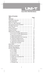
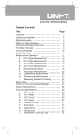
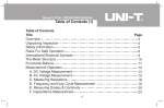
Model UT205A/206A: OPERATING MANUAL
Table of Contents
Title
Overview
Unpacking Inspection
Safety Information
Rules For Safe Operation
International Electrical Symbols
The Meter Structure
Functional Buttons
Display Symbols
Measurement Operation
A. AC Current Measurement
B. DC Voltage Measurement
C. AC Voltage Measurement
D. Measuring Resistance
E. Testing for Diodes and Continuity
F. Frequency and Duty Cycle (%) Measurement
(Duty Cycle: UT205A only)
G. Temperature Measurement (Model UT206A only)
1
Page
3
4
5
6
9
10
11
14
17
17
19
20
21
23
25
27
Model UT205A/206A: OPERATING MANUAL
Title
Operation of Hold Mode
The Use of Relative Value Mode(Model UT206A only)
The SELECT Button
Turning on the Display Backlight
Sleep Mode
General Specifications
Accuracy Specifications
A. AC Current
B. DC Voltage
C. AC Voltage
D. Resistance
E. Diode and Continuity Test
F. Frequency
G. Duty Cycle (Model UT205A only)
H. Temperature (Model UT206A only)
Maintenance
A. General Service
B. Replacing the Battery
2
Page
28
29
30
30
30
31
33
33
33
34
34
35
36
36
36
37
37
38
Model UT205A/206A: OPERATING MANUAL
Overview
This Operating Manual covers information on safety and cautions. Please read the
relevant information carefully and observe all the Warnings and Notes strictly.
Warning
To avoid electric shock or personal injury, read the “Safety Information” and
“Rules for Safety Operation” carefully before using the Meter.
The Model UT205A and UT206A (hereafter referred to as “the Meter”) are a low
consumption AC clamp meter with stabilize functions, safety operations, and reliable
performance.
In addition to the AC current feature, it can also measure AC/DC voltages, resistance,
diode, continuity, frequency and temperature.
Except where noted, the descriptions and instructions in this Operating Manual apply
to both the Model UT205A/UT206A.
3
Model UT205A/206A: OPERATING MANUAL
Unpacking Inspection
Open the package case and take out the Meter. Check the following items carefully
to see any missing or damaged part:
Item
1
2
3
4
5
Description
Operating Manual
Test Lead
Model UT206A: Point Contact Temperature Probe
9V Battery (NEDA 1604, 6F22 or 0006P) (installed inside the Meter)
Vinyl Bag
Qty
1 piece
1 pair
1 piece
1 piece
1 piece
In the event you find any missing or damage, please contact your dealer immediately.
4
Model UT205A/206A: OPERATING MANUAL
Safety Information
This Meter complies with the standards IEC61010: in pollution degree 2, overvoltage
category (CAT. II 600V / CAT III 300V) and double insulation.
CAT II: Local level, appliance, PORTABLE EQUIPMENT etc., with smaller transient
voltage overvoltages than CAT. III
CAT. III: Distribution level, fixed installation, with smaller transient overvoltages than
CAT. IV.
Under the influence of Radiated, Radio-Frequency Electromagnetic Field phenomenon,
the captioned model may malfunction and can self-recover after the test.
Use the Meter only as specified in this operating manual, otherwise the protection
provided by the Meter may be impaired.
In this manual, a Warning identifies conditions and actions that pose hazards to the
user, or may damage the Meter or the equipment under test.
A Note identifies the information that user should pay attention on.
International electrical symbols used on the Meter and in this Operating Manual are
explained on page 9.
5
Model UT205A/206A: OPERATING MANUAL
Rules For Safe Operation
Warning
To avoid possible electric shock or personal injury, and to avoid possible damage
to the Meter or to the equipment under test, adhere to the following rules:
Check for the lever is in good condition when measuring AC current.
Must center the wire (conductor) within the transformer jaw.
Before using the Meter inspect the case. Do not use the Meter if it is damaged
or the case (or part of the case) is removed. Look for cracks or missing plastic.
Pay attention to the insulation around the connectors.
Inspect the test leads for damaged insulation or exposed metal. Check the test
leads for continuity. Replace damaged test leads with identical model number
or electrical specifications before using the Meter.
Do not apply more than the rated voltage, as marked on the Meter, between the
terminals or between any terminal and grounding.
The rotary switch should be placed in the right position and no any changeover
of range shall be made during measurement is conducted to prevent damage
of the Meter.
When the Meter working at an effective voltage over 60V in DC or 42V rms in
AC, special care should be taken for there is danger of electric shock.
6
Model UT205A/206A: OPERATING MANUAL
Use the proper terminals, function, and range for your measurements.
When using the test leads, keep your fingers behind the finger guards.
Disconnect circuit power and discharge all high-voltage capacitors before testing
To avoid harms to you or damages to the Meter from electric shock, please do
not attempt to apply higher than 600V between the terminals and grounding.
Replace the battery as soon as the battery indicator
appears. With a low
battery, the Meter might produce false readings that can lead to electric shock
and personal injury.
When servicing the Meter, use only the same model number or identical electrical
specifications replacement parts.
The internal circuit of the Meter shall not be altered at will to avoid damage of
the Meter and any accident.
Soft cloth and mild detergent should be used to clean the surface of the Meter
when servicing. No abrasive and solvent should be used to prevent the surface
of the Meter from corrosion, damage and accident.
Turn the Meter off when it is not in use and take out the battery when not using
for a long time.
Constantly check the battery as it may leak when it has been using for some time,
replace the battery as soon as leaking appears. A leaking battery will damage
the Meter.
7
Model UT205A/206A: OPERATING MANUAL
Do not use or store the Meter in an environment of high temperature, humidity,
explosive, inflammable and strong magnetic field. The performance of the Meter
may deteriorate after dampened
8
Model UT205A/206A: OPERATING MANUAL
International Electrical Symbols
AC (Alternating Current)
DC (Direct Current)
AC or DC
Grounding
Double Insulated
Fuse
Deficiency of Built-In Battery
Continuity Test
Diode
Conforms to Standards of European Union
Warning. Refer to the Operating Manual
High Voltage Terminal
9
Model UT205A/206A: OPERATING MANUAL
The Meter Structure (see figure 1)
1. Transformer Jaws designed to pick up the AC current
flowing through the conductor.
2. Rotary Switch.
3. LCD Display.
4. Function Buttons
5. Input Terminals
6. Trigger. Press the lever to open the transformer
jaws. When the pressure on the lever is released,
the jaws will close.
1
2
3
6
4
5
(figure 1)
10
Model UT205A/206A: OPERATING MANUAL
Functional Buttons
Below table indicated for information about the functional button operations.
Button
Operation Performed
Turn the display backlight on and off.
In order to avoid the hazard arising from mistaken
readings in insufficient light or poor vision, please
use Display Backlight function.
Hz% (UT205A only)
1. At ACV or DCV range
Press the button to step through ACV or DCV,
frequency and duty cycle measurement.
The Meters enters the manual ranging
measurement mode after pressing the button
at the ACV or DCV measurement range. Turn
the rotary switch or switch off the Meter to
return to auto ranging measurement mode.
11
Model UT205A/206A: OPERATING MANUAL
Button
Hz% (UT205A only)
Operation Performed
The Meter is at the DCV – 400mV range or ACV
-4V range after returning from the Hz% cycle
measurement mode.
2. At Hz range
Press the button to step through frequency and
duty cycle measurement mode.
REL
(UT206A only)
SELECT
Press REL to enter and exit the REL mode in any
measuring mode except in frequency and duty cycle,
the Meter beeps.
UT206A: Switches between AC voltage and DC
Voltage measurement, and continuity and diode
measurement; the Meter beeps.
UT205A: Switches between continuity and diode
measurement; the Meter beeps.
12
Model UT205A/206A: OPERATING MANUAL
Button
SELECT
HOLD
Operation Performed
When it is under sleep mode, press to activate
the Meter at the effective measurement range,
e.g. continuity buzzer. Auto power off feature will
be disabled until switch off and turn on the Meter
again.
Press HOLD to enter and exit the Hold mode in any
mode, the Meter beeps.
13
Model UT205A/206A: OPERATING MANUAL
Display Symbols (see figure 2)
(figure 2)
14
Model UT205A/206A: OPERATING MANUAL
Number
1
2
3
Symbol
4
5
%
Percent: Used for duty cycle measurements.
A
Indicator for AC current
6
Hz, kHz, MHz
Hertz. The unit of frequency.
Kilohertz. 1x 10³ or 1000 hertz.
Megahertz. 1x10⁶ or 1,000,000 hertz.
7
,k ,M
Ohm. The unit of resistance.
kilohm. 1 x 10³ or 1000 ohms.
Megaohm. 1x10⁶ or 1,000,000 ohms.
AC
Meaning
Data hold is active.
Indicator for AC Voltage.
The battery is low.
Warning: To avoid false readings, which could lead to
possible electric shock or personal injury, replace the
battery as soon as the battery indicator appears.
15
Model UT205A/206A: OPERATING MANUAL
Number
8
Symbol
The continuity buzzer is on.
Test of diode
9
10
o
C
Centigrade. The unit of temperature.
The relative value mode is on to display the stored
value minus the present
11
12
Meaning
V, mV
Volts. The unit of voltage.
Millivolt. 1 x 10⁻³ or 0.001 volts.
16
Model UT205A/206A: OPERATING MANUAL
Measurement Operation
Make sure the Sleep Mode is not on if you found there
is no display on the LCD after turning on the Meter.
Make sure the Low Battery Display
is not on;
otherwise false readings may be provided.
Pay extra attention to the
symbol which is located
besides the input terminals of the Meter before carrying
out measeurement.
Make sure you are in the proper measurement range
before carrying out measurement.
A. AC Current Measurement (See figure 3)
(figure 3)
Warning
The measurement value obtained is wrong if testing two or more current
conductors at the same time.
17
Model UT205A/206A: OPERATING MANUAL
To measure current, do the following:
1. Set the rotary switch to the current measurement mode.
2. Check the lever is in good condition.
3. Press the lever to open the transformer jaws.
4. Center the conductor within the transformer jaw.
The measured value shows on the display, it is a effective value of sine wave
(mean value response).
Note
When current measurement has been completed, disconnect the connection
between the conductor under test and the jaw, and remove the conductor away
from the transformer jaw of the Meter.
18
Model UT205A/206A: OPERATING MANUAL
B. DC Voltage Measurement (See figure 4)
Warning
To avoid harms to you or damages to the Meter
from electric shock, please do not attempt to
measure voltages higher than 600V although
readings may be obtained.
To measure DC voltage, connect the Meter as follows:
1. Insert the red test lead into the V terminal and the
black test lead into the COM terminal.
2. Set the rotary switch to DC voltage measurement
mode.
3. Connect the test leads across with the object being
measured.
The measured value shows on the display.
19
Red
(figure 4)
Black
Model UT205A/206A: OPERATING MANUAL
Note
In each range, the Meter has an input impedance of 10M . This loading effect
can cause measurement errors in high impedance circuits. If the circuit impedance
is less than or equal to 10k , the error is negligible (0.1% or less).
When DC voltage measurement has been completed, disconnect the connection
between the testing leads and the circuit under test, and remove the testing leads
away from the input terminals of the Meter.
C. AC Voltage Measurement (See figure 4)
AC Voltage measurement is an auto ranging measurement mode.
Note:
Follow the same procedure as the DC Voltage Measurement mode. When you
using UT206A to carry out the measurement, use SELECT button to switch
between ACV and DCV.
20
Model UT205A/206A: OPERATING MANUAL
D. Measuring Resistance (see figure 5)
Warning
To avoid damages to the Meter or to the devices
under test, disconnect circuit power and discharge
all the high-voltage capacitors before measuring
resistance.
To measure resistance, connect the Meter as follows:
1. Insert the red test lead into the
terminal and
the black test lead into the COM terminal.
2. Set the rotary switch to .
3. Connect the test leads across with the object being
measured.
The measured value shows on the display.
Red
Black
(figure 5)
Note
The test leads can add 0.1
to 0.3
21
of error to resistance measurement.
Model UT205A/206A: OPERATING MANUAL
To obtain precision readings in low-resistance measurement, that is the range of
400.0 , short-circuit the input terminals beforehand, using the relative measurement
function button REL to automatically subtract the value measured when the
testing leads are short-circuited from the reading.
For high-resistance measurement (>1M ), it is normal to take several seconds
to obtain a stable reading.
When resistance measurement has been completed, disconnect the connection
between the testing leads and the circuit under test, and remove the testing leads
away from the input terminals of the Meter.
22
Model UT205A/206A: OPERATING MANUAL
E. Testing for Diodes and Continuity (See figure 6)
Warning
To avoid damages to the Meter or to the devices
under test, disconnect circuit power and discharge
all the high-voltage capacitors before testing for
continuity.
Red
Black
To test for diodes and continuity, connect the Meter as
below:
1. Insert the red test lead into the
terminal and the
(figure 6)
black test lead into the COM terminal.
2. For diode test
a. Set the rotary switch to
.
b. For forward voltage drop readings on any semiconductor component, place the
red test lead on the component’s anode and place the black test lead on the
component’s cathode.
The measured value shows on the display.
23
Model UT205A/206A: OPERATING MANUAL
3. For continuity test:
a. Press SELECT to switch between Diode and Continuity test.
b. Connect the test lead to the two end of the circuit under test.
c. The buzzer sounds if the resistance of a circuit under test is less than 100 .
Note
In a circuit, a good diode should still produce a forward voltage drop reading of
0.5V to 0.8V; however, the reverse-voltage drop reading can vary depending on
the resistance of other pathways between the probe tips.
Connect the test leads to the proper terminals as said above to avoid error display.
The LCD will display OL indicating diode being tested is open or polarity is reversed.
The unit of diode is Volt (V), displaying the forward voltage drop readings.
When diode and continuity testing has been completed, disconnect the connection
between the testing leads and the circuit under test, and remove the testing leads
away from the input terminals of the Meter.
24
Model UT205A/206A: OPERATING MANUAL
F. Frequency and Duty Cycle (%) Measurement (See figure 7)
UT205A has both frequency and duty cycle
measurement feature UT206A has only frequency
measurement feature
To measure frequency and duty cycle, connect the
Meter as follows:
Hz%
1. UT205A
a. Insert the red test lead into the Hz% terminal
a the black test lead into the COM terminal.
b. Set the rotary switch to Hz; press Hz% button
to switch between Hz and Duty cycle
(figure 7)
measurement mode.
c. Or set the rotary to ACV or DCV range, then
press Hz% button to switch between ACV or DCV, Hz and Duty cycle measurement
mode. But the accuracy will have a little difference based on the input frequency
and wave.
Red
25
Black
Model UT205A/206A: OPERATING MANUAL
d. Connect the test leads across with the object being measured.
The measured frequency value or duty cycle value shows on the display.
2. UT206A
a. Insert the red test lead into the Hz terminal and the black test lead into the
COM terminal.
b. Set the rotary switch to Hz.
c. Connect the test leads across with the object being measured.
The measured frequency value shows on the display.
Note
When frequency and duty cycle measurement has been completed, disconnect
the connection between the testing leads and the circuit under test, and remove
the testing leads away from the input terminals of the Meter.
26
Model UT205A/206A: OPERATING MANUAL
G. Model UT206A: Temperature Measurement (See figure 8)
To measure temperature, connect the Meter as follows:
o
1. Insert the red temperature probe into the C terminal
and the black temperature probe into the COM terminal.
o
2. Set the rotary switch to C.
3. Place the temperature probe to the object being
measured.
The measured value shows on the display.
Red
Black
Note
When there is no temperature probe inserted into the
terminals, the LCD displays OL.
(figure 8)
The included point contact temperature probe can only
o
be used up to 250 C. For any measurement higher than that, it is necessary to
use another type of temperature probe.
When temperature measurement has been completed, disconnect the connection
between the testing leads and the circuit under test, and remove the testing leads
away from the input terminals of the Meter.
27
Model UT205A/206A: OPERATING MANUAL
Operation of Hold Mode
Warning
To avoid possibility of electric shock, do not use Hold mode to determine if
circuits are without power. The Hold mode will not capture unstable or noisy
readings.
The Hold mode is applicable to all measurement functions.
Press HOLD to enter Hold mode; the Meter beeps.
Press HOLD again or turn the rotary switch to exit Hold mode; the Meter beeps.
In Hold mode, is displayed.
28
Model UT205A/206A: OPERATING MANUAL
The Use of Relative Value Mode (UT206A only)
The REL mode applies to all measurement functions except frequency and duty
cycle. It subtracts a stored value from the present measurement value and displays
the result.
For instance, if the stored value is 20.0V and the present measurement value is
22.0V, the reading would be 2.0V. If a new measurement value is equal to the stored
value then display 0.0V.
To enter or exit REL mode:
Use rotary switch to select the measurement function before selecting REL . If
measurement function changes manually after REL is selected, the Meter exits
the REL mode.
Press REL to enter REL mode, auto ranging turns off, and the present
measurement range is locked and stored as the stored value. All the measurements
done after will be automatically subtract this stored value.
Press REL again to exit REL mode and return to common measurement mode.
If you want to enter the auto ranging measurement mode or other ranges, please
turn the rotary switch or power off the Meter and start again.
29
Model UT205A/206A: OPERATING MANUAL
The SELECT Button
It uses for selecting the required measurement function when there is more than
one function at one position of the rotary switch.
Turning on the Display Backlight
Warning
In order to avoid the hazard arising from mistaken readings in insufficient
light or poor vision, please use Display Backlight function.
Press and hold button for over 2 seconds to turn the Display Backlight on.
Press
button again to turn the Display Backlight off, otherwise it will stay
on continuously.
Sleep Mode
To preserve battery life, the Meter automatically turns off if you do not turn the rotary
switch or press any button for around 15 minutes.
The Meter can be activated by turning the rotary switch or pressing the effective
button, it will return to working mode.
30
Model UT205A/206A: OPERATING MANUAL
General Specifications
Maximum Voltage between
any Terminals and Grounding:
Maximum Current Measurement:
of Transformer Jaw:
Maximum Jaw Size:
Maximum Display:
Overload Display:
Range:
Polarity Display:
Measurement Speed:
Temperature:
Relative Humidity:
Altitude:
600V rms or 600V DC.
1000A.
40mm.
Digital: 3999, 3 3/4 digits
OL
Auto
Negative display: “-“
Updates 3 times/second.
o
o
o
o
Operating: 0 C to +40 C (32 F to+104 F).
o
o
o
o
Storage: -10 C to +50 C (14 F to +122 F).
o
o
o
75% @ 0 C to 40 C; 70% @ -10 to 50 C.
Operating: 2000 m.
Storage: 10000 m.
31
Model UT205A/206A: OPERATING MANUAL
Battery Type:
Battery Deficiency:
Dimensions (HxWxL):
Weight:
Safety/Compliances:
One piece of 9V (NEDA1604 or 6F22 or 006P).
Display
236mm x 97mm x 40mm
Approximate 350g (battery included).
IEC61010 CAT. II 600V / CAT III 300V overvoltage
and double insulation standard.
Certifications:
Auto power off
Accuracy Specifications
Accuracy: (a% reading + b digits), guarantee for 1 year.
o
o
Operating temperature: 23 C 5 C.
Relative humidity: 75%.
32
Model UT205A/206A: OPERATING MANUAL
A. AC Current
Range
Resolution
400A
0.1A
1000A
1A
Accuracy
Remarks
(1.5%+5)
800A
>800A
Frequency response 50Hz~60Hz.
Display effective value of sine wave
(2%+5)
(mean value response).
(3%+5)
B. DC Voltage
Range
Resolution
400mV
100 V
4V
1mV
40V
10mV
400V
100mV
600V
1V
Accuracy Overload Protection
Remarks
(0.8%+3)
(0.8%+1)
600V DC
600V AC
(1%+3)
33
Input impedance:
around 10M .
Model UT205A/206A: OPERATING MANUAL
C. AC Voltage
Range Resolution Accuracy
40V
1mV
40V
10mV
400V
100mV
600V
1V
(1.2%+5)
Overload
Protection
600V DC
600V AC
(1.5%+5)
Remarks
Input impedance around 10M .
Displays effective value of sine
wave (mean value response).
Frequency response:
40Hz ~ 400Hz.
D. Resistance
Range
Resolution
Accuracy
400
0.1
(1.2%+2)
4k
1
(1%+2)
Overload Protection
500V DC or AC
34
Model UT205A/206A: OPERATING MANUAL
Range
Resolution
Accuracy
40k
10
400k
100
4M
1k
(1.2%+2)
40M
10k
(1.5%+2)
Overload Protection
(1%+2)
500V DC or AC
E. Diode and Continuity Test
Function
Diode
Range
Resolution
Overload
1mV
500V DC or AC
Continuity
Remarks
Displays the nearest value
of forward voltage drop
Buzzer beeps when
100
0.1
35
Model UT205A/206A: OPERATING MANUAL
F. Frequency (auto-ranging)
Range Resolution Accuracy Overload Protection
10Hz10MHz
Min
0.001Hz
(0.1%+3)
500V DC or VAC
Remarks
Input Voltage:
1MHz: 300mV rms a 30V rms;
1MHz: 600mV rms a 5V rms
G. Duty Cycle (Model UT205A only)
Range
Resolution
0.1%-99.9%
0.1%
Accuracy
For reference only
Overload Protection
500V DC or AC
H. Temperature (Model UT206A only)
Range
o
Resolution
Accuracy
o
(4%+4)
-40 C~0 C
o
o
1 C~400 C
o
Overload Protection
o
1C
(2%+8)
o
(3%+10)
401 C~1000 C
36
500V DC or AC
Model UT205A/206A: OPERATING MANUAL
Maintenance
This section provides basic maintenance information including battery replacement
instruction.
Warning
Do not attempt to repair or service your Meter unless you are qualified to do
so and have the relevant calibration, performance test, and service information.
To avoid electrical shock or damage to the Meter, do you get water inside the
case.
A. General Service
Periodically wipe the case with a damp cloth and mild detergent. Do not use
abrasives or solvents.
To clean the terminals with cotton bar with detergent, as dirt or moisture in the
terminals can affect readings.
Turn the Meter to OFF position when it is not in use.
Take out the battery when it is not using for a long time.
Do not use or store the Meter in a place of humidity, high temperature, explosive,
inflammable and strong magnetic field.
37
Model UT205A/206A: OPERATING MANUAL
B. Replacing the Battery (See figure 9)
Warning
To avoid false readings, which could lead to
possible electric shock or personal injury,
replace the battery as soon as the battery
indicator “ ” appears.
Make sure the transformer jaw and the test leads
are disconnected from the circuit being tested
before opening the case bottom.
Screw
(figure 9)
Make sure the test leads are removed from the input terminals.
38
Model UT205A/206A: OPERATING MANUAL
To replace the battery:
1. Turn the rotary switch of the Meter to OFF position and remove all the connections
from the terminals.
2. Remove the screw from the battery compartment, and separate the battery
compartment from the case bottom.
3. Remove the battery from the battery compartment.
4. Replace the battery with a new 9V battery (NEDA1604, 6F22 or 006P) and or a
1.5V battery (AAA).
5. Rejoin the case bottom and battery compartment, and reinstall the screw.
** END **
39
Model UT205A/206A: OPERATING MANUAL
Copyright 2006 Uni-Trend Group Limited.
All rights reserved.
Manufacturer:
Uni-Trend Technology (Dongguan) Limited
Dong Fang Da Dao
Bei Shan Dong Fang Industrial Development District
Hu Men Town, Dongguan City
Guang Dong Province
China
Postal Code: 523 925
Headquarters:
Uni-Trend Group Limited
Rm901, 9/F, Nanyang Plaza
57 Hung To Road
Kwun Tong
Kowloon, Hong Kong
Tel: (852) 2950 9168
Fax: (852) 2950 9303
Email: [email protected]
http://www.uni-trend.com
40