1
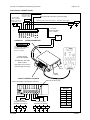
Carson Manufacturing Co., Inc.
5451 North Rural Street
Indianapolis, IN 46220
Phone: (888) 577-6877 Fax: (317) 254-2667
www.carsonsirens.com
SC-550-10
REMOTE
SIREN AMPLIFIER / LIGHT CONTROL
INSTALLATION AND OPERATING
INSTRUCTIONS
Sound Hazard - Sound level from siren speaker (>120dBA @ 10 feet) may cause hearing damage.
Do not operate siren without adequate hearing protection for you and anyone in immediate vicinity.
(Ref. OSHA 1910.95 for occupational noise exposure guidelines)
Page 2 of 12
SC-550-10 Installation and Operating Instructions
TABLE OF CONTENTS
GENERAL DESCRIPTION ....................................................................................3
SPECIFICATIONS .................................................................................................3
INSTALLATION .....................................................................................................4
SAFETY PRECAUTIONS ..................................................................................4
UNPACKING .....................................................................................................4
OPTION SWITCHES .........................................................................................4
ELECTRICAL CONNECTIONS .........................................................................5
MOUNTING .......................................................................................................7
RADIO VOLUME ADJUST ................................................................................7
OPERATION..........................................................................................................8
GENERAL..........................................................................................................8
SIREN CONTROLS ...........................................................................................8
Power Switch / PA Volume ...........................................................................8
Rotary Function Switch .................................................................................8
PA .................................................................................................................8
Siren Button and Auxiliary Siren Input ..........................................................8
Horn Ring Cycler 2 (HRC2) ..........................................................................8
Cutout ...........................................................................................................8
LIGHT CONTROLS ...........................................................................................9
Slide Switch ..................................................................................................9
Slide Switch Reverse ....................................................................................9
Automatic Siren ............................................................................................9
Auxiliary Output Switches .............................................................................9
Legends ........................................................................................................9
SERVICE .............................................................................................................10
PROBLEMS .........................................................................................................10
PARTS .................................................................................................................11
RETURN ..............................................................................................................11
LIMITED WARRANTY .........................................................................................11
INSTALLATION INFORMATION .........................................................................12
NOTICE
Due to continuous product improvements, we must reserve the right to change any specifications and information,
contained in this manual at any time without notice.
Carson Manufacturing Co., Inc. makes no warranty of any kind with regard to this manual, including, but not limited to, the implied warranties of merchantability and fitness for a particular purpose.
Carson Manufacturing Co., Inc. shall not be liable for errors contained herein or for incidental or consequential
damages in connection with the furnishing, performance, or use of this manual.
6/30/04
CP4818B
SC-550-10 Installation and Operating Instructions
Page 3 of 12
GENERAL DESCRIPTION
The SC-550 Remote Siren Amplifier with integrated Lighting Control is a premium unit designed
for single or dual 100W speaker use. A remote hand control is connected to the amplifier with a
thin cable. A 6-position rotary switch controls the primary operating modes of Phaser, Yelp, Wail,
Manual, Horn and Radio. A siren button and auxiliary siren input is provided for control of the
output tone, depending on the rotary switch setting. An integral microphone provides PA function.
The power switch is combined with the PA volume control. A hole is provided in the amplifier to
adjust Radio volume. A 4-position progressive slide switch controls primary lighting and may
automatically activate the siren. Non-progressive slide switch outputs provided for tailored lighting. Four auxiliary output pushbuttons provide for controlling additional lighting or other devices.
A latching siren cutout input is provided for connection to a door switch, etc. to disable the siren
when exiting the vehicle. An 8-position DIP switch on the amplifier allows selection of various
options: Two-Tone to replace Phaser, Phaser disable, Horn disable , short Manual, and Horn Ring
Cycler 2 (HRC2). Auxiliary siren and cutout input activation polarity along with disabling automatic
siren and slide switch reverse are additional options. The hand control is backlighted with LED's
for night visibility. The siren amplifier utilizes short circuit, high voltage, and reverse polarity protection systems for maximum service life over a wide temperature range. The slide switch and
auxiliary outputs are fused individually.
SPECIFICATIONS
Standby Current
Audio Frequency
Siren Amplifier
11 - 16 VDC (negative ground)
8 AMPS (@14 VDC - single 100W speaker)
16 AMPS (@14 VDC - dual 100W speakers)
Less than 200 ma
200Hz - 10 kHz + 3db
Audio Distortion
Audio Output
Audio Input
Less than 3% (@1 kHz - single 100W speaker)
40 watts (@14 VDC - single 100W speaker)
400 ohms + 10%
Output Power
105 WATTS RMS MAX. (15 VDC - single 100W speaker)
180 WATTS RMS MAX. (15 VDC - dual 100W speakers)
700Hz - 1500Hz (Two-Tone and Horn = 435 & 585Hz)
Input Voltage
Input Current
Siren Frequency
Tones / Cycle Rates
Cycle Rates
Horn
109 CPS
Wail
13 CPM
Yelp
190 CPM
Phaser
15 CPS
Two-Tone
60 CPM
High Voltage Prot.
Short Circuit Current
Operating Temp.
16 - 18 VDC will cause siren output to cease, resume at normal
50 AMPS (supply circuit must be capable of supplying this)
-15° F to +140°F
Controls
6-position rotary mode switch (Phaser, Yelp, Wail, Manual, Horn and Radio).
Momentary push-button Siren switch.
PA volume with Power switch on Hand Control, Radio volume on Amplifier.
Auxiliary input connection programmable for positive or negative activation.
Cutout input connection programmable for positive or negative latching cutout operation.
(2) Negative, (2) Speaker, (2) Radio, Cutout, Auxiliary Siren, (2) non-progressive slide
switch outputs (500mA Max. per output)
Note: positive siren connection is through high current input
Light Controls
11 - 16 VDC (negative ground)
Connections
(10-Pin Conn.)
Voltage
Controls
High Current Input
Slide Switch Outputs
4 Auxiliary Outputs
Size
Weight
CP4818B
4-position progressive slide switch with automatic siren activation
(4) auxiliary pushbuttons
(2) pressure terminals, 140 AMPS Max. not including siren input current
(3) pressure terminals, 20 AMPS Max. per terminal
(4) pressure terminals, 20 AMPS Max. per terminal
General
Hand Control: 2-3/4" Wide, 1" Deep, 6" High
Amplifier: 7-1/2" Wide, 6-3/4" Deep, 2-1/8" High
5-1/2 LBS.
6/30/04
Page 4 of 12
SC-550-10 Installation and Operating Instructions
INSTALLATION
Proper installation of the unit is essential for years of safe, reliable operation. Please read all
instruction before installing the unit. Failure to follow these instructions can cause serious damage to the unit or vehicle and may void warranties.
SAFETY PRECAUTIONS
For the safety of the installer, vehicle operator, passengers and the community please observe
the following safety precautions. Failure to follow all safety precautions and instructions may
result in property damage, injury or death.
Qualifications - The installer must have a firm knowledge of basic electricity, vehicle electrical
systems and emergency equipment.
Sound Hazard - Sound level from siren speaker (>120dBA @ 10 feet) may cause hearing damage.
Do not operate siren without adequate hearing protection for you and anyone in immediate vicinity.
(Ref. OSHA 1910.95 for occupational noise exposure guidelines)
Hand Control Location - Locate the hand control for easy access by the vehicle operator. DO
NOT locate in air bag deployment area.
Amplifier Mounting - DO NOT mount in air bag deployment area. Assure clearances before
drilling in vehicle.
Wiring - Use wiring capable of handling the current required. Make sure all connections are tight.
Route wiring to prevent wear, overheating and interference with air bag deployment. Install and
check all wiring before connection to vehicle battery.
Testing - Test all functions after installation to assure proper operation. Test vehicle operation to
assure no damage to vehicle.
Keep These Instructions - Keep these instructions in the vehicle or other safe place for future
reference. Advise the vehicle operator of the location.
UNPACKING
Inspect contents for shipping damage. If found alert carrier immediately. Contents should include hand control, amplifier, removable pressure connector, and these instructions. Contact
supplier immediately if any components are missing.
OPTION SWITCHES
Various options can be controlled by turning on or off any of 8 DIP switches on the amplifier.
Switch 1 On:
Positive Cutout Input Polarity - Cutout is normally activated with negative input. This switch changes to positive activation.
Switch 2 On:
Positive Auxiliary Siren Input Polarity - Auxiliary siren is normally activated with negative input. This switch changes to positive activation.
Switch 3 On:
Two-Tone - Two-Tone replaces Phaser function.
Switch 4 On:
Phaser Disable - The Phaser and Two-Tone function are disabled.
Switches 3 & 4 On:
Horn Ring Cycler 2 option (HRC2) - This option allows selection of Wail,
Yelp, and Phaser by repeatedly tapping the Siren button, horn ring or other
switch connected to the auxiliary siren input. Tapping the horn ring twice
quickly will stop siren tones. Holding the horn ring produces Horn.
NOTE: Earlier units with S/N lower than 04190000 have a different version of HRC. In this case the siren tones cycle through Standby, Wail,
Yelp, and Phaser. The tone is stopped by cycling to Standby.
Switch 5 On:
Horn Disable - The Horn function is disabled.
Switch 6 On:
Short Manual - The Manual function can be set to immediately cut off
when the Siren button is released.
Switch 7 On:
Automatic Siren Disable - The Automatic Siren feature associated with
the slide switch may be disabled.
Switch 8 On:
Slide Switch Reverse - The progressive slide switch normally activates
L1 output in position 1 and L1, L2, L3 outputs in position 3. Setting this
option on activates L1, L2, L3 outputs in position 1 and L1 output in position 3.
6/30/04
CP4818B
SC-550-10 Installation and Operating Instructions
Page 5 of 12
ELECTRICAL CONNECTIONS
(2) #18 AWG
(#16 - 2 SPKR)
2-SPKR - Connect for
same phase (+ to +)
(2) #22 AWG
Connect to output
jack, terminals or
speaker of radio
RADIO
Auxiliary Siren Input #22 AWG (See next page)
Cutout Input #22 AWG (See next page)
Slide Switch Non-Progressive Output 2 #22 AWG (500mA Max.)
RELAY
Slide Switch Non-Progressive Output 1 #22 AWG (500mA Max.)
••••••••••
→
→
→
→
→
→
→
→
→
→
#14 AWG
Use second lead
for 2 - SPKR
SPKR
SPKR
OUT2
OUT1
RAD
RAD
AUX
CUT
NEG
NEG
CP4833-10
RELAY
BAT
+
10-PIN CONNECTOR
Screw terminals face down.
Locking screws on side hold
connector to amp box.
Wiring not supplied.
Positive Supply
Use both terminals
#6 AWG Max. Wire Size
Each Terminal
(140A Max. Input Current)
(Not including siren amp)
DIP
Switch
Radio
Volume
LIGHT CONTROL OUTPUTS
Each Light Output Protected with 25A Fuse
20A Fuse for Siren Amp
Recommended
Wire Size
Amps
Size
5 - 10
#16
Slide Switch
Progressive Outputs
(20A Max. per Output)
LOAD LOAD LOAD
CP4818B
Auxiliary Outputs
(20A Max. per Output)
LOAD LOAD LOAD LOAD
10 - 15
#14
15 - 25
#12
25 - 40
#10
40 - 60
#8
60 - 80
#6
Use next larger size
if longer than 10 ft.
6/30/04
Page 6 of 12
SC-550-10 Installation and Operating Instructions
ELECTRICAL CONNECTIONS
Connections are made using pressure terminal connectors. Legends on the unit identify each
terminal function. Attach leads by stripping 3/8", inserting into connector and clamp by tightening
screw. Make sure the screw is tight and the wire can't be pulled out. Failure to adequately
tighten the screw can result in improper operation or burning the connector and wire.
Positive Supply:
Due to the high current nature of this unit, an appropriate supply line is
required. In addition to the high current delivered to devices on the outputs, the siren amplifier will require peak currents up to 50 amps for adequate short circuit protection and reliable operation. The preferred source
is directly at the vehicle battery.
Negative Supply:
The negative supply line is for the siren amplifier. The siren amplifier will
require peak currents up to 50 amps for adequate short circuit protection
and reliable operation. The preferred source is directly at the vehicle battery.
Speaker:
Both connections must be used. Two speakers may be connected in parallel. Observe polarity (phasing) for maximum sound output.
Radio (Optional):
Both connections must be used. The input is isolated and polarity is not
important. May need to adjust RADIO VOLUME on side of amplifier.
Auxiliary Siren
(Optional):
The auxiliary siren input allows activation of the Siren button with an external source. The OPTION SWITCH determines polarity of activation.
+VDC
HORN
RING
SWITCH
+VDC
Added
SPDT
Switch
HORN
RING
SWITCH
SPLICE
HORN
MOMENTARY
FOOT
SWITCH
AUX
HORN
AUX
+VDC Switching examples
Cutout (Optional):
-VDC
switching
example
The cutout input turns off any siren tone when activated, and remains off
until a siren control is changed. The OPTION SWITCH determines polarity
of activation.
+VDC
DOOR
SWITCH
SPLICE
DOME
LIGHT
ADDED
DOOR
SWITCH
CUT
CUT
+VDC Switching
Example
6/30/04
-VDC
switching
example
CP4818B
SC-550-10 Installation and Operating Instructions
Page 7 of 12
L1, L2, L3 Outputs:
These outputs are controlled by the slide switch in a progressive fashion.
Outputs are fused.
S1 to S4 Outputs:
These outputs are controlled individually by pushbutton switch 1 to 4.
Outputs are fused.
OUT1,2 Outputs
(Optional):
Controlled by the slide switch in a non-progressive fashion.
See Slide Switch under Light Controls.
These outputs are not fused and are intended to control external relays.
When turned on the output supplies +VDC @ 500mA max.
When turned off the output is open (high impedance).
MOUNTING - Hand Control
Choose a mounting location convenient to the operator and away from any air bag deployment
areas. Consider cable routing to amplifier as well as PA use. Mount the hand control with supplied Hook and Loop tape (VELCRO). If the tape method is not preferred, the hand control may
be mounted several ways including a cell phone holder. Plug cable into amplifier, no other electrical connections are necessary.
MOUNTING - Amplifier
Select a location for the amplifier in an area such as the driver compartment firewall, under a seat,
etc. Mounting the amplifier in the engine compartment or in an area directly exposed to weather
is not recommended. Assure adequate ventilation to prevent overheating. Allow clearance for
wiring and radio adjustment. Inspect behind mounting area for clearance. Mark the location of
the mounting holes to be drilled.
Drill 4 holes (up to 1/4" diameter) to mount the amplifier to the vehicle. Install the removable pressure connector and make all electrical connections before final mounting (See ELECTRICAL
CONNECTIONS). The connector may be secured with the two locking screws. Then mount the
amplifier to the vehicle using appropriate hardware (not supplied).
RADIO VOLUME ADJUST
If the Radio repeat mode of the siren is going to be used then the RADIO VOLUME control may
need to be adjusted. This is a one time setting which depends on the radio connected and its
normal volume. On the hand control, set the slide switch to OFF, set the rotary switch to RADio,
and power switch to ON. With the volume on the radio itself set to normal level, set the RADIO
VOLUME control to the desired output level.
CP4818B
6/30/04
Page 8 of 12
SC-550-10 Installation and Operating Instructions
OPERATION
Sound Hazard - Sound level from siren speaker (>120dBA @ 10 feet) may cause hearing damage.
Do not operate siren without adequate hearing protection for you and anyone in immediate vicinity.
(Ref. OSHA 1910.95 for occupational noise exposure guidelines)
GENERAL
This unit is designed for easy operation under the stress associated with high-speed pursuit.
Most functions are accessible with one simple motion without repetitive activation of switches or
automatic timed switching that can interfere with desired operation.
Power Switch/PA Volume
SIREN CONTROLS
The combined power switch and volume control give power to the
hand control and adjust the PA volume. Power is turned OFF by
rotating the control counterclockwise until it “clicks”. Power is turned
ON and increased PA volume by rotating clockwise. The power
switch should be turned off when vehicle is not being used to conserve battery power.
The Rotary Function Switch selects various siren operating modes.
These modes are as follows:
Function Switch
PHaSeR: The siren produces a very fast warble tone. This mode
may be used at intersections or in highly congested areas. Horn and PA override available in this mode.
YELP:
The siren produces a moderate warble tone. This mode
may be used in lightly congested areas. Horn and PA
override available in this mode.
WAIL:
The siren produces a normal rise-fall tone pattern. This mode may be used on highways or areas with constant traffic flow. Yelp and PA override available in this mode.
MANual:
The siren rise-fall tone is controlled manually with the Siren button. PA override available in this mode.
HORN:
Also considered a standby mode. Horn and PA override available in this mode.
RADio:
This mode reproduces, or repeats, the output of a radio. The radio must be connected
and the RADIO VOLUME adjusted. PA override available in this mode.
The following OVERRIDE FUNCTIONS are for certain modes.
PA and Siren Button
PTT
PA:
By pressing the microphone PTT (Push to Talk) switch
on the side of the hand control, the siren will change to a
PA (Public Address) amplifier. The siren mode resumes
when the PTT is released. Adjust the PA Volume and
hold the MIC close to your lips for proper operation. PA
override is available in all modes.
HORN:
By momentarily pressing the Siren button or activating the auxiliary siren input, the
HORN tone is produced. The siren mode resumes when released. Horn override is
available in all modes except Radio and Wail.
YELP:
Only available in Wail mode. By momentarily pressing the Siren button or activating
the auxiliary siren input, the siren output is toggled between Wail and Yelp tone.
HRC2:
Horn Ring Cycler 2 is only available in Horn (Standby) mode and must be enabled
with the option switches. Tap the horn ring to bring the unit out of standby into Wail
tone. Repeatedly tapping the horn ring will cycle through Wail, Yelp, and Phaser
tones. Tapping the horn ring twice quickly will stop the siren tones and return the unit
to standby. Pressing and holding the horn ring will produce Horn tone until released.
Then the siren returns to its previous siren tone or standby.. If automatic siren is active, then tones are not stopped. See OPTION SWITCHES section for further details.
CUTOUT: The cutout input turns off any siren tone when activated, and remains off until a siren
control is changed.
6/30/04
CP4818B
SC-550-10 Installation and Operating Instructions
Page 9 of 12
LIGHT CONTROLS
A 4-position slide switch provides control of primary lighting functions. It also provides automatic
activation of the siren. Four pushbuttons for additional lighting or controlling other devices. The
power switch on the hand control must be ON for light controls to function.
Slide Switch
The slide switch provides progressive (additive) control of lighting
functions. Position 1 turns on L1 output. Position 2 turns on L1 and
L2 outputs. Position 3 turns on L1, L2, and L3 outputs. Position 3
also turns on the siren (Automatic Siren).
Slide Switch
The slide switch position outputs OUT1 and OUT2 are for setups
that require a non-progressive slide switch. Only Position 1 will turn
on OUT1. Only Position 2 will turn on OUT2. In Position 3 the L3
output can be used since only Position 3 will turn this on.
Note that OUT1 and OUT2 are not fused and intended to drive external relays. These outputs
can only drive loads up to 500mA each.
Slide Switch Reverse
The Option Switch can be set to reverse the slide switch positions. Position 1 and Position 3
operations are reversed or swapped.
Slide Switch Position
OFF
1
Slide Switch Reverse OFF
L1, L2, L3, OUT1, OUT2 ALL OFF
L1, OUT1 ON
Slide Switch Reverse ON
L1, L2, L3, OUT1, OUT2 ALL OFF
L1, L2, L3 ON
(Auto Siren)
2
L1, L2, OUT2 ON
L1, L2, OUT2 ON
3
L1, L2, L3 ON
(Auto Siren)
L1, OUT1 ON
Automatic Siren
Position 3 of the Slide Switch (or 1 with Slide Switch Reversed) provides Automatic Siren. If the
siren controls are set where there is no siren tone output, the Automatic Siren will override with
Wail. The only exception is PA Override or Cutout activation.
Automatic Siren may be disabled with the Option Switch.
Auxiliary Output Switches
Auxiliary Output Switches
Four pushbutton switches are provided for various other lighting
functions or device control. Legends above the switch light up
when the switch is on.
Legends
Different legends may be selected to match the device controlled
by aux output switch. A sheet of stick-on legends is supplied.
Select the legend and place centered over the legend area. Press down on the legend to stick
over clear window and tuck under rubber framing. Gently lift up on the sides of rubber framing to
help cover the edges of the legend.
To remove a legend, use a thin edge to gently push rubber frame aside and pry between legend
and clear window. Try not to puncture clear window. The stick-on adhesive is strong.
Blank (black) legends are provided for aux output switches with no function. The white background legends may be written on with permanent marker to create custom legends.
Legend
Area
Legend Label
Rubber Frame
1
CP4818B
Clear Window
6/30/04
Page 10 of 12
SC-550-10 Installation and Operating Instructions
SERVICE
This unit is designed to provide years of reliable service under even the worst conditions. Many
times there may appear to be a problem with the unit when the true problem is in the speaker(s),
controlled devices, or improper installation. The following chart shows typical symptoms and
possible causes.
A blown siren fuse doesn't necessarily mean that the unit is bad. If a speaker or speaker lead is
shorted the fuse will blow before the unit is damaged. Disconnect the SPKR leads and replace
the fuse. If the unit itself emits a low level sound when in the Yelp position it is OK. Check the
speaker(s) or leads for possible shorting.
25A Fuses are required for each light control output. Adequate fuse rating is required to prevent
overheating of the output connection block.
PROBLEMS
Symptom
Possible Cause
Check
No power or siren Power switch not turned on
output
Bad Speaker
Connector or connections loose
Siren fuse blown
Loose connection at power source
No siren tone High Voltage Protection
PA works
PA PTT button stuck
Cutout activated
Cutout Polarity Option set wrong
Does backlighting come on?
Do you hear a "pop" when turned on?
With siren on, yelp selected, listen for tone in amplifier.
Is an external fuse or circuit breaker used?
Are the power leads connected to a good buss?
The input voltage must be less than highest rating.
Does PTT button release properly?
Does the siren work when Cutout input is disconnected?
Is the Cutout Input Polarity option properly configured?
No PA
PA volume not set properly
Have you tried turning the PA volume control?
Distorted siren
sound
Intermittent siren
tone
Speaker assembly loose
Intermittent Aux Input connection
Low vehicle voltage
High Voltage Protection
Connector or connections loose
Loose connection at power source
PA PTT button activation
Circuit breaker in supply connection
Is the speaker bell or tip loose?
Is the Aux Siren Input used and wired properly?
The input voltage must be greater than lowest rating.
Is the vehicle voltage regulator working properly?
Is the connector tight on the back of the unit?
Check for loose leads back to power source.
Is something lying on the PTT button?
Is a circuit breaker used with at least a 50A rating?
Horn function
stuck on or
Manual or Phaser
stuck on
Siren button switch stuck
Aux Siren switch stuck
Aux Input improperly connected
Aux Input Polarity Option set wrong
Does the Siren button switch return fully when released?
Does the Aux Siren switch return fully when released?
Is the Aux Siren Input used and wired properly?
Is the AUX Siren Polarity option properly configured?
No Radio
Unit not connected to radio
Radio volume too low
Is the radio connected properly to the unit?
Can you here the radio in the vehicle?
Have you tried setting the Radio Volume Adjust?
Is the Two-Tone option set?
Wrong siren tone Two-Tone option selected
Phaser not work- Phaser disabled
ing
Horn not working Horn disabled
Is the Phaser Disable option set?
Manual stops
immediately
Automatic Siren
not working
Short Manual enabled
Is the Short Manual option set?
Automatic Siren disabled
Is the Automatic Siren Disable option set?
Light Output not
working
Light Output stays
on
Non-progressive
output not working
Slide switch
outputs turn on in
wrong order
Light Control Output fuse blown
Internal relay contacts bad
Internal relay contacts fused from
overheating
Internal switching transistor bad
Is the light or device shorting?
Is the output current limited to 20A?
Is the output current limited to 20A?
Slide Switch is reversed
Is the Slide Switch Reverse option set?
6/30/04
Is the Horn Disable option set?
Is the external relay coil shorting?
Is the output current limited to 500mA?
CP4818B
SC-550-10 Installation and Operating Instructions
Page 11 of 12
PARTS
Part
CP4177
CP4732
F-16SP/12276
CP4833-10
ATO/ATC 20A
ATO/ATC 25A
1555 KNOB
CP4895
CP4701
CP3902
CP4119
CP4818
Description
Cable, Coil Cord W/Modular Connector (Hand Control)
Control, 1K Vertical Trimmer (Amplifier)
Control, 1K PA Volume w/Power Switch (Hand Control)
Connector, 10-pin Siren w/Locking Screws (Wiring not included)
Fuse, 20 Amp Automotive (Siren)
Fuse, 25 Amp Automotive (Light Output)
Knob, Black Selector Switch
Label, Aux Output Legends
Relay, 40A Light Control Output
Switch, Rotary 6-Position Selector
Transistor, output (2 required) (Industry standard TIP36C, Not Texas Instruments)
Manual, SC-550-10 14 Instruction
Accessories
ED1753
Cable, kit, hand control extension 15FT (includes CP4652 shielded cable and CP4141 modular coupler)
RETURN
If you have any questions concerning this or any other Carson product, please contact our Technical Service Department at (888) 577-6877. Many issues can be handled over the phone. We
can also be reached via e-mail at [email protected]
If a product must be returned for any reason, please contact our Technical Service Department to
obtain a Returned Merchandise Authorization number (RMA#) before you ship the product to
Carson. Please write the RMA# clearly on the package near the mailing label. Be sure to provide
a return address, contact and phone number, along with a brief description of the problem.
LIMITED WARRANTY
Carson Manufacturing Company, Inc. warrants this new product to be free from defects
in material and workmanship, under normal use and service, for a period of five (5)
years from the date of delivery to the first user-purchaser.
During this warranty period the obligation of Carson Manufacturing is limited to repairing
or replacing, as Carson Manufacturing may elect, any part or parts of such product
which after examination by Carson Manufacturing is determined to be defective in material and/or workmanship.
This warranty does not cover labor charges for removal or re-installation of the product.
Fuses and lamps are not covered under this warranty.
This warranty does not extend to any unit that has been subjected to abuse, misuse,
improper installation or which has not been adequately maintained, nor to units which
have problems related to service or modification at any facility other than Carson Mfg.
THERE ARE NO OTHER WARRANTIES, EXPRESSED OR IMPLIED, INCLUDING
BUT NOT LIMITED TO, ANY IMPLIED WARRANTIES OF MERCHANTABILITY OR
FITNESS FOR A PARTICULAR PURPOSE. IN NO EVENT SHALL CARSON MANUFACTURING COMPANY, INC. BE LIABLE FOR ANY LOSS OF PROFITS OR ANY
INDIRECT OR CONSEQUENTIAL DAMAGES ARISING OUT OF ANY SUCH DEFECT
IN MATERIALS OR WORKMANSHIP.
CP4818B
6/30/04
Page 12 of 12
SC-550-10 Installation and Operating Instructions
INSTALLATION INFORMATION
MODEL: SC-550 _______________________
OPTIONS
SERIAL NO: __________________________
______ Two-Tone instead of Phaser
PURCHASE DATE: _____________________
______ Phaser and Two-Tone Disable
DEALER: _____________________________
______ HRC2 enabled
_____________________________________
______ Horn disabled
INSTALLER: __________________________
______ Short Manual
_____________________________________
______ Automatic Siren disabled
INSTALL DATE: ________________________
______ Slide Switch Reversed
Auxiliary Siren Connection ________________
______ Auxiliary Siren Input Polarity
Cutout Connection ______________________
______ Cutout Input Polarity
SLIDE SWITCH
L1: _______________________________
OUT1: _______________________________
L2: _______________________________
OUT2: _______________________________
L3: _______________________________________________________________________
AUXILIARY OUTPUTS
S1: _______________________________
S3: _______________________________
S2: _______________________________
S4: _______________________________
6/30/04
CP4818B