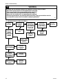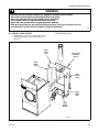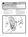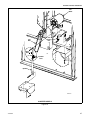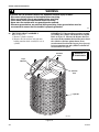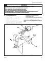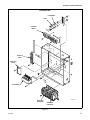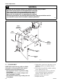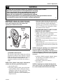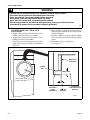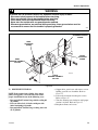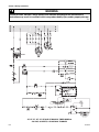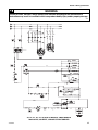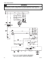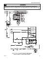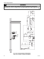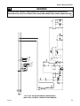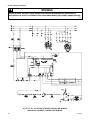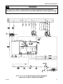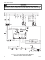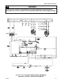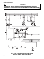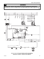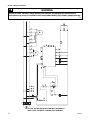
1
D55
SERVICE MANUAL
PUBLICATION DATE: 10/03
70276001
INDUSTRIAL DRYERS
Table of Contents
Section 1 – Safety Information
Locating An Authorized Service Person .................4
Section 2 – Introduction
Model Identification ................................................5
Customer Service ....................................................6
Serial Plate Location ...............................................6
Safety Warnings and Decals ...................................7
Safety Precautions for Servicing Tumblers ............7
Section 3 – Troubleshooting
1. Motor Does Not Start .......................................9
2. Motor Overload Protector Cycles
Repeatedly ......................................................10
3. Motor Runs But Cylinder Does Not Turn. .....10
4. Motor Does Not Stop .....................................10
5. Gas Burner Does Not Ignite ...........................11
6. Burner Ignites And Goes Out Repeatedly .....12
7. Burner Shuts off Prematurely ........................12
8. Burner Repeatedly Cycles Off On High Limit
Thermostat .....................................................13
9. Steam Valve or Burner Does Not Shut-off ...13
10. Clothes Do Not Dry .......................................14
11. Tumbler Overheating .....................................14
12. Burners Not Burning Properly - Gas Models 15
13. Loading Door Opens During Operation ........15
14. Tumbler Runs But No Steam To Coils - Steam
Models ............................................................15
15. Water In Steam Line - Steam Models ............16
16. Tumbler Will Not Start, Time On Drying Timer,
Door Closed ...................................................17
17. Motor Runs But Will Not Heat ......................18
18. Cylinder Turns, But Will Not Heat ................19
Section 4 – Grounding
19. Grounding Instructions ..................................21
Section 5 – Service Procedures
20.
21.
22.
23.
24.
25.
26.
Access Panel/Interior Control Box ................23
Control Fuse Holder .......................................23
Control Fuse ...................................................24
Signal Buzzer .................................................24
Load Ready Light ..........................................25
Ignition Reset Switch .....................................25
Emergency Stop Switch .................................25
27.
28.
29.
30.
31.
32.
33.
34.
35.
36.
37.
38.
39.
40.
41.
42.
43.
44.
45.
46.
47.
Push-To-Start Switch .....................................25
Cool Down and Heat Lights ..........................25
Cool Down and Heat Timers .........................27
Relay ..............................................................27
Reversing/Nonreversing Switch ....................27
Temperature Switch .......................................27
Temperature Control Board ...........................28
Electronic Control ..........................................28
Loading Door Assembly ................................30
Loading Door Handle ....................................30
Loading Door Switch .....................................30
Front Panel .....................................................31
Loading Door Hinge Lug ...............................33
Thermistor ......................................................33
Lint Panel Switch ...........................................34
Gas Valve .......................................................35
Igniter .............................................................35
Ignition Control ..............................................35
Burner Tube ...................................................35
Stove High Limit Thermostat ........................36
Cabinet High Limit Thermostat/ Load Ready
Thermostat .....................................................36
48. Steam Coils ....................................................37
49. Drive Guard Cover .........................................39
50. Airflow Switch ...............................................40
51. Cylinder Belt ..................................................40
52. Drive Belt .......................................................41
53. Step Pulley Assembly ....................................41
Critical Torques ....................................................42
54. Cylinder Sheave .............................................43
55. Motor Pulley ..................................................44
56. Jackshaft Assembly ........................................44
57. Cylinder Assembly ........................................44
58. Trunnion Bearings .........................................45
59. Fan Motor Drive And Fan Assembly ............46
60. Fan (60 Hertz Models) ...................................46
61. Fan (50 Hertz Models) ...................................46
62. Trunnion Shaft Assembly ..............................48
63. Cylinder Drive Motor ....................................49
64. Reversing Timer ............................................50
65. Reversing Contactor ......................................50
66. Fan Motor Contactor ......................................50
67. Transformer ...................................................50
(continued)
70276001
1
Section 6 – Adjustments
68.
69.
70.
71.
72.
73.
74.
Leveling .........................................................53
Main Gas Burner Air Inlet Shutters ...............54
Airflow Switch ...............................................55
Loading Door Strike ......................................55
Cylinder Belt ..................................................56
Drive Belt Tension .........................................59
Fan Belt Tension ............................................60
Section 7 – Wiring Schematics .........................61
AT, HT, PT, ST, UT, WT and XT Manual Timer
Models
208-230 VAC, 60 Hertz, 3 Phase Gas ..............62
380-415 VAC, 50 Hertz, 3 Phase Gas ..............63
460 VAC, 60 Hertz, 3 Phase Gas .....................64
208-230 VAC, 60 Hertz, 3 Phase Steam .........65
380-415 VAC, 50 Hertz, 3 Phase Steam .........66
460 VAC, 60 Hertz, 3 Phase Steam .................67
HU, PU, SU, UU and XU Manual Timer Models
380-415 VAC, 50 Hertz, 3 Phase Gas .............68
380-415 VAC, 50 Hertz, 3 Phase Steam .........69
AT, HT, PT, ST, UT, WT and XT Micro Control RM
Models
208-230 VAC, 60 Hertz, 3 Phase Gas .............70
380-415 VAC, 50 Hertz, 3 Phase Gas .............71
460-480 VAC, 60 Hertz, 3 Phase Gas .............72
208-230 VAC, 60 Hertz, 3 Phase Steam .........73
380-415 VAC, 50 Hertz, 3 Phase Steam .........74
460-480 VAC, 60 Hertz, 3 Phase Steam .........75
HU, PU, SU, UU and XU Micro Control RM Models
380-415 VAC, 50 Hertz, 3 Phase Gas .............76
380-415 VAC, 50 Hertz, 3 Phase Steam .........77
2
70276001
Section 1
Safety Information
Throughout this manual and on machine decals, you
will find precautionary statements (“CAUTION”,
“WARNING”, and “DANGER”) followed by specific
instructions. These precautions are intended for the
personal safety of the operator, user, servicer, and those
maintaining the machine.
DANGER
DANGER indicates the presence of a
hazard that will cause severe personal
injury, death, or substantial property
damage if the danger is ignored.
WARNING
WARNING indicates the presence of a
hazard that can cause severe personal
injury, death, or substantial property
damage if the warning is ignored.
In the interest of safety, some general precautions
relating to the operation of this machine follow.
WARNING
• Failure to install, maintain and/or operate
this product according to the
manufacturer’s instructions may result in
conditions which can produce serious
injury, death and/or property damage.
• Do not repair or replace any part of the
product or attempt any servicing unless
specifically recommended or published in
this Service Manual and unless you
understand and have the skills to carry
out the servicing.
• Whenever ground wires are removed
during servicing, these ground wires
must be reconnected to ensure that the
product is properly grounded and to
reduce the risk of fire, electric shock,
serious injury or death.
W006R2
CAUTION
CAUTION indicates the presence of a
hazard that will or can cause minor
personal injury or property damage if the
caution is ignored.
Additional precautionary statements (“IMPORTANT”
and “NOTE”) are followed by specific instructions.
IMPORTANT: The word “IMPORTANT” is used
to inform the reader of specific procedures where
minor machine damage will occur if the procedure
is not followed.
NOTE: The word “NOTE” is used to communicate
installation, operation, maintenance or servicing
information that is important but not hazard
related.
70276001
3
Section 1 Safety Information
IMPORTANT INFORMATION: During the
lifetime of a tumbler, it may require service. The
information contained in this manual was written
and is intended for use by qualified service
technicians who are familiar with the safety
procedures required in the repair of a tumbler, and
who are equipped with the proper tools and testing
equipment.
NOTE: The WARNING and IMPORTANT
instructions appearing in this manual are not meant
to cover all possible conditions and situations that
may occur. It must be understood that common
sense, caution and carefulness are factors which
CANNOT be built into this tumbler. These factors
MUST BE supplied by the person(s) installing,
maintaining or operating the tumbler.
Always contact your dealer, distributor, service agent
or the manufacturer on any problems or conditions you
do not understand.
WARNING
To reduce the risk of electric shock, fire,
explosion, serious injury or death:
• Disconnect electric power to the tumbler
before servicing.
• Never start the tumbler with any guards/
panels removed.
• Whenever ground wires are removed
during servicing, these ground wires
must be reconnected to ensure that the
tumbler is properly grounded.
W240
WARNING
Locating An Authorized Service
Person
Alliance Laundry Systems is not responsible for
personal injury or property damage resulting from
improper service. Review all service information
before beginning repairs.
Warranty service must be performed by an
authorized technician, using authorized factory
parts. If service is required after the warranty
expires, Alliance Laundry Systems also
recommends contacting an authorized technician
and using authorized factory parts.
Repairs that are made to your products by
unqualified persons can result in hazards
due to improper assembly or adjustments
subjecting you or the inexperienced person
making such repairs to the risk of serious
injury, electrical shock or death.
W007
CAUTION
If you or an unqualified person perform
service on your product, you must assume
the responsibility for any personal injury or
property damage which may result. The
manufacturer will not be responsible for
any injury or property damage arising from
improper service and/or service
procedures.
W008
4
70276001
Section 2
Introduction
Model Identification
Information in this manual is applicable to these models:
Gas
AT120L
AT120N
HA120L
HA120N
HT120L
HT120N
HU120L
HU120N
PA120L
PA120N
PT120L
PT120N
PU120L
PU120N
SA120L
Steam
SA120N
ST120L
ST120N
SU120L
SU120N
UA120L
UA120N
UT120L
UT120N
UU120L
UU120N
WT120L
WT120N
XT120L
XT120N
XU120N
AT120S
HT120S
HU120S
PT120S
PU120S
ST120S
ST120T
SU120S
UT120S
UU120S
WT120S
XT120S
XU120S
Includes models with the following control suffixes (7th and 8th characters):
RM – reversing OPL micro
RT – reversing manual timer
70276001
5
Section 2 Introduction
Customer Service
If literature or replacement parts are required, contact
the source from whom the machine was purchased or
contact Alliance Laundry Systems at (920) 748-3950
for the name and address of the nearest authorized
parts distributor.
For technical assistance, call (920) 748-3121.
Serial Plate Location
When calling or writing about your product, be sure to
mention model and serial numbers. Model and serial
numbers are located on serial plate as shown.
Serial
Plate
Junction Box
Cover
TMB1764S
6
70276001
Section 2 Introduction
Safety Warnings and Decals
SAFETY WARNINGS and decals have been provided
in key locations to remind you of important precautions
for the safe operation and maintenance of your tumbler.
Please take the time to review these warnings before
proceeding with service work.
All decals have been designed and applied to withstand
washing and cleaning. Decals should be checked
periodically to be sure they have not been damaged,
removed, or painted. Refer to the Parts Manual for
ordering replacement decals.
Safety Precautions for Servicing Tumblers
• Disconnect electrical service.
• Shut off supply gas valve before servicing gas
components.
• Access panel MUST be reinstalled after
inspection or servicing of tumbler is completed.
• Use a non-corrosive leak detecting compound to
check all pipe connections for gas leaks. DO NOT
USE AN OPEN FLAME TO CHECK FOR GAS
LEAKS!
• Belt guard MUST be reinstalled after inspection
or servicing of tumbler is completed.
• Contactor box cover MUST be reinstalled after
inspection or servicing of electric and/or reversing
tumbler is completed.
• Loading door switch MUST be operational before
putting tumbler into service.
• Junction box cover MUST be reinstalled after
inspection or servicing of tumbler is completed.
70276001
7
Section 2 Introduction
Notes
8
70276001
Section 3
Troubleshooting
WARNING
To reduce the risk of electric shock, fire, explosion, serious injury or death:
• Disconnect electric power to the tumbler before servicing.
• Close gas shut-off valve to gas tumbler before servicing.
• Close steam valve to steam tumbler before servicing.
• Never start the tumbler with any guards/panels removed.
• Whenever ground wires are removed during servicing, these ground wires must be
reconnected to ensure that the tumbler is properly grounded.
W002
IMPORTANT: Refer to appropriate wiring diagram for aid in testing tumbler components.
1. MOTOR DOES NOT START
POSSIBLE CAUSE
TO CORRECT
Electrical power off, circuit breaker tripped or
blown control fuse.
• Check service to tumbler.
•
Inoperative transformer.
•
Loading door not closed or inoperative door switch. •
Lint panel switch not closing.
•
Trunnion bearings binding.
•
Start circuit not completed.
•
Idler bearings binding.
•
Inoperative motor.
•
Inoperative relay.
•
Timer improperly set.
•
Inoperative timer.
•
Broken, loose or incorrect wiring.
•
70276001
Check primary and secondary fuses.
Replace transformer.
Close door or test switch and replace if inoperative.
Test lint panel switch, replace if inoperative.
Replace trunnion bearings.
Press start switch or test switch and replace if inoperative.
Replace bearings.
Have motor tested and replace if inoperative.
Replace relay.
Turn drying timer clockwise to desired setting.
Test timer and replace if inoperative.
Refer to wiring diagram located on back of tumbler or in
literature packet.
9
Section 3 Troubleshooting
WARNING
To reduce the risk of electric shock, fire, explosion, serious injury or death:
• Disconnect electric power to the tumbler before servicing.
• Close gas shut-off valve to gas tumbler before servicing.
• Close steam valve to steam tumbler before servicing.
• Never start the tumbler with any guards/panels removed.
• Whenever ground wires are removed during servicing, these ground wires must be
reconnected to ensure that the tumbler is properly grounded.
W002
2. MOTOR OVERLOAD PROTECTOR CYCLES REPEATEDLY
POSSIBLE CAUSE
TO CORRECT
Incorrect voltage.
Clothes load too large.
Cylinder binding.
• Refer to Installation Manual for electrical requirements.
• Remove part of load.
• Check cylinder for binding. Refer to Adjustment Section
in this manual for cylinder adjustment.
• Electrician should verify that wiring and voltage is
adequate.
• Refer to Installation Manual for make-up air
requirements.
• Clean lint accumulation on and around the motor.
• Refer to wiring diagram located on back of tumbler or in
literature packet.
Inadequate wiring.
Inadequate make-up air.
Poor maintenance.
Broken, loose or incorrect wiring.
3. MOTOR RUNS BUT CYLINDER DOES NOT TURN.
POSSIBLE CAUSE
TO CORRECT
Motor drive pulley loose.
Broken or loose cylinder belts.
Broken or loose drive belt.
Cylinder binding.
•
•
•
•
Tighten drive pulley bushing screws.
Replace or adjust belts.
Replace or adjust belt.
Check cylinder for binding. Refer to Adjustment Section
in this manual for proper cylinder adjustment.
4. MOTOR DOES NOT STOP
POSSIBLE CAUSE
TO CORRECT
Inoperative door switch or lint panel switch.
Inoperative timer.
Incorrect wiring.
• Test switches and replace if inoperative.
• Test timer and replace if inoperative.
• Refer to wiring diagram located on back of tumbler or in
literature packet.
• Test motor contactor and replace if inoperative.
Inoperative motor contactor.
10
70276001
Section 3 Troubleshooting
WARNING
To reduce the risk of electric shock, fire, explosion, serious injury or death:
• Disconnect electric power to the tumbler before servicing.
• Close gas shut-off valve to gas tumbler before servicing.
• Close steam valve to steam tumbler before servicing.
• Never start the tumbler with any guards/panels removed.
• Whenever ground wires are removed during servicing, these ground wires must be
reconnected to ensure that the tumbler is properly grounded.
W002
5. GAS BURNER DOES NOT IGNITE
POSSIBLE CAUSE
TO CORRECT
Improper or inadequate exhaust system.
• Refer to the Installation Manual for exhaust system
requirements.
• Set drying timer or replace if inoperative.
• Test thermostat and replace if inoperative.
• Open partially closed gas shut-off valve, or correct low
gas pressure. Check manifold pressure and adjust to
pressure specified on serial plate. If pressure cannot be
obtained, have gas supplier check main pressure.
• Tumbler is equipped for type of gas specified on serial
plate. If orifices are different from that specified on serial
plate, obtain and install proper orifices.
• Test igniter and replace if inoperative.
• Test igniter control and replace if inoperative.
• Test coils and replace if inoperative.
• Clean lint compartment after every eight-hour shift.
Check back draft damper for lint accumulation. Check
ductwork for lint build-up.
• Refer to Installation Manual to ensure that ductwork and
make-up air openings are sized properly.
• Test switch and replace if inoperative.
• Open lint door panel, place lint door and panel back on
tumbler (ensuring a tight fit).
• Refer to wiring diagram located on back of tumbler or in
literature packet.
• May be due to improper wiring resulting in low airflow.
Refer to Installation Manual.
Drying timer not selected or inoperative.
Inoperative thermostat.
Insufficient gas supply.
Incorrect orifices.
Inoperative igniter.
Inoperative igniter control.
Inoperative gas valve coils.
Lint buildup.
Inadequate ductwork and make-up air.
Inoperative airflow switch.
Lint door panel not closed properly.
Broken, loose or incorrect wiring.
Improper fan rotation.
70276001
11
Section 3 Troubleshooting
WARNING
To reduce the risk of electric shock, fire, explosion, serious injury or death:
• Disconnect electric power to the tumbler before servicing.
• Close gas shut-off valve to gas tumbler before servicing.
• Close steam valve to steam tumbler before servicing.
• Never start the tumbler with any guards/panels removed.
• Whenever ground wires are removed during servicing, these ground wires must be
reconnected to ensure that the tumbler is properly grounded.
W002
6. BURNER IGNITES AND GOES OUT REPEATEDLY
POSSIBLE CAUSE
TO CORRECT
Insufficient gas pressure.
• Check gas supply and pressure. Low flame will not
maintain sensor conductivity.
Burner ports plugged.
• Check burner tubes for build-up.
Improper or inadequate exhaust system or make-up • Refer to Installation Manual for exhaust and make-up air
air
requirements.
Inoperative high limit or cabinet limit thermostat.
• Test thermostat and replace if inoperative.
Improper orifices.
• Tumbler is equipped for type of gas specified on serial
plate. If orifices are different from that specified on serial
plate, obtain and install proper orifices.
Improper flame recognition circuit.
• Replace high voltage lead.
• Replace ignitor
• Replace ignition control module.
7. BURNER SHUTS OFF PREMATURELY
POSSIBLE CAUSE
TO CORRECT
Improper or inadequate exhaust and/or make-up air • Refer to Installation Manual for exhaust and make-up air
system.
requirements.
Insufficient gas supply.
• Open partially closed gas shut-off valve or correct low
pressure.
Tumbler not properly equipped for type of gas used • Tumbler is equipped for type of gas specified on serial
or altitude.
plate. If not properly equipped for gas type and altitude,
obtain and install correct components.
Improperly adjusted burner flame.
• Refer to Adjustment Section in this manual for burner
flame adjustment.
Cycling off on high limit thermostat.
• Refer to Paragraph 8.
Broken, loose or incorrect wiring.
• Refer to wiring diagram located on back of tumbler or in
literature packet.
Improper fan rotation.
• May be due to improper wiring resulting in low airflow.
Refer to Installation Manual.
Inoperative gas valve coils.
• Test coils and replace if inoperative.
12
70276001
Section 3 Troubleshooting
WARNING
To reduce the risk of electric shock, fire, explosion, serious injury or death:
• Disconnect electric power to the tumbler before servicing.
• Close gas shut-off valve to gas tumbler before servicing.
• Close steam valve to steam tumbler before servicing.
• Never start the tumbler with any guards/panels removed.
• Whenever ground wires are removed during servicing, these ground wires must be
reconnected to ensure that the tumbler is properly grounded.
W002
8. BURNER REPEATEDLY CYCLES OFF ON HIGH LIMIT THERMOSTAT
POSSIBLE CAUSE
TO CORRECT
External exhaust system is longer than
recommended or inadequate make-up air.
Clogged lint screen.
• Refer to Installation Manual for exhaust and make-up air
requirements.
• Remove screen and clean. Lint screen and compartment
should be cleaned after every eight hour shift.
• Disassemble tumbler ductwork and clean.
• Disassemble exhaust system and clean.
• Replace thermostat.
Lint in internal tumbler ductwork.
Lint in external exhaust system.
High limit thermostat cycling at too low a
temperature.
Lint door panel not closed properly.
Improper fan rotation.
• Remove lint door panel - place lint door panel back on
tumbler (ensuring a tight fit).
• May be due to improper wiring resulting in low airflow.
Refer to Installation Manual.
9. STEAM VALVE OR BURNER DOES NOT SHUT-OFF
POSSIBLE CAUSE
TO CORRECT
Impurities on gas or steam valve seat, preventing
valve from closing.
Inoperative drying timer or control relay.
Incorrect wiring.
• Replace gas valve or disassemble and clean steam valve.
70276001
©
• Replace timer or control relay.
• Refer to wiring diagram located on back of tumbler or in
literature packet.
13
Section 3 Troubleshooting
WARNING
To reduce the risk of electric shock, fire, explosion, serious injury or death:
• Disconnect electric power to the tumbler before servicing.
• Close gas shut-off valve to gas tumbler before servicing.
• Close steam valve to steam tumbler before servicing.
• Never start the tumbler with any guards/panels removed.
• Whenever ground wires are removed during servicing, these ground wires must be
reconnected to ensure that the tumbler is properly grounded.
W002
10. CLOTHES DO NOT DRY
POSSIBLE CAUSE
TO CORRECT
Heat source inoperative.
Too much water in articles being dried.
Clothes load too large.
• Refer to Paragraph 17.
• Remove excess water.
• Remove part of load. 120 pounds dry weight (AHAM
cotton load) is maximum load.
• Refer to Installation Manual for exhaust requirements.
• Refer to Paragraph 18.
• Set selector for higher setting.
• Refer to Installation Manual for electrical requirements.
• Refer to Installation Manual for make-up air
requirements.
• May be due to improper wiring resulting in low airflow.
Refer to Installation Manual.
Improper or inadequate exhaust system.
Heat source shuts off prematurely.
Drying timer improperly set.
Incorrect voltage.
Inadequate make-up air.
Improper fan rotation.
11. TUMBLER OVERHEATING
POSSIBLE CAUSE
TO CORRECT
Gas Models: Incorrect main burner orifices.
Gas Models: Gas pressure too high.
Steam Models: Steam solenoid valve stuck open.
Inadequate make-up air.
•
•
•
•
Lint accumulation.
Restricted or inadequate exhaust system.
Inoperative thermostat.
14
Replace orifices.
Adjust gas pressure as specified on serial plate.
Clean solenoid valve and replace if necessary.
Refer to Installation Manual for make-up air
requirements.
• Remove lint.
• Remove obstruction or lint build-up from exhaust
ductwork. Refer to the Installation Manual for exhaust
system requirements.
• Replace thermostat.
© Copyright, Alliance Laundry Systems LLC – DO NOT COPY or TRANSMIT
70276001
Section 3 Troubleshooting
WARNING
To reduce the risk of electric shock, fire, explosion, serious injury or death:
• Disconnect electric power to the tumbler before servicing.
• Close gas shut-off valve to gas tumbler before servicing.
• Close steam valve to steam tumbler before servicing.
• Never start the tumbler with any guards/panels removed.
• Whenever ground wires are removed during servicing, these ground wires must be
reconnected to ensure that the tumbler is properly grounded.
W002
12. BURNERS NOT BURNING PROPERLY - GAS MODELS
POSSIBLE CAUSE
TO CORRECT
Burner air shutters incorrectly adjusted.
• Refer to Adjustment Section in this manual for proper
flame adjustment.
• Disassemble burners and remove obstruction.
• Check serial plate on back of tumbler for correct gas
pressure.
• Tumbler is equipped for type of gas specified on serial
plate. If orifices are different from that specified on serial
plate, obtain and install proper orifices.
• Disassemble and clean exhaust system.
• Check adjustment and replace airflow switch if necessary.
• May be due to improper wiring resulting in low airflow.
Refer to Installation Manual.
Foreign material in burners.
Gas pressure too high.
Incorrect orifices.
Restricted or blocked exhaust duct.
Airflow switch not functioning properly.
Improper fan rotation.
13. LOADING DOOR OPENS DURING OPERATION
POSSIBLE CAUSE
TO CORRECT
Door strike improperly adjusted.
• Refer to Adjustment Section in this manual for door strike
adjustment.
• Refer to Adjustment Section in this manual for leveling
adjustment.
Tumbler improperly leveled.
14. TUMBLER RUNS BUT NO STEAM TO COILS - STEAM MODELS
POSSIBLE CAUSE
TO CORRECT
Shut-off valve closed.
• Check all valves in supply and return lines make sure they
are open.
• Remove trap and clean. Replace if inoperative.
• Check operation of solenoid valve.
• Check for inlet and outlet markings on check valve and
invert if necessary.
• Remove strainer and clean.
• Remove steam valve and clean or replace. Clean strainer
before returning unit to service.
Blocked steam trap.
Inoperative solenoid valve.
Incorrect installation of check valve.
Clogged strainer.
Clogged steam valve.
70276001
© Copyright, Alliance Laundry Systems LLC – DO NOT COPY or TRANSMIT
15
Section 3 Troubleshooting
WARNING
To reduce the risk of electric shock, fire, explosion, serious injury or death:
• Disconnect electric power to the tumbler before servicing.
• Close gas shut-off valve to gas tumbler before servicing.
• Close steam valve to steam tumbler before servicing.
• Never start the tumbler with any guards/panels removed.
• Whenever ground wires are removed during servicing, these ground wires must be
reconnected to ensure that the tumbler is properly grounded.
W002
15. WATER IN STEAM LINE - STEAM MODELS
POSSIBLE CAUSE
TO CORRECT
Incorrect installation of steam piping.
Trap functioning improperly.
• Refer to Installation Manual for steam requirements.
• Check trap for size and capacity. If trap is dirty or
sluggish, clean thoroughly or replace. Check return line
for high back pressure. Check trap for proper installation.
Refer to Installation Manual for requirements.
16
© Copyright, Alliance Laundry Systems LLC – DO NOT COPY or TRANSMIT
70276001
Section 3 Troubleshooting
WARNING
To reduce the risk of electric shock, fire, explosion, serious injury or death:
• Disconnect electric power to the tumbler before servicing.
• Close gas shut-off valve to gas tumbler before servicing.
• Close steam valve to steam tumbler before servicing.
• Never start the tumbler with any guards/panels removed.
• Whenever ground wires are removed during servicing, these ground wires must be
reconnected to ensure that the tumbler is properly grounded.
W002
16. TUMBLER WILL NOT START, TIME ON DRYING TIMER, DOOR CLOSED
CHECK FOR
YES
LINE VOLTAGE
INTO
TRANSFORMER
CHECK FOR
CONTROL
(24 VAC)
VOLTAGE
OUT OF
TRANSFORMER
NO
YES
CHECK FOR
BLOWN
CONTROL
CIRCUIT FUSE
NO
CHECK FOR
BROKEN WIRE
BETWEEN
FUSE AND LINT
PANEL SWITCH
YES
CHECK FOR
24 VOLTS
OUT OF LINT
PANEL
SWITCH
YES
YES
NO
REPLACE
DOOR SWITCH
CHECK FOR
24 VOLTS
ACROSS COIL
TERMINALS
OF CONTROL
RELAY
YES
CHECK FOR
24 VOLTS ON
TERMINAL B OF
DRYING TIMER
NO
NO
REPLACE
TIMER
REPLACE OR
ADJUST LINT
PANEL SWITCH
CHECK FOR
24 VOLTS ON
TERMINAL 1
OF CONTROL
RELAY
YES
CHECK FOR
24 VOLTS INTO
PUSH-TO-START
SWITCH
NO
NO
REPLACE
RELAY
70276001
CHECK FOR
BROKEN WIRE
FROM CONTROL
RELAY
TERMINAL 1
YES
YES
NO
CHECK FOR
BROKEN WIRE
OR POOR
CONNECTION AT
HARNESS PLUG
CHECK FOR
LINT PANEL
SWITCH
FUNCTIONING
PROPERLY
CHECK FOR
DOOR SWITCH
FUNCTIONING
PROPERLY
CHECK FOR
BROKEN WIRE
BETWEEN
FUSE AND
DOOR SWITCH
CHECK FOR
24 VOLTS AT
TERMINAL 3 OF
CONTROL RELAY
YES
NO
NO
NO
CHECK FOR 24
VOLTS OUT OF
DOOR SWITCH
NO
REPLACE
FUSE
REPLACE
TRANSFORMER
CHECK FOR
24 VOLTS INTO
LINT PANEL
SWITCH
CHECK FOR
24 VOLTS
INTO DOOR
SWITCH
YES
NO
CHECK
ELECTRICAL
SERVICE
TO TUMBLER
(Fuses/Circuit
Breaker)
NO
PRESS PUSH-TOSTART SWITCH. YES
CHECK FOR 24
VOLTS OUT OF
PUSH-TO-START
SWITCH
NO
REPLACE
PUSH-TO-START
SWITCH
CHECK FOR
24 VOLTS
ACROSS FAN
CONTACTOR
COIL
YES
REPLACE
FAN
CONTACTOR
NO
CHECK FOR
BROKEN WIRE
OR POOR
CONNECTION AT
HARNESS PLUG
© Copyright, Alliance Laundry Systems LLC – DO NOT COPY or TRANSMIT
17
Section 3 Troubleshooting
WARNING
To reduce the risk of electric shock, fire, explosion, serious injury or death:
• Disconnect electric power to the tumbler before servicing.
• Close gas shut-off valve to gas tumbler before servicing.
• Close steam valve to steam tumbler before servicing.
• Never start the tumbler with any guards/panels removed.
• Whenever ground wires are removed during servicing, these ground wires must be
reconnected to ensure that the tumbler is properly grounded.
W002
17. MOTOR RUNS BUT WILL NOT HEAT
IGNITER
SPARKING
NO
IEI CONTROL
IN SAFETY
LOCKOUT
YES
YES
NO
RESISTANCE OF
HIGH VOLTAGE
LEAD GREATER
THAN 28,000 OHMS
OR LESS THAN
10,500 OHMS
OPEN AND CLOSE
DOOR
GREEN WIRE
FROM IEI
CONTROL
CONNECTED TO
GROUND
TERMINAL
YES
REPLACE
HIGH VOLTAGE
LEAD
YES
GAS SHUT-OFF
VALVE TURNED ON
NO
NO
NO
IGNITER GAP
IS NOT 5/32 INCH
(.397 CM) OR
CERAMIC CRACKED
NO
REPLACE
IEI CONTROL
YES
REGAP OR
REPLACE
IGNITER
CONNECT GREEN
WIRE TO GROUND
TERMINAL
TURN ON
GAS SHUT-OFF
VALVE
YES
24 VOLTS
NO
PRESENT ON
BLACK WIRE FROM
IEI CONTROL
REPLACE
IEI CONTROL
YES
CHECK GAS VALVE YES
COILS FOR OPEN
CIRCUIT
18
REPLACE
GAS VALVE
OR COIL
E
70276001
Section 3 Troubleshooting
WARNING
To reduce the risk of electric shock, fire, explosion, serious injury or death:
• Disconnect electric power to the tumbler before servicing.
• Close gas shut-off valve to gas tumbler before servicing.
• Close steam valve to steam tumbler before servicing.
• Never start the tumbler with any guards/panels removed.
• Whenever ground wires are removed during servicing, these ground wires must be
reconnected to ensure that the tumbler is properly grounded.
W002
18. CYLINDER TURNS, BUT WILL NOT HEAT
AIRFLOW SWITCH
STAYS OPEN
YES
FAN TURNING COUNTERCLOCKWISE AS VIEWED
FROM THE FRONT
REFER TO INSTALLATION MANUAL
FOR MAKEUP AIR AND EXHAUST DUCT
REQUIREMENTS
YES
NO
REVERSE ANY TWO OF THE
ELECTRICAL SERVICE LEADS AT
THE FAN MOTOR CONTACTOR.
NO
GAS SHUT-OFF
VALVE OPEN
NO
OPEN GAS SHUT-OFF VALVE
YES
24 VOLTS PRESENT AT
OUTPUT TERMINAL OF
TEMPERATURE CONTROL BOARD
YES
CHECK FOR BROKEN OR LOOSE
WIRE TO IGNITION CONTROL
YES
REPLACE THERMISTOR OR
TEMPERATURE CONTROL BOARD
YES
CHECK FOR BROKEN OR LOOSE
WIRE TO MAIN THERMOSTAT
YES
24 VOLTS PRESENT ACROSS COIL
TERMINALS OF RELAY
YES
CHECK FOR BROKEN OR
LOOSE WIRE TO RELAY
YES
REPLACE STOVE HIGH LIMIT
THERMOSTAT
NO
24 VOLTS PRESENT AT
INPUT TERMINAL OF
TEMPERATURE CONTROL BOARD
NO
24 VOLTS PRESENT AT
TERMINAL 4 OF RELAY
NO
24 VOLTS PRESENT AT
TERMINAL 6 OF RELAY
YES
REPLACE
RELAY
NO
24 VOLTS PRESENT AT OUTPUT
TERMINAL OF STOVE HIGH LIMIT
THERMOSTAT
NO
24 VOLTS PRESENT AT INPUT
TERMINAL OF STOVE HIGH LIMIT
THERMOSTAT
NO
70276001
(continued on following page)
© Copyright, Alliance Laundry Systems LLC – DO NOT COPY or TRANSMIT
19
Section 3 Troubleshooting
18. CYLINDER TURNS, BUT WILL NOT HEAT (continued)
24 VOLTS PRESENT AT OUTPUT
TERMINAL OF AIRFLOW SWITCH
YES
CHECK FOR BROKEN OR LOOSE WIRE
TO STOVE HIGH LIMIT THERMOSTAT
NO
24 VOLTS PRESENT AT INPUT
TERMINAL OF AIRFLOW SWITCH
YES
REPLACE AIRFLOW SWITCH
NO
24 VOLTS PRESENT AT OUTPUT
TERMINAL OF EXHAUST HIGH LIMIT
THERMOSTAT
YES
CHECK FOR BROKEN OR LOOSE WIRE
TO AIRFLOW SWITCH
YES
REPLACE CABINET LIMIT
THERMOSTAT
YES
CHECK FOR BROKEN OR LOOSE WIRE
TO CABINET LIMIT THERMOSTAT
NO
24 VOLTS PRESENT AT INPUT
TERMINAL OF CABINET LIMIT
THERMOSTAT
NO
24 VOLTS PRESENT ON
ORG/BRN WIRE OF FAN MOTOR
20
© Copyright, Alliance Laundry Systems LLC – DO NOT COPY or TRANSMIT
70276001
Section 4
Grounding
WARNING
To reduce the risk of electric shock, fire, explosion, serious injury or death:
• Disconnect electric power to the tumbler before servicing.
• Close gas shut-off valve to gas tumbler before servicing.
• Close steam valve to steam tumbler before servicing.
• Never start the tumbler with any guards/panels removed.
• Whenever ground wires are removed during servicing, these ground wires must be
reconnected to ensure that the tumbler is properly grounded.
W002
WARNING
To reduce the risk of fire and electric shock, check with a qualified serviceperson for proper
grounding procedures. Improper connection of the equipment grounding conductor may result
in a risk of electric shock.
W068R1
WARNING
To reduce the risk of fire and electric shock if electrical supply is coming from a three phase
service:
• If there is a “High Leg” or “Stinger Leg” it should be connected to L3.
W446
19. GROUNDING INSTRUCTIONS
This tumbler must be grounded. In the event of
malfunction or breakdown, grounding will reduce the
risk of electric shock by providing the path of least
resistance for electric current. This tumbler must be
connected to a grounded metal, permanent wiring
system or an equipment grounding conductor must be
run with the circuit conductors and connected to the
appropriate ground location.
WARNING
NOTE: To ensure protection against shock, this
tumbler MUST be electrically grounded in
accordance with local codes, or, in the absence of
local codes, with the latest edition of the National
Electrical Code ANSI/NFPA No. 70. In Canada the
electrical connections are to be made in accordance
with CSA C22.1 or the latest edition of the
Canadian Electrical Code, Part I and/or local codes.
Electrical work should be done by a qualified
electrician.
All electrical connections should be made
by a qualified electrician.
To reduce the risk of electrical shock, deenergize the electrical circuit being
connected to the tumbler before making any
electrical connections. Never attempt to
connect a live circuit.
W070
70276001
© Copyright, Alliance Laundry Systems LLC – DO NOT COPY or TRANSMIT
21
Section 4 Grounding
Notes
22
© Copyright, Alliance Laundry Systems LLC – DO NOT COPY or TRANSMIT
70276001
Section 5
Service Procedures
WARNING
To reduce the risk of electric shock, fire, explosion, serious injury or death:
• Disconnect electric power to the tumbler before servicing.
• Close gas shut-off valve to gas tumbler before servicing.
• Close steam valve to steam tumbler before servicing.
• Never start the tumbler with any guards/panels removed.
• Whenever ground wires are removed during servicing, these ground wires must be
reconnected to ensure that the tumbler is properly grounded.
W002
20. ACCESS PANEL/INTERIOR CONTROL
BOX
a. Remove four screws holding access panel to
cabinet. Refer to Figure 1.
b. Lift access panel off top edge of front panel and
pull panel forward. Refer to Figure 1.
c. Remove interior control box cover. Refer to
Figure 2.
21. CONTROL FUSE HOLDER
a. Remove four screws holding access panel to
cabinet. Refer to Figure 1.
b. Lift access panel off top edge of front panel and
pull panel forward. Refer to Figure 1.
c. Remove interior control box cover. Refer to
Figure 2.
d. Locate fuse holder on center wall of interior
control box and disconnect wires to fuse holder
terminals.
e. Release locking nut on fuse holder at rear
surface of interior control box center wall and
remove fuse holder.
NOTE: Refer to wiring diagram when rewiring fuse
holder.
Access
Panel
Interior
Control Box
Exterior
Control Box
Access Panel
Attaching
Screws
Front
Panel
TMB1758S
Figure 1
70276001
© Copyright, Alliance Laundry Systems LLC – DO NOT COPY or TRANSMIT
23
Section 5 Service Procedures
WARNING
To reduce the risk of electric shock, fire, explosion, serious injury or death:
• Disconnect electric power to the tumbler before servicing.
• Close gas shut-off valve to gas tumbler before servicing.
• Close steam valve to steam tumbler before servicing.
• Never start the tumbler with any guards/panels removed.
• Whenever ground wires are removed during servicing, these ground wires must be
reconnected to ensure that the tumbler is properly grounded.
W002
22. CONTROL FUSE
Refer to Figure 2.
a. Remove four screws from top and bottom
surfaces of exterior control box cover and
remove cover, disconnecting control box cover
harness or load ready light wires.
b. Remove screw from left and right sides of
control bracket securing control plate. Refer to
Figure 4.
c. Pivot plate forward to horizontal.
d. Grasp fuse cover and rotate left until cover
releases.
e. Replace fuse.
23. SIGNAL BUZZER
a. Remove four screws holding access panel to
cabinet. Refer to Figure 1.
b. Lift access panel off top edge of front panel and
pull panel forward. Refer to Figure 1.
c. Remove interior control box cover. Refer to
Figure 2.
d. Locate buzzer on center wall of interior control
box and disconnect wires to signal terminals.
e. Rotate buzzer to remove from control box wall.
NOTE: Buzzer signal intensifies when turned
clockwise.
NOTE: Refer to wiring diagram when rewiring
signal.
Ignition
Control
Interior
Control Box
with Cover
Removed
Buzzer
Interior
Control
Box
Cover
Temperature
Control
Control
Fuse
TMB1759S
Figure 2
24
© Copyright, Alliance Laundry Systems LLC – DO NOT COPY or TRANSMIT
70276001
Section 5 Service Procedures
WARNING
To reduce the risk of electric shock, fire, explosion, serious injury or death:
• Disconnect electric power to the tumbler before servicing.
• Close gas shut-off valve to gas tumbler before servicing.
• Close steam valve to steam tumbler before servicing.
• Never start the tumbler with any guards/panels removed.
• Whenever ground wires are removed during servicing, these ground wires must be
reconnected to ensure that the tumbler is properly grounded.
W002
24. LOAD READY LIGHT
(Manual Timer Models)
Refer to Figure 3.
a. Remove four screws from top and bottom
surfaces of exterior control box cover.
b. Pull cover forward. Disconnect wires from light
terminals and remove light by depressing
locking tabs.
NOTE: Refer to wiring diagram when rewiring
light.
25. IGNITION RESET SWITCH
(European Gas Models Only)
Refer to Figure 3.
a. Remove four screws from top and bottom
surfaces of exterior control box cover.
b. Pull cover forward. Disconnect control box
cover harness and remove cover assembly.
c. Remove wires from ignition switch terminals
and remove switch by depressing locking tabs.
NOTE: Refer to wiring diagram when rewiring
reset switch.
26. EMERGENCY STOP SWITCH
(European Gas Models Only)
Refer to Figure 3.
a. Remove four screws from top and bottom
surfaces of exterior control box cover.
b. Pull cover forward. Disconnect control box
cover harness and remove cover assembly.
c. Remove wires from emergency stop switch
screw terminals.
d. Remove switch from control cover by
loosening long screw at bottom of switch
followed by grasping a pulling down black Lshaped lever on top of switch.
27. PUSH-TO-START SWITCH
(Manual Timer Models)
a. Remove four screws from top and bottom
surfaces of exterior control box cover and
remove cover, disconnecting control box cover
harness or load ready light wires.
b. Remove screw from left and right sides of
control bracket securing control plate. Refer to
Figure 3.
c. Pivot plate forward to horizontal.
d. Disconnect wires from switch terminals and
remove switch by depressing locking tabs.
NOTE: Refer to wiring diagram when rewiring
switch.
28. COOL DOWN AND HEAT LIGHTS
(Manual Timer Models)
a. Remove four screws from top and bottom
surfaces of exterior control box cover and
remove cover, disconnecting control box cover
harness or load ready light wires.
b. Remove screw from left and right sides of
control bracket securing control plate. Refer to
Figure 3.
c. Pivot plate forward to horizontal.
d. Disconnect wires from light terminals and
remove switch by depressing locking tabs.
NOTE: Refer to wiring diagram when rewiring
light.
NOTE: Refer to wiring diagram when rewiring
emergency stop switch.
70276001
© Copyright, Alliance Laundry Systems LLC – DO NOT COPY or TRANSMIT
25
Section 5 Service Procedures
Relay
Mounting Screw
Relay
Control Mounting
Bracket
Heat
Timer
Temperature
Control
Board
Temperature
Switch
Heat Timer
Knob
Heat
Light
Cooling
Timer
Temperature
Knob
Push-toStart
Switch
Cool Down
Timer Knob
Reverse/Nonreverse
Switch
Temperature
Switch
Bracket
Control
Plate
Control
Trim
Pushnut
Cool Down
Light
Load
Ready
Light
Emergency
Stop
Switch
Control
Trim
Emergency
Stop
Button
Ignition
Reset
Switch
Exterior
Control Box
Cover
TMB1782S
Figure 3
26
© Copyright, Alliance Laundry Systems LLC – DO NOT COPY or TRANSMIT
70276001
Section 5 Service Procedures
WARNING
To reduce the risk of electric shock, fire, explosion, serious injury or death:
• Disconnect electric power to the tumbler before servicing.
• Close gas shut-off valve to gas tumbler before servicing.
• Close steam valve to steam tumbler before servicing.
• Never start the tumbler with any guards/panels removed.
• Whenever ground wires are removed during servicing, these ground wires must be
reconnected to ensure that the tumbler is properly grounded.
W002
29. COOL DOWN AND HEAT TIMERS
(Manual Timer Models)
a. Pull timer knob off timer shaft. Refer to
Figure 3.
b. Remove four screws from top and bottom
surfaces of exterior control box cover and
remove cover, disconnecting control box cover
harness or load ready light wires.
c. Remove screw from left and right sides of
control bracket securing control plate. Refer to
Figure 3.
d. Pivot plate forward to horizontal.
e. Remove wires from timer terminals.
f. Remove three screws holding timer to control
plate.
NOTE: Refer to wiring diagram when rewiring
timer.
30. RELAY
a. Remove four screws from top and bottom
surfaces of exterior control box cover and
remove cover, disconnecting control box cover
harness or load ready light wires.
b. Remove screw from left and right sides of
control bracket securing control plate. Refer to
Figure 3.
c. Pivot plate forward to horizontal.
d. Disconnect wires from relay terminals and
remove screws securing relay to control
mounting bracket.
NOTE: Refer to wiring diagram when rewiring
relay.
31. REVERSING/NONREVERSING SWITCH
(Manual Timer Models)
a. Remove four screws from top and bottom
surfaces of exterior control box cover and
remove cover, disconnecting control box cover
harness or load ready light wires.
b. Remove screw from left and right sides of
control bracket securing control plate. Refer to
Figure 3.
c. Pivot plate forward to horizontal.
d. Remove wires from switch terminals and
remove switch by depressing locking tabs.
NOTE: Refer to wiring diagram when rewiring
switch.
32. TEMPERATURE SWITCH
(Manual Timer Models)
a. Remove four screws from top and bottom
surfaces of exterior control box cover and
remove cover, disconnecting control box cover
harness or load ready light wires.
b. Remove screw from left and right sides of
control bracket securing control plate. Refer to
Figure 3.
c. Pivot plate forward to horizontal.
d. Remove wires from temperature switch
terminals and two nuts securing temperature
switch bracket to control plate.
e. Remove temperature switch knob from
temperature switch shaft.
f. Remove nut securing temperature switch to
temperature switch bracket and pull switch out.
NOTE: Refer to wiring diagram when rewiring
switch.
70276001
© Copyright, Alliance Laundry Systems LLC – DO NOT COPY or TRANSMIT
27
Section 5 Service Procedures
WARNING
To reduce the risk of electric shock, fire, explosion, serious injury or death:
• Disconnect electric power to the tumbler before servicing.
• Close gas shut-off valve to gas tumbler before servicing.
• Close steam valve to steam tumbler before servicing.
• Never start the tumbler with any guards/panels removed.
• Whenever ground wires are removed during servicing, these ground wires must be
reconnected to ensure that the tumbler is properly grounded.
W002
33. TEMPERATURE CONTROL BOARD
(Manual Timer Models)
Refer to Figure 3.
a. Remove four screws from top and bottom
surfaces of exterior control box cover and
remove cover, disconnecting control box cover
harness or load ready light wires.
b. Remove screw from left and right sides of
control bracket securing control plate.
c. Pivot plate forward to horizontal.
d. Disconnect two plugs from wall of interior
control box and disconnect control box cover
harness (European models only).
e. Remove four screws securing control mounting
bracket to front panel, careful to support control
plate assembly.
f. Pull entire control assembly away from unit.
g. Disconnect wires from temperature control
board.
h. Depress four locking tabs securing control
board to printed circuit board supports. Remove
control.
34. ELECTRONIC CONTROL
Refer to Figure 4.
a. Remove four screws from top and bottom
surfaces of exterior control box cover.
b. Pull cover forward. Disconnect control box
cover harness (European models only).
c. Remove screw from left and right sides of
control bracket securing control plate.
d. Pivot plate forward to horizontal.
e. Disconnect wires from control.
f. Remove four nuts securing control to control
plate.
NOTE: Refer to wiring diagram when rewiring
temperature control.
Handle control circuit board by the sides only. Do
not contact circuit boards with hands or metal
objects. Place control in a clean, dry area away from
work area to avoid damage. Do not attempt field
repair of the control. Attempted repair or
tampering with the control will void its warranty.
IMPORTANT: Due to sensitivity of electronic
control, careful handling is required. As a
precautionary measure, we recommend using a
grounded wrist strap when handling control. Wrist
strap, cord and alligator clip are designed to carry
away any electrostatic charge from your body and
to direct charge to an available ground.
NOTE: Refer to wiring diagram when rewiring
control.
IMPORTANT: Due to sensitivity of electronic
control, careful handling is required. As a
precautionary measure, we recommend using a
grounded wrist strap when handling control. Wrist
strap, cord and alligator clip are designed to carry
away any electrostatic charge from your body and
to direct charge to an available ground.
Handle control circuit board by the sides only. Do
not contact circuit boards with hands or metal
objects. Place control in a clean, dry area away from
work area to avoid damage. Do not attempt field
repair of the control. Attempted repair or
tampering with the control will void its warranty.
28
© Copyright, Alliance Laundry Systems LLC – DO NOT COPY or TRANSMIT
70276001
Section 5 Service Procedures
Control
Mounting
Bracket
Control
Plate
Securing
Screw
Control
Plate
Overlay
Push
Nut
Exterior
Control Box
Cover
Rivet
Electronic
Control
Expansion
Clips
Label
Control Cover
Securing
Screws
Emergency Stop
Button
Control
Trim
TMB1980P
Ignition Reset
Button
Figure 4
70276001
© Copyright, Alliance Laundry Systems LLC – DO NOT COPY or TRANSMIT
29
Section 5 Service Procedures
WARNING
To reduce the risk of electric shock, fire, explosion, serious injury or death:
• Disconnect electric power to the tumbler before servicing.
• Close gas shut-off valve to gas tumbler before servicing.
• Close steam valve to steam tumbler before servicing.
• Never start the tumbler with any guards/panels removed.
• Whenever ground wires are removed during servicing, these ground wires must be
reconnected to ensure that the tumbler is properly grounded.
W002
35. LOADING DOOR ASSEMBLY
Refer to Figure 5.
a. Open loading door until door is perpendicular
to machine front.
b. Remove bottom hex head screw from hinge
cam at bottom of door.
c. Remove lower cam assembly by sliding
downward while disengaging setscrew from
door hinge.
d. Lift door assembly off top of door hinge lug.
36. LOADING DOOR HANDLE
Refer to Figure 5.
a. Open loading door.
b. Remove hardware holding door handle to door.
b. Remove two screws holding switch cover to
front panel.
c. Disconnect wires from door switch.
d. Remove switch from cover by removing two
nuts and screws.
NOTE: Switch must be flush to underside of cover
at button protrusion and flats of hex nuts must be
parallel to cover underside when reassembling.
NOTE: Refer to wiring diagram when rewiring
switch.
37. LOADING DOOR SWITCH
Refer to Figure 6.
a. Open loading door.
WARNING
To reduce the risk of serious injury or
death, loading door switch MUST be
reinstalled after service is completed.
W328
Loading
Door
Loading
Door
Door
Handle
Hinge
Nut
Door
Strike
TMB1760S
Washer
TMB1792S
Door
Switch
Figure 5
30
© Copyright, Alliance Laundry Systems LLC – DO NOT COPY or TRANSMIT
70276001
Section 5 Service Procedures
WARNING
To reduce the risk of electric shock, fire, explosion, serious injury or death:
• Disconnect electric power to the tumbler before servicing.
• Close gas shut-off valve to gas tumbler before servicing.
• Close steam valve to steam tumbler before servicing.
• Never start the tumbler with any guards/panels removed.
• Whenever ground wires are removed during servicing, these ground wires must be
reconnected to ensure that the tumbler is properly grounded.
W002
38. FRONT PANEL
a. Open loading door until door is perpendicular
to machine front.
b. Remove bottom hex head screw from hinge
cam at bottom of door.
c. Remove lower cam assembly by sliding
downward while disengaging setscrew from
door hinge.
d. Lift door assembly off top of door hinge lug.
e. Remove four screws from top and bottom
surfaces of exterior control box cover and
remove cover, disconnecting control box cover
harness or load ready light wire. Refer to
Figure 3.
f. Remove screw from left and right sides of
control bracket securing control plate. Refer to
Figure 3.
g. Pivot plate forward to horizontal.
h. Disconnect two plugs from wall of interior
control box and disconnect control box cover
harness (European models only).
i. Remove four screws securing control mounting
bracket to front panel, careful to support control
plate assembly.
j. Pull entire control assembly away from unit.
k. Remove four screws securing front panel to
cabinet frame. Pull front panel forward,
disconnecting door switch harness plug at
upper right corner of front panel to frame. Refer
to Figure 6.
l. Remove two screws holding switch cover to
front panel.
m. Disconnect wires front door switch.
n. Remove two large screws and nuts top and
bottom securing hinge lug to front panel.
o. Remove four small screws securing hinge lug
and door switch wire channel to rear of front
panel.
p. Remove door latch and door latch securing
screws. Do not discard these components.
q. Replace front panel and replace components
removed in steps (l) through (o), but not (p).
70276001
r. Place front panel on unit and reattach control
and door assemblies.
s. Remove door strike, door strike nut and door
strike washer. Refer to Figure 5.
t. Close door fully, using a pencil or other sharp
object, mark the axis of the door strike on the
front panel loading door entrance wall.
u. Locate door latch vertically centered on mark.
Rear edge of latch should be .062 overlapped
over mark.
v. Mark, using a pencil or sharp object, the center
axis of both latch holes. Drill .094-.100 inch
diameter. Tap hole 6-32 Class 2A right hand.
w. Reinstall door latch screws.
x. Reinstall door strike hardware, adjusting until
opening force is 8 to 15 pounds applied at
center of door handle.
NOTE: Refer to wiring diagram when rewiring
lights and switch.
© Copyright, Alliance Laundry Systems LLC – DO NOT COPY or TRANSMIT
31
Section 5 Service Procedures
Access
Panel
Door Switch
Wire Channel
Door
Latch
Front
Panel
Nut
Door
Switch
Door Switch
Cover
TMB1982P
Door Hinge Lug
Assembly
Figure 6
32
© Copyright, Alliance Laundry Systems LLC – DO NOT COPY or TRANSMIT
70276001
Section 5 Service Procedures
WARNING
To reduce the risk of electric shock, fire, explosion, serious injury or death:
• Disconnect electric power to the tumbler before servicing.
• Close gas shut-off valve to gas tumbler before servicing.
• Close steam valve to steam tumbler before servicing.
• Never start the tumbler with any guards/panels removed.
• Whenever ground wires are removed during servicing, these ground wires must be
reconnected to ensure that the tumbler is properly grounded.
W002
39. LOADING DOOR HINGE LUG
Refer to Figure 5.
a. Open loading door until door is perpendicular
to machine front.
b. Remove bottom hex head screw from hinge
cam at bottom of door.
c. Remove lower cam assembly by sliding
downward while disengaging setscrew from
door hinge.
d. Lift door assembly off top of door hinge lug.
e. Remove four screws from top and bottom
surfaces of exterior control box cover and
remove cover, disconnecting control box cover
harness or load ready light wire. Refer to
Figure 3.
f. Remove screw from left and right sides of
control bracket securing control plate. Refer to
Figure 3.
g. Pivot plate forward to horizontal.
h. Disconnect two plugs from wall of interior
control box and disconnect control box cover
harness (European models only).
i. Remove four screws securing control mounting
bracket to front panel, careful to support control
plate assembly.
j. Pull entire control assembly away from unit.
k. Remove four screws securing front panel to
cabinet frame. Pull front panel forward,
disconnecting door switch harness plug at
upper right corner of front panel to frame. Refer
to Figure 6.
l. Remove two screws holding switch cover to
front panel.
m. Disconnect wires from door switch.
n. Remove two large screws and nuts top and
bottom securing hinge lug to front panel.
o. Remove four small screws securing hinge lug
and door switch wire channel to rear of front
panel.
40. THERMISTOR
Refer to Figure 7.
a. Remove lint panel.
b. Locate thermistor assembly on top of lint hood.
c. Remove thermistor bracket mounting screws.
d. Disconnect wiring from thermistor terminals.
e. Unscrew thermistor from thermistor nut.
NOTE: Refer to wiring diagram when rewiring
thermistor.
Thermistor
Bracket
Mounting
Screw
Lint
Screen
Thermistor
TMB1763S
Figure 7
70276001
© Copyright, Alliance Laundry Systems LLC – DO NOT COPY or TRANSMIT
33
Section 5 Service Procedures
WARNING
To reduce the risk of electric shock, fire, explosion, serious injury or death:
• Disconnect electric power to the tumbler before servicing.
• Close gas shut-off valve to gas tumbler before servicing.
• Close steam valve to steam tumbler before servicing.
• Never start the tumbler with any guards/panels removed.
• Whenever ground wires are removed during servicing, these ground wires must be
reconnected to ensure that the tumbler is properly grounded.
W002
41. LINT PANEL SWITCH
Refer to Figure 8.
a. Remove lint panel.
b. Remove screws from switch cover and remove
cover. Refer to Figure 8.
c. Disconnect wires from switch and remove
switch by depressing locking tabs on switch.
Lint
Panel
Switch
Cover
Lint
Panel
Switch
Cover
Attaching
Screws
TMB1575P
Figure 8
34
© Copyright, Alliance Laundry Systems LLC – DO NOT COPY or TRANSMIT
70276001
Section 5 Service Procedures
WARNING
To reduce the risk of electric shock, fire, explosion, serious injury or death:
• Disconnect electric power to the tumbler before servicing.
• Close gas shut-off valve to gas tumbler before servicing.
• Close steam valve to steam tumbler before servicing.
• Never start the tumbler with any guards/panels removed.
• Whenever ground wires are removed during servicing, these ground wires must be
reconnected to ensure that the tumbler is properly grounded.
W002
42. GAS VALVE
a. Remove four screws holding access panel to
cabinet.
b. Lift access panel off top edge of front panel and
pull panel forward.
c. Close gas shut-off valve. Refer to Figure 9.
d. Disconnect all wires from gas valve terminals
and disconnect gas valve pipe unions.
e. Remove screws holding gas valve and bracket
to stove assembly.
f. Remove gas valve from mounting bracket.
IMPORTANT: When reinstalling gas valve, purge
air and sediment from the gas service line before
connecting it loosely to the tumbler. Purge
remaining air until odor of gas is detected, then
tighten connection. Use pipe compound resistant to
action of Liquid Petroleum Gas (L.P.) gas on all pipe
threads.
WARNING
To reduce risk of fire or explosion, check
pipe connections for gas leaks with a noncorrosive leak detection fluid. Do not use
an open flame to check for gas leaks!
W310
NOTE: Refer to wiring diagram when rewiring gas
valve.
43. IGNITER
Refer to Figure 9.
a. Remove four screws holding access panel to
cabinet.
b. Lift access panel off top edge of front panel and
pull panel forward.
c. Disconnect high voltage lead from igniter.
d. Remove two screws attaching igniter bracket to
burner tube.
70276001
44. IGNITION CONTROL
a. Remove four screws holding access panel to
cabinet. Refer to Figure 1.
b. Lift access panel off top edge of front panel and
pull panel forward. Refer to Figure 1.
c. Remove interior control box cover. Refer to
Figure 2.
d. Locate ignition control on rear wall of interior
control box and disconnect wiring to ignition
control.
e. Remove two screws securing ignition control to
interior control box.
NOTE: Refer to wiring diagram when rewiring
ignition control.
45. BURNER TUBE
a. Remove four screws holding access panel to
cabinet.
b. Lift access panel off top edge of front panel and
pull panel forward.
c. Close gas shut-off valve. Refer to Figure 9.
d. Disconnect union nut attaching nipple to
spudholder and remove spudholder. Refer to
Figure 9.
e. Remove screws holding burner tubes to stove
front and remove burner tubes.
WARNING
When reinstalling spudholder, use noncorrosive leak detection fluid to check all
pipe connections for gas leaks. DO NOT
USE AN OPEN FLAME TO CHECK FOR
GAS LEAKS! Make sure that spudholder
and orifices are positioned such that gas
will be injected directly down the center of
the burner.
© Copyright, Alliance Laundry Systems LLC – DO NOT COPY or TRANSMIT
W269R1
35
Section 5 Service Procedures
WARNING
To reduce the risk of electric shock, fire, explosion, serious injury or death:
• Disconnect electric power to the tumbler before servicing.
• Close gas shut-off valve to gas tumbler before servicing.
• Close steam valve to steam tumbler before servicing.
• Never start the tumbler with any guards/panels removed.
• Whenever ground wires are removed during servicing, these ground wires must be
reconnected to ensure that the tumbler is properly grounded.
W002
Stove
High Limit
Thermostat
Thermostat
Attaching
Screws
Gas Valve
Bracket
Shut-off
Valve
Gas
Valve
Union
Nut
Thermostat
Cover
Spudholder
TMB1737P
Igniter
Figure 9
46. STOVE HIGH LIMIT THERMOSTAT
(Gas Models)
a. Remove four screws holding access panel to
cabinet.
b. Lift access panel off top edge of front panel and
pull panel forward.
c. Remove two screws holding thermostat cover
to stove. Refer to Figure 9.
d. Remove thermostat cover. Refer to Figure 9.
e. Disconnect wires to thermostat.
f. Remove the two thermostat attaching screws.
Refer to Figure 9.
g. Remove thermostat.
36
47. CABINET HIGH LIMIT THERMOSTAT/
LOAD READY THERMOSTAT
(Located on rear of tumbler near fan.)
a. Support drive guard cover and remove screws
holding guard to rear of tumbler. Refer to
Figure 11.
b. Disconnect wires from thermostat.
c. Remove two screws holding thermostat to rear
of tumbler. Refer to Figure 9.
© Copyright, Alliance Laundry Systems LLC – DO NOT COPY or TRANSMIT
70276001
Section 5 Service Procedures
WARNING
To reduce the risk of electric shock, fire, explosion, serious injury or death:
• Disconnect electric power to the tumbler before servicing.
• Close gas shut-off valve to gas tumbler before servicing.
• Close steam valve to steam tumbler before servicing.
• Never start the tumbler with any guards/panels removed.
• Whenever ground wires are removed during servicing, these ground wires must be
reconnected to ensure that the tumbler is properly grounded.
W002
48. STEAM COILS
Refer to Figure 10.
a. Shut off inlet and outlet valves and disconnect
flex hoses from steam coils
b. Remove screws holding cover to top of steam
heating unit and remove cover.
c. Remove air filters.
d. Remove screws holding steam coils to coil
frame.
e. Remove screws from damper.
f. Remove steam coils by lifting straight up and
out of tumbler.
NOTE: When removing or replacing steam coils, be
careful not to damage fins on steam coils.
70276001
© Copyright, Alliance Laundry Systems LLC – DO NOT COPY or TRANSMIT
37
Section 5 Service Procedures
Steam Heating
Unit Cover
Damper
Air
Filter
Steam
Coils
TMB1585P
Figure 10
38
© Copyright, Alliance Laundry Systems LLC – DO NOT COPY or TRANSMIT
70276001
Section 5 Service Procedures
WARNING
To reduce the risk of electric shock, fire, explosion, serious injury or death:
• Disconnect electric power to the tumbler before servicing.
• Close gas shut-off valve to gas tumbler before servicing.
• Close steam valve to steam tumbler before servicing.
• Never start the tumbler with any guards/panels removed.
• Whenever ground wires are removed during servicing, these ground wires must be
reconnected to ensure that the tumbler is properly grounded.
W002
49. DRIVE GUARD COVER
a. Support drive guard cover and remove screws
that hold guard to rear of tumbler. Refer to
Figure 11.
b. Reinstall drive guard.
Drive
Guard
Top
Drive Guard
Attaching
Screw
Drive
Guard
Side
Drive
Guard
Cover
Drive
Guard
Side
Drive
Guard
Bottom
TMB1849S
Figure 11
70276001
© Copyright, Alliance Laundry Systems LLC – DO NOT COPY or TRANSMIT
39
Section 5 Service Procedures
WARNING
To reduce the risk of electric shock, fire, explosion, serious injury or death:
• Disconnect electric power to the tumbler before servicing.
• Close gas shut-off valve to gas tumbler before servicing.
• Close steam valve to steam tumbler before servicing.
• Never start the tumbler with any guards/panels removed.
• Whenever ground wires are removed during servicing, these ground wires must be
reconnected to ensure that the tumbler is properly grounded.
W002
50. AIRFLOW SWITCH
(Located on upper rear center of tumbler.)
Refer to Figure 12.
a. Support drive guard cover and remove screws
that hold guard to rear of tumbler. Refer to
Figure 11.
b. Remove screws holding airflow switch cover to
back of tumbler.
c. Disconnect wires from switch.
NOTE: Refer to wiring diagram when rewiring
airflow switch.
d. Remove screw(s) that hold switch and
mounting bracket to tumbler.
e. Remove two screws and nut that hold switch to
mounting bracket.
NOTE: After reinstalling airflow switch and
mounting bracket into switch box, adjust switch.
51. CYLINDER BELT
Refer to Figure 14.
a. Support drive guard cover and remove screws
that hold guard to rear of tumbler. Refer to
Figure 11.
b. Loosen the four jackshaft assembly attaching
nuts. Refer to Figure 13.
c. Rotate the adjusting nuts counterclockwise
(approximately three turns). Refer to Figure 13.
d. Slide jackshaft assembly upwards to loosen the
cylinder belt.
e. Remove cylinder belts.
NOTE: After reinstalling belt, adjust drive belt and
cylinder belt. Install new belts as a set of 3.
NOTE: Proper tensions for new belts are 45-55
pounds for the motor belt, 55-65 pounds for the
final drive, 60-65 pounds for 120 pound blower, and
75-80 pounds for 170 pound blower measured with
a Borroughs Belt Tension Gauge. Using a Browning
Belt Tension Gauge, the motor belt deflection
should be 5/16 inch at five pounds pressure, and
final drive belt deflection should be 1/4 inch at five
pounds pressure.
Airflow
Switch
Screws
Mounting
Bracket
Switch
Nut
Cotter
Pin
Vane
TMB2061P
Figure 12
40
© Copyright, Alliance Laundry Systems LLC – DO NOT COPY or TRANSMIT
70276001
Section 5 Service Procedures
WARNING
To reduce the risk of electric shock, fire, explosion, serious injury or death:
• Disconnect electric power to the tumbler before servicing.
• Close gas shut-off valve to gas tumbler before servicing.
• Close steam valve to steam tumbler before servicing.
• Never start the tumbler with any guards/panels removed.
• Whenever ground wires are removed during servicing, these ground wires must be
reconnected to ensure that the tumbler is properly grounded.
W002
Attaching
Bolts
Jackshaft
Eye Bolt
Adjusting
Nuts
Jackshaft
Eye Bolt
Jackshaft
Assembly
Cabinet
High Limit
Thermostat
Load Ready
Thermostat
T316PE3B
Figure 13
52. DRIVE BELT
Refer to Figure 14.
a. Support drive guard cover and remove screws
holding guard to rear of tumbler. Refer to
Figure 11.
b. Loosen the four jackshaft assembly attaching
nuts. Refer to Figure 13.
c. Rotate the adjusting nuts counterclockwise
(approximately three turns).
d. Slide jackshaft assembly upwards to loosen the
cylinder belts.
e. Remove cylinder belts.
f. Remove drive belt.
NOTE: After reinstalling drive belt, adjust cylinder
belts then drive belt.
70276001
53. STEP PULLEY ASSEMBLY
Refer to Figure 14.
a. Support drive guard cover and remove screws
holding guard to rear of tumbler. Refer to
Figure 11.
b. Remove cylinder belts and drive belts.
c. Remove snap ring and pull step pulley off of
jackshaft.
Refer to Table 1 on page 42 for critical torques.
NOTE: Belt tension from step pulley to cylinder
shaft pulley can be measured to ensure proper
installation in one of the following ways:
• Burroughs Belt Tension Gauge initial reading
70-80 pounds.
• Force to deflect belt .38 inch at midspan with
initial tensioning 6.5 pounds.
• Burroughs Belt Tension Gauge reading after run
55-65 pounds.
© Copyright, Alliance Laundry Systems LLC – DO NOT COPY or TRANSMIT
41
Section 5 Service Procedures
WARNING
To reduce the risk of electric shock, fire, explosion, serious injury or death:
• Disconnect electric power to the tumbler before servicing.
• Close gas shut-off valve to gas tumbler before servicing.
• Close steam valve to steam tumbler before servicing.
• Never start the tumbler with any guards/panels removed.
• Whenever ground wires are removed during servicing, these ground wires must be
reconnected to ensure that the tumbler is properly grounded.
W002
Critical Torques
Location
(With nut threading)
Measurement in
Inch Pounds
Measurement in
Foot Pounds
Front cylinder shaft bearing to frame nut (1/2 – 13)
600 ± 60
50 ± 5
Rear cylinder shaft bearing to bearing plate nut (1/2 – 13)
600 ± 60
50 ± 5
Cylinder drive motor pulley bushing cap screw to cylinder
drive motor pulley (10-24)
46 ± 5
Cylinder drive motor pulley bushing set screw to cylinder
drive motor shaft (10-24)
28 ± 3
Cylinder shaft pulley (25.00 O.D.) QD bushing cap screw to
cylinder pulley (3/8-16)
400 ± 40
Cylinder shaft pulley (25.00 O.D.) QD bushing set screw to
cylinder shaft (1/4-20)
68 ± 7
Fan bushing cap screw to fan (10-24)
46 ± 5
Fan bushing set screw to motor shaft (10-24)
28 ± 3
50 Hz fan motor pulley bushing cap screw to 50 Hz fan
(10-24)
46 ± 5
50 Hz fan motor pulley bushing set screw to 50 Hz fan motor
shaft (10-24)
28 ± 3
50 Hz fan pulley bushing cap screw to 50 Hz fan (10-24)
46 ± 5
50 Hz fan pulley bushing set screw to 50 Hz fan shaft
(10-24)
28 ± 3
33 ± 3
Table 1
42
© Copyright, Alliance Laundry Systems LLC – DO NOT COPY or TRANSMIT
70276001
Section 5 Service Procedures
WARNING
To reduce the risk of electric shock, fire, explosion, serious injury or death:
• Disconnect electric power to the tumbler before servicing.
• Close gas shut-off valve to gas tumbler before servicing.
• Close steam valve to steam tumbler before servicing.
• Never start the tumbler with any guards/panels removed.
• Whenever ground wires are removed during servicing, these ground wires must be
reconnected to ensure that the tumbler is properly grounded.
W002
54. CYLINDER SHEAVE
Refer to Figure 14.
a. Support drive guard cover and remove screws
holding guard to rear of tumbler. Refer to
Figure 11.
b. Loosen the four jackshaft assembly attaching
nuts. Refer to Figure 13.
c. Rotate the adjusting nuts counterclockwise
(approximately three turns).
d. Slide jackshaft assembly upwards to loosen the
cylinder belts.
e. Remove cylinder belts.
f. Remove bushing setscrew. Refer to Figure 14.
g. Remove screws from tapered bushing.
h. Remove tapered bushing by putting the screws
removed in step “g” into the threaded holes in
the bushing. Turning the screws inward will
force the bushing out of the cylinder sheave.
i. Remove cylinder sheave.
Cylinder
Belt
Cylinder
Sheave
Bolt
Drive
Belt
Setscrew
Nut
Tapered
Bushing
Jackshaft
Assembly
TMB1784S
Snap
Ring
Step
Pulley
Figure 14
70276001
© Copyright, Alliance Laundry Systems LLC – DO NOT COPY or TRANSMIT
43
Section 5 Service Procedures
WARNING
To reduce the risk of electric shock, fire, explosion, serious injury or death:
• Disconnect electric power to the tumbler before servicing.
• Close gas shut-off valve to gas tumbler before servicing.
• Close steam valve to steam tumbler before servicing.
• Never start the tumbler with any guards/panels removed.
• Whenever ground wires are removed during servicing, these ground wires must be
reconnected to ensure that the tumbler is properly grounded.
W002
55. MOTOR PULLEY
Refer to Figure 15.
a. Remove drive guard cover.
b. Remove drive belt. Refer to Figure 14.
c. Loosen setscrews and remove screws from
tapered bushing.
d. Remove tapered bushing by putting the screws
removed in step “b” into the threaded holes in
the bushing. Turn the screws inward to force
the bushing out of the motor pulley.
e. Remove motor pulley.
Setscrew
Refer to Table 1 on page 42 for critical torques.
NOTE: Belt tension from cylinder drive motor
pulley to step pulley can be measured to ensure
proper installation in one of the following ways:
• Burroughs Belt Tension Gauge initial reading 6070 pounds.
• Force to deflect belt .38 inch at midspan with
initial tensioning 6.0 pounds
• Burroughs Belt Tension Gauge reading after run
45-55 pounds.
NOTE: Realign motor pulley directly over sheave
by loosening the tapered bushing and repositioning
the motor pulley on the cylinder motor shaft.
56. JACKSHAFT ASSEMBLY
Refer to Figure 13.
a. Support drive guard cover and remove screws
that hold guard to rear of tumbler. Refer to
Figure 11.
b. Remove cylinder and drive belts.
c. Remove snap ring and pull step pulley off of
jackshaft.
d. Remove four bolts that attach jackshaft to rear
of tumbler.
NOTE: After installing sheave, adjust belts.
57. CYLINDER ASSEMBLY
a. Remove front panel assembly.
b. Support drive guard cover and remove screws
holding guard to rear of tumbler. Refer to
Figure 11.
44
Screws
Tapered
Bushing
Motor
Pulley
T371PE1B
Figure 15
c. Loosen the four jackshaft assembly attaching
nuts. Refer to Figure 13.
d. Rotate the adjusting nuts counterclockwise
(approximately three turns).
e. Slide jackshaft assembly upwards to loosen the
cylinder belts.
f. Remove cylinder belts.
g. Remove drive belt. Refer to Figure 14.
h. Remove screws from tapered bushing. Refer to
Figure 15.
i. Remove tapered bushing by putting the screws
removed in step “h” into the threaded holes in
the bushing. Turning the screws inward will
force the bushing out of the cylinder sheave.
j. Remove cylinder sheave.
k. Loosen setscrews on trunnion bearings. Refer
to Figure 16.
l. Pull cylinder through front of cabinet.
NOTE: After reinstalling drive and cylinder belts,
adjust belts.
NOTE: Do not allow cylinder to rest on cabinet
frame. Support cylinder vertically as it is removed
from cabinet frame.
© Copyright, Alliance Laundry Systems LLC – DO NOT COPY or TRANSMIT
70276001
Section 5 Service Procedures
WARNING
To reduce the risk of electric shock, fire, explosion, serious injury or death:
• Disconnect electric power to the tumbler before servicing.
• Close gas shut-off valve to gas tumbler before servicing.
• Close steam valve to steam tumbler before servicing.
• Never start the tumbler with any guards/panels removed.
• Whenever ground wires are removed during servicing, these ground wires must be
reconnected to ensure that the tumbler is properly grounded.
W002
58. TRUNNION BEARINGS
Refer to Figure 16.
a. Remove belt guard.
b. Remove front panel assembly.
c. Place blocks under cylinder left and right of
center so that cylinder will stay level while
trunnion bearings are being replaced.
d. Remove cylinder sheave.
e. Loosen the front and rear adjusting screws.
f.
g.
h.
i.
j.
k.
l.
m.
Loosen setscrews holding bearings to shaft.
Remove bearing mounting screws.
Remove rear bearing.
Remove screws that hold mounting bracket to
tumbler.
Remove mounting bracket.
Remove front bearing mounting nuts.
Loosen setscrews holding bearing to shaft.
Remove front bearing.
Front Bearing
Setscrews
Rear
Adjusting
Screw
Bearing
Mounting
Screw
Mounting
Bracket
Rear
Bearing
Setscrews
Front
Bearing
Assembly
Rear
Bearing
Assembly
Mounting Bracket
Attaching
Screw
Front
Adjusting
Screw
Shim
TMB1984P
Figure 16
70276001
© Copyright, Alliance Laundry Systems LLC – DO NOT COPY or TRANSMIT
45
Section 5 Service Procedures
WARNING
To reduce the risk of electric shock, fire, explosion, serious injury or death:
• Disconnect electric power to the tumbler before servicing.
• Close gas shut-off valve to gas tumbler before servicing.
• Close steam valve to steam tumbler before servicing.
• Never start the tumbler with any guards/panels removed.
• Whenever ground wires are removed during servicing, these ground wires must be
reconnected to ensure that the tumbler is properly grounded.
W002
59. FAN MOTOR DRIVE AND FAN ASSEMBLY
a. Remove drive guard cover.
b. Disconnect wires from fan motor.
c. Remove attaching nuts and screws. Refer to
Figure 17.
d. Pull fan motor and fan assembly out of tumbler.
Bushing
Fan
Motor
Attaching
Nut
NOTE: Refer to wiring diagram when rewiring
motor.
60. FAN (60 Hertz Models)
a. Disconnect wires from fan motor.
b. Remove attaching nuts and screws. Refer to
Figure 17.
c. Pull motor and fan assembly out of tumbler.
d. Remove screws that hold tapered bushing to fan
and remove tapered bushing.
e. Remove tapered bushing by putting the screws
removed in step “d” into the threaded holes in
the bushing. Turning the screws inward will
force the bushing off of the fan.
f. Remove bushing setscrew. Remove bushing
from motor shaft.
g. Remove fan from motor shaft.
Refer to Table 1 on page 42 for critical torques.
NOTE: Refer to wiring diagram when rewiring
motor.
Fan
Attaching
Screw
T319PE1B
60 HERTZ MODELS
Figure 17
61. FAN (50 HERTZ MODELS)
Refer to Figure 18.
a. Remove drive guard cover.
b. Loosen fan motor eyebolt nuts.
c. Remove fan belt.
d. Remove four nuts securing fan bearing
assembly to rear panel of frame and remove fan
bearing assembly and fan.
e. Remove screws that hold tapered bushing to fan
and remove tapered bushing.
f. Remove tapered bushing by putting the screws
removed in step “d” into the threaded holes in
the bushing. Turning the screws inward will
force the bushing off of the fan.
g. Remove bushing setscrew. Remove bushing
from motor shaft.
h. Remove fan from motor shaft.
Refer to Table 1 on page 42 for critical torques.
46
© Copyright, Alliance Laundry Systems LLC – DO NOT COPY or TRANSMIT
70276001
Section 5 Service Procedures
Fan
Motor
Fan
Bearing
Nut
Fan
Belt
End
Rod
Eyebolt
Nuts
Eyebolt
TMB1581P
50 HERTZ MODELS
Figure 18
70276001
© Copyright, Alliance Laundry Systems LLC – DO NOT COPY or TRANSMIT
47
Section 5 Service Procedures
WARNING
To reduce the risk of electric shock, fire, explosion, serious injury or death:
• Disconnect electric power to the tumbler before servicing.
• Close gas shut-off valve to gas tumbler before servicing.
• Close steam valve to steam tumbler before servicing.
• Never start the tumbler with any guards/panels removed.
• Whenever ground wires are removed during servicing, these ground wires must be
reconnected to ensure that the tumbler is properly grounded.
W002
62. TRUNNION SHAFT ASSEMBLY
Refer to Figure 19.
a. Remove cylinder assembly.
b. Remove the four washers and eight nuts
holding trunnion shaft assembly to rear of
cylinder.
IMPORTANT: When installing trunnion assembly
on cylinder, the cylinder and shaft must be aligned.
Refer to Figure 19. Measure the distance between
the center of the trunnion shaft and the outer rim of
the cylinder at the four points shown. If any
measurement is less than the largest, place spacer(s)
between trunnion arm and cylinder back until all
measurements are equal.
MEASURE AT
FOUR POINTS
Trunnion
Shaft
Tape
Measure
Trunnion
Arm
Cylinder
TMB1785S
Figure 19
48
© Copyright, Alliance Laundry Systems LLC – DO NOT COPY or TRANSMIT
70276001
Section 5 Service Procedures
WARNING
To reduce the risk of electric shock, fire, explosion, serious injury or death:
• Disconnect electric power to the tumbler before servicing.
• Close gas shut-off valve to gas tumbler before servicing.
• Close steam valve to steam tumbler before servicing.
• Never start the tumbler with any guards/panels removed.
• Whenever ground wires are removed during servicing, these ground wires must be
reconnected to ensure that the tumbler is properly grounded.
W002
63. CYLINDER DRIVE MOTOR
Refer to Figure 20.
a. Support drive guard cover and remove screws
that hold guard to rear of tumbler. Refer to
Figure 11.
b. Remove drive belt. Refer to Figure 14.
c. Mark location of motor on the motor mounting
bracket and remove screws and nuts holding
motor to mounting bracket. Refer to Figure 20.
d. Disconnect wire harness from motor.
e. Remove motor pulley.
f. After installing motor, adjust drive belt tension.
Refer to Table 1 on page 42 for critical torques.
NOTE: Refer to wiring diagram when rewiring the
motor.
Attaching
Screw
Motor
Motor
Pulley
Mounting
Bracket
Attaching
Nut
TMB1986P
Figure 20
70276001
© Copyright, Alliance Laundry Systems LLC – DO NOT COPY or TRANSMIT
49
Section 5 Service Procedures
WARNING
To reduce the risk of electric shock, fire, explosion, serious injury or death:
• Disconnect electric power to the tumbler before servicing.
• Close gas shut-off valve to gas tumbler before servicing.
• Close steam valve to steam tumbler before servicing.
• Never start the tumbler with any guards/panels removed.
• Whenever ground wires are removed during servicing, these ground wires must be
reconnected to ensure that the tumbler is properly grounded.
W002
64. REVERSING TIMER
(Manual Timer Models)
Refer to Figure 21.
NOTE: All reversing electrical components except
the reversing/nonreversing switch are located in the
contactor box on the rear of the tumbler. The
reversing/nonreversing switch is mounted on the
exterior control box for manual timer models.
a. Remove two attaching screws and cover from
contactor box.
b. Disconnect wires from reversing timer.
NOTE: Refer to wiring diagram when rewiring
timer motor and switches.
c. Remove two screws holding reversing timer to
back wall of contactor box.
d. Remove reversing timer.
65. REVERSING CONTACTOR
Refer to Figure 21.
a. Remove two attaching screws and cover from
contactor box.
b. Disconnect wires from contactor coil terminals.
66. FAN MOTOR CONTACTOR
Refer to Figure 21.
a. Remove two attaching screws and cover from
contactor box.
b. Disconnect wires from contactor terminals.
NOTE: Refer to wiring diagram when rewiring fan
motor contactor.
c. Remove two screws holding din rail to back
wall of junction box.
d. Slide contactor off of din rail.
67. TRANSFORMER
Refer to Figure 21.
a. Remove attaching screws and cover from
contactor box.
b. Disconnect leads from transformer terminals.
NOTE: Refer to wiring diagram when rewiring
transformer.
c. Remove back guard.
d. Remove four screws and nuts holding
transformer to back wall of contactor box.
e. Remove transformer.
NOTE: Refer to wiring diagram when rewiring
reversing contactor.
c. Remove screws holding reversing contactor to
back wall of contactor box.
d. Remove reversing contactor.
50
© Copyright, Alliance Laundry Systems LLC – DO NOT COPY or TRANSMIT
70276001
Section 5 Service Procedures
Contactor Box
Fuseholder
Fuse
Terminal
Block
Terminal
Strip
L1
L2
L3
Reversing
Timer
SEC
UR
E
GR WIRGRO
OU E T UN
ND O D
SC
RE
W
Transformer
Reversing
Contactor
TMB1762S
Fan Motor
Contactor
Figure 21
70276001
© Copyright, Alliance Laundry Systems LLC – DO NOT COPY or TRANSMIT
51
Section 5 Service Procedures
Notes
52
© Copyright, Alliance Laundry Systems LLC – DO NOT COPY or TRANSMIT
70276001
Section 6
Adjustments
WARNING
To reduce the risk of electric shock, fire, explosion, serious injury or death:
• Disconnect electric power to the tumbler before servicing.
• Close gas shut-off valve to gas tumbler before servicing.
• Close steam valve to steam tumbler before servicing.
• Never start the tumbler with any guards/panels removed.
• Whenever ground wires are removed during servicing, these ground wires must be
reconnected to ensure that the tumbler is properly grounded.
W002
68. LEVELING
NOTE: It is recommended that the front of the
tumbler be kept slightly higher than the rear
(approximately 1/8 inch, 3.0 mm). This will prevent
the clothes, while tumbling, from wearing on the
door glass gasket.
a. Check the front to rear level by rotating the
clothes cylinder until one of the cylinder ribs is
at the bottom. Place a level on the rib.
b. Check the side to side level by placing a level
on access panel top and rear frame top angle.
70276001
© Copyright, Alliance Laundry Systems LLC – DO NOT COPY or TRANSMIT
53
Section 6 Adjustments
WARNING
To reduce the risk of electric shock, fire, explosion, serious injury or death:
• Disconnect electric power to the tumbler before servicing.
• Close gas shut-off valve to gas tumbler before servicing.
• Close steam valve to steam tumbler before servicing.
• Never start the tumbler with any guards/panels removed.
• Whenever ground wires are removed during servicing, these ground wires must be
reconnected to ensure that the tumbler is properly grounded.
W002
69. MAIN GAS BURNER AIR INLET
SHUTTERS
(All Gas Models)
Refer to Figure 22.
CAUTION
The air inlet shutters on the burner must be
adjusted so sufficient primary air is
metered into the system for proper
combustion and maximum efficiency.
Before adjusting the inlet shutter be sure
that all lint is removed from lint
compartment and lint screen.
W281
Air inlet shutter adjustments will vary from
location to location and will depend on the vent
system, number of units installed, make-up air and
line gas pressure. Opening the shutter increases
the amount of primary air supplied to the burner
while closing the shutter decreases the air supply.
Adjust the air shutter as follows:
a. Remove access panel.
b. Start tumbler and check the flame pattern.
Correct air and gas mixture is indicated if the
flame pattern is primarily blue, with small
yellow tips, and bends to the left of the heater
section. Too little air is indicated if the flame is
yellow, lazy and smokey.
c. To adjust the air inlet shutter, loosen locking
screw.
d. Slide shutter in or out as necessary to obtain
desired flame intensity.
e. After shutter is adjusted, tighten locking screw
securely.
f. If the flame pattern is straight up, insufficient
air is flowing through the tumbler. A flame
pattern that flares to the right and left indicates
that no air is flowing through the tumbler.
INSUFFICIENT AIRFLOW
Air Shutter
Adjusting Screw
T197SE3C
PROPER AIRFLOW
Air Shutter
Adjusting Screw
T196SE3C
NO AIRFLOW
Air Shutter
Adjusting Screw
T195SE3C
Figure 22
54
© Copyright, Alliance Laundry Systems LLC – DO NOT COPY or TRANSMIT
70276001
Section 6 Adjustments
WARNING
To reduce the risk of electric shock, fire, explosion, serious injury or death:
• Disconnect electric power to the tumbler before servicing.
• Close gas shut-off valve to gas tumbler before servicing.
• Close steam valve to steam tumbler before servicing.
• Never start the tumbler with any guards/panels removed.
• Whenever ground wires are removed during servicing, these ground wires must be
reconnected to ensure that the tumbler is properly grounded.
W002
70. AIRFLOW SWITCH
The airflow switch is set at the factory for proper
operation. No adjustment necessary. Refer to
Figure 23.
IMPORTANT: Airflow switch vane must remain
closed during operation. If it opens and closes
during the drying cycle, this indicates insufficient
airflow through the tumbler. If switch remains
open, or pops open and closed during the cycle, the
heating system will shut off. The cylinder and fan
will continue to operate even though the airflow
switch is indicating insufficient airflow.
71. LOADING DOOR STRIKE
Refer to Figure 24.
The door strike must be adjusted so it has
sufficient tension to hold loading door closed
against the force of a tumbling load. The door
strike is properly adjusted when 8-15 lbs. (17.6-33
kg) of pull is required to open door.
To adjust, open door, loosen nut and turn door
strike screw in for less tension or out for more
tension. Tighten nut. Refer to Figure 24.
Airflow
Switch
Door
Strike
Door
Latch
T283I
T048I
T283i
Figure 23
70276001
Figure 24
© Copyright, Alliance Laundry Systems LLC – DO NOT COPY or TRANSMIT
55
Section 6 Adjustments
WARNING
To reduce the risk of electric shock, fire, explosion, serious injury or death:
• Disconnect electric power to the tumbler before servicing.
• Close gas shut-off valve to gas tumbler before servicing.
• Close steam valve to steam tumbler before servicing.
• Never start the tumbler with any guards/panels removed.
• Whenever ground wires are removed during servicing, these ground wires must be
reconnected to ensure that the tumbler is properly grounded.
W002
Motor
Bracket
Pivot Screw
Side
Bracket
Motor
Mounting
Bracket
Adjusting
Nuts
Adjusting
Tube
TMB1986P
Figure 25
72. CYLINDER BELT
NOTE: Belt tension from step pulley to cylinder
shaft pulley can be measured to ensure proper
installation in one of the following ways:
• Burroughs Belt Tension Gauge initial reading
70-80 pounds.
• Force to deflect belt .38 inch at midspan with
initial tensioning 6.5 pounds.
• Burroughs Belt Tension Gauge reading after run
55-65 pounds.
56
a. Support drive guard cover and remove screws
that hold guard to rear of tumbler. Refer to
Figure 11.
b. Loosen the four jackshaft assembly attaching
screws. Refer to Figure 26.
c. Loosen adjusting nuts on outer eyebolt and
rotate bottom nut clockwise until proper
tension is reached. Refer to Figure 13.
d. Retighten all nuts and screws.
e. Readjust drive belt.
© Copyright, Alliance Laundry Systems LLC – DO NOT COPY or TRANSMIT
70276001
Section 6 Adjustments
WARNING
To reduce the risk of electric shock, fire, explosion, serious injury or death:
• Disconnect electric power to the tumbler before servicing.
• Close gas shut-off valve to gas tumbler before servicing.
• Close steam valve to steam tumbler before servicing.
• Never start the tumbler with any guards/panels removed.
• Whenever ground wires are removed during servicing, these ground wires must be
reconnected to ensure that the tumbler is properly grounded.
W002
IMPORTANT: Adjusting the cylinder belt tension
WILL AFFECT the drive belt tension. You MUST
check and readjust the drive belt tension after
adjusting the cylinder belt tension.
Jackshaft
Assembly
Attaching
Screws
Jackshaft
Assembly
T317PE1B_
Figure 26
CYLINDER CLEARANCE
The clearance between the cylinder rim and front
panel must be adjusted so the cylinder is centered
within the front panel opening when the cylinder
is fully loaded and is turning. However, the
adjustment should be made when the cylinder is
empty.
NOTE: If the cylinder is not properly adjusted, the
cylinder rim will rub against the front panel.
a. Open loading door.
b. Check the gap between the center of the front
panel top flange and the cylinder rim. Proper
adjustment is when the gap is 8/32 inch ± 3/32
inch. Refer to Figure 27. Perform steps d
through i to adjust the cylinder rim/front panel
flange clearance.
70276001
c. Check the cylinder fore/aft clearance between
the inside front of the cylinder and the edge of
the front panel flange. Proper adjustment is
when the gap is 9/32 inch ± 1/32 inch. Refer to
Figure 27. Perform steps j through n to adjust
the cylinder fore/aft clearance.
CYLINDER RIM/FRONT PANEL FLANGE
CLEARANCE ADJUSTMENT
a. Support corner drive guard and remove screws
holding corner guard to rear of tumbler.
b. Support drive guard cover and remove screws
holding guard to rear of tumbler.
c. Loosen rear bearing mounting screws. Refer to
Figure 28
d. Loosen the locknuts on rear adjustment screws.
Refer to Figure 28.
e. Turn the adjusting screws in or out as necessary
to obtain proper clearance between cylinder rim
and front panel.
NOTE: Turning the adjusting screws clockwise will
raise the cylinder and turning them counterclockwise will lower the cylinder. Turn both screws
evenly to adjust top and bottom clearance. Turn one
or the other adjusting screw in or out to adjust side
clearance.
f. After the cylinder is properly adjusted, tighten
the adjusting screw locknuts and the rear
bearing mounting screws.
g. Install drive guard cover. Refer to
Paragraph 49.
NOTE: If adjusting the trunnion housing fails to
correct the clearance, the problem is probably due
to a worn trunnion shaft or defective bearings.
© Copyright, Alliance Laundry Systems LLC – DO NOT COPY or TRANSMIT
57
Section 6 Adjustments
WARNING
To reduce the risk of electric shock, fire, explosion, serious injury or death:
• Disconnect electric power to the tumbler before servicing.
• Close gas shut-off valve to gas tumbler before servicing.
• Close steam valve to steam tumbler before servicing.
• Never start the tumbler with any guards/panels removed.
• Whenever ground wires are removed during servicing, these ground wires must be
reconnected to ensure that the tumbler is properly grounded.
W002
CYLINDER FORE/AFT CLEARANCE
ADJUSTMENT
h. Support corner drive guard and remove screws
holding corner guard to rear of tumbler.
i. Support drive guard cover and remove screws
holding guard to rear of tumbler.
j. Loosen setscrews in the front bearing assembly
collar and rear bearing assembly collar. Refer to
Figure 28.
k. Move cylinder assembly in or out as necessary
to obtain proper clearance between the cylinder
and the front panel.
l. After the cylinder is properly adjusted, tighten
setscrews in the front and rear bearing assembly
collars.
m. Install drive guard cover. Refer to
Paragraph 49.
Inside Front
of Cylinder
Cylinder
Rim
8/32" ± 3/32"
9/32" ± 1/32"
Front Panel
Flange
(Top Shown)
Fore / Aft
Clearance
Cylinder Rim /
Front Panel Flange
Clearance
TMB1786S
Figure 27
58
© Copyright, Alliance Laundry Systems LLC – DO NOT COPY or TRANSMIT
70276001
Section 6 Adjustments
WARNING
To reduce the risk of electric shock, fire, explosion, serious injury or death:
• Disconnect electric power to the tumbler before servicing.
• Close gas shut-off valve to gas tumbler before servicing.
• Close steam valve to steam tumbler before servicing.
• Never start the tumbler with any guards/panels removed.
• Whenever ground wires are removed during servicing, these ground wires must be
reconnected to ensure that the tumbler is properly grounded.
W002
REAR
BEARING MOUNTING
SCREW
REAR
ADJUSTING
SCREW
FRONT
ADJUSTING
SCREW
REAR
BEARING ASSEMBLY
COLLAR
TMB1787S
FRONT
BEARING ASSEMBLY
COLLAR
Figure 28
73. DRIVE BELT TENSION
NOTE: Belt tension from cylinder drive motor
pulley to step pulley can be measured to ensure
proper installation in one of the following ways:
• Burroughs Belt Tension Gauge initial reading 6070 pounds.
• Force to deflect belt .38 inch at midspan with
initial tensioning 6.0 pounds
• Burroughs Belt Tension Gauge reading after run
45-55 pounds.
70276001
a. Support drive guard cover and remove screws
holding guard to rear of tumbler. Refer to
Figure 11.
b. Loosen the two motor bracket pivot screws.
Refer to Figure 25.
c. Turn the adjusting nuts clockwise until proper
tension is reached. Refer to Figure 25.
d. Retighten all nuts and screws.
© Copyright, Alliance Laundry Systems LLC – DO NOT COPY or TRANSMIT
59
Section 6 Adjustments
WARNING
To reduce the risk of electric shock, fire, explosion, serious injury or death:
• Disconnect electric power to the tumbler before servicing.
• Close gas shut-off valve to gas tumbler before servicing.
• Close steam valve to steam tumbler before servicing.
• Never start the tumbler with any guards/panels removed.
• Whenever ground wires are removed during servicing, these ground wires must be
reconnected to ensure that the tumbler is properly grounded.
W002
74. FAN BELT TENSION
a. Support corner drive guard and remove screws
holding corner guard to rear of tumbler.
b. Support drive guard cover and remove screws
holding guard to rear of tumbler.
c. Loosen the two mounting bracket attaching
screws.
d. Raise or lower eye bolt until proper tension is
reached.
e. Retighten all nuts and screws.
NOTE: Belt tension from fan motor pulley to fan
shaft pulley can be measured to ensure proper
installation in one of the following ways:
• Burroughs Belt Tension Gauge initial reading 6070 pounds.
• Force to deflect belt .38 inch at midspan with
initial tensioning 7.0 pounds
• Burroughs Belt Tension Gauge reading after run
50-55 pounds.
60
© Copyright, Alliance Laundry Systems LLC – DO NOT COPY or TRANSMIT
70276001
Section 7
Wiring Schematics
WARNING
Failure to install, maintain, and/or operate this machine according to the manufacturer's
instructions may result in conditions which can produce bodily injury and/or property damage.
W030
WIRING DIAGRAMS AND SCHEMATICS
FOUND ON THE FOLLOWING PAGES
ARE FOR MODELS COVERED IN THIS MANUAL.
70276001
© Copyright, Alliance Laundry Systems LLC – DO NOT COPY or TRANSMIT
61
Section 7 Wiring Schematics
WARNING
Failure to install, maintain, and/or operate this machine according to the manufacturer's
instructions may result in conditions which can produce bodily injury and/or property damage.
W030
AT, HT, PT, ST, UT, WT AND XT MANUAL TIMER MODELS
208-230 VAC, 60 HERTZ, 3 PHASE GAS TUMBLER
62
© Copyright, Alliance Laundry Systems LLC – DO NOT COPY or TRANSMIT
70276001
Section 7 Wiring Schematics
WARNING
Failure to install, maintain, and/or operate this machine according to the manufacturer's
instructions may result in conditions which can produce bodily injury and/or property damage.
W030
AT, HT, PT, ST, UT, WT AND XT MANUAL TIMER MODELS
380-415 VAC, 50 HERTZ, 3 PHASE GAS TUMBLER
70276001
© Copyright, Alliance Laundry Systems LLC – DO NOT COPY or TRANSMIT
63
Section 7 Wiring Schematics
WARNING
Failure to install, maintain, and/or operate this machine according to the manufacturer's
instructions may result in conditions which can produce bodily injury and/or property damage.
W030
AT, HT, PT, ST, UT, WT AND XT MANUAL TIMER MODELS
460 VAC, 60 HERTZ, 3 PHASE GAS TUMBLER
64
© Copyright, Alliance Laundry Systems LLC – DO NOT COPY or TRANSMIT
70276001
Section 7 Wiring Schematics
WARNING
Failure to install, maintain, and/or operate this machine according to the manufacturer's
instructions may result in conditions which can produce bodily injury and/or property damage.
W030
AT, HT, PT, ST, UT, WT AND XT MANUAL TIMER MODELS
208-230 VAC, 60 HERTZ, 3 PHASE STEAM TUMBLER
70276001
© Copyright, Alliance Laundry Systems LLC – DO NOT COPY or TRANSMIT
65
Section 7 Wiring Schematics
WARNING
Failure to install, maintain, and/or operate this machine according to the manufacturer's
instructions may result in conditions which can produce bodily injury and/or property damage.
W030
AT, HT, PT, ST, UT, WT AND XT MANUAL TIMER MODELS
380-415 VAC, 50 HERTZ, 3 PHASE STEAM TUMBLER
66
© Copyright, Alliance Laundry Systems LLC – DO NOT COPY or TRANSMIT
70276001
Section 7 Wiring Schematics
WARNING
Failure to install, maintain, and/or operate this machine according to the manufacturer's
instructions may result in conditions which can produce bodily injury and/or property damage.
W030
AT, HT, PT, ST, UT, WT AND XT MANUAL TIMER MODELS
460 VAC, 60 HERTZ, 3 PHASE STEAM TUMBLER
70276001
© Copyright, Alliance Laundry Systems LLC – DO NOT COPY or TRANSMIT
67
Section 7 Wiring Schematics
WARNING
Failure to install, maintain, and/or operate this machine according to the manufacturer's
instructions may result in conditions which can produce bodily injury and/or property damage.
W030
HU, PU, SU, UU AND XU MANUAL TIMER MODELS
380-415 VAC, 50 HERTZ, 3 PHASE GAS TUMBLER
68
© Copyright, Alliance Laundry Systems LLC – DO NOT COPY or TRANSMIT
70276001
Section 7 Wiring Schematics
WARNING
Failure to install, maintain, and/or operate this machine according to the manufacturer's
instructions may result in conditions which can produce bodily injury and/or property damage.
W030
HU, PU, SU, UU AND XU MANUAL TIMER MODELS
380-415 VAC, 50 HERTZ, 3 PHASE STEAM TUMBLER
70276001
© Copyright, Alliance Laundry Systems LLC – DO NOT COPY or TRANSMIT
69
Section 7 Wiring Schematics
WARNING
Failure to install, maintain, and/or operate this machine according to the manufacturer's
instructions may result in conditions which can produce bodily injury and/or property damage.
W030
AT, HT, PT, ST, UT, WT AND XT MICRO CONTROL RM MODELS
208-230 VAC, 60 HERTZ, 3 PHASE GAS TUMBLER
70
© Copyright, Alliance Laundry Systems LLC – DO NOT COPY or TRANSMIT
70276001
Section 7 Wiring Schematics
WARNING
Failure to install, maintain, and/or operate this machine according to the manufacturer's
instructions may result in conditions which can produce bodily injury and/or property damage.
W030
AT, HT, PT, ST, UT, WT AND XT MICRO CONTROL RM MODELS
380-415 VAC, 50 HERTZ, 3 PHASE GAS TUMBLER
70276001
© Copyright, Alliance Laundry Systems LLC – DO NOT COPY or TRANSMIT
71
Section 7 Wiring Schematics
WARNING
Failure to install, maintain, and/or operate this machine according to the manufacturer's
instructions may result in conditions which can produce bodily injury and/or property damage.
W030
AT, HT, PT, ST, UT, WT AND XT MICRO CONTROL RM MODELS
460-480 VAC, 60 HERTZ, 3 PHASE GAS TUMBLER
72
© Copyright, Alliance Laundry Systems LLC – DO NOT COPY or TRANSMIT
70276001
Section 7 Wiring Schematics
WARNING
Failure to install, maintain, and/or operate this machine according to the manufacturer's
instructions may result in conditions which can produce bodily injury and/or property damage.
W030
AT, HT, PT, ST, UT, WT AND XT MICRO CONTROL RM MODELS
208-230 VAC, 60 HERTZ, 3 PHASE STEAM TUMBLER
70276001
© Copyright, Alliance Laundry Systems LLC – DO NOT COPY or TRANSMIT
73
Section 7 Wiring Schematics
WARNING
Failure to install, maintain, and/or operate this machine according to the manufacturer's
instructions may result in conditions which can produce bodily injury and/or property damage.
W030
AT, HT, PT, ST, UT, WT AND XT MICRO CONTROL RM MODELS
380-415 VAC, 50 HERTZ, 3 PHASE STEAM TUMBLER
74
© Copyright, Alliance Laundry Systems LLC – DO NOT COPY or TRANSMIT
70276001
Section 7 Wiring Schematics
WARNING
Failure to install, maintain, and/or operate this machine according to the manufacturer's
instructions may result in conditions which can produce bodily injury and/or property damage.
W030
AT, HT, PT, ST, UT, WT AND XT MICRO CONTROL RM MODELS
460-480 VAC, 60 HERTZ, 3 PHASE STEAM TUMBLER
70276001
© Copyright, Alliance Laundry Systems LLC – DO NOT COPY or TRANSMIT
75
Section 7 Wiring Schematics
WARNING
Failure to install, maintain, and/or operate this machine according to the manufacturer's
instructions may result in conditions which can produce bodily injury and/or property damage.
W030
HU, PU, SU, UU AND XU MICRO CONTROL RM MODELS
380-415 VAC, 50 HERTZ, 3 PHASE GAS TUMBLER
76
© Copyright, Alliance Laundry Systems LLC – DO NOT COPY or TRANSMIT
70276001
Section 7 Wiring Schematics
WARNING
Failure to install, maintain, and/or operate this machine according to the manufacturer's
instructions may result in conditions which can produce bodily injury and/or property damage.
W030
HU, PU, SU, UU AND XU MICRO CONTROL RM MODELS
380-415 VAC, 50 HERTZ, 3 PHASE STEAM TUMBLER
70276001
© Copyright, Alliance Laundry Systems LLC – DO NOT COPY or TRANSMIT
77
Section 7 Wiring Schematics
Notes
78
© Copyright, Alliance Laundry Systems LLC – DO NOT COPY or TRANSMIT
70276001