1
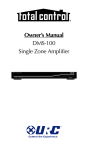
DMS-100 Owner's Manual
DMS-100 Owner’s Manual ©2010 Universal Remote Control, Inc.
The information in this manual is copyright protected. No part of this manual
may be copied or reproduced in any form without prior written consent
from Universal Remote Control, Inc.
UNIVERSAL REMOTE CONTROL, INC. SHALL NOT BE LIABLE FOR OPERATIONAL, TECHNICAL OR EDITORIAL ERRORS/OMISSIONS MADE IN
THIS MANUAL.
The information in this manual may be subject to change without prior
notice.
URC - Control the Experience is a registered trademark of Universal Remote
Control, Inc.
All other brand or product names are trademarks or registered trademarks
of their respective companies or organizations.
Universal Remote Control,Inc.
500 Mamaroneck Avenue, Harrison, NY 10528
Phone: (914) 835-4484 Fax: (914) 835-4532
TABLE OF CONTENTS
Congratulations!
2
Features and Benefits
3
Parts Guide
3
Front Panel Description
4
System Features
5
Rear Panel Description
6
USA Limited Warranty Statement
10
Specifications
12
System Configuration for Internal LAN Network
13
Europe Certificate Of Conformity
14
Page 1
DMS-100 SINGLE ZONE AMPLIFIER
Congratulations!
You’ve purchased the finest music distribution system available
today. The DMS-100 is a native to the network, CD quality digital
music distribution system with an available range of keypads and
remote controls that not only fully control your music but control
all of your other audio video components.
The DMS-100 distributes music to your speakers and other DMS
components in the system. This makes your system scalable, and
easy to add additional rooms at any time in the future. All you need
is a DMS amplifier connected to the network to make any room a
new DMS Music Room.
The DMS-100 is designed for professional installation only.
Your installer will help you select the right user interface for every
room of your installation. You’ll have a choice of Total Control inwall keypads and remote controls.
If you have questions, call your installer:
Company:
Installer Name:
Contact #:
Email address:
The customer service center is also available for any questions
you may have. Contact us at:
1-914-835-4484
or email us at:
[email protected]
Page 2
DMS-100 SINGLE ZONE AMPLIFIER
Features and Benefits
• One audio input streams to other Total Control amplifiers.
• Preamp output for connection to local amplifier.
• Scalable solution; install as an additional zone with a
DMS-1200 system, or install multiple DMS-100s to create
customized multi-zone system.
• 50 Watts per channel amplifier for speakers.
• Can be programmed off premises via the internet and
MRX-10.
Parts Guide
The DMS-100 Single Zone Amplifier includes:
1 - DMS-100 Single Zone Amplifier
1 - Ethernet Cable
Page 3
1 - Power Cord
1 - Installation Manual
DMS-100 SINGLE ZONE AMPLIFIER
Front Panel Description
Power and LAN LEDs
LEDs indicate that the DMS-100 is connected to
power and to the local area network.
Automatic Power Off
The DMS-100 is powered off and is in an automatic
stand by state when no zones are active.
Reset Button
The front panel reset button offers the end user a quick way to
reconnect the DMS-100 to the local area network.
Page 4
DMS-100 SINGLE ZONE AMPLIFIER
System Features
Pristine Audio Quality
Unlike other digital music systems, the DMS system streams
all music uncompressed at pure CD quality levels. You enjoy all
the detail of your original source.
Room Linking
Any room can be linked with any other room to listen to the same
source. This makes it easy for you to entertain by simply linking all
the rooms your guests will be in and controlling the music from any
remote or keypad.
Reliability
The DMS-100 is engineered first and foremost for reliability.
It offers extensive internal protection against failure and is manufactured in our ISO 9000 certified factory with the utmost attention to
quality control at every stage of manufacturing, from parts procurement to final assembly.
Page 5
DMS-100 SINGLE ZONE AMPLIFIER
Rear Panel Description
110V-220V Power Connection
The IEC power socket enables either UL/CSA approved
110V power cords or CE approved 220V power cables to
be used with the DMS-100. The internal power supply
automatically switches from 110V to 240V.
Network Connection
A 10/100 LAN connection ensures that the DMS-100 will
receive all network streams from other DMS or SNP sources.
IR In for 1-Way RF Remotes and Base Stations
When connected to a URC RF base station, a one-way URC
remote control can be programmed to control a zone.
Page 6
DMS-100 SINGLE ZONE AMPLIFIER
System Features
Analog Audio Input
Connect a music source to the DMS-100 to listen locally to
an AV receiver.
Preamp Zone
The preamp zone enables use of external power amplifiers
for a room with a need for more or less power than 50
watts per channel.
Speakers
The DMS-100 internal amplifier powers a pair of 8 ohm
speakers with 50 watts per speaker. The speakers can deliver
output from any DMS source.
Page 7
IMPORTANT SAFETY INSTRUCTIONS
Important Safety Instructions
This unit shall be connected to a mains socket outlet with a protective
grounded connection or equivalent.
CAUTION:
To completely disconnect this product from the mains, disconnect the
plug from the wall socket outlet. The mains plug is used to completely
interrupt the power supply to the unit and must be within easy access
by the user.
CAUTION:
These servicing instructions are for use by qualified service personnel only.
To reduce the risk of electric shock, do not perform any servicing other than
that contained in the operating instructions unless you are qualified to do
so or equivalent.
Page 8
IMPORTANT SAFETY INSTRUCTIONS
Important Safety Instructions
1.
2.
3.
4.
5.
6.
7.
8.
9.
10.
11.
12.
13.
14.
15.
Read these instructions.
Keep these instructions.
Heed all warnings.
Follow all instructions.
In the event of malfunction, un plug lmmediately.
Do not use this apparatus near water.
Clean only with dry cloth.
Do not block any ventilation openings.
Install in accordance with the manufacturer’s instructions.
Do not install near any heat sources such as radiators, heat registers,
stoves, or other apparatus(including amplifiers) that produce heat.
Do not defeat the safety purpose of the polarized or grounding-type plug.
A polarized plug has two blades with one wider than the other.
A grounding type plug has two blades and a third grounding prong.
The wide blade or the third prong are provided for your safety.
If the provided plug does not fit into your outlet, consult an electrician for
replacement of the obsolete outlet.
Protect the power cord from being walked on or pinched particularly at
plugs, convenience receptacles, and the point where they exit from the
apparatus.
Only use attachments/accessories specified by the manufacturer.
Use only with the cart, stand, tripod, bracket, or table
specified by the manufacturer, or sold with the apparatus.
When a cart is used, use caution when moving the
cart/apparatus combination to avoid injury from
tip-over.
Unplug this apparatus during lightning storms or when
unused for long periods of time.
Refer all servicing to qualified service personnel.
Servicing is required when the apparatus has been damaged in any way,
such as power-supply cord or plug is damaged, liquid has been spilled or
objects have fallen into the apparatus, the apparatus has been exposed to
rain or moisture, does not operate normally,or has been dropped.
CAUTION:
The ventilation should not be impeded by covering the ventilation
openings with items, such as newspapers, tablecloths, curtains,
etc.
No naked flame sources, such as lighted candles, should be
placed on the unit.
Minimum distances around the apparatus for sufficient
ventilation : 20centimeter
This product is use in moderate climates.
Do not expose the unit to dripping or splashing fluids, do not
place objects filled with liquids, such as vases, on the unit.
Page 9
USA WARRANTY
USA Limited Warranty Statement
Your Universal Remote Control, when delivered to you in new condition, is warranted against defects in materials or workmanship as
follows: UNIVERSAL REMOTE CONTROL, INC. warrants this product against defects in material or workmanship for a period of one
(1) year and as set forth below. Universal Remote Control will, at its
sole option, repair the product using new or comparable rebuilt
parts, or exchange the product for a comparable new or rebuilt
product. In the event of a defect, these are your exclusive remeies.
This Limited Warranty covers only the hardware components packaged with the Product. It does not cover technical assistance for
hardware or software usage and it does not cover any software
products whether or not contained in the Product; any such software is provided "AS IS" unless expressly provided for in any
enclosed software Limited Warranty.
To obtain warranty service, you must deliver the product, freight
prepaid, in its original packaging or packaging affording adequate
protection to Universal Remote Control at the address provided in
the Owner's Manual. It is your responsibility to backup any macro
programming, artwork, software or other materials that may have
been programmed into your unit. It is likely that such data, software, or other materials will be lost during service and Universal
Remote Control will not be responsible for any such damage or
loss. A dated purchase receipt, Bill of Sale, Installation Contract or
other verifiable Proof of Purchase is required. For product support
and other important information visit Universal Remote Control's
website: http://www.UniversalRemote.com or call the Customer
Service Center (914) 835-4484.
This Limited Warranty only covers product issues caused by defects
in material or workmanship during ordinary consumer use. It does
not cover product issues caused by any other reason, including but
not limited to product issues due to commercial use, acts of God,
third-party installation, misuse, limitations of technology, or modification of or to any part of the Universal Remote Control product.
This Limited Warranty does not cover Universal Remote Control
products sold as USED, AS IS, REFURBISHED, so-called “B STOCK”
or consumables (such as batteries). This Limited Warranty is invalid
if the factory-applied serial number has been altered or removed
from the product. This Limited Warranty is valid only in the United
States of America. This Limited Warranty specifically excludes
products sold by unauthorized resellers.
Page 10
USA WARRANTY
LIMITATION OF REMEDIES
UNIVERSAL REMOTE CONTROL SHALL NOT BE LIABLE FOR ANY
INCIDENTAL OR CONSEQUENTIAL DAMAGES FOR BREACH OF
ANY EXPRESS OR IMPLIED WARRANTY OR CONDITION ON
THIS PRODUCT. IN NO EVENT SHALL UNIVERSAL REMOTE
CONTROL BE LIABLE, WHETHER IN CONTRACT OR IN TORT
(INCLUDING NEGLIGENCE) FOR DAMAGES IN EXCESS OF THE
PURCHASE PRICE OF THE PRODUCT, ACCESSORY OR SOFTWARE, OR FOR ANY INDIRECT, INCIDENTAL, SPECIAL OR CONSEQUENTIAL DAMAGES OF ANY KIND, OR LOSS OF REVENUE
OR PROFITS, LOSS OF BUSINESS, LOSS OF INFORMATION OR
DATA, SOFTWARE OR APPLICATIONS OR OTHER FINANCIAL
LOSS ARISING OUT OF OR IN CONNECTION WITH THE ABILITY
OR INABILITY TO USE THE PRODUCTS, ACCESSORIES OR SOFTWARE TO THE FULL EXTENT THESE DAMAGES MAY BE DISCLAIMED BY LAW.
EXCEPT TO THE EXTENT PROHIBITED BY APPLICABLE LAW,
THERE IS NO OTHER WARRANTY EXPRESSED OR IMPLIED. UNIVERSAL REMOTE CONTROL WILL NOT BE HELD RESPONSIBLE
FOR STATEMENTS MADE BY OTHERS CONCERNING THE MERCHANTABILITY OR FITNESS FOR A PARTICULAR PURPOSE ON
THIS PRODUCT. Some states or jurisdictions do not allow the
exclusion or limitation of incidental or consequential damages, or
allow limitations on how long an implied warranty lasts, so the
above limitations or exclusions may not apply to you. This Limited
Warranty gives you specific legal rights and you may have other
rights which vary from state to state or jurisdiction to jurisdiction.
REV020708
Page 11
SPECIFICATIONS
Specifications
Network
One 10/100 Ethernet port
(Indicator Two LED)
IR One Way & IP Two Way
Control:
Yes
Indicators:
One Power Blue LED - Blink
when resetting/One Network
Blue LED indicator
Zones of Stereo Audio:
One (preamp and speaker
output are linked)
Rated Wattage per Channel:
50 watts per channel at 8
ohms, stable to 4 ohms
Automatic Low Volume
Loudness Compensation:
Installer configured for type
and size of audio zone
Installer Configured EQ:
Bass Boost, Treble Boost,
5-Band parametric EQ
Input Sensitivity:
600~2200mVp-p / 10Kohm
User Adjustable
Audio Controls:
Bass, Treble and Balance
Receives all SNP and DMS
Generated Streams:
Yes
Inputs:
One Stereo Line input streams
to all other DMS Amplifiers
Preamp Output:
Yes, configurable to Fixed Line
Level Output
Power Supply:
AC100~245V, 50/60Hz
Power Consumption:
1~2A
Maximum external
Dimensions:
1.7” x 17” x 8.7” (H X W X D)
Weight:
7lbs (3.2Kg)
Page 12
DMS-100 SYSTEM CONFIGURATION
System Configuration for Internal LAN Network
Cable Modem
Internet
WiFi Router
MFS-8
DMS-100
PC
Follow the steps below to connect a DMS-100 to a LAN network.
1. Connect the Internet to the coaxial CABLE port in the rear of the
cable modem.
2. Plug in a RJ-45 ethernet connector cable via the Ethernet port of
the cable modem to the WAN port of the Router.
3. Connect a second RJ-45 cable to a LAN port of the Router and
plug the other end to the LAN 10/100 port on the rear of the
MFS-8/MFSPOE-8 network Switch.
4. Connect a third RJ-45 cable to connect the DMS-100 LAN port to
one of the eight 10/100 Smart ports.
5. Plug the power supply to the DMS-100 and then plug it in to an
unswitched AC outlet.
6. Connect a PC computer to the same LAN (WLAN) as the DMS-100
or plug an ethernet cable directly to the LAN port of the DMS-100.
Now the computer can control and adjust the manufacturer’s audio
control program.
Select audio INPUT source and OUTPUT zone, MAC address etc.
This function selects input source channel and INPUT gain level
and data sent to audio equipment.
After selecting the output zone, adjust the zone limit power rate and
zone power ON/OFF and source signal INPUT channel.
Adjust the amplifier volume level per each zone for proper sound
output and maximum limitation volume level.
Turn on the ramp up volume level and adjust the equalizer repertory
and low volume loudness control effectiveness and custom equalizer align.
Page 13
EUROPE CERTIFICATE OF CONFORMITY
Europe Certificate Of Conformity
Universal Remote Control, Inc. declares that this product complies with
the requirements CE/LVD (Low Voltage Directive, 2006/95/EC).
Certificated Attestation of compliance “E8N 10 10 75224 001” is issued
according to the Directive 2004/108/EC relating to electromagnetic
compatibility on a voluntary basis and is in compliance with the corresponding technical standards such as EN55013, EN55020, EN55022,
EN55024/A2, EN61000-3-2, EN61000-3-3 and EN60065 A/V. A copy
of the full Certificate of Conformance may be obtained at
“http://www.universalremote.com”
Page 15
NOTE
Page 16
NOTE
Page 17
Page 16
OCE-0099C Rev 01