1
Thermal Label Printing Scale
LP - II
Service Manual
Version 3.0
Attention:
Copyright© 2006, by CAS Corporation. All rights reserved. No part of this publication may be
reproduced, transmitted, transcribed, stored in a retrieval system, or translated into any
language or computer language, in any form or by any means, electronic, mechanical,
magnetic, optical, chemical, manual or otherwise, without the prior expressed written permission
of this company.
Disclaimer:
This company makes no representations or warranties, either expressed or implied, with respect
to the contents hereof and specifically disclaims any warranties of merchantability or fitness for
any particular purpose. Any software describes in this manual is sold or licensed “as is”. Should
the programs prove defective following their purchase, the buyer (and not this company, its
distributors, or its dealers) assumes the entire cost of all necessary servicing, repair, and any
incidental or consequential damages resulting from any defect in the software. Further, this
company reserves the right to revise this publication and to make changes from time to time in
the contents hereof without obligation to notify any person of such revision or changes.
Brand and product names are trademarks and/or registered trademarks of their respective companies.
Table of Contents
1 General
1.1
1.2
1.3
Introduction ............................................................................................................................ 1
Model and Specifications.................................................................................................... 2
Dimensions.............................................................................................................................. 3
2 Unpacking and Assembly
2.1
2.2
Unpacking .............................................................................................................................. 4
Assembly of DisplayColumn ................................................................................................ 5
3 Proper Operation
3.1
3.2
3.3
Environmental Considerations and Safety........................................................................ 6
Leveling and Location.......................................................................................................... 7
Power Outlet and Requirements ........................................................................................ 8
4 Nomenclature
4.1
4.2
4.3
4.4
4.5
Scale Overview...................................................................................................................... 9
Display and Indicators ........................................................................................................ 10
Printer..................................................................................................................................... 11
The Program Mode Numeric Keypad.............................................................................. 12
The Program Mode PLU Keypad ...................................................................................... 14
5 Getting Started
5.1
5.2
Installation of the Label Roll............................................................................................... 16
Menu and Data Entry System............................................................................................ 18
6 Calibration Mode
6.1
6.1A
Entering Calibration Mode ................................................................................................ 20
Entering Calibration Mode (alternate method) ............................................................ 20
7 Calibrating the Scale Warranty Info
7.1
7.2
7.3
7.4
Calibration Menu ................................................................................................................ 21
Span Calibration ................................................................................................................. 21
Span/Zero Find Adjust......................................................................................................... 22
Gravity Constant ................................................................................................................. 23
8 System Options
8.1
8.1.1
8.1.2
8.1.3
8.1.4
8.2
8.2.2
8.3
8.4
8.5
8.6
8.7
Weight Options .................................................................................................................... 25
Capacity & Units.................................................................................................................. 25
Tare Options ......................................................................................................................... 26
Zero Range ........................................................................................................................... 26
Captions & Headings ......................................................................................................... 27
Non-Weight Options ........................................................................................................... 29
Auto Print Threshold ............................................................................................................ 29
Report Settings ..................................................................................................................... 30
Decimal Place Setting ........................................................................................................ 29
Keypad Options................................................................................................................... 30
Clear Memory ...................................................................................................................... 31
Select country ...................................................................................................................... 32
9 Digital Filtering
9.1
Digital Filter Settings............................................................................................................. 33
ii
10 Printer Hardware Settings
10.1
10.2
10.2.1
10.2.2
10.2.3
10.3
10.4
10.5
10.6
10.7
10.8
Printer Hardware Settings Menu ....................................................................................... 34
Printer Sensors ...................................................................................................................... 34
Gap/Peel Calibrate............................................................................................................ 34
Gap Sensor Fine Adjust ...................................................................................................... 35
Peel Sensor Fine Adjust....................................................................................................... 35
Print Speed ........................................................................................................................... 35
Printer Odometer ................................................................................................................ 36
Label Type ............................................................................................................................ 36
Feed Adjust .......................................................................................................................... 38
Auto Threshold ..................................................................................................................... 38
Report Settings..................................................................................................................... 38
11 Networking
11.1
Setting Up a Network.......................................................................................................... 39
12 Self Test Mode
12.1
12.2
12.3
12.4
12.5
12.6
12.7
12.8
12.9
12.10
Self Test Menu ...................................................................................................................... 41
Display Test ........................................................................................................................... 41
Load Cell Test....................................................................................................................... 41
Keyboard Test ...................................................................................................................... 42
Printer Test............................................................................................................................. 43
Peel Off Test ......................................................................................................................... 44
Memory Size ......................................................................................................................... 44
NV Memory Test................................................................................................................... 44
Serial Port Test ...................................................................................................................... 45
Firware Versions Test ........................................................................................................... 45
13 Audit Trails
13.1
Reading Audit Trail Counters ............................................................................................ 46
14 Servicing and Parts Replacement
14.1
14.2
14.3
14.4
14.5
14.6
14.7
14.7.1
14.7.2
14.7.3
14.7.4
14.7.5
14.7.6
14.7.7
14.8
14.9
14.10
Platform Safety Overload Adjustment ............................................................................ 47
Removing the Upper Case................................................................................................ 47
Main PCB Replacement .................................................................................................... 49
Network Board Replacement........................................................................................... 50
Power Supply Replacement ............................................................................................. 50
Load Cell and A/D Converter Replacement................................................................. 51
Printer Assembly Replacement......................................................................................... 51
Rewind Motor Assembly Replacement........................................................................... 52
Stepper Motor Assembly Replacement.......................................................................... 52
Thermal Print Head Replacement.................................................................................... 53
Gap Sensor Assembly Replacement............................................................................... 53
Peel Sensor Assembly Replacement ............................................................................... 53
Label Roll Spool Replacement ......................................................................................... 54
Width Adjuster Replacement............................................................................................ 54
Display Replacement ......................................................................................................... 54
Keyboard Replacement.................................................................................................... 54
Keyboard Servicing............................................................................................................. 55
iii
15 Installing Options
15.1
15.2
Installing the Network Memory Card ............................................................................... 56
Installing the Paper Cutter ................................................................................................. 56
16 Troubleshooting
16.1
16.2
Troubleshooting Chart ........................................................................................................ 57
Additional Errors ................................................................................................................... 59
17 Diagrams
17.1
17.2
17.3
17.4
17.5
17.6
17.7
System Block Diagram ........................................................................................................ 60
Connection Diagram ......................................................................................................... 61
Main PCB ................................................................................................................ Fold-out 1
Network PCB .......................................................................................................... Fold-out 2
Power Supply PCB ................................................................................................. Fold-out 3
Scale Exploded View............................................................................................ Fold-out 4
Printer Assembly Exploded View......................................................................... Fold-out 5
18 Part's List
18.1
18.1.1
18.1.2
18.1.3
18.1.4
18.1.5
18.1.6
18.1.7
18.1.8
18.1.9
18.1.10
18.1.11
18.2
18.2.1
18.2.2
18.2.3
18.2.4
18.2.5
18.2.6
18.3
18.3.1
18.3.2
18.3.3
18.3.4
18.3.5
18.3.6
18.3.7
Electrical ............................................................................................................................... 62
Ethernet Memory Optional Board Ass'y........................................................................... 62
Peel Off Sensor PCB Ass'y ................................................................................................... 62
Ethernet Option Board Ass'y .............................................................................................. 63
Analog Module Ass's........................................................................................................... 63
Analog PCB Ass'y................................................................................................................. 64
BodyAss'y .............................................................................................................................. 64
Main PCB Ass'y ..................................................................................................................... 65
Cal PCB Ass'yl ....................................................................................................................... 66
Display PCB Ass'y ................................................................................................................. 66
AP Sensor PCB Ass'y ............................................................................................................ 67
Key PCB Ass'y ....................................................................................................................... 67
Mechancal........................................................................................................................... 67
Upper Case Ass'y................................................................................................................. 67
Display Case Ass'y ............................................................................................................... 68
Body Ass'y ............................................................................................................................. 68
L/C Brackey Ass'yl................................................................................................................ 69
POT Ass'y ............................................................................................................................... 69
Front Cover Ass'y ................................................................................................................. 69
Mechanism........................................................................................................................... 69
TPH Ass'y ................................................................................................................................ 69
Main Bracket Ass'y............................................................................................................... 70
Rewinder Ass'y...................................................................................................................... 70
Paper Guide Ass'y ............................................................................................................... 71
Stepping Motor Ass'y .......................................................................................................... 71
Roll Bracket Ass'y ................................................................................................................. 71
C/T Box Ass'y......................................................................................................................... 71
Appendix A: Country Codes.......................................................................................... 62
Appendix B: Label Formats ............................................................................................ 63
iv
CAS (USA) CORPORATION
LIMITED WARRANTY
CAS (USA) Corporation (“CAS”) warrants to the first end user customer of the CAS product enclosed with this limited warranty statement,
that the product if purchased and used in the United States or Canada, conforms to the manufacturer’s specifications and will be free from
defects in workmanship and materials for a period indicated on the space provided on the bottom of this form from the date of original
purchase or three months after product is shipped from CAS to the CAS Authorized Dealer, which ever comes first. CAS warrants that the
CAS product is manufactured from new components and parts or like-new components and parts which perform like new and meet the CAS
standard of quality. And only on CAS printing products, CAS also warrants that the consumable labels enclosed will perform to the
manufacturer’s specific usage, which usage may expire before the expiration of the limited warranty for the CAS product.
Should your CAS product prove defective during the warranty period, please contact the CAS Dealer from which you purchased the CAS
product, or call the CAS Service Hot line at (201) 933-9002 for warranty repair instructions and return authorization, if required. CAS or a
CAS Authorized Service Center will, at their option, repair or replace on an exchange basis the defective unit, without charge for parts or
labor. When warranty service involves the exchange of the product or of a part, the item replaced becomes CAS property. The exchanged
product or part may be new or previously repaired to the CAS standard of quality. Exchange or replacement products or parts assume the
remaining warranty period of the product covered by this limited warranty.
This warranty covers only normal consumer use in the United States and Canada. This warranty does not cover labels or third party parts,
components or peripheral devices added to the CAS product after its shipment from CAS, e.g., the dealer-added boards or chips, or the
accuracy of the product after it is shipped from CAS. CAS is not responsible for warranty service should the CAS label or logo or the rating
label or serial number be removed or tampered with or should the product fail to be properly maintained or fail to function properly as a result
of misuse, abuse, improper installation, neglect, improper shipping, damage caused by disasters such as fire, flood, and lightning, improper
electrical current, software problems, interaction with non-CAS products, or service other than by CAS or a CAS Authorized Service Center.
Packaging and shipping cost to and from the CAS repair facility will be CAS’s responsibility. If a claimed defect cannot be identified or
reproduced in service, you will be held responsible for costs incurred.
THE WARRANTY AND REMEDY PROVIDED ABOVE ARE EXCLUSIVE AND IN LIEU OF ALL OTHER
EXPRESS OR IMPLIED WARRANTIES INCLUDING, BUT NOT LIMITED TO, THE IMPLIED WARRANTIES OF
MERCHANTABILITY OR FITNESS FOR A PARTICULAR PURPOSE. SOME LAWS DO NOT ALLOW THE
EXCLUSION OF IMPLIED WARRANTIES. IF THESE LAWS APPLY, THEN ALL EXPRESS AND IMPLIED
WARRANTIES ARE LIMITED TO THE WARRANTY PERIOD IDENTIFIED BELOW. UNLESS STATED HEREIN,
ANY STATEMENTS OR REPRESENTATIONS MADE BY ANY OTHER PERSON OR FIRM ARE VOID. EXCEPT
AS PROVIDED IN THIS WRITTEN WARRANTY, NEITHER CAS (USA) CORPORATION NOR ITS AFFILIATES
SHALL BE LIABLE FOR ANY LOSS, INCONVENIENCE, LOSS OF ANY DATA OR PROGRAMMING, OR
DAMAGE, INCLUDING DIRECT, SPECIAL, INCIDENTAL, OR CONSEQUENTIAL DAMAGES, RESULTING
FROM THE USE OR INABILITY TO USE THE CAS PRODUCT, WHETHER RESULTING FROM BREACH OF
WARRANTY OR ANY OTHER LEGAL THEORY.
In Canada, warranties include both warranties and conditions.
Some jurisdictions do not allow limitations on how long an implied warranty lasts and some jurisdictions do not allow the
exclusion or limitation of incidental or consequential damages, so the above limitations and exclusions may not apply to you.
This warranty gives you specific legal rights, and you may have other rights that may vary from jurisdiction to jurisdiction.
This warranty applies ONLY to the LP-Series label printing scales.
WARRANTY PERIOD: 1 (ONE) YEAR
To locate the CAS Authorized Dealer or CAS Authorized Service Center nearest you call:
(201) 933-9002
or write to:
CAS (USA) Corporation • 99 Murray Hill Parkway • East Rutherford, NJ 07073
1 General
1.1
Introduction
Thank you for purchasing the CAS LP-2 price computing electronic printing scale. We have designed
this equipment with many advanced features, high quality construction, and user-friendly menu driven
programming. We are confident that you will find the CAS LP-2 scale will meet all of your most
demanding needs.
Sales data is easily acquired through many of the available reports which are quickly accessible
through the on-screen menus. This scale comes complete with enhanced standard features including:
4 inch per second printing speed, 53 preset keys (106 using the SHIFT key), and several operation modes
that enable you to control & limit access to the scale for increased security.
Communication is another powerful feature of the LP-II. It comes with an RS-232 port, which can tie a
scale to a personal computer (P.C.) for exporting or importing program data. Because PLU and all
other data files are kept locally in each scale’s RAM memory, the scale’s speed is the same in a network
setting or as a stand-alone unit. For larger operations, there is an in-store network that can have up to
99 scales, connected via Ethernet cables or an optional wireless bridge.
The LP-2 can be easily used with a wide variety of industry standard thermal labels. By simply entering a
label’s length and width dimensions, you can use practically any of them on the LP-2! You can also use
continuous strip labels or even thermal paper. You also can print logos, templates, Nutri-Facts panels,
ingredient messages, advertisement lines, and more.
Remember, for proper installation and maintenance please refer to the LP-2 Service Manual. A wide
variety of supplies and accessories are available through CAS (USA) Corporation for whatever your new
and increasing demands may require. Before attempting any repairs or servicing please look over this
manual carefully or contact CAS (USA) Corp.
The LP-2 also comes with an enhanced version of our popular software package. This software
runs on any PC using the Windows® 98/2000/XP operating system. You can design your own label
formats on your computer screen and download them to the scale or save them on your hard drive.
The labels you see on-screen appear exactly “as they will print.” You can also manage all of the LP-2’s
programs and options like pricing, PLU programming, etc. You can upload data from an LP-2 to a PC or
transmit data from one scale to another, perfect as an emergency backup system. All this and many
more features are packed into the LP-2 software package. This makes the LP-2 software package an
indispensable commodity for your business.
To find the Authorized CAS Dealer nearest you, please visit our web-site at www.cas-usa.com.
1
1 General
1.2
Model and Specifications
MODEL
CHARACTERS PER PLU
DISPLAYS
GENERAL
PROGRAMMABLE DATA
INTERFACES
LABEL SIZES
MAX TARE
MEASUREMENT TYPE
MEMORY CAPACITY
NETWORK
SPECIFICATIONS
OPERATING TEMP.
PLU PROGRAMMABLE
DATA
PLATTER SIZE
POWER SOURCE
PRINT SPEED
PRINTER TYPE
SALES PERIODS
SALES REPORT MODES
SALES REPORT TYPES
SHIPPING WEIGHT
WEIGHING CAPACITY
WEIGHING RANGE
WEIGHING UNITS
LP-2, (version 2.23)
Ingredients: 2000 characters, PLU Name: 114 characters
WEIGHT: 5 digits
(5 max)
UNIT PRICE: 6 digits
(8 max)
TOTAL PRICE: 7 digits
(9 max)
Users/Clerks : 99 @ 20 Char
Scrolling Messages : 32 @ 80 Char
Label Formats : 999 @ 30 Char
Sales Messages
: 32 @ 40 Char
Label Formats : Over 50 Built-In
Store Name
: 150 Char
Origin
: 400 @ 25 Char
Departments
: 32 @ 20 Char
RS-232 Serial Ports: COM1 (9 pin female), COM2 (25 pin female), Ethernet
Width: 10mm~80 mm (0.40 in.~3.15 in.)
Length: 20mm~170 mm (0.94 in.~6.69 in.)
Length: 850 mm (33.46 in.) max length using linked formats.
FULL CAPACITY
LOAD CELL
Over 4000 PLUs
4 Mbps Network Specifications
99 Scales MAX
Wireless Ethernet (optional wireless bridge
99 Clerks MAX
required)
100m (0.06 miles) max cable length
-10° C~ 40° C (14° F~ 104° F)
Tare Weight
: 0~Capacity
Department #
: 1~32
Price
: 0.00~9999.99
PLU #
: 1~999999
Sale Weight
: 0~Capacity
Commodity Name
: 114 Char
Sale Price
: 0.00~9999.99
Label Format #
: 1~999
Net Weight
: 0~99999
Sales Message #
: 1~32
Count
: 1~99
Unit
: lb, kg
Sale Count
: 0~99
Group Code
: 0~99
UPC
: 0~999999
Tax Rates
: 0~3
Ingredients
: 2000 Char
Country Code
: 0~999
Barcode Type/Format
Sell By Date
: 0~999 days
Nutritional Information
Cook By Date
: 0~999 days
Frequent Shopper/Discount Information
Length: 403 mm (15.87 in.), Width: 260 mm (10.24 in.)
85~240VAC 50/60Hz ±5%
100 mm/sec (4 in./sec)
DIRECT THERMAL PRINT
Dual totals for daily/monthly or user selectable reporting periods.
Read: X1/X2 Modes, Read & Reset: Z1/Z2 Modes
Clerk Report
Monthly PLU & Misc. PLU Report
Daily PLU & Misc. PLU Report
Monthly Department Report
Daily Department Report
Monthly Scale Report
Daily Scale Report
Monthly Group Report
Daily Group Report
Monthly Hourly Report
Daily Hourly Report
Monthly Detailed Report
Daily Detailed Report
13 kg (29 lb)
0~15 x 0.005 lb/ 0~30 x 0.01 lb, 0~30 x 0.01 lb / 30~60 x 0.02 lb
(0~3x0.001kg/3~6x0.002kg, 0~6 x 0.002 kg / 0~15 x 0.005 kg,
0~15 x 0.005 kg / 15~30 x 0.01 kg)
DUAL RANGE
Pound & Kilo push-button selectable.
Note: Specifications are subject to change without notice.
2
1 General
1.3 Dimensions
3
2 Unpacking and Assembly
2 Unpacking and Assembly
2.1 Unpacking
#
1
2
3
4
5
6
7
8
9
10
11
12
13
14
15
16
17
18
Description
Desiccant, silica bag
LP-2, Display assembly
LP-2, Display assembly screws
LP-2, Scale body
Owner’s Manual, LP-2
Packing box
Packing lid
Plastic bag, display column
Plastic bag, scale
Fuse
Platter
SP-2 software package
Thermal labels, 1 roll (installed)
Top form-fitted packing foam
Bottom form-fitted packing foam
Manual plastic bag
Fuse Plastic bag
PLU pad
4
QTY
3
1
2
1
1
1
1
2
1
1
1
1
1
1
1
1
1
1
2 Unpacking and Assembly
2.2
Assembly of Display Column
1)
You must follow the instructions in this section in order to assemble the Display Assembly properly.
To begin the installation, make sure that the scale is unplugged from any electrical source. Your scale
body has a display column bracket in the rear that the display column slides into. (See fig.)
2)
Hold the display assembly in front of you such that the display assembly forms the figure “7”.
Next, with the scale’s keyboard facing you, insert the display column into the display bracket. When the
display column reaches the bottom of the display bracket, you will “feel” the connectors “snap”
together. (See fig.)
3)
Underneath the display bracket you will find 2 screw holes for the display assembly screws. Insert
and fasten the 2 display assembly screws. You are done! (See fig.)
5
3 Proper Operation
3 Proper Operation
3.1 Environmental Considerations & Safety
1) Please avoid the following hostile conditions:
Temperatures below or exceeding:
-10º C ~ 40º C (14º F ~ 104º F)
Excessive vibration
Wind or fans functioning in direct
contact with weighing platform.
Direct sunlight
High humidity
Ungrounded electrical outlet
Unstable or flimsy surface
Shared electrical outlet
Dust or dirt
Poor ventilation
2) Environmental Protection: The scale should be installed in a dry and liquid free environment. When
the scale is installed in a high humidity or wet-type environment, be sure to avoid spilling or spraying
directly on any surface of the scale.
3) Personal Safety: It is extremely important to be aware of personal safety whenever maintaining or
operating this equipment. Wherever possible, we have tried to place warning labels and other
indicators at the actual location on the equipment where the danger is most likely to occur. However, it
is not always possible to foresee all dangerous situations. Warnings and cautions that are necessary for
the safe operation of the scale are contained in this manual. Please, make sure to carefully read ALL
warnings and cautions before operating the scale.
4) Observe the following safety precautions:
Shut the scale OFF and unplug the scale whenever you are changing the label
roll or whenever working in the printer bay.
The outlet that the scale is plugged in to should be properly grounded.
Whenever connecting or disconnecting ANY cables from the scale, be sure to
hold the cables by the end connector. Failure to do so may cause a short circuit.
Maintain a static free work area.
Never use any other equipment on the same line: it should be a dedicated line.
The outlet used must have the proper voltage ratings.
6
3 Proper Operation
3.2
Leveling and Location
1) Location: This scale must be placed on a flat and stable surface. Please keep the scale away from
the direct path of oscillating fans, ventilation systems, or strong drafts as these air disturbances can be
picked-up by the scale’s very sensitive weighing platform and may cause incorrect weight readings.
2) Leveling: If the scale is not properly leveled, please adjust the 4 adjustable legs at the bottom of
the scale. Turn the legs clockwise or counterclockwise so as to center the bubble of the leveling gauge
inside the indicated circle. Turning the adjustable legs counter-clockwise (viewed from top of scale) will
lower that part of the scale. Turning the adjustable legs clockwise (viewed from top of scale) will raise
that part of the scale. (See Fig.)
7
3 Proper Operation
3.3
Power Outlet and Requirements
1) The LP-2 is designed to be used almost anywhere in the world! Like the many appliances of today,
the LP-2 is designed with an automatically switching power supply. This allows operation when
connected to an AC source from 85V to 240V at 50/60Hz with 5% tolerance.
Remember: a switching power supply does not imply that bad, noisy, or improperly wired power lines
will be problem free. With that in mind, please make sure that the power lines used for the LP-2 are
dedicated lines with no high-noise devices (such as compressors, motors, etc) running on it. Also, make
sure that the wiring to the electrical socket is correct. If you are uncertain as to the state of your
business’ electrical lines, please contact a certified electrician.
2) Once you are sure as to the safety of the electrical line, make sure to ONLY plug the scale into a 3prong outlet. The third prong is a safety ground and an electrician should properly wire this if it is not
correct or if you are unsure. Failure to this CAN result in electrical shock from use of this or any electronic
scale.
3) Do not use any 3-prong to 2-prong adapters or break-off the third prong from the LP-2 power cord.
The third prong is necessary and must be properly connected.
4) If you have any problems or questions regarding this matter, make sure to contact your authorized
dealer or the CAS USA Service Department.
Note: Be sure to check the LP-2’s serial number plate on the back of the scale for power specifications.
8
4 Nomenclature
4 Nomenclature
4.1 Scale Overview
1) Pictured below are important scale components and parts that you should be familiar with.
#
1
2
3
4
5
6
7
8
Description
Advertisement Insert, rear
Wireless Bridge Connector
RS-232C 25 Pin Connector
RS-232C 9 Pin Connector
Ethernet Connector
Display Column
Display Window, customer
Display Window, user
#
9
10
11
12
13
14
15
Description
Fuse Cap
Gauge, Leveling
Keyboard, Numeric
Keyboard, Speed Keys
Leveling Feet
Platform
Platter
9
#
16
17
18
19
20
21
22
23
Description
Power Switch
Printer
Serial Number Plate
Side Access Door, Com port
Side Access Door, printer
Template Sheet, Numeric
Template Sheet, PLU
Power Switch
4 Nomenclature
4.2
Display and Indicators
1) VF Display: The front and rear displays on the LP-2 are dot matrix vacuum fluorescent displays.
They will display all information pertinent to operating the scale.
LP-2 Display Window: Sales
1
I
17
16
15
2
3
4
5
<REG> Auto PrePack Shift Ride
6
7
12:12:00 PM
This is PLU Commodity Nam
WEIGHT kg
UNIT $ / kg
TOTAL PRICE $
ZERO ◀
STABLE ○
NET ◀
CAPACITY:
14
13
8
0~30 lb x 0.01 lb / 30~60 lb x 0.02 lb, e=d=0.01 lb, 0.02 lb
0~15 kg x 0.005 kg / 15~30 kg x 0.01 kg, e=d=5g, 10g
12
11
#
1
Description
Mode indicator
2
3
4
5
6
Print Mode indicator
Auto Clearing status indicator
Speed key Shift status indicator
Override, Frequent Shopper, &
Discount Status
Multi-function indicator
7
8
9
10
11
12
13
14
15
16
17
PLU Description line
Total price heading
Total price indicator
Unit price heading
Unit price indicator
Weight indicator
Weight heading
Negative weight indicator
Net-Weight indicator
Stable weight indicator
Zero weight indicator
10
9
Values
REG, RPK, MGR, ADD, PLU, NET1, STR2,
LOC, SET, X1, X2, Z1, Z2
Auto
PrePack, Save, (Blank)
Shift, (Blank)
Ride, FSP, DISC, Disc, 1, 2, 3, (Blank)
Time, date, scale #, department #,
Alt, Temporary Changes, (Blank)
First non-blank line of PLU commodity
TOTAL PRICE and money symbol
7 digits USA: 0.00~9999.99
UNIT, money and weigh symbols
6 digits USA: 0.00~999.99
5 digits
WEIGHT and weigh symbol
-, (Blank)
◀, (Blank)
○, (Blank)
◀, (Blank)
A Gross Zero indication is reached when the Net-Weight indicator is OFF, the Zero-Weight indicator is ON,
the Stable indicator is ON, and the weight reads 0.00 or 0.000.
10
4 Nomenclature
4.3
Printer
1) Pictured below are important printer components and parts that you should be familiar with.
#
1
2
3
4
5
6
Description
Label/Paper Roll
Label Roll Spool
Lock-Down Tab
Paper Cutter
Peel-Off Bar
Pick-Up Spool Assembly
#
7
8
9
10
11
12
Description
Platen
Pressure plate & width adjuster
Pressure shaft
Release Lever, TPH
Roller, return
Brush
11
#
13
14
15
16
17
18
Description
Sensor Assembly, Gap
Sensor Assembly, Peel-Off
Shaft, Pick-Up Motor
Side Access Door, printer
Thermal Print Head
Paper Guide Plate
4 Nomenclature
4.4
The Program Mode Numeric Key Pad
Key
0
O
P
COPY
▲
PAGE
UP
L
BACK
SPACE
◀
SAVE
▶
INSERT
OVER
DELETE
PASTE
▼
PAGE
DOWN
7
8
9
SHIFT
4
5
6
ESC
HELP
1
2
3
TEST
LABEL
FEED
00
.
0
C
ALT
ENTER
Description
~
9
00
.
Decimal key.
C
Clear key. Used to clear erroneous entries and error conditions. Also stops
multi-label printing that is in progress.
COPY
Copy key.
▲
▼
◀
▶
BACK
SPACE
Numeric keys. Used to enter programming data.
Up & Down arrow keys. Use to navigate through PGM mode.
Left & Right arrow keys. Use to navigate through PGM mode.
Backspace key. Used to backspace and delete text data.
12
4 Nomenclature
Key
Description
PAGE
UP
PAGE
DOWN
Page Up & Page Down keys. Use these to navigate 1 screen at a time.
A ~
Z
Alpha keys. Used to type text data.
INSERT
OVER
SAVE
ENTER
DELETE
PASTE
ALT
Insert/overwrite key. Used to toggle between Insert and overwrite modes for
text typing.
Save key. At any point in programming, this key saves your current data.
Enter key. Used as an ENTER key.
Delete key. Used to delete text data.
Paste key.
ALT key. This key is used for special key combination presses.
SHIFT
SHIFT key. This is the Caps Lock key. It controls whether you are typing in
uppercase .
ESC
Escape key. This key toggles between Main menu and <REG> mode. It also
is used to exit programs.
HELP
Help key.
TEST
Test key. Used to print test pattern, preview a scrolling message, and print a
PLU verification label.
LABEL
FEED
Label Feed key. Use this key to feed labels or paper through printer.
Carriage Return key. This key is used to insert Carriage Returns into the Text 1,
2, & 3 fields of PLU Create/Edit.
13
4 Nomenclature
4.5 The Program Mode PLU Key Pad
Q
W
E
R
T
Y
U
I
A
S
D
F
G
H
J
K
Z
X
C
V
B
N
M
,
,
|
\
{
[
}
]
SPACE
_
-
+
=
.
.
@
(
#
)
^
&
%
!
$
*
:
;
“
‘
?
/
À
à
È
è
Ì
ì
Ñ
ñ
Ò
ò
Ù
ù
Ü
ü
<
>
CHANGE
PRICE
NEW
PLU
EDIT
PLU
DELETE
PLU
LIST
PLUs
PROGRAM
SPEED KEYS
PRINT
TEST
ASSIGN
SCROLL
Key
Description
A
~
Z
SPACE
,
,
~
<
>
Alpha keys. Used to type text data.
Space bar.
Special Symbol keys.
CHANGE
PRICE
PLU Price Change key.
NEW
PLU
PLU Create key.
EDIT
PLU
PLU Edit key.
DELETE
PLU
PLU Delete key.
14
4 Nomenclature
Key
Description
LIST
PLUs
PLU Listing key.
PGM
SPEED KEYS
Speed Key programming key.
PRINT
TEST
Print test key.
ASSIGN
SCROLL
Scrolling message assignment key.
15
5 Getting Started
5 Getting Started
5.1 Installation of the Label Roll
To install the label roll at ANY time you must follow the directions in this section:
1) Press the ON/OFF key and make sure that the display is completely off. Open the printer’s sideaccess panel. As you can see, there is a detailed diagram affixed onto the inside of the side-access
panel. Use this diagram (or this manual) for future reference on how to properly install the label roll.
(See fig.)
2) Find and remove the Pick-Up Spool assembly and the label-roll Pin. Also, find the Print Head Release
Lever and push it in the direction indicated. The print head will be in the “UP” position. If there were any
labels previously installed please remove all the collected backing paper from the Pick-Up Spool
assembly. The Pick-Up Spool assembly automatically collapses when it is removed from the Pick-Up
shaft. This makes the removal of the backing paper very simple. Also remove the cardboard paper roll
core if there was a label roll previously installed. (See fig.)
16
5 Getting Started
3) Take the new roll of labels and find the ending. Peel-off and discard about one foot (12 inches) of
labels from the backing before installing the roll into the scale. Place the label in the scale as shown
and thread the backing through the appropriate places. (See fig.)
4) Please view the checkpoints on the diagram below as you read these directions to thread the labels.
c Feed the backing paper over the width-adjusting Pressure Shaft lifting the Pressure Plate in order to
place the backing between the two making sure that the width adjustment is as exact as possible
without bending the backing paper.
d Feed the backing paper inside the slot between the Gap sensor assembly making sure that the labels
travel under the Secondary width-adjuster.
e Make sure that labels are pushed all the way to the left on the Peel-Off bar.
f Feed the backing over the Rubber Roller and under the Print Head being careful not to touch the
underside of the Print Head.
g Continue to feed the backing paper over the Peel-off Bar.
h Continue to feed it under the Return Roller.
i Feed the backing under and around the Pick-Up Shaft.
j Now attach the Pick Up Spool assembly onto the Pick-Up Shaft and turn it slowly counterclockwise in
order to tighten the backing paper.
5) Push the Print Head down in order to lock it back in place. You will feel and hear it lock in place.
Close the printer access panel and press the ON/OFF key. You have completed the label roll installation.
(See fig.)
MAKE SURE YOU HAVE DONE
THE ADJUSTMENTS AT POINTS
1, 2, AND 3 BEFORE YOU LOCK
THE PRINT HEAD.
17
5 Getting Started
5.2 Menu and Data Entry System
To Enter Calibration Menu, hold
down the ON/OFF key while turning
on the power
The CAL Main Menu screen looks
like this:
Pressing ESC from this menu
will take you out of CAL mode and
effect all of the changes that you
may have made.
< CAL: MAIN MENU >
1.
2.
3.
4.
CALIBRATION
SYSTEM OPTIONS
DIGITAL FILTERING
PRINTER SETTINGS
5.
6.
7.
8.
NETWORK OPTIONS
SELF TEST
NORMAL FUNCTION
PRICE OPTIONS
Menus & Sub-Menus: Any menu or sub-menu screen that you access can be exited by pressing the ESC
key. This will take you back to any previous menu or sub-menu except if you press ESC from the CAL
Main Menu. The picture above is an example of a menu. Any menu that you access by selecting
options 1 to 5 will be a sub-menu of CAL Main Menu. Any menu that you access from a sub-menu will
be a sub menu of that menu, etc. This way you can always backtrack to the CAL Main Menu by
pressing the ESC.
Entry Screens: An example of an
NUMERIC
entry screen is shown here. If you
<
CAL:
SAMPLE
ENTRY
SCREEN
>
access an entry screen you can
exit it without making changes by
Unit
:[1] 0)kg
1)lb
pressing the ESC key. This will
have the effect of returning to the
Label Format (1-999):[123] LST #8020 Ingredient
previous screen, menu, or subUnit Price
:$[ 0.99] / lb
menu, whatever be the case. If
you are on an entry screen you
can save & exit that screen by
pressing the SAVE key at any point. Pressing the ENTER key while the cursor is on the last field (bottom)
of an entry screen will have the same effect as pressing the SAVE key.
Fields (on-screen): Entry screens have fields that contain data that you can modify. This data is always
contained in brackets: [123456] or [ABCDEDG
]. To select a field, simply use the ↑ or ↓ keys to
move the cursor to that field.
•
A field’s name followed by a colon will usually appear on the left side of the bracketed data. In
the Sample Entry Screen above, the word “Unit :” appears to the left of the brackets containing the
value 1. To the right of the Unit field is the options that you may select: 0 is kilograms & 1 is pounds.
These are the only two acceptable values for this field. Any values selected outside that range will
automatically replaced with values within that range.
•
The Label Format Field is slightly different. This field indicates its range in parenthesis listed after
the field’s name. In this case it is 1 to 999. Also, the data that appears to the right of the entry field
brackets changes dynamically as you type. For example, if the cursor is on the Label Format field and
you press the CLEAR key you will see that the format number will change to 1 and the name of label 1
will appear on the right side of the brackets. If you press the 1 key & then the 2 key, then the name of
label 12 will appear. If you now press the 3 key then the name of label 123 will appear.
•
The Unit Price field tells you that the values are in 2 decimal place format and that this is a $
value. The right side shows “ / lb” which means that this is a $ per pound field.
18
5 Getting Started
< Calibration Mode Diagram >
CALIBRATION(MENU)
C1
C2
CALIBRATION
SYSTEM OPTIONS
STEP1
C11
SPAN CALIBRATION
C12
SPAN/ZERO FINE ADJUST
C13
GRAVITY CONSTANT
C14
CAPACITY & UNITS
C21
WEIGHT OPTIONS
C22
C3
DIGITAL FILTERING
C4
PRINTER SETTINGS
C5
NETWORK OPTIONS
C6
SELF TEST
C7
NORMAL FUNCTION
C8
PRICE OPTIONS
NON-WEIGHT OPTIONS
C23
KEYPAD OPTIONS
C24
CLEAR MEMORY
C25
SELECT COUNTRY
C41
PRINTER SENSORS
C42
PRINT SPEED
C43
PRINTER ODOMETER
C44
LABEL TYPE
C45
ADJUST FEED LENGTH
C46
AUTO THRESHOLD
C47
REPORT SETTINGS
C61
DISPLAY
C62
LOADCELL
C63
KEYBOARD
C64
PRINTER
C65
PEEL-OFF
C66
MEMORY SIZE
C67
NV MOMORY TEST
C68
SERIAL TEST
C69
FIRMWARE VERSIONS
19
STEP2
STEP3
C211
CAPACITY & UNIT
C212
TARE OPTIONS
C213
ZERO RANGE
C214
CAPTIONS, HEADINGS
C221
DECIMAL SETTING
C222
AUTO THRESHOLD
C223
REPORT SETTINGS
C241
NON-VOLATILE MEMORY
C242
STATIC RAM
C243
EEPROM
C244
ALL MEMORY
6 Calibration Mode
6 Calibration Mode
6.1 Entering Calibration Mode
1.
2.
3.
4.
5.
Make sure that the Main Power is OFF (switch on left side of scale.)
Press and hold down the ON/OFF key on the upper right corner of the keyboard.
While you are holding down the ON/OFF key, turn the Main power ON.
Once you here a series of “chirps” release the ON/OFF key.
After a few seconds the scale will be in CAL mode.
The CAL Main Menu
screen will appear as follows:
Pressing ESC from this
menu will take you out of CAL
mode and affect all of the
changes that you may have
made.
< CAL: MAIN MENU >
1.
2.
3.
4.
CALIBRATION
SYSTEM OPTIONS
DIGITAL FILTERING
PRINTER SETTINGS
5.
6.
7.
8.
NETWORK OPTIONS
SELF TEST
NORMAL FUNCTION
PRICE OPTIONS
NOTE: Only CAS trained personnel should attempt to make changes in CAL mode. If you are not
trained to work on this equipment, please contact the CAS (USA) Service Department for assistance.
Non-qualified personnel attempting service the CAS LP-2, risk void the scale’s warrantee.
ALL OF THE SCREENS TO FOLLOW SHOW USA DEFAULT SETTINGS.
6.1A Entering Calibration Mode (alternate method)
Some units have a working calibration switch located on the top of the upper case, underneath
the platter. Although USA models may have CAL switches in this location, these switches do not have
any effect. If your scale has a working CAL switch, then you must seal the scale physically.
20
7 Calibrating the Scale
7 Calibrating the Scale
7.1 Calibration Menu
Once at the CAL Main Menu
screen, press the 1 key.
< CAL: MAIN MENU >
1.
2.
3.
4.
CALIBRATION
SYSTEM OPTIONS
DIGITAL FILTERING
PRINTER SETTINGS
The Calibration Menu screen will
appear as follows:
5.
6.
7.
8.
NETWORK OPTIONS
SELF TEST
NORMAL FUNCTION
PRICE OPTIONS
< CAL: CALIBRATION MENU >
1. SPAN CALIBRATION (60 lb)
Span Calibration: Requires the
2. SPAN/ZERO FINE ADJUST
use of weights. The display will
3. GRAVITY CONSTANT
indicate the amount of weight
4.
CAPACITY & UNITS
that you will need. LP-2 VER 1.03
or higher USA models will need 60
lbs. to calibrate. You will need the full capacity. If kilo weights are required the scale will display 30 kg.
Span Fine Adjust: Does not require weights but they are recommended for checking the Fine
Adjustment.
Gravity Constant: This is a value that causes automatic compensation for different altitudes. If the scale
is calibrated in NY and shipped to CA, you can simply enter the Gravity Constant for CA and the scale
will be calibrated for CA even though it was calibrated in NY.
CAPACITY & UNITS: Same as the 8.1.1. Refer to that.
7.2 Span Calibration
Once at the CAL Main
Menu screen, press the 1 key. The
Calibration Menu screen will
appear. Press the 1 key from the
Calibration menu screen to select
Span Calibration. The first Span
Calibration screen will appear as
follows:
ZERO CALIBRATION
1. Remove all weight from the platter.
2. Press ENTER when ready.
0
3569
SPAN CALIBRATION
1. Place 60 lb on the platter.
Once you press the ENTER
2. Press ENTER when ready.
key, the scale checks the zero
weight and stability. If the scale is
unstable or there is excessive
weight on the platter the ZERO
Calibration will fail and will then
be repeated. If all is well the second Span calibration screen will appear as follows:
0
21
3569
7 Calibrating the Scale
Place 60 lbs. on the platter. Once
the weight is stable, press ENTER
key. Then the scale checks
stability & the span weight. If the
SPAN calibration is successful, the
Calibration Passed screen will be
displayed temporarily and then
return to the Calibration screen.
Calibration Passed!
If there is a problem, you will get the “Calibration Failed!” message and will go back to the Calibration
Menu screen. If you get this message, please check the following:
•
•
•
•
•
•
You are using 60 lb of certified weights.
The scale has prompted you for 60 lb and not 30 kg or any other capacity.
The weight/counts were stable throughout the calibration process (+ 5 count ∆).
There is nothing obstructing the platter & the platter is mounted properly onto the platform.
You are using the correct platter and/or correct dead load (IZR* is 10% of capacity.)
Try process again 2 more times always following the onscreen directions.
If problems persist, you may have a damaged: A/D Converter (90%).
If problems persist, you may have a damaged: Load Cell (5%).
Contact the CAS Service Department:
Other (5%).
NOTE: Any changes made here will affect the NTEP Audit Trail counters (CAL counter only.)
*IZR: Initial Zero Range allows +10%-of-Capacity from Calibrated Zero point.
7.3 Span/Zero Fine Adjust
Once at the CAL Main
Menu screen, press the 2 key. The
display will read “Checking Load
Cell…” and then the Span Fine
Adjust screen will appear as
follows:
NUMERIC
< CAL: SPAN/ZERO FINE ADJUST >
SPAN: [ 74062]
ZERO: [ 3566]
WEIGHT:
0.000 lb
TEST = Weighing Mode
SAVE = SAVE,
ESC= UNDO CHANGES
WEIGHT: The Weight display will be shown in calibrated units (lb if you calibrated in lb, kg if you
calibrated in kg.) The weight is in 1/60,000 resolution and updates a bit more slowly than in REG mode.
You can use this mode to verify different weigh points. Remember that the REG mode weight display
will round up to the nearest 1/3000 division.
SPAN:
The Span value is the measurement in counts of the full load. Increasing the span will display
a lesser weight for a given mass; decreasing the span will display a greater weight for the same mass.
After you change the span value, while the cursor is on the Span field, you need to press the ENTER key
twice in order to refresh the weight display.
22
7 Calibrating the Scale
ZERO:
The Zero value is the current Zero value for the scale. It should be +10% from the calibrated
zero; however, if you change and save this value, it becomes the calibrated zero value. While the
cursor is on the Zero field, you can change this value but, you must press the ENTER key twice for it to
take effect. Lowering the value will lower the weight; increasing the value will increase the weight.
While the cursor is on the Zero field, can also press the TEST key to bring the weight to 0.000. This also has
the effect of changing the Zero value.
If you wish to save your changes, press the SAVE key at any time or the ENTER key while the
cursor is on the last field of the screen. If you wish to undo your changes, press the ESC key at anytime.
Once you leave this screen, the display will return to the previous screen (Calibration Menu.)
NOTE: Any changes made here will affect the NTEP Audit Trail counters (CAL counter only.)
7.4 Gravity Constant
Once at the Main menu
screen, press the 3 key. The
Gravity Constants screen will
appear:
NUMERIC
< GRAVITY CONSTANTS >
At Calibration Place :
At Using Place
:
9.7994
[9.8024]
If the Calibration Place & the
Using Place values are the same,
it means that the scale was
calibrated at that constant’s corresponding location(s) and thus no compensation takes place. If these
are different, this implies that the scale was calibrated at some other location than the Using Place
value. In this case compensation takes place.
The purpose of this function is to allow you to calibrate the scale in one location, say New York, and
then ship it to another location, say Panama, where you change the Using Place value from 9.8024 to
9.7814. This will compensate for the difference in gravity at the 2 locations and so you need not
recalibrate the scale. Press ENTER or SAVE to save changes or ESC to quit without changing.
Use the following table to determine the proper G-Constant for your
area.
Country
Argentina
Australia
Austria
Belgium
Belize
Bolivia
Brazil
Canada
Check Republic
Chile
China
Colombia
Costa Rica
Cypress
City
Buenos Aires
Sydney
Vienna
Brussels
Manamah
La Paz
Brasilia
Montreal
Ottawa
Toronto
Vancouver
Prague
Santiago
Hong Kong
Bogota
San Jose
Nicosia
G-Constant
9.7979
9.7979
9.8099
9.8114
9.7904
9.7844
9.7889
9.8069
9.8069
9.8054
9.8099
9.8114
9.7979
9.8099
9.7799
9.7829
9.7979
Country
Mexico
Morocco
Netherlands
New Zealand
Norway
Panama
Peru
Philippines
Poland
Portugal
Rumania
Saudi Arabia
Scotland
Singapore
South Africa
Spain
Switzerland
23
City
Mexico City
Rabat
Amsterdam
Wellington
Oslo
Panama City
Lima
Manila
Swider
Lisbon
Bucharest
Riyad
Stockholm
Singapore
Johannesburg
Madrid
Bern
G-Constant
9.7799
9.7964
9.8129
9.8039
9.8189
9.7814
9.7829
9.7844
9.8159
9.8009
9.8054
9.7904
9.8189
9.7814
9.7919
9.8024
9.8084
7 Calibrating the Scale
Denmark
Ecuador
Finland
Germany
Great Britain
Greece
Guatemala
Hungary
Indonesia
Iraq
Japan
Korea
Kuwait
Lebanon
Mauritius
Copenhagen
Quito
Helsinki
Dusseldorf
London
Athens
Guatemala City
Budapest
Djakarta
Baghdad
Mishima
Seoul
Kuwait
Beirut
Port Louis
9.8159
9.7724
9.8189
9.8129
9.8144
9.8009
9.7844
9.8069
9.7814
9.7964
9.7979
9.7994
9.7919
9.7964
9.7859
Taiwan
Tunisia
Turley
Uruguay
USA
Venezuela
Taipei
Tunis
Ankara
Montevideo
Anchorage
Atlanta
Boston
Chicago
Dallas
Detroit
Los Angeles
New York
Philadelphia
San Francisco
Caracas
9.7904
9.7799
9.8024
9.7964
9.8189
9.7964
9.8039
9.8024
9.7949
9.8039
9.7979
9.8024
9.8024
9.7994
9.7829
NOTE: The G-Constant is the acceleration of gravity in meters per second per second.
NOTE: Any changes made here will affect the NTEP Audit Trail counters (CAL counter only.)
24
8 System Options
8 System Options
8.1 Weight Options
Once at the CAL Main
menu screen, press the 2 key.
The System Options Menu screen
will appear as follows. At the
System Options Menu screen,
press the 1 key for Weight Options.
< CAL: SYSTEM OPTIONS >
1.
2.
3.
4.
5.
The Weight Options Menu
screen will appear as follows:
WEIGHT OPTIONS
NON-WEIGHT OPTIONS
KEYPAD OPTIONS
CLEAR MEMORY
SELECT COUNTRY
< CAL: WEIGHT OPTIONS >
1.
2.
3.
4.
CAPCITY & UNITS
TARE OPTIONS
ZERO RANGE
CAPTIONS & HEADINGS
8.1.1 Capacity & Units
Once at the Weight Options
Menu screen, press the 1 key for
Capacity & Units. The Capacity &
Units screen will then appear as
follows:
NUMERIC
< CAL: CAPACITY & UNITS >
Unit
Capacity
Weigh Range
:[1] 0)kg
1)lb
:[1] 0)15
1)30
2)60
:[1] 0)Single
1)Dual
Unit: This determines the unit that
you will use to calibrate the scale
and it is the default unit that the s-cale will turn ON to when it goes into Sales mode. If you change this
value without re-calibrating the scale, you will get a “Calibrated Mass Error” every time you power ON
the scale.
Capacity: This determines the capacity for the scale. The LP-2 VER 1.03-USA is available in 60 lb/ 30 kg
only; however, the scale is programmable for 30 lb, 60 lb, 15 kg, or 30 kg.
Weigh Range: This determines the range for the scale & thus determines the minimum displayed
divisions. See chart below.
Capacity
Weight Range (Single)
Weight Range (Dual)
6 kg
0.000 kg ~ 6.000 kg X 0.002 kg (2 g)
15 kg
0.000 kg ~ 15.000 kg X 0.005 kg (5 g)
30 kg
0.00 kg ~ 30.00 kg X 0.01 kg (10 g)
15 lb
0.00 lb ~ 15.00 lb X 0.005 lb
30 lb
0.00 lb ~ 30.00 lb X 0.01 lb
60 lb
0.00 lb ~ 60.00 lb X 0.02 lb
0.000 kg ~ 2.999 kg X 0.001 kg (1 g)
3.000 kg ~ 6.000 kg X 0.002 kg (2 g)
0.000 kg ~ 5.998 kg X 0.002 kg (2 g)
6.000 kg ~ 15.000 kg X 0.005 kg (5 g)
0.000 kg ~ 14.995 kg X 0.005 kg (5 g)
15.000 kg ~ 30.00 kg X 0.01 kg (10 g)
0.000 lb ~ 7.498 lb X 0.002 lb
7.500 lb ~ 15.000 lb X 0.005 lb
0.000 lb ~ 14.995 lb X 0.005 lb
15.000 lb ~ 30.00 lb X 0.01 lb
0.00 lb ~ 29.99 lb X 0.01 lb
30.00 lb ~ 60.00 lb X 0.02 lb
NOTE: Any changes made here will affect the NTEP Audit Trail counters (OPT counter only.)
25
8 System Options
8.1.2 Tare Options
Once at the Weight Options
Menu screen, press the 2 key for
Tare Options. The Tare Options
screen will appear as follows. This
is what the screen looks like when
the cursor is on the Tare field.
NUMERIC
< CAL: TARE OPTIONS >
Tare
Tare Mode
:[0]
:[0]
0. Full Tare
1. Half Tare
2. Custom Tare
Tare: This determines the Tare’s
maximum capacity.
•
Full tare will allow you tare up to the max capacity of the scale.
•
Half tare will allow you to tare up to lower value of the upper range (see chart on previous
page.)
•
Custom tare allows you to specify the maximum tare value.
Tare Mode: This determines how
NUMERIC
the Tare operates. The screen will
< CAL: TARE OPTIONS >
change as follows when the
cursor is on the Tare Mode field.
Tare
:[0]
0. One Time Tare
•
One time tare allows you
Tare
Mode
:[0]
1. Successive Tare
to enter a tare once (manual or
platter tare) and then you must
clear that tare before you can
enter a new one.
•
Successive tare allows you to combine platter tares. For example, you can place 5 lb on the
scale and press TARE; put another 5 lb and press TARE; put another 5 lb and press TARE to get a
combined tare of 15 lb.
Maximum Tare: This field only
comes up when the Tare field is
set to 2 and you press ENTER or ↓
from the Tare Mode field. The
screen appears as follows. The
Maximum tare determines the
Tare’s maximum capacity.
NUMERIC
< CAL: TARE OPTIONS >
Tare
Tare Mode
Maximum Tare
:[2]
:[0]
:[60.000] lb
NOTE: Any changes made here will affect the NTEP Audit Trail counters (OPT counter only.)
8.1.3 Zero Range
Once at the Weight Options
Menu screen, press the 3 key for
Zero Range. The Zero Range
screen will then appear.
NUMERIC
< CAL: ZERO RANGE >
Initial Zero Range(+,-)
ReZero Range
(+,-)
:[10]%
:[5]%
Initial Zero Range: This is an
allowable range from Calibrated
Zero that the scale will go to zero from at start up. The range is CZP + ((CAPACITY x IZR) / 100) x
26
8 System Options
CPD, where CZP = Calibrated Zero Point in counts, IZR is the Initial Zero Range value, & CPD is a
conversion factor called Counts Per Division.
ReZero Range: This is an allowable range from Initial Zero that the scale will go to zero from when you
press the ZERO key. The range is IZ + ((CAPACITY x RZR) / 100) x CPD, where IZ = Initial Zero Point in
counts, RZR is the ReZero Range value, & CPD is a conversion factor called Counts Per Division.
NOTE: Any changes made here will affect the NTEP Audit Trail counters (OPT counter only.)
8.1.4 Captions & Headings
For changes to Captions or Headings please consult your Authorized CAS Dealer. These changes are
only possible through Service Programming:
< SET: CAPTIONS & HEADINGS >
1.LABEL CAPTIONS
2.DISPLAY HEADINGS
The Label Captions options allow you to specify some of the Captions that get printed. An example of
a Caption is “TOTAL PRICE $” which usually appears above the Total Price box on some formats. These
need to change dynamically when toggling between weighing units (lb/kg).
The Display Headings options allow you to specify some of the wording that appears on the
REG/MGR/RPK display. These include “TOTAL PRICE $” , “PRICE lb/$”, etc. These too need to change
dynamically when toggling between weighing units (lb/kg).
27
8 System Options
The Label Captions screens are very similar varying only in the defaulting data.
INS/CAPS
(1/4)< SET: LABEL CAPTIONS CURRENCY >
Total Price:
By-Count Price:
By-Weight lb Price:
By-Weight kg Price:
Tare lb:
[TOTAL PRICE $
[QTY / $
[PRICE $/lb
[PRICE $/kg
[TARE lb
]
]
]
]
]
INS/CAPS
(2/4)< SET: LABEL CAPTIONS CURRENCY >
Tare kg: [TARE kg
Discount Price: [TAX $
Regular Price: [REG PRICE
Tax Price: [TAX $
Packed on Date: [PACKED ON
]
]
]
]
]
INS/CAPS
(3/4)< SET: LABEL CAPTIONS CURRENCY >
Sell By Date: [SELL BY
]
Cook By Date: [COOK BY
]
Count: [COUNT
]
FSP Unit Price: [SAVE UNIT PRICE
]
FSP Total Price: [SAVE TOTAL PRICE ]
INS/CAPS
(4/4)< SET: LABEL CAPTIONS CURRENCY >
FSP Saving: [SAVING
FSP Price Text: [SAVE MORE PRICE
FSP Saving Text: [YOU SAVE
]
]
]
Remember that you can press SAVE at any time in order to save the current screen contents and return
to the previous menu. The ESC key exits and returns to the previous menu.
28
8 System Options
The Display Headings screens are very similar; however, Display -Headings has one more screen than
INS/CAPS
(1/2)< SET: DISPLAY HEADINGS >
Currency Symbol:
Total Price Box:
By-Weight lb Unit Price:
By-Weight kg Unit Price:
By-Count Unit Price:
Currency 1 screen 1 of 2.
[$ ]
[TOTAL PRICE $]
[UNIT $ / lb]
[UNIT $ / kg]
[ PCS / $
]
INS/CAPS
(2/2)< SET: DISPLAY HEADINGS >
Weight lb:
Weight kg:
Quantity Sold:
By-Count Net Weight:
Currency 1 screen 2 of 2.
[WEIGHT lb ]
[WEIGHT kg ]
[QTY ]
[Net Wt. ]
< CAL: SYSTEM OPTIONS >
8.2 Non-Weight Options
Once at the CAL Main menu screen, press
the 2 key. The System Options Menu
screen will appear as follows. At the
System Options Menu screen, press the 2
key for Non-Weight Options.
1.
2.
3.
4.
5.
WEIGHT OPTIONS
NON-WEIGHT OPTIONS
KEYPAD OPTIONS
CLEAR MEMORY
SELECT COUNTRY
< CAL: NON-WEIGHT OPTIONS >
1. DECIMAL PLACE SETTING
2. AUTO PRINT THRESHOLD
3. REPORT SETTINGS
The Non-Weight Options Menu screen will
appear as follows:
NUMERIC
< CAL: DECIMAL PLACE SETTINGS >
8.2.1 Decimal Place Setting
You can determine the decimal place
setting.
Price Decimal Place
Decimal Symbol
(0~4) :[2] 0.00
(0~1) :[1] 0.00
Total Price Max Digits
(0~1) :[0] 6, 7
29
8 System Options
8.2.2 Auto Print Threshold
Once at the Non-Weight Options Menu screen, press the 3 key for Auto Print Threshold. The Auto Print
Threshold screen will then appear as follows:
Min Weight: This determines how much the
weight must deviate in order for PRE PACK to
automatically print a label. This value is in
divisions so on a 60 lb x 0.02lb Single range LP-2,
a value of 2 will cause an auto print if the weight
deviates by ( 2 X 0.02 lb ) = 0.04 lb. Remember,
it must deviate by this much weight and then
stabilize before it can print.
NUMERIC
< CAL: AUTO PRINT THRESHOLD >
Minimum Weight for Auto Print: [ 2]div
8.2.3 Report Settings
Once at the Non-Weight Options
Menu screen, press the 4 key for
Report Settings. The Report
Settings screen will then appear as
follows:
NUMERIC
IC
< CAL: REPORT SETTINGS >
Print Null Sales?
Disable Takeup Motor?
Auto Print Verify Labels?
(Y/N) :[N]
(Y/N) :[Y]
(Y/N) :[N]
Print Null Sales: This determines
whether all PLUs get reported (Y) or only active PLUs with sales get reported on (N). If you have 1000
PLUs programmed but only used 200 of them you might not want to get a report with 800 lines of zero
sales and then 200 lines of active sales.
Disable Takeup Motor: If Y then when you print sales reports the backing paper will not be taken up. If
N then when sales reports are printed the backing paper is collected. Remember, this feature is only
active for Label Type 0 & 1. Label Type 2 always has the take up motor inactive.
8.3 Keypad Options
< CAL: SYSTEM OPTIONS >
Once at the CAL Main menu
screen, press the 2 key. The
System Options Menu screen will
appear as follows. At the System
Options Menu screen, press the 3
key for Keypad Options &
the
Keypad Options screen will
appear.
The Keypad Options
screen will appear as follows:
This screen has 2 pages, as you
can see from the 1/2 page
indicator at the top left of the
screen.
1.
2.
3.
4.
5.
(1/2)
WEIGHT OPTIONS
NON-WEIGHT OPTIONS
KEYPAD OPTIONS
CLEAR MEMORY
SELECT COUNTRY
INS/CAPS
< CAL: KEYPAD OPTIONS >
LB/KG Key Allowed
1/2 & 1/4 Keys Allowed
100g Key Allowed
ADD Key Allowed
TARE Key Allowed
30
?
?
?
?
?
(Y/N)
(Y/N)
(Y/N)
(Y/N)
(Y/N)
:[Y]
:[Y]
:[Y]
:[Y]
:[Y]
8 System Options
The second screen looks like this:
(2/2)
INS/CAPS
< CAL: KEYPAD OPTIONS >
lb/kg key: If you set this to Y then
Numeric Tare Allowed
? (Y/N) :[Y]
the lb/kg key will work in sales
Double Zero Key Allowed
? (Y/N) :[Y]
mode and allow you to switch
Misc PLU Keys Allowed
? (Y/N) :[Y]
between lb & kg modes. If you
PLU Unit Conversion Allowed ? (Y/N) :[Y]
set this to N then you will not be
allowed to switch between lb &
kg modes.
Remember the scale will only work in the calibrated unit when this option is N. Also, PLUs programmed
for a unit other than the calibrated unit will not be accessible when this option is N. This means that if
this option is set to N and the scale was calibrated in kg, then only kg PLUs will work and the scale will
only weigh in kg.
1/2, 1/4, & 100g keys: If this is set to Y then these keys will in sales mode (1/2 & 1/4 in lb mode.) If this
option is set to N, then these keys will not work in any mode. Remember, some states require that these
keys be disabled.
ADD key: The ADD key is used to combine multiple sales onto 1 label while still issuing individual labels.
If this is set to Y then the ADD key will be operational. If this option is set to N, then the ADD key will not
be operational.
TARE key: The TARE key is used to enter tares manually (using 0 ~ 9 keys to enter tare weight) and platter
tare (placing empty container on the platter). If this is set to Y then the TARE key will be operational. If
this option is set to N, then the TARE key will not be operational & only PLU programmed tares will be
allowed.
Numeric Tare: If this is set to Y then the TARE key will allow manual tares. If this option is set to N, then
the TARE key will not allow manual tares (using 0 ~ 9 keys to enter tare weight.)
00 key: If this is set to Y then the 00 key will work the same as pressing the 0 key twice. If this option is set
to N, then the 00 key will not work at all (do nothing.)
Misc PLU keys: If this is set to Y then the 3 Misc PLU keys will work. If this option is set to N, then the 3 Misc
PLU keys will not work as Misc PLU keys; instead they will operate as Speed Keys 54, 55, & 56 (unshifted) &
110, 111, & 112 (shifted) respectively.
PLU Unit Conversion: If this is set to Y then PLUs programmed will be switched from pound to metric
weighing.
< CAL: SYSTEM OPTIONS >
8.4 Clear Memory
1.
2.
3.
4.
5.
Once at the CAL Main menu screen,
press the 2 key. The System Options
Menu screen will appear as follows. At
the System Options Menu screen, press
the 4 key for Clear Memory.
WEIGHT OPTIONS
NON-WEIGHT OPTIONS
KEYPAD OPTIONS
CLEAR MEMORY
SELECT COUNTRY
< CAL: CLEAR MEMORY >
1.
2.
3.
4.
31
NON-VOLATILE MEMORY
STATIC RAM
EEPROM
ALL MEMORY
8 System Options
The Clear Memory Menu screen will appear as follows:
Non-Volatile Memory: This is where all of your PLU data, label formats (100 ~ 999), and non-CAL mode
settings are stored. Erasing this memory will lose all PLU, Label formats 100 to 999, and non-CAL mode
options.
Static RAM: This is where all of your PLU sales data & the scale’s Runtime environment are stored.
Erasing this memory will loose all PLU sales data.
EEPROM: This is where all of your CAL mode settings & calibration data are stored. Erasing this memory
will require complete reprogramming of ALL CAL mode options and then SPAN calibration of the scale
(must be done in that order.) NOTE: This will have no effect on the Audit Trail Counters; there is no way
of resetting the Audit Trail Counters.
All Memory: As the title implies, this option will erase ALL 3 memories & thus you will be faced with the
above 3 ramifications.
Selecting any of the 4
options will bring you to the
Are you sure? (Y/N)
following screen:
Once you press Y, there is
no turning back. Some memories
will take longer than others to
clear; however, the maximum
time to clear ALL the memories is
approximately 60 seconds. Some
of the clearing processes will report memory chip numbers or memory sizes during the process.
WARNING: If you clear the memory you will loose ALL data in that respective part of memory!
8.5 Select Country
You can select country, and then
EEPROM is initialized.
Not: country code must be reset
after memory clear in version 2.06
or lower
NUMERIC
< SELECT COUNTRY >
Select Number
0. Default
3. TURKEY
6. GREECE
32
1. USA
4. EUROPE
: [0]
2. RUSSIA
5. EGYPT
9 Digital Filtering
9 Digital Filtering
9.1 Digital Filter Settings
Once at the CAL Main menu
screen, press the 3 key. The
Digital Filtering screen will
appear as follows:
NUMERIC
< CAL: DIGITAL FILTERING >
Motion Band
Filter Band
Filter Sample Times
: [ 3] COUNTS
: [10] COUNTS
: [ 8]
Motion Band: This value is used to set the scales stability lamp. It can be from 0 to 50 but should never
be less than 3. When the scale weight is stable, the stable symbol О is on; when the scale is unstable the
stable symbol is off. Higher value makes the weighing more stable but slower.
•
Stable to Unstable: If there are 2 consecutive load cell readings whose difference is greater than
the Motion Band, then the stable lamp is shut off.
Unstable to Stable: If there are 4 consecutive load cell readings whose difference between any
•
pair is less than or equal to the Motion Band, then the stable lamp is turned on.
Filter Band: This value is used to filter out small vibrations from noisy environments. It can be from 0 to 50
but should not be less than 10. The filter will also affect stability: the more filtering the more stable the
scale appears. Higher values will filter out more noise but will slow the weight response time.
•
Filter: If there are Filter Sample Times number of consecutive load cell readings whose difference
is greater than the Filter Band, then they are not filtered; if they are less than or equal to the Filter Band,
then they are averaged together.
Filter Sample Times: This value controls the number of readings that the Filter Band uses. It can be from
0 to 16 but should not be less than 8. Higher values will smooth out sharp weight changes due to noise.
33
10 Printer Settings
10.1 Printer Hardware Settings Menu
Once at the CAL Main menu
screen, press the 4 key. The
Printer Hardware Settings Menu
screen will appear as follows.
< CAL: PRINTER HARDWARE SETTINGS >
1.
2.
3.
4.
PRINTER SENSORS
PRINT SPEED
PRINTER ODOMETER
LABEL TYPE
5. ADJUST FEED LENGTH
6. AUTO THRESHOLD
7. REPORT SETTINGS
10.2 Printer Sensors
At the Printer Hardware Settings
Menu screen, press the 1 key for
Printer Sensors. The Printer Sensors
Menu screen will then appear as
follows:
< CAL: PRINTER SENSORS >
1. GAP/PEEL CALIBRATE
2. FINE GAP ADJUST
3. FINE PEEL ADJUST
Gap/Peel Calibrate: This is an
automated process that
calibrates both sensors. Please
make sure that there are non-continuous labels in the printer, that the labels are installed properly, and
that the print head is locked down. Using continuous labels will not calibrate the Gap sensor.
Fine Gap Adjust: This is a manual process that allows you to change the Gap sensor threshold value
directly.
Fine Peel Adjust: This is a manual process that allows you to change the Peel sensor threshold value
directly. This process also lets you actively test your setting.
Gap Sensor: This is the sensor that is used to sense the spaces between the labels (gaps.) It is
responsible for top-to-bottom alignment of your print.
Peel Sensor: This is the sensor that is used to sense if there is a printed label waiting to be picked up by
the user. If there is a printed label waiting to be picked up, this sensor will prevent another label from
printing. It will display an error message on the top right of the screen: “PEEL OFF”.
10.2.1 Gap/Peel Calibrate
< CAL: PRINTER SENSOR CALIBRATION >
At the Printer Hardware Settings Menu
screen, press the 1 key for Printer Sensors.
The Printer Sensors Menu screen will then
appear. At the Printer Sensors Menu
screen, press the 1 key for Gap/Peel
Calibrate. You will see the following
screen:
Once ready, press any key.
Load Printer With Gapped Labels
Press any key when ready.
GAP=
100
PEEL=
151
< CAL: PRINTER SENSOR CALIBRATION >
The Printer will calibrate sensors
and print threshold values.
Press any key when ready.
The printer will then feed out several labels
and then print the threshold values.
GAP=
34
100
PEEL=
151
10 Printer Settings
Once the threshold values
are printed they will also appear
on the top left corner of the
screen temporarily. Finally, the
screen will return to the Printer
Sensors menu.
< CAL: PRINTER SENSOR CALIBRATION >
The Printer will calibrate sensors
and print threshold values.
GAP=
102
PEEL=
150
10.2.2 Gap Sensor Fine Adjust
At the Printer Sensors Menu
screen, press the 2 key for Fine
Gap Adjust. You will see the
following screen:
ADJUST GAP SENSOR THRESHOLD
1. Decrease
2. Decrease 5
Pressing the 1 key will
decrease the value by 1; the 2 will
decrease it by 5. Pressing the 3
key will increase the value by 1;
the 4 will increase it by 5.
3. Increase
4. Increase 5
THRESHOLD= 200
USE FEED KEY TO TEST
Press the FEED key to the test alignment or press the SAVE key to save the changes.
10.2.3 Peel Sensor Fine Adjust
At the Printer Sensors Menu
screen, press the 3 key for Fine
Peel Adjust. You will see the
following screen:
ADJUST PEEL SENSOR THRESHOLD
1. Decrease
2. Decrease 5
Pressing the 1 key will
decrease the value by 1; the 2
will decrease it by 5. Pressing the
3 key will increase the value by 1;
the 4 will increase it by 5.
3. Increase
4. Increase 5
THRESHOLD= 125
You can press the FEED key to test the status of the sensor: if there is a label waiting to be taken
then it will read BLOCKED; if you remove the label it will read UNBLOCKED. When finished, you can press
the SAVE key to save the
NUMERIC
changes.
10.3 Print Speed
At the Printer Hardware Settings
Menu screen, press the 2 key for
Print Speed. The Print Speed
screen will then appear.
< CAL: PRINTER SPEED >
Print Speed (1-5) :[1]
1= Fastest, 5= Slowest
35
10 Printer Settings
If you press ENTER or SAVE, the scale will print a TPH (Thermal Print Head) test label at the indicated
speed and return to the previous screen.
Speed 1 is 4”/second (100 mm/sec); speed 5 is approximately 2”/second (50 mm/sec.)
10.4 Printer Odometer
At the Printer Hardware Settings
Menu screen, press the 3 key for
Printer Odometer. The Printer
Odometer screen will then
appear.
The printer has run for 20.532 Meters
Use FEED key to test
If you press FEED you will see the
odometer change.
This feature is useful to keep track of TPH (Thermal Print Head) life and printer wear & tear. If you replace
a TPH, you can write down the odometers value at the time of replacement so that if the new TPH were
to fail too soon, you would be able to tell how long that TPH was actually used for.
To exit, press the ESC key and the scale will return to the previous screen.
10.5 Label Type
At the Printer Hardware Settings
Menu screen, press the 4 key for
Label Type. The Label Type
screen will then appear.
For Label Type = 0, you will always
see this screen.
Press ALT for Auto Setup
NUMERIC
< SET: LABEL TYPE >
Type (0-2):[0] 57mm X 99mm Labels
Width
(25-80): [60] mm= 2.362 inches
Length
40 mm= 1.574 inches
Gap
3 mm= 0.118 inches
Label Type 0: This is the standard
fixed sized label media with liner backing paper. The Length value is the length of the label itself from
top to bottom. To capture the Length value, press the ALT key twice. The scale will feed out several
labels and automatically detect the length and the gap size. Please make sure that you have standard
“gapped” (non-continuous) labels in the printer whenever you execute this procedure.
Label Type 1: This is for continuous strip labels with liner backing paper. In this mode, the Gap Sensor is
not used as there are no gaps on continuous media.
For Label Type = 1 or 2, you will
always see this screen.
< SET: LABEL TYPE >
Label Type 2: This is linerlesscontinuous strip label media or
receipt thermal paper. Both of
these do not have liner-backing
paper. Type 2 works the same as
Type 1 except that the pick-up
motor will not operate, as there
should be no liner to pick-up.
Type (0-2):[1] 57mm Continuous Strip Label
Width
(25-80): [60] mm= 2.362 inches
Feed
(0-170): [ 40] mm= 1.574 inches
Rcpt Feed (0-170): [ 10] mm= 0.393 inches
36
10 Printer Settings
Width: This value is the width of the label or paper and NOT the width of the liner backing paper. It must
be specified in millimeters. If this value is incorrect then some label formats may print properly but no
receipts or reports will print properly. The Width can be from 20 mm to 80 mm.
Feed: This value determines the amount of labels/paper to feed when you press the FEED key. The
Feed value can be 0 mm to 170 mm. The Feed field is only for type 1 or 2.
Rcpt Feed: This value is the amount of blank space to feed after each receipt, report, or label is printed.
This is done so that the paper cutter can tear the receipt or label properly. The Rcpt Feed can be from 0
mm to 170 mm. The Rcpt Feed field is only for type 1 or 2.
You can press SAVE or the ENTER key while the cursor is on the last field in order to save the current
screen contents and return to the previous menu, or press the ESC key to return to the previous menu.
37
10 Printer Settings
10.6Feed Adjust
At the Printer Hardware Settings
Menu screen, press the 5 key for
Feed Adjust. The Feed Adjust
screen will then appear.
NUMERIC
< SET: ADJUST FEED LENGTH >
Feed Adjustment :[100] (0-200)
Use FEED key to test
Feed Adjustment: This is a fine
Use SAVE or ENTER key to save
adjustment that controls the print
position from top-to-bottom on a
label. The higher the number, the
higher the printing will appear.
The lower the number, the lower the printing will appear. The norm is 100. 1 Feed Adjustment is 1/8 of a
millimeter, therefore if you change the Feed Adjustment from 100 to 108, then everything will print 1 mm
higher on the label.
You can also use this feature to make sure that when you print a label, it will come out far enough to be
easily removed from the liner backing paper. For example, if the label feeds out too far then the labels
may fall-off after they print. If the label does not feed out far enough, then the labels may need to be
pulled-on after they print. Another reason to change this value is when you use labels with pre-printed
lines and boxes. In this case, you may need to change the Feed Adjust so that fields are printed in the
right places; however, if that does not remedy the problem, you may have to fine-tune the
corresponding label format using the LP-2 Software Package. If you use the same label stock, you will
not need to change this value. Make sure to always use CAS Certified media. Using poor quality
media, whether it is thermal paper or labels, may damage your TPH.
10.7 AUTO THRESHOLD
This is the minimum weight division when you use the scale with auto print.
10.8 REPORT SETTINGS
Refer to Section 8.2.3
38
11 Network Options
11.1 Setting Up a Network
To set up a wireless network using a router and internal wireless bridge (optional), there
are several steps which must be done using a PC. Refer to Networking manual for
additional information. The following are the instructions for setting up the scale
At the CAL menu, press
the 5 key for Network Options
and the following screen appears.
Network is Used? (Y/N): This will determine
whether the unit is being used as a standalone unit or in a network.
PC Master is Used? (Y/N): used in a network,
the PC is counted as the Master Scale (scale #1)
Clerk Mode (0-2): Determines whether or not the scale is assigned to certain clerks
This Scale is Number: The scales can be numbered from 1-99. However, when used with a PC Master in
a network, the PC is considered scale number 1 and the scales can be assigned any number from 2-99.
The second page is where you set up the addresses for the scale and the PC
Scale IP Address: The first three numbers in this address much match the first three numbers on the
network. The last number can be anything from 1-999, but is usually the same as the scale number.
Sub Net Mask: Sets number of available devices in a network. For our purposes, it is always set at
255.255.255.0
Gateway: This is used for access from a PC outside the network. Since we strongly recommend that
these scales always be on a dedicated network this number is not needed.
39
11 Network Options
PC IP Address: This is obtained from the Network Connections menu on the computer. You will be given
a choice to either assign a number of have one automatically assigned. It is strongly recommended
that you choose your own number. Make sure the first three numbers match the IP address
Scale UDP Port: When connected to a PC, all port settings should be automatically detected. This is
always set to 2002.
There are also settings on page 2.
PC UDP Port: Always set to 2001
PC UDP Port (for Messenger): -ONLY DISPLAYED IN VERSION 2.24 OR HIGHER. Always set to 2000.
NOTE: For versions below 2.24 there is no setting for the UDP Port for Messenger
40
12 Self Test Mode
12.1 Self Test Menu
Once at the CAL Main menu
screen, press the 6 key. The Self
Test Menu screen will appear as
follows.
< SELF TEST >
1.DISPLAY
2.LOADCELL
3.KEYBOARD
4.PRINTER
5.PEEL-OFF
6.MEMORY SIZE
7.NV MEMORY TEST
8.SERIAL PORT
9.FIRMWARE VERSIONS
12.2 Display Test
At the Self Test Menu screen, press
the 1 key for Display Test. The
Display Test screen will show until
you press any key. It will keep
alternating the checker pattern so
that you may spot a possible
problem with a segment.
12.3 Load Cell Test
At the Self Test Menu screen, press
the 2 key for Load Cell Test. The
Load Cell Test screen will be
displayed.
< LOAD CELL TEST >
RAW
COUNTS
RAW
INTERNAL
Zero Adjusted: These are the raw
ADC (Analog to Digital
Converter) counts minus the
Current Zero. In the example to
the right, the Current Zero is 3569 counts.
12369
0
EXTERNAL
COUNTS
0
Internal Counts: This is the raw count coming from the ADC. The Zero Adjusted and the Internal Counts
are the same except that the Zero Adjusted starts at 0 when you enter this screen. In the example
above, the Current Zero is 3569 & the Zero Adjusted is 3569 – 3569 = 0. If the Internal Counts went up to
4000, then the Zero Adjusted would be 4000 – 3569 = 431 (RAW – CURRENT ZERO = ZERO ADJUSTED).
The external weight is calculated using theses very simple values. First, the Calibrated Zero is calculated
by reading the raw counts while there is nothing on the platter. Lets say in this case that the Calibrated
Zero is 3562. The scale also stores the Span Value, which is obtained by reading the raw counts while
the full capacity is on the platter and then subtracting the Calibrated Zero. Lets say in this case that the
Span Value is 74062. This is what happens when you Span calibrate the scale. After you are done in
CAL mode, the scale saves all your changes in the EEPROM.
When we turn the scale ON, it reads the platter weight and sets the Current Zero. It makes sure that the
Current Zero is at most +5% of 60 lb from the Calibrated Zero. Let us assume that the Current Zero is
equal to the Calibrated Zero. Once the scale is ON, it simply takes the raw counts and puts it into the
following formula:
41
12 Self Test Mode
( Raw Counts – Current Zero ) X ( Resolution ÷ Span Value ) ÷ 1000 = Weight
Where Resolution = to 60000 for 60 lb, 30000 for 30 kg or lb, 15000 for 15 kg
In our case if we place 60 lb on the platter, the raw counts should be 77624. Now we plug this into the
formula and we get: ( 77624 – 3562 ) X ( 60000 ÷ 74062 ) ÷ 1000 = 60.000 lb. Of course, we need to
round the number to the nearest 2/100th of a pound because the scale’s division at 60 lb is 0.02. So in
this case, 60.000 lb rounds to 60.00 lb.
Another example would be placing 15 pounds on the platter. In this case the raw counts should be
22077. Using the formula we get: ( 22077 – 3562 ) X ( 60000 ÷ 74062 ) ÷ 1000 = 14.999 lb. Again, we
need to round this number but this time to the nearest 1/100th of a pound because the scale’s division
at 15 lb is 0.01. So in this case, 14.999 lb rounds to 15.00 lb.
NOTE: You may find the Span Fine Adjust screen a bit more useful for testing the load cell. This screen
shows the weight in 0.001 lb divisions; however, the display update rate is low so the weight display
appears sluggish. You simply need to wait a few more seconds to see the weight fully stabilized.
12.4 Keyboard Test
At the Self Test Menu screen, press
the 3 key for Keyboard Test. The
Keyboard Test screen will be
displayed.
Keyboard value: This value is in
hexadecimal and corresponds to
a key’s hardware scan code.
See the keyboard table (next
page.)
< KEYBOARD TEST >
Keyboard Value: 100
Converted (ASCII) Value: 51
Key Name:
Q
Converted Value: This value corresponds to a key’s ASCII value. It only applies to the QERTY keyboard
and the numeric keys. All ASCII values generated by other keys are ignored.
Key Name: For most keys this should be the same as the words or symbols that appear on the key.
You can use this test to see if there is a problem with the keyboard. If you press a key and it does not
generate a response on the screen, then you know the switch may be broken. Another possibility is
that two different keys may generate the same Keyboard value. In this case you may have a short in
the keyboard. Notice that even the 2 SPACE keys have different Keyboard values.
The table is arranged in the same order as the scale’s keyboard. Some keys are not shown with their
key names because these keys are not keys from the standard QWERTY keyboard. The shaded keys are
from the standard QWERTY keyboard.
Although some key functions can be disabled, this does not mean that the key is disabled; therefore, all
keys should illicit some response in this test mode.
42
12 Self Test Mode
Keyboard Codes
100
51
Q
108
41
A
110
5A
Z
118
7C
\
120
40
(
128
C0
à
130
130
101
57
W
109
53
S
111
58
X
119
7B
[
121
23
)
129
C8
È
131
131
102
45
E
10A
44
D
112
43
C
11A
7D
]
122
5E
&
12A
CC
ì
132
132
103
52
R
10B
46
F
113
56
V
11B
20
104
54
T
10C
47
G
114
42
B
11C
20
123
25
!
12B
D1
Ñ
133
133
124
24
*
12C
D2
ò
134
134
105
59
Y
10D
48
H
115
4E
N
11D
5F
125
3A
;
12D
D9
ù
135
135
106
55
U
10E
4A
J
116
4D
M
11E
2B
=
126
22
‘
12E
DC
ü
136
136
107
49
I
10F
4B
K
117
2C
,
11F
2E
.
127
3F
/
12F
3C
>
137
137
30
4F
O
31
4C
L
13
13
32
50
P
19
19
1F
1F
20
20
21
21
1A
1A
1B
1B
1C
1C
24
24
15
15
16
16
17
17
7
37
7
4
34
4
1
31
1
A
2E
8
38
8
5
35
5
2
32
2
0
30
0
9
39
9
6
36
6
3
33
3
B
B
11
11
12
12
F
F
10
10
D
D
E
E
1D
1D
C
C
12.5 Printer Test
At the Self Test Menu screen, press the 4 key for Printer Test. The scale will then print a TPH test label. This
label has a checker pattern that can help you find problems with the TPH (Thermal Print Head.) You
should clean the TPH before you try this procedure. Follow the maintenance procedure for cleaning
the TPH. The following pages have samples of problems that can occur.
There are several things that this printout can reveal:
1
1.
2.
2
The rubber roller may be dirty or have something stuck to it. Also, the roller may be perforated.
This is a clear indication that the TPH has been damaged or burned out.
If you need to replace the TPH, please contact the CAS (USA) Service Department.
43
12 Self Test Mode
12.6 Peel Off Test
At the Self Test Menu screen, press
the 5 key for Peel-Off Test. The
scale will then display the Printer
Peel-Off Test screen.
< PRINTER PEEL-OFF TEST >
SENSOR CHECK : UNBLOCKED
If you lay flat a piece of paper on
the left side of the Peel Bar, you
will see the UNBLOCKED status
change to BLOCKED. Once you remove the paper, you will see the status return to UNBLOCKED. If you
do not experience that behavior, run the Gap/Peel calibration and test again. If the problem persists,
you may need to change the Peel Sensor Assembly.
12.7 NV Memory Size
This will display the amount of used and available memory
-
12.8 NV Memory Test
At the Self Test Menu screen, press
the 6 key for NV Memory Test.
The following screen appears
Options 1-3 are self checks and
will simply return a value and go
back to the Flash Memory Test
screen. There is no need to
check these values, as they are
checked during power on.
< SET: FLASH MEMORY TEST >
1.Check NV Memory Links
2.Check NV Memory Records
3.Check NV Memory Index Table
4.Check NV Memory Fragmentation
5.Defragment NV Memory
Check NV Memory Fragmentation- This will give you the amount of free memory and how much of it is
fragmented. This value will be displayed and then will return to the Flash Memory Test screen.
Defragment NV Memory- This will clean up disk space by removing incomplete file fragments from the
hard drive on the scale. This should be done every few months as a precaution, but only must be done
when a defragment error occurs.
44
12 Self Test Mode
12.9 Serial Port Test
At the Self Test Menu screen, press the 8 key for Serial Port Test. The scale will then display the Serial Port
Test screen.
< TEST: SERIAL COMM TEST
>
Place loopback plug on 9-pin RS-232C port
Press any key when ready
Before you continue from this screen, you need to place a loop-back plug on the 9-pin serial port on
the side of the scale. The loop-back plug needs to be a 9-pin male connector with pins 2 & 3 shorted.
Once you have done this, press any key. If the serial port is working, you will see the message “RS-232
Test Passed” on the screen. After a few seconds, it will return to the Self Test Menu. If it fails, you will see
the “RS-232 Test Failed” on the screen. You may press ESC to exit or any key to try again.
If you are having problems with this test, please make sure that the loop-back plug is connected
properly and that it has pins 2 & 3 shorted. If the problem persists, you may have a damaged
connector or serial port driver.
12.10 Firmware Versions Test
At the Self Test Menu screen, press
the 9 key for Firmware Versions
Test. The scale will then display
the Firmware Versions Test screen.
Press any key when done.
< CAL: FIRMWARE VERSIONS >
ROM
DESCRIPTION
VERSION CHECKSUM
#1
SCALE SYSTEM ROM
2.24 US
2229
#2
SCREEN FONTS ROM
2.22 US
7E0B
#3
PRINTER FONTS ROM
1.10 ENG 9BF7
#4
PRINTER SYSTEM ROM
1.26 ENG 6109
This test can help you determine
the versions of all of the scale’s
ROMs without having to take the
scale apart. This feature can also be accessed from scale mode by pressing ESC and then HELP. This
can also help with customer support over the phone, as it is not necessary to enter CAL mode to get this
information
The versions and checksums listed above are the most current as of August 2006.
45
13 Audit Trails
13.1 Reading the Audit Trail Counters
1.
2.
3.
4.
5.
Make sure that the Main Power is OFF (switch on left side of scale.)
Press and hold down the PRE PACK key.
While you are holding down the PRE PACK key, turn the Main Power ON.
Once you here a “chirp” release the PRE PACK key.
After a few seconds the scale will be in Audit Trail mode.
This is the Audit Trail Counter screen.
< AUDIT TRAIL COUNTERS >
Calibration Counter: This counter is
incremented every time you
CALIBRATION COUNTER= 7
attempt to Span or Zero calibrate
or adjust, or every time you change
OPTION COUNTER= 14
the gravity constant. If you use the
SAVE key or ENTER key from any of
the afore mentioned screens, the
scale will consider it an attempt to calibrate and the counter will be incremented. All of the screens
that can change this counter will be noted in this manual.
Option Counter: This counter is incremented every time you attempt to change or adjust any of the
various NTEP regulated options. If you use the SAVE key or ENTER key from any of the Weight Options
entry screens, the scale will consider it an attempt to change these options and the counter will be
incremented. All of the screens that can change this counter will be noted in this manual.
The Audit Trail eliminates the need of physically sealing the scale. It is up to the local inspector to
be informed of this and any scale’s sealing or Audit Trail procedures. If a physical seal is necessary, the
LP-2 can be sealed from the top of the scale (underneath the platter.) See the diagram on next page.
46
14 Servicing and Parts Replacement
14.1 Platform Safety Overload Adjustment
1. Make sure that the Main Power switch is OFF & that the scale is unplugged.
2. Remove the platter from the platform.
3. Place 1/2 the scale capacity on the right-rear corner of the platform making sure not to obstruct
the Allen-bolt.
4. Adjust the Allen-bolt until it touches the screw underneath it on the upper case.
5. Repeat steps 3 & 4 for the other 3 corners of the platform.
14.2 Removing the Upper Case
1.
2.
3.
Make sure that the Main Power switch is OFF & that the scale is unplugged.
Remove the platter from the platform & all labels & backing paper from the printer.
Remove the display stalk:
A.
Unscrew the 2 screws from underneath the column base.
B.
Lift & remove the display stalk from the column base.
4.
Remove the platform by removing the 4 Allen-bolts on top.
47
14 Servicing and Parts Replacement
5.
6.
7.
Remove the 4 screws on the corners of the uppercase.
Remove the key board:
Remove the 2 keyboard screws on top of the upper case.
A. Remove the keyboard grounding screw on the Main PCB.
B. Unplug the keyboard cable from J7 on the Main PCB.
8. Open printer side-door and remove 2 printer-bay screws.
9. Remove the 3 screws in the keyboard access
area.
10. Remove the upper case by sliding it
upwards.
48
14 Servicing and Parts Replacement
14.3 Main PCB Replacement
1. Follow all of the directions in section 0 first.
2. Unplug the main PCB connectors at:
A.
J9, CAL Switch.
B.
J10, Peel Sensor.
C.
J11, Peel Emitter.
D.
J13, Thermal print head.
E.
J14, Stepper motor.
F.
J15, Gap sensor assembly.
G.
J16, Pick-up motor.
H.
J17, Display (A).
I.
J18, Display (B).
J.
J19, Power supply (A).
K.
J20, Power supply (B).
L.
J21, Load cell data.
M.
J22, Load cell power.
3. Remove main post and 5 screws from the main PCB.
4. Slide out old PCB
5. Insert new main PCB.
6. If the new main PCB has no EPROMs, make sure to use the EPROMs from the old main PCB after you
have determined that they are in working order.
7. The main PCB EPROMs are listed below in left-to-right order. They are to be inserted with the notch
towards the front of the scale.
A. U5, Scale 2.24 2220
B. U6, Display 2.22 7EOb
C. U7, UN00-LPF-0201
D. U8, UN00-LPP-04000
These are the most current versions as of August 2006
8. Once EPROMs and accessories are replaced, reassemble scale (reverse order.)
9. Do a Memory All Clear, (see section Error! Reference source not found.)
49
14 Servicing and Parts Replacement
14.4 Network Board Replacement
The network board is located on top of the
Main cpu
1.Follow all of the directions in section 14.2 first
2. Remove three screws, two on the left
and one in the middle of the right side.
3. Gently pull board apart from main CPU
4. When replacing, make sure pins on both
sides line up
14.5 Power Supply Replacement
1.
2.
A.
B.
C.
3.
Follow all of the directions in section 0 first.
Unplug the Power Supply connectors at:
CN1, Input power source.
CN21, Output power (A).
CN22, Output power (B).
Then, remove the 4 screws holding down the
Power Supply chassis.
4. Install new Power Supply and reassemble in
reverse order.
50
14 Servicing and Parts Replacement
14.6 Load Cell & A/D Converter Replacement
1.
2.
Follow all of the directions in section 0 first.
Unplug the A/D Converter connectors at:
A. CON2, Load cell data.
B. CON3, Load cell power.
3. Remove the 5 screws around the perimeter of the load cell assembly chassis.
4.
Lift and remove the load cell assembly chassis & replace with a new one reassembling in reverse
order.
5. However, if you wish to replace only the load cell or A/D Converter PCB, then go on to the
following:
A.
A/D Converter replacement:
1. Disconnect the Load cell cable from CN1 on A/D Converter PCB.
2. Remove the 2 screws on the A/D Converter PCB.
3. Remove old A/D Converter PCB and attach new one.
4. Reassemble in reverse order.
B.
Load cell replacement:
1. Disconnect the Load cell cable from CN1 on A/D Converter PCB.
2. Remove the Allen-bolt from the top of the Load cell Main bracket.
3. Remove the 2 Allen-bolts from the side of the Load cell Main bracket.
4. Remove the 2 Allen-bolts from underneath the load cell assembly chassis.
5. Remove the load cell and replace with a new load cell of equal capacity.
6. Reassemble in reverse order.
7. Make sure that the safety overload stop tab is positioned properly (see diagrams below.)
14.7 Printer Assembly Replacement
1. Follow all of the directions in section 0 first.
2. Unplug the main PCB connectors at:
A.
J10, Peel Sensor.
B.
J11, Peel Emitter.
C.
J13, Thermal print head.
D.
J14, Stepper motor.
E.
J15, Gap sensor assembly.
F.
J16, Pick-up motor.
3. Remove the 5 screws around the perimeter of the Printer chassis.
4. Lift up and remove old chassis & replace with new Printer chassis.
5. Reassemble in reverse order.
6. To replace individual printer parts, please follow the corresponding directions in respective
subsections of 0.
51
14 Servicing and Parts Replacement
14.7.1 Rewind Motor Assembly Replacement
1.
2.
3.
4.
5.
6.
Follow all of the directions in section 0 first.
Unplug connector J16 on main PCB.
Remove the Rewind Clamp.
While holding the Rewind Support, unscrew the screw inside the its center.
Remove the Rewind Support from the Rewind Joint.
On the Rewind Joint, remove the 2 Allen-screws & pull out the Rewind Joint.
7.
8.
Unsolder the Rewind Motor Sub-PCB from the Rewind motor & remove it.
Remove the 4 screws from the Rewind Motor Bracket and then remove the Rewind Motor
assembly from the Printer Chassis.
Reassemble in reverse order.
9.
14.7.2 Stepper Motor Assembly Replacement
1.
2.
3.
4.
5.
6.
7.
Follow all of the directions in section 0 first.
Unplug connector J14 on main PCB.
Slide the Timing Belt off of the Feed Gear.
Remove the 4 screws that hold the Stepper Motor Bracket.
Remove the Stepper Motor and replace with new Stepper Motor.
It is suggested at this time to also replace the Timing Belt.
Reassemble in reverse order.
52
14 Servicing and Parts Replacement
14.7.3 Thermal Print Head Replacement
1.
Please make sure not to scrape the undersurface of the
Print Head at all times.
2. Make sure that the Main Power switch is OFF & that the
scale is unplugged.
3. Remove all labels & backing paper from the printer & set
the Print Head to its locked-down position.
4. Remove the 2 front screws on the TPH Bracket & remove
the Paper Cutter (if present.)
5. Set the Print Head to its unlocked position and gently slide
the Print Head out of the scale towards the front being careful not to damage the ribbon cable
attached to the Print Head. If you have not removed the Upper Case, you may need to angle the
Print Head so as to be able to pull it through the Upper Case printer opening.
6.
Unplug the ribbon cable from the Print Head.
7.
Remove the 2 screws that hold the TPH Sub-Bracket to the Print Head.
8.
Attach the 2 screws & the TPH Sub-Bracket to the new Print Head.
9.
Attach the ribbon cable to the Print Head making sure that the polarity
notch is facing up (please follow diagram closely.
10. Reassemble by following reverse order.
14.7.4 Gap Sensor Assembly Replacement
1.
2.
3.
4.
5.
6.
Follow all of the directions in section 0 first.
Unplug connector J15 on main PCB.
Remove the 2 screws attached to the Gap Sensor Assembly.
Remove the Gap Sensor Assembly from the Printer Chassis and replace with new Gap Sensor.
Reassemble in reverse order.
Once scale is completely reassembled, you must
recalibrate the Peel & Gap sensors.
14.7.5 Peel Sensor Assembly Replacement
1.
2.
3.
4.
5.
6.
7.
Follow all of the directions in section 0 first.
Unplug the connectors at J10 & J11 on the main PCB.
Cut & discard the 2 cable ties on the side Bracket Support
(see diagram.)
Remove the screw attached to the Peel Sensor Assembly
and also remove the screw on the IR LED Assembly.
Remove the IR LED & Peel Sensor Assemblies & replace
with new ones.
Remember to attach new cable ties in the same place as
before.
Reassemble in reverse order.
53
14 Servicing and Parts Replacement
14.7.6 Label Roll Spool Replacement
1. Make sure that the Main Power switch is OFF & that the scale
is unplugged.
2. Remove all labels & backing paper from the printer
3. Remove center screw from label roll spool
4. Remove label roll spool and replace
5. Replace center screw
14.7.7 Width Adjuster Replacement
1.
2.
3.
4.
5.
6.
7.
Make sure that the Main Power switch is OFF & that the scale is unplugged.
Remove all labels & backing paper from the printer.
Unscrew the 2 screws on the Width Adjuster & remove
the Paper Guide Plate.
Remove the Paper Guide Adjuster by sliding it out.
Remove the screw at the base of the Width Adjuster chassis.
Remove the Width Adjuster chassis and replace with new
Width Adjuster chassis assembly.
Reassemble in reverse order.
14.8 Display Replacement
1. Make sure that the Main Power switch is OFF & that the scale is unplugged.
2. Remove the platter from the platform & all labels &
backing paper from the printer.
3. Remove the display stalk:
A. Unscrew the 2 screws from underneath the column base.
B. Lift & remove the display stalk from the column base.
4. Insert new display stalk and reassemble in reverse order.
54
14 Servicing and Parts Replacement
14.9 Keyboard Replacement
Make sure that the Main Power switch is OFF & that the scale is
unplugged.
1. Remove the platter from the platform & all labels& backing
paper from the printer.
2. Remove the keyboard:
A. Remove the 2 keyboard screws on top of the
upper case.
B. Remove the keyboard grounding screw on
the Main PCB.
C. Unplug the keyboard cable from J7 on the
Main PCB.
3. Reattach a new keyboard, reassembling in reverse order.
14.10 Keyboard Servicing
1. Follow steps 1, 2, & 3 from 0 14.9 Keyboard Replacement.
2. Remove all 15 screws from the Keyboard PCB.
3.
You can now replace any switch that is not working. Remember that each switch has 4 pins
soldered to the keyboard PCB.
4. You may also replace any of the Keyboard Under-lays being careful not to loose or misalign any of
the Key Knobs.
5. Once done, reassemble in reverse order. Be very careful not to over tighten the keyboard PCB
screws.
55
15 Installing Options
15.1 Installing the Network Memory Card
1. Make sure the power switch is OFF and the scale is unplugged
2. Remove the keyboard:
A. The 2 keyboard screws on top of the upper case.
B. Lay the keyboard face down.
3.Plug the Network Card into connectors J5 & J6 on the Main PCB. Make sure that all of the pins are
aligned properly and that the 2x9 connector is facing to the rear of the scale.
4.Attach the 2 grounding screws to the Network Card PCB. Do not over tighten.
5.Reassemble in reverse order.
15.2 Installing the Paper Cutter
1.
2.
3.
4.
5.
Please make sure not to scrape the undersurface of the Print Head at all times.
Make sure that the Main Power switch is OFF & that the scale is unplugged.
Set the Print Head to its locked-down position.
Remove the 2 front screws on the TPH Bracket.
Attach the paper Cutter with the 2 front screws.
56
16 Troubleshooting
16.1 Troubleshooting Chart
Symptom
Scale will not
power ON.
Possible Causes
1. No power to the Power
Supply.
2. No power to Main PCB.
3. Power to Main PCB is OK.
Scale
powers ON
with an error.
1. “Printer Continuously Busy.”
2. “Calibrated mass error.”
3. “Load Cell not ready.”
4. “Zero Range Error.”
For more than 45 seconds.
5. Scale beeps and “looks”
like it is turned ON, but there
is no display light.
Scale
powers ON
& goes to
Zero.
1. Scale weight is inaccurate.
Possible Solutions
Plug the Power Cord in to a working outlet.
Check/replace fuse.
Check/replace Power Cord.
Check/replace Main Power Switch.
Check/replace Power Supply Input Harness, CN1 PS.
Check/replace Wire Harness, CN21 PS.
Check/replace Wire Harness, CN22 PS.
Check/replace Power Supply.
Check/replace Display Harness, J17/J18 M-PCB.
Check/replace Display Stalk.
Check/replace ADC Wire Harness, CON3 AD-PCB.
Check/replace AD-PCB.
Check/replace Network PCB.
Check/replace Printer Assembly.
Check/replace all EPROMs.
Check/replace Memory Expansion PCB.
Check/replace Main PCB.
Also check 2.No power to Main PCB.
Check/replace Printer System EPROM, U8 M-PCB.
Check/replace Main PCB.
Check/replace Printer Assembly.
Reprogram all Weight settings & Span calibrate the
scale.
Check for platter or platform obstruction.
Check/replace ADC Wire Harness, CON3 AD-PCB.
Check/replace ADC Wire Harness, CON2 AD-PCB.
Check/replace AD-PCB.
Check/replace Load Cell Assembly.
Check for platter or platform obstruction.
Remove all items from platter and cycle power.
Reprogram all Weight settings & Span calibrate the
scale.
Check/replace ADC Wire Harness, CON2 AD-PCB.
Check/replace AD-PCB.
Check/replace Load Cell Assembly.
Check/replace Main PCB.
Check/replace Display Harness, J17/J18 M-PCB.
Check/replace Display Stalk.
Check/replace Wire Harness, CN21 PS.
Check/replace Power Supply.
Check/replace Main PCB.
Check for platter or platform obstruction.
Remove all items from platter and cycle power.
Reprogram all Weight settings & Span calibrate the
scale.
Check 3.”Load Cell Not Ready.”
57
Reference
3.3, 4.1,
14.4, 17.5,
18.1, 19.7
2.1, 2.2, 3.3,
4.1, 4.2,
14.7 14.3,
14.4 14.6
17.4, 17.5,
18.1, 19.3,
19.6, 19.7
8.12, 12.10,
13.2, 13.3,
17.3, 17.5,
19.1, 19.6
10.5, 12.10,
14.3, 17.3,
19.6
7.1 ~ 7.4,
6.1
2.1, 4.1, 6.1,
7.1 ~ 7.4,
12.3, 13.2,
13.5, 14.5,
19.5
2.1, 4.1, 6.1,
7.1 ~ 7.4,
12.3,
14.1 ~ 14.5
17.4, 19.5
2.1, 2.2, 4.1,
4.2, 11.2,
14.3, 14.4,
14.7, 17.3,
19.3, 19.6
2.1, 4.1, 6.1,
7.1 ~ 7.4,
12.3, 14.3,
14.5, 17.4,
19.5
16 Troubleshooting
2. Printer prints but labels are
blank.
Scale
powers ON
& goes to
Zero (cnt’d.)
3. Printer is missing an entire
column (dot) of print on all
labels.
4. Printed data is faded in
whole or in part.
Label Printed
OK except
for a black
or shaded
box.
1. A black or shaded box
appears in the place of a
specific printed field (Total
Price, Unit Price, etc.)
Make sure Print Head is in lock-down position.
Make sure that there is thermal labels or paper in the
printer and that the media is properly installed.
Check/replace Media (Labels or paper.)
Check/replace Wire Harness, J19 M-PCB.
Check/replace TPH Wire Harness, J13 M-PCB.
Check/replace Power Supply.
Check/replace Thermal Print Head.
Check/replace Printer Assembly.
Clean Thermal Print Head.
Check/replace Wire Harness, J19 M-PCB.
Check/replace Thermal Print Head.
Check/replace Media (Labels or paper.)
Check/replace Media (Labels or paper.)
Clean Thermal Print Head.
Lower the Printer Speed.
Adjust Print Head.
Check/replace Rubber Roller, Platent.
Check/replace Wire Harness, J19 M-PCB.
Check/replace Thermal Print Head.
A field on the label format is not completely within
the label margins. Check/Reprogram the label format
with the problem.
A field on the label does not have enough space to
print its data, i.e. trying to print a 6 digit Total Price to a
label format that has a 5 digit total price.
Check/Reprogram the label format with the problem.
58
4.3, 5.1,
10.3, 12.5,
13.4, 14.6,
14.3, 17.5,
18.2, 19.8
4.3, 5.1,
10.3, 12.5,
14.6, 14.6.3,
18.2, 19.8
4.3, 5.1,
10.3, 12.5,
14.4, 14.6,
14.6.3, 17.5,
18.2, 19.8
16 Troubleshooting
16.2 Additional Errors
A/D Converter Error-Check connection between load cell and A/D converter
Replace load cell
Replace A/D converter
NV Fragmentation Error-Perform NV defragmentation in Calibration menu
Calibration Warning-Recalibrate Scale-NOTE: often when this message appears
You cannot get into Calibration Mode by holding ON/OFF while powering on. In this
case, you must use the calibration switch on top of the main cpu.
59
17 Diagrams
17.1 System Block Diagram
Display
A/D
Converter
PPI
Static
RAM
EPROM
Flash
Memory
Real
Time
Clock
Address
/Data bus
Control
Address
/Data bus
Control
Non
-volatile
Control
Chip
Selector
RS-232
Driver
EE
-PROM
Static
RAM
EPROM
CPU
(Scale)
CPU
(Printer)
Key
Scan
Decoder
Step
Motor
Driver
system block diagram
60
Chip
Selector
TPH
Interrupt
Sensor
Peel off
Sensor
DC
Motor
17 Diagrams
17.2 Connection Diagram
ANALOG
MODULE
J21 J22
SERIAL
CONNECTOR
J1
J2
ETHERNET
CONNECTOR
J3
CASH DRAWER
CONNECTOR
J23
GRAPHIC
MODULE
SMPS
J17 J18
J19 J20
DC MOTOR
J16
MAIN BOARD
J7
KEY
BOARD
J9
J5 J6 J8
CAL SWITCH
ETHERNET
MODULE
connection diagram
61
J10 J11
PEEL-OFF
SENSOR
J15
GAP SENSOR
J14
STEP MOTOR
J13
THERMAL
PRINTER
HEADER
1
2
3
4
5
6
7
8
6100-PL2-0001-A
DATASTB
PD0
PD1
PD2
PD3
PD4
PD5
PD6
PD7
ACK
BUSY
PE
RESETEDPRT
INIT
X1
12
X2
AVSS
1
STD
4
ALE
1
1
2
1
2
11
13
22
23
24
IORD
IOWR
DA0
DA1
DA2
DA3
DA4
DA5
DA6
DA7
44
35
5
4
32
2
RD
WR
A0
A1
RESET
CS
PC4
PC5
PC3
9
8
13
ADSTB
ADACK
PB0
PB1
PB2
PB3
PB4
PB5
PB6
PB7
14
15
16
18
19
20
21
22
DD0
DD1
DD2
DD3
DD4
DD5
DD6
DD7
PC1
PC2
11
12
DPSTB
DPACK
1
1
PC6
7
G/V
1
+5V
TP6
2
1
1
2
1
2
L26
1
2
2
1
+5V
2
+
83
2
1
BC
1
BC
GF_CS
GR_CS
113
114
PWRH
PWRL
RD
115
PRD
IOWR
IORD
116
117
PIOWR
DP0
DP1
DP2
DP3
DP4
DP5
DP6
DP7
PPSTB
PPACK
2 L28
2
L27
1
2
3
4
5
6
7
8
9
10
11
12
J18
1
2
3
4
5
6
7
8
9
10
BC
3
2
1 L25
2
1 L24
G_WR
CMD/DATA
BC
11
1
C
OC
19
18
17
16
15
14
13
12
R0
R1
R2
R3
R4
R5
R6
R7
19
18
17
16
15
14
13
12
R8
R9
R10
R11
R12
R13
R14
R15
74ACT573D
U10
T8
T9
T10
T11
T12
T13
T14
T15
2
3
4
5
6
7
8
9
D1
D2
D3
D4
D5
D6
D7
D8
11
1
Q1
Q2
Q3
Q4
Q5
Q6
Q7
Q8
7
8
9
10
13
14
15
16
29
30
31
32
35
36
37
38
R0
39
40
LB
UB
WE
OE
CS
17
41
6
T0
T1
T2
T3
T4
T5
T6
T7
T8
T9
T10
T11
T12
T13
T14
T15
PWR
PRD
PRAM
C
OC
R1
R2
R3
R4
R5
R6
R7
R8
R9
R10
R11
R12
R13
R14
R15
R16
R17
U16
R19
R18
R17
R16
74ACT573D
1
2
3
4
5
6
7
8
9
11
PIOWR
PWRL
PWRH
I0
I1
I2
I3
I4
I5
I6
I7
I8
I9
F0
F1
F2
F3
F4
F5
F6
F7
12
13
14
15
16
17
18
19
PRAM
PFROM
PPGM
PWR
1
1
1
1
1
1
1
1
1
1
1
2
2
2
2
2
2
2
2
2
+5V
+5V
64
AVREF
63
C1
103
CB1 CB2
103
103
CB3 CB4
103
103
D0
D1
D2
D3
D4
D5
D6
D7
D8
D9
D10
D11
D12
D13
D14
D15
19
18
17
16
15
14
13
12
10
9
8
7
6
5
4
3
VPP
OE
CE
1
20
2
D0
D1
D2
D3
D4
D5
D6
D7
D8
D9
D10
D11
D12
D13
D14
D15
19
18
17
16
15
14
13
12
10
9
8
7
6
5
4
3
VPP
PGM
OE
CE
1
39
20
2
A0
A1
A2
A3
A4
A5
A6
A7
A8
A9
A10
A11
A12
A13
A14
A15
A16
A17
T0
T1
T2
T3
T4
T5
T6
T7
T8
T9
T10
T11
T12
T13
T14
T15
VCC
+5V
+5V
PRD
PFROM
AM27C4096
DIP40
U8
PRTERR
AVDD
21
22
23
24
25
26
27
28
29
31
32
33
34
35
36
37
38
39
TP5
2
9
R1
R2
R3
R4
R5
R6
R7
R8
R9
R10
R11
R12
R13
R14
R15
R16
R17
R18
6161000B
TSOP44
1
110
D0
D1
D2
D3
D4
D5
D6
D7
D8
D9
D10
D11
D12
D13
D14
D15
2
D8/D16
A0
A1
A2
A3
A4
A5
A6
A7
A8
A9
A10
A11
A12
A13
A14
A15
16V8
PLCC20
+5V
4
5
5
4
3
2
1
44
43
42
27
26
25
24
21
20
19
18
1
119
HLDRQ
READY
U7
R1
R2
R3
R4
R5
R6
R7
R8
R9
R10
R11
R12
R13
R14
R15
R16
CB5 CB6 CB7 CB8 CB9 CB10 CB11 CB12 CB13 CB14 CB15 CB16 CB17 CB18 CB19 CB20 CB21
103
103
103
103
103
103
103
103
103
103
103
103
103
103
103
103
103
21
22
23
24
25
26
27
28
29
31
32
33
34
35
36
37
38
A0
A1
A2
A3
A4
A5
A6
A7
A8
A9
A10
A11
A12
A13
A14
A15
A16
T0
T1
T2
T3
T4
T5
T6
T7
T8
T9
T10
T11
T12
T13
T14
T15
+5V
D
PRD
PPGM
AM27C2048
DIP40
+5V
CB22 CB23 CB24 CB25 CB26 CB27 CB28 CB29 CB30 CB31 C54 C13
103
103
103
103
103
103
103
103
103
103
103 103
TPHDATA
TPHCLOCK
PRxD
PTxD
1
R21
FD3
ESD1 MO1
MO2
MO3
1
FD2
1
FD1
LP-II MAIN BOARD (Ethernet Cash Drawer Version)
MTG1 MTG2 MTG3 MTG4 MTG5 MTG6 MTG7 MTG8 MTG9 MTG10 MTG11 TPLT1 NOTE1
2
Size
PCB MOUNTING HOLES & ETC.
Date:
2
C12
104
CON12
U11
Q1
Q2
Q3
Q4
Q5
Q6
Q7
Q8
2
118
DEX
X1
X2
1
RA2
10K
D1
D2
D3
D4
D5
D6
D7
D8
14
RAS
WDTOUT
+5V
2
3
4
5
6
7
8
9
2
3
4
5
6
7
8
9
1
54
55
56
1
10
44
57
74
81
108
VDD
VDD
VDD
VDD
VDD
VDD
VDD
ICH
112
WRH
WRL
4.7K
1
CE10
47u/16V
J17
Title
Q2
C3875S
1
2
CON3
CON12
BC
R31
+5V
L30
L29
2
P80/DMARQ0
P81/DMARQ1
8
3
Q3
C3875S
2.2K
BC
2
2
1
2
3
2
1
2
2 1
BC
3
R22
2.2K
2 L38
2 L37
2 L36
2 L35
2 L34
2 L33
2 L32
2 L31
1
1
1
1
1
1
1
1
-12V
J22
1
2
3
4
5
6
7
8
9
10
11
12
ADINT
BC
BC
BC
BC
BC
BC
BC
BC
1
75
76
ASTB
REFRQ
R23
560
2
1
PC0
PC7
DA0
DA1
DA2
DA3
DA4
DA5
DA6
DA7
ADSTB
ADACK
2
P70/RTPT0
P71/RTPT1
P72/RTPT2
P73/RTPT3
P74/RTPT4
P75/RTPT5
P76/RTPT6
P77/RTPT7
11
CK
R24
1
OPTION
J21
43
42
41
40
39
38
37
36
1
66
67
68
69
70
71
72
73
+5V
INIT
CAL
SW2
2
P60/AN10
P61/AN11
P62/AN12
P63/AN13
12K
RESET+
BC
2
TACK_SW
VBB
1
59
60
61
62
12
2
CON2
PA0
PA1
PA2
PA3
PA4
PA5
PA6
PA7
1
1
1
RD
WR
VDD
VDD
VDD
2
P20/PWM
P21/TO00
P22/TO01
P23/TO20
P24/TO21
P25/TO30
T0
T1
T2
T3
T4
T5
T6
T7
1
RA1
10K
1
7
B
1
2
2
1
31
32
33
34
35
36
2
3
4
5
6
7
8
9
1
REXT
1
CSRTC
UNS
2
P10/NMI
P11/INTP0
P12/INTP1
P13/INTP2
P14/INTP3/TI
P15/INTP4
P16/INTP5
DATASTB/P50
ACK/P51
BUSY/P52
24
25
26
27
28
29
30
T0
T1
T2
T3
T4
T5
T6
T7
T8
T9
T10
T11
T12
T13
T14
T15
84
85
86
87
88
89
90
91
92
93
94
95
96
97
98
99
100
101
102
103
104
105
106
107
1
CEXT
74HC123D
2
2
20
D0
D1
D2
D3
D4
D5
D6
D7
U9
T0
T1
T2
T3
T4
T5
T6
T7
T8
T9
T10
T11
T12
T13
T14
T15
R16
R17
R18
R19
R20
R21
R22
R23
AD0
AD1
AD2
AD3
AD4
AD5
AD6
AD7
AD8
AD9
AD10
AD11
AD12
AD13
AD14
AD15
A16
A17
A18
A19
A20
A21
A22
A23
2
RSTB2
A
R49
HIGH CURRENT
1 L22
T[0..15]
1
12
8V_GND 24_MGND
24_TGND
R20
4.7K
CON10
2
5
Q
TP17
J9
uPD71055GB-10-3B4
QFP44
1
C18
104
Q
D0
D1
D2
D3
19
16
15
14
CS0
CS1
2.2K
2
6
+5V
B
CLR
TP18
1
2
1
D0
D1
D2
D3
A0
A1
A2
A3
31
30
29
28
27
26
25
24
10
6
1
2
IORD
IOWR
A1
A2
RESET+
CS8255
1
12K
WRL
1
1
10
9
38
36
2
9
15
VCC
WE
OE
CS
1
STB2
J20
2
+5V
D0
D1
D2
D3
D4
D5
D6
D7
2
REXT
10
11
RSTB1
R48
1 BC
L23
SEL24V
U12
1
CEXT
74HC123D
4
RD
FONTCS
+5V
10K
2
C17
104
2
8V_GND
1
14
8V_GND
13
Q
1
20
2
MSM62X42BG
SOP24
VFDINT
U31B
Q
5
7
9
10
D0
D1
D2
D3
D4
D5
D6
D7
27
28
29
31
32
33
34
35
1
A
D0
D1
D2
D3
D4
D5
D6
D7
1
B
CLR
1
A0
A1
A2
A3
A4
A5
A6
A7
A8
A9
A10
A11
A12
A13
A14
A15
A16
A17
A18
2
2
3
P00
P01
P02
P03
P04
P05
P06
P07
1
U31A
STB1
TP15
TEMP
PEEL_OFF
SENSE
GAP_SENSOR
R35
R36
R37
R38
+5V
2
+5V
1
WRH
RD
EX1MCS
1
C14
332
CON10
1
1
27K
R70
1
1W
DIP
2
3
2
TP11
2
1
6
7
8
9
10
CON2
2
24_TGND
10
R50
R41
1K
1
2
2
R69
1
1W
DIP
2
1
23
2
2
1
+5V
8
TPHCLOCK
LATCH
PHA
PH-A
PHB
PH-B
PE
RESETEDPRT
9
2
2
1
C11
104
CE8
22u/50V
C
TP13
U32C
1
1
C19
104
CON26A
C22
332
74AHCT08
1
2
C15
332
58
2
1
R42
2.2K
RSB
PGB
74AHCT08
TP16
1
2
3
2
15
PGA
20
13
2
2
RSA
2.2K
2 L100 1
BC
1
LATCH
R40
1K
1
+
+5V
1
23
TEMP
U32A
STB1
STB2
RSTB1
+5V
CE7
47u/25V
U2
A1
A2
A3
A4
BUZZER
1
VSB
RSTB2
+24V-T
47u/16V
1
2
3
4
5
AM27C4096
DIP40
R29
1K
AVSS
VSA
2 L101 1
BC
+24V-M
CE9
58
5
1
STT1
STT2
STT3
1
1
1
1
25
TP14
ALARM
2
4
6
8
10
12
14
16
18
20
22
24
26
-12V
J19
C10
104
+5V
R30
U17
UPD70433GJ-16-3EB
120QFP(FINE PITCH,20X20)
J13
1
3
5
7
9
11
13
15
17
19
21
23
25
+
CE6
47u/16V
R39
4.7K
111 ICL
L40
L45
ALARM
15
16
17
18
19
20
21
22
GND
GND
GND
GND
GND
GND
POLL
2
2
VPP
OE
CE
BUZ
2
+
+5V
2
1
+5V
R[0..23]
13
23
53
65
82
109
6
1
1
26
25
24
23
18
17
16
15
5
4
37
3
14
6
7
13
12
8
11
D0
D1
D2
D3
D4
D5
D6
D7
D8
D9
D10
D11
D12
D13
D14
D15
10K
DCM
2
2
2
2
BC
BC
PFAIL
TPHDATA
5
1
1
26
2
SENSE
R52
1.2K
PHA
PH-A
PHB
PH-B
4
6
2
2
ENA
ALARM
LG
2
1
L43
L41
L44
L42
CRB
PEEL_ON
DCM
SEL24V
1
2
2
2
2
VREFA
VREFB
2 1
2.2K
74AHCT08
21
1
1
1
1
CRA
R45
1
1
1
2
BC
BC
BC
BC
3
8
1
C16
332
1
2
1
7
21
6
22
1
R46
47K
2
1
1
INA
IN-A
INB
IN-B
VCC
14
27
1
L39 2
BC
2
2
2
2
2
1
4
24
1 L102 2
BC
R51
4.7K
COM
MTD1110
U32B
CE11
47u/16V
8V_GND
CON6
R32
R33
1K
TP7
+24V-T
+
S160
+5V
24_MGND
*1
DZ1
VZ8.2V
DIP
VCC
WE
OE
CS
10
9
38
36
D8
D9
D10
D11
D12
D13
D14
D15
1
+5V
PEEL_OFF
R57
30K
C20
103
LP1 과의 호환을
위해 pin swap
(1<-->2)
+8V
R47
10K
BC
C3875S
1
Q5
1K
2
A1666
SOT89
TP12
Q6
C3875S
L48
1
+5V
27
28
29
31
32
33
34
35
BZ1
D9
Q4
45
46
47
48
49
50
51
52
R59
P6KE 39CA
1
1
+8V
1
Q8
+5V
2
1
OUTA
OUT-A
OUTB
OUT-B
PEEL_ON
2
2
56
1
C3875S
PD0/P40
PD1/P41
PD2/P42
PD3/P43
PD4/P44
PD5/P45
PD6/P46
PD7/P47
2
2
2.2K
1
1
CON2
R54
1
Q7
R55 100
2
1
1
R34
3K
3
2
A1504S
CON2
+5V
D
R56
1K
J11
3
2
1
2
STxD
PTxD
SRxD
PRxD
3
11
10
12
9
S160
D10
3
2
1
+8V
16
10
18
12
GND
GND
GND
GND
GND
GND
POLL
1
J16
VAR4
U18
1
5
NFM41P
NF1
2
DATASTB
PD0
PD1
PD2
PD3
PD4
PD5
PD6
PD7
ACK
BUSY
+5V
LT1081
P6KE 39CA
2
T1I
T2I
R1O
R2O
2
BT1
GP280BNK
Ni-Cd,3.6V
+24V-M
2
1
+
1
1
T1O
T2O
R1I
R2I
A1
A2
A3
A4
A5
A6
A7
A8
A9
A10
A11
A12
A13
A14
A15
A16
A17
A18
A19
R53
2 1
S160
CE12
100u/6.8V
C9
104
1u/50V
C2-
D0
D1
D2
D3
D4
D5
D6
D7
+5V
RESET+
CE2
1
VGND
+
A0
A1
A2
A3
A4
A5
A6
A7
A8
A9
A10
A11
A12
A13
A14
A15
A16
A17
A18
28SF040
TSOP40
P30/TXD0/SB0/SO
P31/RXD0/SB1/SI
P32/TXC/SCK0
P33/CTS0
P34/TXD1/SO1
P35/RXD1/SI1
P36/SCK1/CTS1
C2+
4
D11
CSRTC
S256CS
26
25
24
23
18
17
16
15
5
4
37
3
14
6
7
13
12
8
11
28SF040
TSOP40
TP4
1
37
38
39
40
41
42
43
3
CE0
CE1
CE2
CE3
UNS
A0
A1
A2
A3
A4
A5
A6
A7
A8
A9
A10
A11
A12
A13
A14
A15
A16
A17
+5V
1
13
12
11
10
WRL
21
22
23
24
25
26
27
28
29
31
32
33
34
35
36
37
38
39
U3
DS1221
SOIC16
Q1
C3875S
21
2.2K
H6060-15
SOIC8
CON2
J10
6
5
4
3
2
1
3
1
UNS
2
6
VAR2
P6KE 39CA
CON9
J14
RC
R4
VCCO
RST
RD
WE
D/O
GND
RESET
C1-
+
C1+
V+
2
1u/50V
14
7
13
8
2
VAR1
L3
BC
1
VCC
1
R6
4.7K
R2
4.7K
RESET
PFAIL
WATCH_D
1
+
2
BC
1 L5
P6KE 39CA
5
6
2
7
3
6
7
9
8
VCC
CE
A
B
VBAT1
VBAT2
1
2
2
1u/50V
2
15
VAR3
VIN
RES
SAVE
TCL
RES
1
1u/50V
1
J2
L1 2 BC
2
L2 BC
1
R5
232K
RS100
CE4
1
WR
CS8255
CSRTC1
G_WR
WATCH_D
DIR1
+5V
2
CE5
2
U1
+
2
16
CE3
1
CON25
2
100u/16V
1
+
C
CE1
2
1
1
1
VDD
2
2
U13
3
BC
1
R3
1K
1
1
2
NF2
+5V
R1
1K
8
16
14
4
5
2
15
NCCS
NCA
NCB
VBAT1
+5V
1
1
2
+5V
R7
300K
RS100
+5V
TP1
C3
103
U19
STxD
SRxD
+5V
DTR
RTS
CTS
12
13
14
15
16
17
18
19
F0
F1
F2
F3
F4
F5
F6
F7
VBAT1
+5V
2
GAP_SENSOR
R43
10K
I0
I1
I2
I3
I4
I5
I6
I7
I8
I9
16V8
PLCC20
R28
4.7K
2
2
11
1
L46
NRESET
NFM41P
IORD
IOWR
WRL
RD
WRH
TP10
BC
1
CON4
2
63
1
2
3
4
5
6
7
8
9
11
1
1
R44
220
4.7K
A9
A8
A6
A5
A4
VBB
TxD
RxD
DSR
J15
4
3
2
1
U28
64
32
29
24
22
30
19
18
17
16
15
14
13
12
10
9
8
7
6
5
4
3
+8V
U4
A1
A2
A3
A4
A5
A6
A7
A8
A9
A10
A11
A12
A13
A14
A15
A16
A17
A18
A19
14
GND
VCC
WE
OE
CS1
CS2
D0
D1
D2
D3
D4
D5
D6
D7
D8
D9
D10
D11
D12
D13
D14
D15
RD
PGMCS
U6
A1
A2
A3
A4
A5
A6
A7
A8
A9
A10
A11
A12
A13
A14
A15
A16
A17
A18
681000
SOP32
20V8
PLCC28
1
RESET
DSR
RxD
TP19
111 ICL
+5V
8
+5V
C2
104
L4
19
1
74ACT245D
AVREF
13
23
53
65
82
109
6
RESET
R17
1K
37
38
39
40
41
42
43
2
4
6
8
10
12
14
16
18
1 R13
1
2
3
4
5
6
7
8
9
G
DIR
9
AVDD
2.2K
TxD
25
24
23
22
21
20
19
18
17
16
15
14
13
12
11
10
9
8
7
6
5
4
3
2
1
+5V
WR
RD
IOWR
IORD
RESET
CSRTC1
DIR1
PGMCS
NCCS
FONTCS
EX1MCS
NCA
NCB
DIR
1
20
2
3
11
2
P30/TXD0/SB0/SO
P31/RXD0/SB1/SI
P32/TXC/SCK0
P33/CTS0
P34/TXD1/SO1
P35/RXD1/SI1
P36/SCK1/CTS1
1
CON18A
1
110
L49
BC
2
2
CON8
J1
D8/D16
WDTOUT
2
NETWORK CONTROLLER OPTION
J5
J6
1
1
3
2
5
3
7
4
9
5
11
6
13
15
CON6
17
1
2
3
4
5
6
7
8
1
2
24_MGND
R18
C3875S
1
Q9
J3
4
5
18
19
20
21
23
24
25
26
F0
F1
F2
F3
F4
F5
F6
F7
1
CK
TP21
1
1
2
A1666
SOT89
1
B
P80/DMARQ0
P81/DMARQ1
119
I0
I1
I2
I3
I4
I5
I6
I7
I8
I9
I10
I11
I12
I13
1
Q10
TP22
3
CON6
1
3
2
75
76
D_OPEN
118
DEX
2
3
4
5
6
7
9
10
11
12
13
16
17
27
VPP
OE
CE
AM27C4096
DIP40
1
DTR
RTS
+5V
RAS
HLDRQ
READY
A1
A2
A3
A4
A5
A6
A7
A8
ASTB
WRH
WRL
RD
IOWR
IORD
DEX
2
4.7K
14
B1
B2
B3
B4
B5
B6
B7
B8
2
3
4
5
6
7
8
9
D0
D1
D2
D3
D4
D5
D6
D7
A
RD
WRH
WRL
ASTB
DEX
IORD
IOWR
CON48P
1
4.7K
X24164
SOIC8
3K
GF_CS
GR_CS
R25
TP20
Y23
Y22
Y21
Y20
Y19
Y18
U26
13
14
15
17
18
19
20
21
Y16
Y17
Y18
Y19
Y20
Y21
Y22
Y23
+5V
2
R27
74ACT245D
18
17
16
15
14
13
12
11
D0
D1
D2
D3
D4
D5
D6
D7
1
R16
104
2
4
7
74ACT573D
A0
A1
A2
A3
A4
A5
A6
A7
A8
A9
A10
A11
A12
A13
A14
A15
A16
2
C23
5
6
S1
VSS
TEST
C
OC
12
11
10
9
8
7
6
5
27
26
23
25
4
28
3
31
2
1
S160
D12
SDA
SCL
11
1
A1
A2
A3
A4
A5
A6
A7
A8
A9
A10
A11
A12
A13
A14
A15
A16
A17
1
VCC
S2
S0
2
1
2
3
4
5
6
A16
A17
A18
A19
681000
SOP32
U15
U27
REFRQ
P70/RTPT0
P71/RTPT1
P72/RTPT2
P73/RTPT3
P74/RTPT4
P75/RTPT5
P76/RTPT6
P77/RTPT7
G
DIR
18
17
16
15
14
13
12
11
WRH
RD
S256CS
1
8
3
1
1
J23
CMD/DATA
116
117
19
1
B1
B2
B3
B4
B5
B6
B7
B8
A8
A9
A10
A11
A12
A13
A14
A15
19
18
17
16
15
14
13
12
D0
D1
D2
D3
D4
D5
D6
D7
D8
D9
D10
D11
D12
D13
D14
D15
19
18
17
16
15
14
13
12
10
9
8
7
6
5
4
3
2
U30
D_OPEN
115
A1
A2
A3
A4
A5
A6
A7
A8
Q1
Q2
Q3
Q4
Q5
Q6
Q7
Q8
1
2
1
1
1
2
2
BC
66
67
68
69
70
71
72
73
RD
IOWR
IORD
+5V
2
3
4
5
6
7
8
9
D1
D2
D3
D4
D5
D6
D7
D8
D0
D1
D2
D3
D4
D5
D6
D7
D8
D9
D10
D11
D12
D13
D14
D15
A0
A1
A2
A3
A4
A5
A6
A7
A8
A9
A10
A11
A12
A13
A14
A15
A16
A17
1
L50
113
114
U25
2
3
4
5
6
7
8
9
32
29
24
22
30
21
22
23
24
25
26
27
28
29
31
32
33
34
35
36
37
38
39
2
+5V
2
2
10k
P60/AN10
P61/AN11
P62/AN12
P63/AN13
WRH
WRL
Y8
Y9
Y10
Y11
Y12
Y13
Y14
Y15
VCC
WE
OE
CS1
CS2
A1
A2
A3
A4
A5
A6
A7
A8
A9
A10
A11
A12
A13
A14
A15
A16
A17
A18
VBB
2
74HC154D
3PIN HEADER
59
60
61
62
CAL
STT1
STT2
STT3
R15
ASTB
U23
D8
D9
D10
D11
D12
D13
D14
D15
1
18
19
NRESET
BUZZER
G
DIR
74ACT245D
Y16
Y17
Y18
Y19
Y20
Y21
Y22
Y23
C
OC
74ACT573D
13
14
15
17
18
19
20
21
2
G1
G2
NFM41P
NF4 3
1
112
11
1
1
12
P20/PWM
P21/TO00
P22/TO01
P23/TO20
P24/TO21
P25/TO30
DIR
D8
D9
D10
D11
D12
D13
D14
D15
2
VDD
31
32
33
34
35
36
19
1
18
17
16
15
14
13
12
11
1
23
22
21
20
10K
B1
B2
B3
B4
B5
B6
B7
B8
A1
A2
A3
A4
A5
A6
A7
A8
1
A
B
C
D
2
3
4
5
6
7
8
9
D0
D1
D2
D3
D4
D5
D6
D7
25
26
27
28
29
30
31
32
33
34
35
36
37
38
39
40
41
42
43
44
45
46
47
48
1
2
3
4
5
6
7
8
9
10
11
12
13
14
15
16
17
18
19
20
21
22
23
24
1
CTS
Y8
Y9
Y10
Y11
Y12
Y13
Y14
Y15
U5
A0
A1
A2
A3
A4
A5
A6
A7
A8
A9
A10
A11
A12
A13
A14
A15
A16
1
103
Y8
Y9
Y10
Y11
Y12
Y13
Y14
Y15
12
11
10
9
8
7
6
5
27
26
23
25
4
28
3
31
2
2
0
1
2
3
4
5
6
7
8
9
10
11
12
13
14
15
U24
2
3
4
5
6
7
8
9
A1
A2
A3
A4
A5
A6
A7
A8
A9
A10
A11
A12
A13
A14
A15
A16
A17
A1
A2
A3
A4
A5
A6
A7
2
1
2
3
4
5
6
7
8
9
10
11
13
14
15
16
17
RA4
1
19
18
17
16
15
14
13
12
1
L6
L7
L8
L9
L10
L11
L12
L13
L14
L15
L19
L20
L21
L16
L17
L18
P10/NMI
P11/INTP0
P12/INTP1
P13/INTP2
P14/INTP3/TI
P15/INTP4
P16/INTP5
Y0
Y1
Y2
Y3
Y4
Y5
Y6
Y7
Y8
Y9
Y10
Y11
Y12
Y13
Y14
Y15
Y16
Y17
Y18
Y19
Y20
Y21
Y22
Y23
U14
Q1
Q2
Q3
Q4
Q5
Q6
Q7
Q8
D1
D2
D3
D4
D5
D6
D7
D8
2
2
2
2
2
2
2
2
2
2
2
2
2
2
2
2
2
ADINT
VFDINT
PRTERR
1
JP3
1
1
1
1
1
1
1
1
1
1
1
1
1
1
1
1
P00
P01
P02
P03
P04
P05
P06
P07
84
85
86
87
88
89
90
91
92
93
94
95
96
97
98
99
100
101
102
103
104
105
106
107
2
3
4
5
6
7
8
9
2
CON26A
3
1
2001/04/24
PCB +24V로
고정
BC
BC
BC
BC
BC
BC
BC
BC
BC
BC
BC
BC
BC
BC
BC
BC
2
4
6
8
10
12
14
16
18
20
22
24
26
24
25
26
27
28
29
30
PFAIL
C4
U20
2
1
3
5
7
9
11
13
15
17
19
21
23
25
+5V
24
2
J7
+5V
NFM41P
1
3
NF3
2
1
U21
Y0
Y1
Y2
Y3
Y4
Y5
Y6
Y7
74ACT245D
AD0
AD1
AD2
AD3
AD4
AD5
AD6
AD7
AD8
AD9
AD10
AD11
AD12
AD13
AD14
AD15
A16
A17
A18
A19
A20
A21
A22
A23
J8
Y0
Y1
Y2
Y3
Y4
Y5
Y6
Y7
Y8
Y9
Y10
Y11
Y12
Y13
Y14
Y15
1
D2
D3
D4
D5
D6
D7
D8
+5V
+24V-M
15
16
17
18
19
20
21
22
VCC
S160
S160
S160
S160
S160
S160
S160
D1
2
2
2
2
2
2
2
2
2
3
4
5
6
7
8
9
1
1
1
1
1
1
1
1
G
DIR
D[0..15]
A[1..19]
1
TP2 TP3 TP8 TP9
S160
19
1
D0
D1
D2
D3
D4
D5
D6
D7
18
17
16
15
14
13
12
11
1
JP2
3PIN HEADER
DIR
B1
B2
B3
B4
B5
B6
B7
B8
1
M/B
10K
A1
A2
A3
A4
A5
A6
A7
A8
1
3
2
3
4
5
6
7
8
9
1
1
45
46
47
48
49
50
51
52
PD0/P40
PD1/P41
PD2/P42
PD3/P43
PD4/P44
PD5/P45
PD6/P46
PD7/P47
1
1
1
2
1
RA5
10K
1
A
U29
UPD70433GJ-16-3EB
120QFP(FINE PITCH,20X20)
+5V
1
TACK
Y0
Y1
Y2
Y3
Y4
Y5
Y6
Y7
1
CK
100
Y0
Y1
Y2
Y3
Y4
Y5
Y6
Y7
1
R58 104
2
1
2
3
4
5
6
7
8
9
1
4
U22
1
R26
4.7K
+5V
83
ck
xtal32
+5V
RA3
ICH
G
JUMPER
2
1
10
44
57
74
81
108
Vcc
2
1
VDD
VDD
VDD
VDD
VDD
VDD
VDD
nc
3
54
55
56
1
DATASTB/P50
ACK/P51
BUSY/P52
2
+5V
2
C7
X1
JP1
1
Y[0..23]
+5V
+
+5V
4
5
6
7
Document Number
6100-PL2-0001-A
Rev
A
Friday, November 09, 2001
8
Sheet
1
of
1
5
4
3
6100-PL2-0002-0 : ETHERNET + MEMORY
6100-PL2-0003-0 : ETHERNET
2
ETHERNET
1
MEMORY
U1
Y0
Y1
Y2
Y3
Y4
Y5
Y6
Y7
+5V
J1
Y0
Y1
Y2
Y3
Y4
Y5
Y6
Y7
Y8
Y9
Y10
Y11
Y12
Y13
Y14
Y15
D
U20
TPIN-
6
7
5
8
TPIN+
4
9
TPRX+
TPOUT-
3
10
TPTX-
2
11
R7
220
1
TPOUT+
TPRXU14
12
Y0
Y1
Y2
Y3
Y4
Y5
Y6
Y7
TPTX+
2
3
4
5
6
7
8
9
19
1
20F001N
DIR
C16
0.01u
C15
0.01u
U16
A1
A2
A3
A4
A5
A6
A7
A8
B1
B2
B3
B4
B5
B6
B7
B8
18
17
16
15
14
13
12
11
D0
D1
D2
D3
D4
D5
D6
D7
Y0
Y1
Y2
Y3
Y4
Y5
Y6
Y7
2
3
4
5
6
7
8
9
11
1
ASTB
G
DIR
74HC245
C15,16 은
PCB 조립시 부품 장착하지 않는다.
DIR
2
3
4
5
6
7
8
9
A1
A2
A3
A4
A5
A6
A7
A8
19
1
G
DIR
Q1
Q2
Q3
Q4
Q5
Q6
Q7
Q8
19
18
17
16
15
14
13
12
A1
A2
A3
A4
A5
A6
A7
C
OC
25
26
27
28
29
30
31
32
33
34
35
36
37
38
39
40
41
42
43
44
45
46
47
48
DIR
Y16
Y17
Y18
Y19
Y20
Y21
Y22
Y23
18
17
16
15
14
13
12
11
Y8
Y9
Y10
Y11
Y12
Y13
Y14
Y15
D8
D9
D10
D11
D12
D13
D14
D15
ASTB
2
3
4
5
6
7
8
9
D1
D2
D3
D4
D5
D6
D7
D8
11
1
C
OC
74HC245
A1
A2
A3
A4
A5
A6
A7
A8
19
1
G
DIR
Q1
Q2
Q3
Q4
Q5
Q6
Q7
Q8
19
18
17
16
15
14
13
12
18
17
16
15
14
13
12
11
D0
D1
D2
D3
D4
D5
D6
D7
Y0
Y1
Y2
Y3
Y4
Y5
Y6
Y7
ASTB
2
3
4
5
6
7
8
9
D1
D2
D3
D4
D5
D6
D7
D8
11
1
C
OC
RD
WRH
WRL
ASTB
DEX
IORD
IOWR
19
1
DIR
Y16
Y17
Y18
Y19
Y20
Y21
Y22
Y23
A8
A9
A10
A11
A12
A13
A14
A15
+5V
2
3
4
5
6
7
8
9
19
1
Q1
Q2
Q3
Q4
Q5
Q6
Q7
Q8
19
18
17
16
15
14
13
12
A1
A2
A3
A4
A5
A6
A7
19
18
17
16
15
14
13
12
A8
A9
A10
A11
A12
A13
A14
A15
A1
A2
A3
A4
A5
A6
A7
A8
A9
A10
A11
A12
A13
A14
A15
A16
74HC573
U2
2
3
4
5
6
7
8
9
U7
U4
B1
B2
B3
B4
B5
B6
B7
B8
74HC245
Y8
Y9
Y10
Y11
Y12
Y13
Y14
Y15
U17
B1
B2
B3
B4
B5
B6
B7
B8
2
3
4
5
6
7
8
9
CONNECTOR
PCN10EA-48S-2.54DSA
74HC573
U15
Y8
Y9
Y10
Y11
Y12
Y13
Y14
Y15
D1
D2
D3
D4
D5
D6
D7
D8
1
2
3
4
5
6
7
8
9
10
11
12
13
14
15
16
17
18
19
20
21
22
23
24
U5
A1
A2
A3
A4
A5
A6
A7
A8
B1
B2
B3
B4
B5
B6
B7
B8
18
17
16
15
14
13
12
11
Y8
Y9
Y10
Y11
Y12
Y13
Y14
Y15
D8
D9
D10
D11
D12
D13
D14
D15
11
1
ASTB
G
DIR
2
3
4
5
6
7
8
9
D1
D2
D3
D4
D5
D6
D7
D8
Q1
Q2
Q3
Q4
Q5
Q6
Q7
Q8
74HC573
U3
U6
B1
B2
B3
B4
B5
B6
B7
B8
18
17
16
15
14
13
12
11
Y23
Y22
Y21
Y20
Y19
Y18
A16
A17
A18
A19
WRH
WRL
RD
G
DIR
1
2
3
4
5
6
7
8
9
11
39
40
DEX
A0
A1
A2
A3
A4
A5
A6
A7
A8
A9
A10
A11
A12
A13
A14
A15
D0
D1
D2
D3
D4
D5
D6
D7
D8
D9
D10
D11
D12
D13
D14
D15
7
8
9
10
13
14
15
16
29
30
31
32
35
36
37
38
LB
UB
WE
OE
CS
17
41
6
D0
D1
D2
D3
D4
D5
D6
D7
D8
D9
D10
D11
D12
D13
D14
D15
D
EX128WR
EXRD
EX128CS
6161000B
C
OC
74HC245
A1
A2
A3
A4
A5
A6
A7
A8
5
4
3
2
1
44
43
42
27
26
25
24
21
20
19
18
I0
I1
I2
I3
I4
I5
I6
I7
I8
I9
EX128CS
EX1MCS
EX2MCS
EX3MCS
DIR
EX128WR
EXRD
12
13
14
15
16
17
18
19
F0
F1
F2
F3
F4
F5
F6
F7
16V8
PLCC20
74HC245
74HC573
U18
Y23
Y22
Y21
Y20
Y19
Y18
1
2
3
4
5
6
7
8
9
11
WRH
WRL
RD
ETHERNET CONTROLLER OPTION PART
C
I0
I1
I2
I3
I4
I5
I6
I7
I8
I9
F0
F1
F2
F3
F4
F5
F6
F7
12
13
14
15
16
17
18
19
TO
RTL8019
DIR
RD/8019
AEN
C
16V8
PLCC20
1
2
3
4
5
6
1
3
5
7
9
11
13
15
17
TPRX+
TPRXTPTX+
TPTXFROM RTL8019
CTS
TO RTL8019
J3
+5V
2
4
6
8
10
12
14
16
18
U9
A1
A2
A3
A4
A5
A6
A7
A8
A9
A10
A11
A12
A13
A14
A15
A16
A17
A18
A19
J1
26
25
24
23
18
17
16
15
5
4
37
3
14
6
7
13
12
8
11
U8
A0
A1
A2
A3
A4
A5
A6
A7
A8
A9
A10
A11
A12
A13
A14
A15
A16
A17
A18
D0
D1
D2
D3
D4
D5
D6
D7
27
28
29
31
32
33
34
35
VCC
WE
OE
CS
10
9
38
36
D0
D1
D2
D3
D4
D5
D6
D7
+5V
A1
A2
A3
A4
A5
A6
A7
A8
A9
A10
A11
A12
A13
A14
A15
A16
A17
A18
A19
28SF040
TSOP40
26
25
24
23
18
17
16
15
5
4
37
3
14
6
7
13
12
8
11
A0
A1
A2
A3
A4
A5
A6
A7
A8
A9
A10
A11
A12
A13
A14
A15
A16
A17
A18
U11
D0
D1
D2
D3
D4
D5
D6
D7
27
28
29
31
32
33
34
35
VCC
WE
OE
CS
10
9
38
36
D8
D9
D10
D11
D12
D13
D14
D15
+5V
A1
A2
A3
A4
A5
A6
A7
A8
A9
A10
A11
A12
A13
A14
A15
A16
A17
A18
A19
28SF040
TSOP40
A[1:10]
WRL
EXRD
EX1MCS
26
25
24
23
18
17
16
15
5
4
37
3
14
6
7
13
12
8
11
U10
A0
A1
A2
A3
A4
A5
A6
A7
A8
A9
A10
A11
A12
A13
A14
A15
A16
A17
A18
D0
D1
D2
D3
D4
D5
D6
D7
27
28
29
31
32
33
34
35
VCC
WE
OE
CS
10
9
38
36
D0
D1
D2
D3
D4
D5
D6
D7
+5V
A1
A2
A3
A4
A5
A6
A7
A8
A9
A10
A11
A12
A13
A14
A15
A16
A17
A18
A19
28SF040
TSOP40
WRH
EXRD
EX1MCS
26
25
24
23
18
17
16
15
5
4
37
3
14
6
7
13
12
8
11
U13
A0
A1
A2
A3
A4
A5
A6
A7
A8
A9
A10
A11
A12
A13
A14
A15
A16
A17
A18
D0
D1
D2
D3
D4
D5
D6
D7
27
28
29
31
32
33
34
35
VCC
WE
OE
CS
10
9
38
36
D8
D9
D10
D11
D12
D13
D14
D15
A1
A2
A3
A4
A5
A6
A7
A8
A9
A10
A11
A12
A13
A14
A15
A16
A17
A18
A19
+5V
26
25
24
23
18
17
16
15
5
4
37
3
14
6
7
13
12
8
11
28SF040
TSOP40
U12
A0
A1
A2
A3
A4
A5
A6
A7
A8
A9
A10
A11
A12
A13
A14
A15
A16
A17
A18
D0
D1
D2
D3
D4
D5
D6
D7
27
28
29
31
32
33
34
35
VCC
WE
OE
CS
10
9
38
36
D0
D1
D2
D3
D4
D5
D6
D7
A1
A2
A3
A4
A5
A6
A7
A8
A9
A10
A11
A12
A13
A14
A15
A16
A17
A18
A19
+5V
26
25
24
23
18
17
16
15
5
4
37
3
14
6
7
13
12
8
11
28SF040
TSOP40
WRL
EXRD
EX2MCS
A0
A1
A2
A3
A4
A5
A6
A7
A8
A9
A10
A11
A12
A13
A14
A15
A16
A17
A18
D0
D1
D2
D3
D4
D5
D6
D7
27
28
29
31
32
33
34
35
VCC
WE
OE
CS
10
9
38
36
D8
D9
D10
D11
D12
D13
D14
D15
+5V
28SF040
TSOP40
WRH
EXRD
EX2MCS
WRL
EXRD
EX3MCS
WRH
EXRD
EX3MCS
D[8:15]
B
B
+5V
+5V
TPIN+
TPIN-
R4
10K
R5
10K
R6
10K
PCB 조립 시 장착하지 않음
+5V
U7
U8
U9
U10
U11
U12
U13
1
1
1
1
1
1
1
1
1
1
1
U5
2
2
2
2
2
2
2
2
2
2
2
2
2
PL0(BA14)
C2
10nF
C3
10nF
C4
10nF
C5
10nF
C6
10nF
C7
10nF
C8
10nF
C9
10nF
C10
10nF
C11
10nF
C12
10nF
C13
10nF
RTL8019
+5V
U19
U14
WRL
RD/8019
U16
U17
U18
U19
U19
1
1
2
1
2
1
2
1
2
C17
10nF
C18
10nF
C19
10nF
C20
10nF
C21
10nF
C22 C23
100nF 100nF
+
C24
C14
0.1u
U15
1
+5V
A9
A10
A2
A3
A4
A5
A6
A7
A8
A1
U4
TO CON6
AEN
FROM LON CONTROLLER PART
CTS
PL1(BD7)
D7
D6
D5
D4
D3
D2
D1
D0
2
BD4
BD5
BD6
BD7
EECS
BCSB
BA14[PL0]
BA15
BA16[BS4]
BA17[BS3]
VDD
BA18[BS2]
BA19[BS1]
BA20[BS0]
BA21[PNP]
JP
AUI
LED2
LED1
LED0
LEDBNC
TPIN+
TPINVDD
RX+
RXCD+
CDGND
X2
JP
TPOUTTPOUT+
1
2
3
4
5
6
7
8
9
10
11
12
13
14
15
16
17
18
19
20
21
22
23
24
25
26
27
28
29
30
+5V
U3
47uF/16V
2
R8
27K
RTL8019AS
U2
+
C1
50
49
48
47
46
45
44
43
42
41
40
39
38
37
36
35
34
33
32
31
1
D13
D12
D11
D10
D9
D8
+5V
X1
TX+
TXVDD
TPOUTTPOUT+
GND
SD7
SD6
SD5
SD4
SD3
SD2
SD1
SD0
IOCHRDY
AEN
RSTDRV
SMEMWB
SMEMRB
+5V
U1
80
79
78
77
76
75
74
73
72
71
70
69
68
67
66
65
64
63
62
61
60
59
58
57
56
55
54
53
52
51
D15
D14
BD3
BD2
GND
BD1
BD0
GND
SD15
SD14
VDD
SD13
SD12
SD11
SD10
SD9
SD8
IOCS16B
INT7
INT6
INT5
INT4
INT3
INT2
INT1
INT0
SA0
VDD
SA1
SA2
SA3
SA4
SA5
SA6
SA7
GND
SA8
SA9
VDD
SA10
SA11
SA12
SA13
SA14
SA15
SA16
SA17
SA18
SA19
GND
IORB
IOWB
81
82
83
84
85
86
87
88
89
90
91
92
93
94
95
96
97
98
99
100
Y1
20MHz
U19
RTL8019
1
LED2
RED
1
R3
330
1
JP
+5V
2
BA14(PL0)
LED1
GREEN
47uF/16V
2
PL1(BD7)
R2
330
R1
100K
A
A
FROM
PAL
OUTPUT
Title
LP-II ETHERNET & MEMORY CARD
Size
D
Document Number
6180-PL2-0002-0
Date:
5
4
3
2
Friday, November 09, 2001
1
Rev
0
Sheet
1
of
1
18 Part’s List
18.1 ELECTRICAL
18.1.1 ETHERNET MEMORY OPTION BOARD ASS'Y
NO
1
2
3
4
5
6
7
8
9
10
11
12
13
PART-NO
6180-PL2-0002-0
6202-IS0-6161-0
6204-IS0-2804-0
6216-IS0-1608-0
6232-I00-001N-0
6232-IS0-8019-0
6236-IS0-0245-A
6236-IS0-0573-A
6527-ID0-2200-0
6527-ID0-3300-0
6527-ID3-0270-0
6527-ID3-1000-0
6706-C16-0047-0
PART NAME
ETHERNET MEMORY PCB
IC(SRAM)
IC(FLASH MEMORY)
IC(GAL)
IC(ETHERNET TRANSFORME
IC(ETHERNET CONTROLLER
IC(C-MOS)
IC (C-MOS)
CHIP RE' 1/10W
CHIP RE' 1/10W
CHIP RE' 1/10W
CHIP RE' 1/10W
CHIP ELECTRIC CONDEN
SPECIFICATION
6180-PL2-0002-0(LP-II)
KM6161000BLTI-7
SST28SF040-120-4C-EH
PALCE16V8H-25JC/4:LPⅡ
YCL20F001N
RTL8019AS(LP-2)NET'
74HC245D (LP-II)
74HC573D (LP-II)
RR1220P-221D (220Ω )
RR1220P-331D (330Ω )
RR1220P-273D(27 ㏀)
RR1220P-104D(100K)
47uF/16V Φ 6.3
UT
EA
EA
EA
EA
EA
EA
EA
EA
EA
EA
EA
EA
EA
QTY
1
1
6
2
1
1
5
4
1
2
1
1
2
14
15
16
17
18
19
20
21
6712-CHP-0103-0
6712-CHP-0104-0
7010-ZM0-2000-0
7232-DG0-0003-A
7232-DR0-0003-0
7810-C00-0040-A
7813-C00-0048-0
1502-MPN-0306-0
CHIP CONDENSER
CHIP CONDENSER
CRYSTAL
LED LAMP
LED LAMP
PIN HEADER
SOCKET CONNECTOR
MACHINE SCREW (PH)
CL21F 103 KBNC
CL21F 104 KBNC
20MHz
ø3-GREEN
ø3-RED
2.54*18mm*40PIN
PCN10-48S-2.54DSA(LP-2
M3*6-NI
EA
EA
EA
EA
EA
EA
EA
EA
22
3
1
1
1
1
1
3
SPECIFICATION
22*10 (LP-15)
11.9*7.5*φ 5(LP)emission
11.9*7.5*φ 5(LP)collection
PVC22*10*1T(LP)
CL2SLP,LP-2
BVP-505AM4,KP5-Z151
2P*210(LP-15)
2P*510 (LP-15)
UT
EA
EA
EA
EA
EA
EA
EA
EA
REMARK
U7
U8~13
U6,18
U20
U19
U1~3,14~15
U4,5,16~17
R7
R2~3
R8
R1
C1,24
C2~13,17~2
1
C14,22~23
Y1
LED1
LED2
J2~3
J1
18.1.2 PEEL OFF SENSOR PCB ASS'Y
NO
1
2
3
4
5
6
7
8
PART-NO
2001-A00-0017-0
2001-A00-0018-0
2001-A00-0019-0
2003-A00-0002-0
7235-D00-0002-0
7236-DPS-0020-0
7840-W00-0221-0
7840-W00-0251-0
PART NAME
HOUSING SENSOR
HOLDER SENSOR-A
HOLDER SENSOR-B
SENSOR PLATE
IR-LED(emission)
PHOTO-TRANSISTOR
CONNECTOR WIRE
CONNECTOR WIRE
62
QTY
2
1
1
2
1
1
1
1
REMARK
18 Part’s List
18.1.3 ETHERNET OPTION BOARD ASS'Y
NO
1
2
3
4
5
6
7
8
9
10
11
12
13
14
15
16
17
18
19
PART-NO
6180-PL2-0003-0
6216-IS0-1608-0
6232-I00-001N-0
6232-IS0-8019-0
6236-IS0-0245-A
6236-IS0-0573-A
6527-ID0-2200-0
6527-ID0-3300-0
6527-ID3-0270-0
6527-ID3-1000-0
6706-C16-0047-0
6712-CHP-0103-0
6712-CHP-0104-0
7010-ZM0-2000-0
7232-DG0-0003-A
7232-DR0-0003-0
7810-C00-0040-A
7813-C00-0048-0
1502-MPN-0306-0
PART NAME
ETHERNET PCB (LP-II)
IC(GAL)
IC(ETHERNET TRANSFORME
IC(ETHERNET CONTROLLER
IC(C-MOS)
IC (C-MOS)
CHIP RE' 1/10W
CHIP RE' 1/10W
CHIP RE' 1/10W
CHIP RE' 1/10W
CHIP ELECTRIC CONDEN
CHIP CONDENSER
CHIP CONDENSER
CRYSTAL
LED LAMP
LED LAMP
PIN HEADER
SOCKET CONNECTOR
MACHINE SCREW (PH)
SPECIFICATION
6180-PL2-0003-0
PALCE16V8H-25JC/4:LPⅡ
YCL20F001N
RTL8019AS(LP-2)NET'
74HC245D (LP-II)
74HC573D (LP-II)
RR1220P-221D (220Ω )
RR1220P-331D (330Ω )
RR1220P-273D(27 ㏀)
RR1220P-104D(100K)
47uF/16V Φ 6.3
CL21F 103 KBNC
CL21F 104 KBNC
20MHz
ø3-GREEN
ø3-RED
2.54*18mm*40PIN
PCN10-48S-2.54DSA(LP-2
M3*6-NI
UT
EA
EA
EA
EA
EA
EA
EA
EA
EA
EA
EA
EA
EA
EA
EA
EA
EA
EA
EA
QTY
1
1
1
1
2
2
1
2
1
1
1
5
3
1
1
1
1
1
2
REMARK
U18
U20
U19
U14~15
U16~17
R7
R2~3
R8
R1
C24
C17~21
C14,22~23
Y1
LED1
LED2
J2~3
J1
18.1.4 ANALOG MODULE ASS'Y
NO
1
2
3
4
5
6
7
8
9
10
11
12
13
14
15
16
17
18
19
20
21
22
23
PART-NO
1810-STC-0001-0
6121-PMD-0100-0
6236-IS0-4011-0
6236-IS0-4066-0
6240-IS0-0177-0
6240-IS0-4072-0
6281-I00-1504-0
6294-ICP-0181-0
6527-ID0-1000-0
6527-ID3-0022-0
6527-ID3-0100-0
6527-ID3-0499-0
6527-ID3-1000-0
6540-LA3-0235-0
6550-RM0-0400-0
6702-CAP-0106-A
6702-CAP-0685-0
6712-CHP-0104-0
6720-CAP-0105-A
6720-CAP-0474-A
6722-CAP-0104-B
6800-F00-0220-0
7810-C00-9295-0
PART NAME
ANALOG PLATE
ANALOG MODULE PCB
IC(D-MOS-GATE)
IC(ANALOG S/W)
IC(OP-AMP)
IC(OP-AMP)
CHIP TRANSISTOR
CHIP DIODE
CHIP RE' 1/10W
CHIP RE' 1/10W
CHIP RE' 1/10W
CHIP RE' 1/10W
CHIP RE' 1/10W
PRECISION RESISTOR
NETWORK RESISTOR
CHIP TANTAL
CHIP TANTAL
CHIP CONDENSER
POLYESTER-CONDENSER
POLYESTER-CONDENSER
P.P-CAPACITOR(MKP-4)
EMI FILTER
CONNECTOR
SPECIFICATION
CAM01
6121-PMD-0100-0(AP)
UPD 4011BG
UPD 4066BG
OP-177GS
UPC 4072G2
KTA1504 SY
KDS 181
RR1220P-101D(100Ω )
RR1220P-222D(2.2K)
RR1220P-103D(10K)
RR1220P-4992D(49.9K)
RR1220P-104D(100K)
FLAY 23K500B
2B-35-ME16(1K/10K)
10MCS 106 MB2 TER
16MCS 685 MB TER
CL21F 104 KBNC
1UF/63V-J(BOX)
0.47UF/63V-J(BOX)
0.1uF/400VDC/5%/15mm
220PF(TDK)
FW0254-30
63
UT
EA
EA
EA
EA
EA
EA
EA
EA
EA
EA
EA
EA
EA
EA
EA
EA
EA
EA
EA
EA
EA
EA
EA
QTY
1
1
1
1
1
2
3
1
2
1
6
2
4
2
1
1
2
10
1
3
1
2
1
REMARK
18 Part’s List
18.1.5 ANALOG PCB ASS'Y
NO
1
2
3
4
5
6
7
8
9
10
11
12
PART-NO
6120-PL2-1001-0
6200-IS0-8951-0
6210-IS0-6052-0
6236-IS0-0245-A
6527-ID3-0100-0
6712-CHP-0104-0
6712-CHP-0200-0
6S20-PL2-1001-0
7010-ZM0-2400-0
7801-CLW-0003-0
7801-CLW-0012-0
7808-CGD-0005-0
PART NAME
ANALOG PCB
IC(CPU)
IC(RESET)
IC(C-MOS)
CHIP RE' 1/10W
CHIP CONDENSER
CHIP CONDENSER
ANALOG PCB INSERT
CRYSTAL
CONNECTOR(WAFER)
CONNECTOR(WAFER)
CONNECTOR(WAFER)
SPECIFICATION
6120-PL2-1001-0(LP-II)
AT89C51-16QC
H6052 V1 (SOT223)
74HC245D (LP-II)
RR1220P-103D(10K)
CL21F 104 KBNC
CL21C 200 JBNC(20PF)
6120-PL2-1001-0(LP-II)
24MHz
LW 0640-03
LW 0640-12
1143-05(GOLD)
UT
EA
EA
EA
EA
EA
EA
EA
EA
EA
EA
EA
EA
QTY
1
1
1
1
8
2
2
1
1
1
1
1
REMARK
18.1.6 BODY ASS'Y
NO
1
2
3
4
5
6
7
8
9
10
11
12
13
14
15
16
17
18
19
20
21
22
23
24
25
26
27
28
29
30
31
32
33
34
PART-NO
6155-PL2-0035-A
6190-PL2-1303-0
6400-TPH-2003-0
6450-TMT-0200-B
6450-TMT-0550-0
6531-CMT-0200-0
6720-CAP-0105-B
6830-F00-0040-A
7560-PAC-0008-0
7600-SOF-2103-0
7620-S06-3000-0
7630-S00-0001-0
7642-S00-0060-0
7720-GND-0040-0
7810-C00-0001-0
7832-W00-3838-A
7832-W00-3938-A
7840-W00-0221-0
7840-W00-0226-0
7840-W00-0231-0
7840-W00-0232-0
7840-W00-0312-0
7840-W00-0440-A
7840-W00-0640-0
7840-W00-2035-0
7850-W00-2413-0
7850-W00-4030-0
7850-W00-5217-0
7850-W00-5227-0
7860-GND-0151-0
9400-A00-0024-0
2600-A00-0069-0
7860-GND-1501-0
7870-W00-0115-0
PART NAME
DC MOTOR SUB PCB
SMPS
T.P.H(ROHM) 80mm
STEPPING MOTOR
D.C GEARED MOTOR
RESISTOR CEMENT
POLYESTER-CONDENSER
NOISE FILTER
AC CORD
ON/OFF S/W
FUSE
FUSE HOLDER
METAL CLAMP
TERMINAL
WIRE NUT CONNECTOR
D-SUB ASS'Y WIRE(M)
D-SUB ASS'Y WIRE(F)
CONNECTOR WIRE
CONNECTER WIRE
CONNECTER WIRE
CONNECTER WIRE
CONNECTER WIRE
CONNECTER WIRE
CONNECTER WIRE
CONNECTER WIRE
FLAT CABLE CONNECTOR
FLAT CABLE CONNECTOR
FLAT CABLE CONNECTOR
FLAT CABLE CONNECTOR
EARTH TERMINAL ASS'Y
TAPE (INSULATOR)
SPACER
GROUND TERMINAL ASS'Y
LEAD WIRE(LP-II)
SPECIFICATION
6155-PL2-0035-A
SIL1303C(LP-Ⅱ)
KF2003-GD40C(GD35B)
4S56R-022N46S
L-550(LP-II)
20Ω (5W)
1.0UF/250V(105J)KA
CA5-V32(LP-II UL,
LVD
WZ231(LP-II)
3A/250V Φ 6 UL,CSA(LP)
FH-01(LOCK-TYPE)
6N
Protective GND Terminal
71B
24P*(8+10)P*380(LP-II)
18P*(10+12)P*380(LP-II
2P*210(LP-15)
2P*260(LP-II)
UL,CE 1P*200(LPII,WHITE)
UL,CE 1P*200(LPII,BLACK)
3P*3P*120(LP-II)
2P*2P*400(LP-II)
3P*2P*320(LP-Ⅱ)
10P*10P*350(LP-II)
12P*12P*130(LP-II)
20P*20P*300(LP-II)
26P*26P*170
26P*26P*270(LP-II)
150mm(UL,CE,CSA)YEL'/GREEN
88*19*0.13t (TESA)
88*17*2t(LP-2)
1500mm(UL,CSA,CE)YEL'/GREEN
1P*150mm(SLEEVE)WHITE
64
UT
EA
EA
EA
EA
EA
EA
EA
EA
EA
EA
EA
EA
EA
EA
EA
EA
EA
EA
EA
EA
EA
EA
EA
EA
EA
EA
EA
EA
EA
EA
EA
EA
EA
EA
QTY
1
1
1
1
1
1
1
1
1
1
1
1
3
1
4
1
1
1
1
1
1
1
1
1
1
1
1
2
1
2
1
1
1
1
REMARK
18 Part’s List
18.1.7 MAIN PCB ASS'Y
NO
1
2
3
4
5
6
7
8
9
10
11
12
13
14
15
16
17
18
19
20
21
22
23
24
25
26
27
28
29
30
31
32
33
PART-NO
6100-PL2-0001-A
6200-IS0-0433-0
6200-IS0-6242-0
6200-IS0-8255-0
6202-IS0-1221-0
6202-IS0-6161-0
6202-IS0-6810-0
6203-I00-2048-0
6203-I00-4096-0
6204-IS0-2804-0
6205-IS0-2416-0
6210-IS0-6060-0
6216-IS0-1608-0
6216-IS0-2008-0
6224-IS0-1110-0
6232-IS0-0232-A
6236-IS0-0008-0
6236-IS0-0123-0
6236-IS0-0154-0
6236-IS0-0245-A
6236-IS0-0573-A
6260-I00-0040-0
6281-I00-1504-0
6281-I00-1666-0
6281-I00-3875-0
6292-IZE-4738-0
6294-ICP-0160-0
6513-CJ0-0010-0
6527-ID0-0560-0
6527-ID0-1000-0
6527-ID0-2200-0
6527-ID0-5600-0
6527-ID3-0010-0
PART NAME
MAIN PCB (LP-II)
IC(CPU)
IC(REAL TIME CLOCK)
IC(PPI)
IC(NV RAM CONTROL)
IC(SRAM)
IC(SRAM)
IC(EP-ROM)
IC(EP-ROM)
IC(FLASH MEMORY)
IC(EEP-ROM)
IC(RESET)
IC(GAL)
IC(GAL)
CHIP TRANSISTOR
IC(INTERFACE)LP-Ⅱ
IC(C-MOS)
IC(C-MOS)
IC(C-MOS)
IC(C-MOS)
IC (C-MOS)
IC-SOCKET
CHIP TRANSISTOR
CHIP TRANSISTOR
CHIP TRANSISTOR
ZENER-DIODE
CHIP DIODE
RESISTOR 1W
CHIP RE' 1/10W
CHIP RE' 1/10W
CHIP RE' 1/10W
CHIP RE' 1/10W
CHIP RE' 1/10W
SPECIFICATION
6100-PL2-0001-A
UPD70433GJ-16-3EB(V55)
MSM62X42BGS-K
UPD82C55,D71055GB
DS1221S(SOIC16P)
KM6161000BLTI-7
KM681000BLG-7L
AM27C2048-90DC(M27C202
AM27C4096-95DC(M27C400
SST28SF040-120-4C-EH
AT24C164-10SC
H6060-15 (SOP)
PALCE16V8H-25JC/4:LPⅡ
PALCE20V8H-15JC/4:LPⅡ
MTD 1110 (LP-Ⅱ)
HIN202ECB,MAX232ECWE
74HC08D
74HC123(SOP)
74HC154D (LP-Ⅱ)
74HC245D (LP-II)
74HC573D (LP-II)
40 PIN
KTA1504 SY
KTA1666
KTC3875 SY
8.2V/1W
KDS 160 (SMD)
CFR 1Ω
(±5%)
RR1220P-560D(56Ω )
RR1220P-101D(100Ω )
RR1220P-221D (220Ω )
RR1220P-561D(560Ω )
RR1220P-102D(1K)
UT
EA
EA
EA
EA
EA
EA
EA
EA
EA
EA
EA
EA
EA
EA
EA
EA
EA
EA
EA
EA
EA
EA
EA
EA
EA
EA
EA
EA
EA
EA
EA
EA
EA
QTY
1
2
1
1
1
1
2
1
3
2
1
1
2
1
1
1
1
1
1
4
4
4
1
2
7
1
12
2
1
2
1
1
9
34
35
6527-ID3-0012-0
6527-ID3-0022-0
CHIP RE' 1/10W
CHIP RE' 1/10W
RR1220P-122D(1.2 ㏀)
RR1220P-222D(2.2K)
EA
EA
1
9
36
37
6527-ID3-0030-0
6527-ID3-0047-0
CHIP RE' 1/10W
CHIP RE' 1/10W
RR1220P-302D(3 ㏀)
RR1220P-472D(4.7 ㏀)
EA
EA
2
11
38
6527-ID3-0100-0
CHIP RE' 1/10W
RR1220P-103D(10K)
EA
8
39
40
41
42
43
44
45
46
6527-ID3-0120-0
6527-ID3-0270-0
6527-ID3-0300-0
6527-ID3-0470-0
6527-ID3-2320-0
6527-ID3-3000-0
6550-M09-0103-0
6670-T00-0102-0
CHIP RE' 1/10W
CHIP RE' 1/10W
CHIP RE' 1/10W
CHIP RE' 1/10W
CHIP RE' 1/10W
CHIP RE' 1/10W
NETWORK RESISTOR
INDUCTANCE
RR1220P-123D(12 ㏀)
RR1220P-273D(27 ㏀)
RR1220P-303D(30 ㏀)
RR1220P-473D(47 ㏀)
RR1220R-2323D(232 ㏀)
RR1220R-304D(300 ㏀)
M9-1-103J(LP-7)
BLM 21 102S (LP-Ⅱ)
EA
EA
EA
EA
EA
EA
EA
EA
2
1
1
1
1
1
5
52
47
48
49
50
6706-C16-0047-0
6706-C16-0100-0
6706-C25-0047-0
6706-C50-0001-0
CHIP
CHIP
CHIP
CHIP
47uF/16V Φ 6.3
100uF/16V Φ 6.3
47uF/25V Φ 6.3
1uF/50V Φ 4.0
EA
EA
EA
EA
4
1
1
4
ELECTRIC
ELECTRIC
ELECTRIC
ELECTRIC
CONDEN
CONDEN
CONDEN
CONDEN
65
REMARK
U17,29
U2
U12
U19
U11
U14,15
U8
U5,6,7
U3,4
U30
U13
U16,28
U27
U18
U1
U32
U31
U20
U22,24,25,26
U9,10,21,23
Q7
Q8,10
Q1~6,9
DZ1
D1~11,12
R69,70
R53
R58,55
R44
R23
R1,3,17,29,33,
40,41,56,59
R52
R4,18,22,24,30,
32,42,45,54
R34,16
R2,6,13,20,21,
25~28,39,51
R31,35~38,47,
15,43
R48,49
R50
R57
46
R5(230K)
R7
RA1~5
L1~46,48~50,
100~102
CE6,9,10,11
CE1
CE7
CE2~5
18 Part’s List
NO
51
PART-NO
6706-C50-0022-0
SPECIFICATION
22uF/50V Φ 6.3
UT
EA
Q'TY
1
6706-C68-0100-0
6712-CHP-0103-0
PART NAME
CHIP ELECTRIC CONDEN
CHIP ELECTRIC
CONDENSE
CHIP CONDENSER
52
53
100uF/6.8V Φ 6.3
CL21F 103 KBNC
EA
EA
1
37
54
6712-CHP-0104-0
CHIP CONDENSER
CL21F 104 KBNC
EA
10
55
56
57
58
59
60
61
62
63
64
65
66
67
68
69
70
71
72
73
74
75
76
77
78
79
80
6712-CHP-0332-0
6800-F00-0204-0
6810-F00-0001-0
7002-Z00-0050-0
7010-ZM0-3200-A
7520-P00-0280-0
7600-STA-1902-0
7720-GND-0010-0
7801-CLW-0003-0
7801-CLW-0010-0
7801-CLW-0010-A
7801-CLW-0012-0
7805-CCN-6702-0
7805-CCN-6704-0
7805-CCN-6706-0
7810-C00-0008-0
7810-C00-9299-0
7810-CHD-0006-0
7812-C00-0009-B
7812-C00-0025-B
7813-C00-0020-0
7813-C00-0026-0
7813-C00-0048-A
7860-GND-0050-0
1507-A00-0318-0
1540-MSU-0300-0
CHIP CONDENSER
EMI FILTER
TRANSIENT SUPPRESSOR
PIEZO BUZZER
OSILATOR
NI-CD BATTERY
TACT S/W
TESTER POINT
CONNECTOR(WAFER)
CONNECTOR(WAFER)
CONNECTOR(WAFER)
CONNECTOR(WAFER)
CONNECTOR(WAFER)
CONNECTOR(WAFER)
CONNECTOR(WAFER)
MODULA JACK
CONNECTOR
CONNECTOR(WAFER)LP2
D-SUB CONNECTOR
D-SUB CONNECTOR
SOCKET CONNECTOR
SOCKET CONNECTOR
SOCKET CONNECTOR
GROUND WIRE
MACHINE SCREW(CON)
NUT (HEX)
CL21F 332 MBNC
NFM41P11C204 4516P13C2
P6KE 39CA(LP-II)
SL1I-12FsP
SCO 060 32.000MHZ(LP-2
GP280(320)BVH3A2H
11902(DJTA-1102)
LC-2-GY (MAC-8)
LW 0640-03
LW 0640-10
YW396-10V
LW 0640-12
5267-02
5267-04
5267-06
8P(LP-II)ETHERNET JACK
929974-40 (FEMALE)
LAD1140-6
RD9S
D25S
5332-20P(HIF-3FB-20PA5332-26P LP-Ⅱ
PCN10-48P-2.54DSA(LP-2
50mm ( Y/G ) LP-II
M3*18(LP-2)
M3*05 -SUS
EA
EA
EA
EA
EA
EA
EA
EA
EA
EA
EA
EA
EA
EA
EA
EA
EA
EA
EA
EA
EA
EA
EA
EA
EA
EA
4
4
4
1
1
1
1
1
1
1
1
2
5
1
1
1
1
1
1
1
1
1
1
1
3
3
PART-NO
PART NAME
SPECIFICATION
UT
Q'TY
1
6151-PS2-0071-0
CAL PCB
6151-PS2-0071-0
EA
1
2
7600-SLD-0002-0
SLIDE S/W
INCA-2(DJMM-12V)
EA
1
3
7840-W00-0240-0
CONNECTOR WIRE
2P*400 (LP-15)
EA
1
SPECIFICATION
6110-PL2-3901-A(LP-II)
ATS3550L(E-TECK)
6110-PL2-3901-0
GP1045A02A (LP-II)
LW 0640-08
LW 0640-10
5332-26P LP-Ⅱ
UT
EA
EA
EA
EA
EA
EA
EA
Q'TY
1
12
1
2
1
1
2
REMARK
CE8
CE12
CB1~31,C1,3,
4,13,54
C2,7,9,10,11,12,
17~19,23
C14,15,16,22
NF1~4
VAR1~4
BZ1
X1
BT1
SW2
TP11
J22
J18
J19
J17,21
J9,10,11,16,20
J15
J14
J3
J5,6
J23
J2
J1
J7
J13
J8
18.1.8 CAL PCB ASS'Y
NO
REMARK
18.1.9 DISPLAY PCB ASS'Y
NO
1
2
3
4
5
6
7
PART-NO
6110-PL2-3901-A
6800-F00-3550-0
6S10-PL2-3901-0
7202-D00-1045-0
7801-CLW-0008-0
7801-CLW-0010-0
7813-C00-0026-0
PART NAME
DISPLAY PCB
FERRITE BEAD
SUB PCB INSERT ( GRAPH
GRAPHIC MODULE(VFD)
CONNECTOR(WAFER)
CONNECTOR(WAFER)
SOCKET CONNECTOR
66
REMARK
18 Part’s List
18.1.10 AP SENSOR PCB ASS'Y
NO
PART-NO
PART NAME
SPECIFICATION
UT
Q'TY
1
6154-PLP-0182-0
SENSOR-1 PCB
6154-PLP-0182-0
EA
1
REMARK
2
3
7236-DPS-0203-0
7840-W00-0418-0
PHOTO INTRERRUPTER
CONNECTOR WIRE
OPSI203UITL(LP-1)
4P*180(LP-15)
EA
EA
1
1
SPECIFICATION
6130-PL2-2001-0(LP-II)
6130-PL2-2001-0(LP-II)
SKHCAD (LP-2)
5332-20P(HIF-3FB-20PA-
UT
EA
EA
EA
EA
Q'TY
1
1
91
1
REMARK
SPECIFICATION
425*450*152
321*152*12
18*18.5*16
0.5t*189.8*29.8 ENGLISH
LP-2
φ 24.8*0.5t
186.5*73.6*0.15t
403*261*15*1t
ALDC8 326*206*32
NBR GRAY 30*23*10.1
PUR 18*35*3.2t
SUS304 57.5*29.5*1t
M4*12
3*8
4*8
M4*8
M5*15
M5
M6*20
30*18.1*1t
LP-2
LP-2
UT
EA
EA
EA
EA
EA
EA
EA
EA
EA
EA
EA
EA
EA
EA
EA
EA
EA
EA
EA
EA
EA
EA
Q'TY
1
1
1
1
1
1
1
1
1
4
2
1
7
5
1
2
4
4
4
1
1
1
REMARK
18.1.11 KEY PCB ASS'Y
NO
1
2
3
4
PART-NO
6130-PL2-2001-0
6S30-PL2-2001-0
7600-STA-1103-A
7813-C00-0020-0
PART NAME
KEY BOARD PCB
KEY PCB INSERT
TACT S/W
SOCKET CONNECTOR
18.2 MECHANICAL
18.2.1 UPPER CASE ASS'Y
NO
1
2
3
4
5
6
7
8
9
10
11
12
13
14
15
16
17
18
19
20
21
22
PART-NO
2004-A00-0021-A
2004-A00-0022-B
2011-A00-0002-0
1810-TP0-0033-0
9020-LP2-0033-0
2010-A00-0011-0
2021-LP2-0033-0
1000-A00-0023-0
1100-A00-0029-A
2600-A00-0018-0
2600-A00-0025-0
1000-A00-0078-0
1503-A00-0412-0
1510-A00-0308-0
1510-A00-0408-0
1501-MSU-0408-0
1532-MSU-0515-0
1540-MSU-0500-0
1535-MSU-0620-0
1000-A00-0205-0
9020-A00-0044-0
9020-LP0-0011-0
PART NAME
UPPER COVER
SIDE COVER
SIDE LOCKER
SPEC PLATE
STICKER
W/GAGE COVER
SERVICE PAD
TRAY
PLATFORM
PLATFORM RUBBER
BUMPON
SEALING PLATE
MACHINE SCREW (WPH)
TAPPING SCREW (PH)-1
TAPPING SCREW (PH)-1
MACHINE SCREW (FH)
WRENCH BOLT (ST)
NUT (HEX)
WRENCH BOLT (WA)
BRACKET HINGE
WARNING STICKER
WARNING & FUSE STICKER
67
18 Part’s List
18.2.2 DISPLAY CASE ASS'Y
NO
23
24
25
26
27
28
29
30
31
32
33
34
35
23
24
25
26
27
28
29
30
31
32
33
34
35
PART-NO
2004-A00-0023-0
2004-A00-0024-0
1020-A00-0001-0
1020-A00-0002-0
1030-A00-0060-0
1150-A00-0001-0
1210-A00-0024-0
1800-LP2-0033-0
2050-LP2-1533-3
1502-A00-0306-0
1502-MPN-0306-0
1501-MSU-0306-0
9020-A00-0048-0
2004-A00-0023-0
2004-A00-0024-0
1020-A00-0001-0
1020-A00-0002-0
1030-A00-0060-0
1150-A00-0001-0
1210-A00-0024-0
1800-LP2-0033-0
2050-LP2-1533-3
1502-A00-0306-0
1502-MPN-0306-0
1501-MSU-0306-0
9020-A00-0048-0
PART NAME
DISPLAY COVER (F)
DISPLAY COVER (R)
DISPLAY BRACKET(F)
DISPLAY BRACKET(R)
DISPLAY CONN.BRACKET
DISPLAY BAR
DISPLAY POST
NAME PLATE
DISPLAY COVER
MACHINE SCREW (PH)
MACHINE SCREW (PH)
MACHINE SCREW (FH)
STICKER (C)
DISPLAY COVER (F)
DISPLAY COVER (R)
DISPLAY BRACKET(F)
DISPLAY BRACKET(R)
DISPLAY CONN.BRACKET
DISPLAY BAR
DISPLAY POST
NAME PLATE
DISPLAY COVER
MACHINE SCREW (PH)
MACHINE SCREW (PH)
MACHINE SCREW (FH)
STICKER (C)
SPECIFICATION
52.5*269.5*178.5
21.6*276.75*175.75
235*126.5*10*1t
235*126.5*10*1t
60*28*25.8*1.6t
78.8*30.8
HEX.6*23*M3
LP-2 ENGLISH
LP-Ⅱ-15 ENGLISH
M3*6
M3*6
M3*6
12*12*0.25t
52.5*269.5*178.5
21.6*276.75*175.75
235*126.5*10*1t
235*126.5*10*1t
60*28*25.8*1.6t
78.8*30.8
HEX.6*23*M3
LP-2 ENGLISH
LP-Ⅱ-15 ENGLISH
M3*6
M3*6
M3*6
12*12*0.25t
UT
EA
EA
EA
EA
EA
EA
EA
EA
EA
EA
EA
EA
EA
EA
EA
EA
EA
EA
EA
EA
EA
EA
EA
EA
EA
EA
Q'TY
1
1
1
1
1
1
4
2
2
12
2
12
8
1
1
1
1
1
1
4
2
2
12
2
12
8
REMARK
SPECIFICATION
403.5*436*9
COND. NBR BLACK
φ 41*42.5*M8
φ 15*8 (S-2000)
HEX.10*M8*132
φ 10*132
M4*10
M4*8
M5*12
M3*6
403.5*436*9
COND. NBR BLACK
φ 41*42.5*M8
φ 15*8 (S-2000)
HEX.10*M8*132
φ 10*132
M4*10
M4*8
M5*12
M3*6
UT
EA
Q'TY
1
REMARK
EA
EA
EA
EA
EA
EA
EA
EA
EA
4
1
1
1
4
6
2
4
1
EA
EA
EA
EA
EA
EA
EA
EA
4
1
1
1
4
6
2
4
18.2.3 BODY ASSY
NO
36
PART-NO
1100-A00-0017-A
PART NAME
BODY
37
38
39
40
41
42
43
44
36
2610-A00-0008-B
2022-A00-0004-0
1210-A00-0025-0
1210-A00-0075-0
1503-A00-0410-0
1502-A00-0408-0
1502-MSU-0512-0
1502-MPN-0306-0
1100-A00-0017-A
FOOT
W/L GAGE
MAIN POST-A
MAIN POST-B
MACHINE SCREW
MACHINE SCREW
MACHINE SCREW
MACHINE SCREW
BODY
37
38
39
40
41
42
43
44
2610-A00-0008-B
2022-A00-0004-0
1210-A00-0025-0
1210-A00-0075-0
1503-A00-0410-0
1502-A00-0408-0
1502-MSU-0512-0
1502-MPN-0306-0
FOOT
W/L GAGE
MAIN POST-A
MAIN POST-B
MACHINE SCREW
MACHINE SCREW
MACHINE SCREW
MACHINE SCREW
(WPH)
(PH)
(PH)
(PH)
(WPH)
(PH)
(PH)
(PH)
68
18 Part’s List
18.2.4 L/C BRACKET ASS'Y
NO
45
46
47
48
49
50
51
PART-NO
1100-A00-0035-0
1100-A00-0036-0
1030-A00-0062-0
1503-A00-0412-0
1535-MSU-0620-0
1502-A00-0408-0
1530-MSU-0620-0
PART NAME
L/C BRACKET
PLATFORM BRACKET
CELL LIMIT PLATE
MACHINE SCREW (WPH)
WRENCH BOLT (WA)
MACHINE SCREW (PH)
WRENCH BOLT
SPECIFICATION
LP-2
LP-2
38*45*20*2t
M4*12
M6*20
M4*8
M6*20
UT
EA
EA
EA
EA
EA
EA
EA
Q'TY
1
1
1
5
4
2
1
REMARK
PART NAME
CONTROL HOLDER
CONTROL DOOR
CONTROL BRACKET
CORD STOPPER
MACHINE SCREW (WPH)
TAPPING SCREW (PH)-2
MACHINE SCREW (PH)
WASHER (OTO)
SPECIFICATION
181.5*77*34
146*39*18
215*57*30*1.6t
SR-6N-4
M4*8
3*8
M4*6
φ4
UT
EA
EA
EA
EA
EA
EA
EA
EA
Q'TY
1
1
1
1
2
2
1
1
REMARK
18.2.5 POT ASS'Y
NO
52
53
54
55
56
57
58
59
PART-NO
2004-A00-0025-A
2004-A00-0026-A
1030-A00-0063-0
7650-S00-0604-0
1503-A00-0408-0
1512-MPN-0308-0
1502-MPN-0406-0
1552-A00-0400-0
18.2.6 FRONT COVER ASS'Y
NO
60
61
62
63
64
65
66
67
68
69
PART-NO
2004-A00-0027-A
2200-LP2-0011-0
2200-LP2-0011-2
2200-A00-0139-A
2200-LP2-0011-1
2011-A00-0003-0
2011-A00-0004-A
2002-A00-0003-0
1510-A00-0306-0
1515-MSU-0312-0
PART NAME
FRONT COVER
PLU PAD
DATA PAD
PLU PAD COVER
NUMBER PAD
KEY KNOB (A)
KEY KNOB (B)
OVERLAY STOPPER
TAPPING SCREW (PH)-1
TAPPING SCREW (FH)-1
SPECIFICATION
LP-2(TACTS)
LP-2
LP-2
LP-2
LP-2
11.7*12.2*5.9
13.4*6.1
153*8*8.5
3*6
3*12
UT
EA
EA
EA
EA
EA
EA
EA
EA
EA
EA
Q'TY
1
1
1
1
1
89
2
1
15
2
REMARK
PART NAME
TPH BRACKET HOLDER
PRESSURE SPRING
PRESSURE BRACKET SPRING
TPH BRK SHAFT
PRESSURE SHAFT
GUIDE BRACKET SHAFT
UP DOWN SHAFT
PRESSURE BRACKET
TPH BRACKET
GUIDE SHAFT SPACER
HEAD PUSH STICKER
MACHINE SCREW (PH)
MACHINE SCREW (PH)
E-RING
E-RING
PAPER CUTTER
SPECIFICATION
91*27*8.9*1t
21*13*φ 1.2
φ 0.6*5.3*φ 5.8
φ 5*99
φ 5*114
φ 6*109.6
φ 4*110
84.4*19.6*1.2t
95*66*25.5*1.2t
φ 9*φ 6.2*4
30*16 ENGLISH
M3*4
M3*6
φ 3*φ 7*0.6t
φ 4*φ 9*0.6t
85.5*12.3*6*0.5t
UT
EA
EA
EA
EA
EA
EA
EA
EA
EA
EA
EA
EA
EA
EA
EA
EA
Q'TY
1
2
2
1
1
1
1
1
1
1
1
2
2
2
5
1
REMARK
18.3 MECHANISM
18.3.1 TPH ASS'Y
NO
1
2
3
4
5
6
7
8
9
10
11
12
13
14
15
16
PART-NO
1000-A00-0069-A
1590-A00-0016-0
1590-A00-0017-0
1210-A00-0026-0
1210-A00-0027-A
1210-A00-0028-0
1210-A00-0029-0
1000-A00-0070-0
1000-A00-0071-0
1210-A00-0038-0
9020-A00-0041-0
1502-MPN-0304-0
1502-MSU-0306-0
1561-MSU-0300-0
1561-MSU-0400-0
1000-A00-0107-0
69
18 Part’s List
18.3.2 MAIN BRACKET ASS'Y
NO
17
18
19
20
21
22
23
24
25
26
27
28
29
30
31
32
33
34
35
36
37
38
39
40
41
42
43
44
45
46
PART-NO
1030-A00-0057-0
1150-A00-0002-A
1210-A00-0077-0
1210-A00-0031-0
1210-A00-0032-0
1150-A00-0003-0
2010-A00-0003-0
1000-A00-0073-0
1000-A00-0074-0
1000-A00-0075-0
1210-A00-0033-0
1590-A00-0018-0
1590-A00-0028-0
9020-A00-0042-0
1503-A00-0408-0
1503-A00-0410-0
1550-MSU-0305-0
1502-A00-0306-0
1210-A00-0034-A
1501-MSU-0306-0
1515-MSU-0312-0
2012-A00-0002-0
1503-A00-0412-0
1502-MSU-0306-0
2620-A00-0023-A
1123-A00-0006-0
1580-A00-0002-0
1532-MSU-0406-0
1561-MSU-0600-0
2400-A00-0001-A
PART NAME
MAIN BRACKET
HEAD FRAME
PAPER CUT SHAFT
REWIND GUIDE SHAFT
SIDE BRK SUPPORT
LOWER FRAME
SENSOR HOUSING
SIDE BRACKET
OPEN LEVER (L)
OPEN LEVER (R)
OPEN LEVER SHAFT
OPEN LEVER SPRING
COIL SPRING
OPEN LEVER STICKER
MACHINE SCREW (WPH)
MACHINE SCREW (WPH)
WASHER (FLAT)
MACHINE SCREW (PH)
HEAD FRAME PIN
MACHINE SCREW (FH)
TAPPING SCREW (FH)-1
TEFRON WASHER
MACHINE SCREW (WPH)
MACHINE SCREW (PH)
SHAFT SILICON RUBBER
FEED GEAR
BEARING
WRENCH BOLT (ST)
E-RING
BRUSH
SPECIFICATION
197.5*138*20*2t
101*47.5*47.6
φ 7*102.7*5*M3
φ 6*105*M3
HEX.10*101*M4
101*35.7*44.7
22.5*29*33
135.2*86.7*2t
77.3*24.3*9.5
76.3*24.2*7.5*1.5t
φ 6*118*M4
φ 0.6*φ 5.8*10
φ 0.8*φ 7.2*5.5
25*9 ENGLISH
M4*8
M4*10
3*6*0.5
M3*6
HEX.5*15.5*M4
M3*0.5*6
3*12
φ 14.5*φ 6.1*0.5t
M4*12
M3*6
φ 14.2*φ 7*125.3
Z:28*15.5 M4
MF117ZZS
M4*0.7*6
φ 6*φ 12*0.6t
100*15*0.35t
UT
EA
EA
EA
EA
EA
EA
EA
EA
EA
EA
EA
EA
EA
EA
EA
EA
EA
EA
EA
EA
EA
EA
EA
EA
EA
EA
EA
EA
EA
EA
Q'TY
1
1
1
1
1
1
1
1
1
1
1
1
1
1
12
5
1
4
2
1
2
1
2
2
1
1
2
2
2
1
REMARK
SPECIFICATION
M3*6
φ 26*φ 28*33.5
M4*0.7*10
M4*8
51*38*4t
φ 40*46*40*107
φ 40*46*40*107
91.5*φ 34*φ 56
M4*12
HEX φ 8*φ 5*21.3
70*9*18.5*φ 1.8
φ 6*14*10*φ 1.2
φ 9*φ 6*2
M4*0.7*10 TEFRON-COATING
UT
EA
EA
EA
EA
EA
EA
EA
EA
EA
EA
EA
EA
EA
EA
Q'TY
4
1
2
4
1
1
1
1
1
1
1
1
1
1
REMARK
18.3.3 REWINDER ASS'Y
NO
47
48
49
50
51
52
53
54
55
56
57
58
59
60
PART-NO
1502-MSU-0306-0
1210-A00-0066-0
1532-MST-0410-0
1503-A00-0408-0
1030-A00-0115-0
2011-A00-0009-0
2011-A00-0008-0
2011-A00-0007-0
1503-A00-0412-0
1210-A00-0067-0
1590-A00-0025-0
1590-A00-0026-0
1210-A00-0069-0
1505-MST-0410-0
PART NAME
MACHINE SCREW (FH)
REWIND JOINT
WRENCH BOLT (ST)
MACHINE SCREW (WPH)
REWIND MOTOR BRACKET
REWIND HOLDER (B)
REWIND HOLDER (A)
REWIND SUPPORT
MACHINE SCREW (WPH)
FIXING ROD
PULLING WIRE
REWIND TORSION SPRING
REWIND HOLDER SPACER
MACHINE SCREW (TH)
70
18 Part’s List
18.3.4 PAPER GUIDE ASS'Y
NO
61
62
63
64
65
66
67
68
69
70
71
72
73
PART-NO
1210-A00-0037-0
2000-A00-0068-0
2011-A00-0006-0
1000-A00-0077-0
1000-A00-0045-0
1000-A00-0046-0
1210-A00-0020-0
1590-A00-0027-0
1503-A00-0412-0
1502-MPN-0306-0
1561-MSU-0300-0
1512-MSU-0306-0
1000-A00-0116-0
PART NAME
SUPPORT
PAPER GUIDE HOUSING
PAPER GUIDE
PAPER GUIDE LOCKER
PAPER PRESSURE
SUPPORT PRESSURE
SHAFT PRESSURE
TORSION SPRING
MACHINE SCREW (WPH)
MACHINE SCREW (PH)
E-RING
TAPPING SCREW (PH)-2
PAPER GUIDE PLATE
SPECIFICATION
HEX.6*48.4*M4
30*15*97.5
36*16.5
24*17*0.8t
24.5*61*19.8*0.8t
22*16.8*13.8*0.8t
φ 4*28.5
19.6*47.6*φ 1
M4*0.7*12
M3*0.5*6
φ 3*φ 7*0.6t
3*6
41.9*43.3*1t
UT
EA
EA
EA
EA
EA
EA
EA
EA
EA
EA
EA
EA
EA
Q'TY
1
1
1
1
1
1
1
1
2
2
2
2
1
REMARK
SPECIFICATION
83*57*16*2t
φ 17*14*M4 Z:16
B85 MXL
M4*0.7*8
M4*0.7*10
M4*0.7*6
UT
EA
EA
EA
EA
EA
EA
Q'TY
1
1
1
4
4
2
REMARK
SPECIFICATION
138*141.3*2t
φ 35*89
9*30*M4
M4*10
M4*12
φ 4*74*45*29
UT
EA
EA
EA
EA
EA
EA
Q'TY
1
1
1
3
2
1
REMARK
Q'TY
REMARK
18.3.5 STEPPING MOTOR ASS'Y
NO
74
75
76
77
78
79
PART-NO
1030-A00-0059-0
1123-A00-0007-0
2634-A00-0003-0
1503-A00-0408-0
1503-A00-0410-0
1532-MSU-0406-0
PART NAME
MOTOR BRACKET
MOTOR PULLEY
TIMING BELT
MACHINE SCREW (WPH)
MACHINE SCREW (WPH)
WRENCH BOLT (ST)
18.3.6 ROLL BRACKET ASS'Y
NO
80
81
82
83
84
85
PART-NO
1030-A00-0058-0
2000-A00-0065-0
1210-A00-0036-0
1503-A00-0410-0
1503-A00-0412-0
1200-A00-0009-0
PART NAME
ROLL BRACKET
ROLL PAPER FEED
ROLL POST
MACHINE SCREW (WPH)
MACHINE SCREW (WPH)
ROLL BAND
18.3.7 C/T BOX ASS'Y
NO
1
2
3
4
5
6
7
8
9
10
11
12
13
PART-NO
9205-AS0-0002-0
9205-AS0-0003-0
9100-LP2-0133-0
9100-LP2-0W30-0
9307-A00-0003-A
9303-A00-0004-0
9002-LP2-0033-0
9300-A00-0001-0
9300-A00-0003-0
9400-A00-0046-0
9900-A00-0002-0
9900-A00-0001-0
9102-LP2-0130-0
PART NAME
STYROFOAM BOX-1
STYROFOAM BOX-2
C/T BOX-1
C/T BOX-W
POLY BAG (SET)
POLY BAG (HEAD)
MANUAL
POLY BAG (FUSE)
POLY BAG (MANUAL)
SILICAGEL
SEALING WIRE
SEALING LEAD
PAD
SPECIFICATION
640*562*75
640*562*227
645*570*315
670*600*345
700*750*0.04t
350*450*0.05t
LP-2 ENGLISH
50*60*0.05t
230*330*0.05t
10g
300M/ROLL
OVERSEAS
635*560
71
UT
EA
EA
EA
EA
EA
EA
EA
EA
EA
EA
EA
EA
EA
1
1
1
1
1
2
1
1
1
3
1
1
1
Appendix A-Country Codes
#
101
102
103
104
105
106
107
108
109
110
111
112
113
114
115
116
117
118
119
120
121
122
123
124
125
126
127
128
129
130
131
132
133
134
135
136
137
138
139
140
141
142
143
144
145
146
147
148
149
150
151
152
153
154
155
156
157
158
159
160
Country
Afghanistan
Algeria
Andorra
Angola
Antarctica
Antigua & Barbuda
Argentina
Armenia
Australia
Austria
Azerbaijan
Bahamas
Bahrain
Bangladesh
Barbados
Belarus
Belgium
Belize
Benin
Bhutan
Bolivia
Bosnia & Herzegovina
Botswana
Brazil
Brunei
Bulgaria
Burkina Faso
Burma/Myanmar
Cambodia
Cameroon
Canada
Cape Verde
Central African Republic
Chad
Chile
China
Colombia
Comoros
Congo
Congo, Democratic Rep. of
Costa Rica
Cote d’Ivoire
Croatia
Cuba
Cyprus
#
161
162
163
164
165
166
167
168
169
170
171
172
173
174
175
176
177
178
179
180
181
182
183
184
185
186
187
188
189
190
191
192
193
194
195
196
197
198
199
200
201
202
203
204
205
206
207
208
209
210
211
212
213
214
215
216
217
218
219
220
Country
Denmark
Djibouti
Dominica
Dominican Republic
Ecuador
Egypt
El Salvador
Equatorial Guinea
Eritrea
Estonia
Ethiopia
Ecuador
Fiji
Finland
France
Gabon
Gambia
Georgia
Germany
Ghana
Greece
Grenada
Guatemala
Guinea
Guinea-Bissau
Guyana
Haiti
Honduras
Hungary
Iceland
India
Indonesia
Iran
Iraq
Ireland
Israel
Italy
Jamaica
Japan
Jordan
Kazakstan
Kenya
Kiribati
Korea, North
Korea, South
Kuwait
72
#
221
222
223
224
225
226
227
228
229
230
231
232
233
234
235
236
237
238
239
240
241
242
243
244
245
246
247
248
249
250
251
252
253
254
255
256
257
258
259
260
261
262
263
264
265
266
267
268
269
270
271
272
273
274
275
276
277
278
279
280
Country
Laos
Latvia
Lebanon
Lesotho
Liberia
Libya
Liechtenstein
Lithuania
Luxembourg
Macedonia
Madagascar
Malawi
Malaysia
Maldives
Mali
Malta
Marshall Islands
Mauritania
Mauritius
Mexico
Micronesia
Moldova
Monaco
Mongolia
Morocco
Mozambique
Namibia
Nauru
Nepal
Netherlands
New Zealand
Nicaragua
Niger
Nigeria
Norway
Oman
Pakistan
Palau
Panama
Papua New
Paraguay
Peru
Philippines
Poland
Portugal
Appendix A-Country Codes
#
281
282
283
284
285
286
287
288
289
290
291
292
293
294
295
296
297
298
299
300
301
302
303
304
305
Country
Saint Kitts
Saint Lucia
Saint Vincent
San Marino
Sao Tome
Saudi Arabia
Senegal
Seychelles
Sierra Leone
Singapore
Slovakia
Slovenia
Solomon Islands
Somalia
South Africa
Spain
0
COUNTRY CODE NOT USED.
Qatar
Romania
Russian Federation
Rwanda
#
306
307
308
309
310
311
312
313
314
315
316
317
318
319
320
321
322
323
324
325
326
327
328
329
330
Country
Sri Lanka
Sudan
Suriname
Swaziland
Sweden
Switzerland
Syria
Taiwan
Tajikistan
Tanzania
Thailand
Togo
Tonga
Trinidad and Tobago
Tunisia
Turkey
Turkmenistan
Tuvalu
Uganda
Ukraine
United Arab Emirates
73
#
331
332
333
334
335
336
337
338
339
340
341
342
343
344
345
346
347
348
349
350
351
352
353
354
355
Country
United Kingdom
United States
Uruguay
Uzbekistan
Vanuatu
Vatican City
Venezuela
Vietnam
Western Samoa
Yemen
Yugoslavia
Zambia
Zimbabwe
Appendix B-Label Formats
Format numbers 1 to 99 are built into LP-2; however, only 56 of the 99 available label formats are used.
These formats are a permanent part of the LP-2’s memory and CANNOT be lost or erased. Using the LP2 version 2.14 software package, you can program format numbers 100 to 999. Provided you have
enough memory, you can download those formats from your PC to your LP-2.
In all of the listings below, the label format number that is in bold is the number that you input to your
PLUs when you wish to use that label. The numbers prefixed with “LST” are Rittenhouse Inc. stock
numbers. Dimensions are specified as Width X Length.
GRAND TOTAL
TOTAL NET WT lb
1.00
PRICE / lb
TOTAL PIECES
1.23
AVG PRICE / lb
Misc By Weight PLU
5
PACKED ON
7-27-99
1.23
NET WT. lb
TIME
1.00
2:00 PM
GRAND TOTAL PRICE
TOTAL PRICE
PACKED ON
SELL BY
1.23
1.23
Store Name & Address
123 ABC Ave. Anywhere, USA
Store Name & Address
123 ABC Ave. Anywhere, USA
98: 50mm X 45mm
Add Up Total Format
7-27-99
7-27-99
99: 50mm X 45mm
Universal 50x45 Format
Misc Non-Food PLU
Misc By Count PLU
PRICE / lb
COUNT
3
QTY / $
NET WT. lb
3/1.00
TOTAL PRICE
1.00
PACKED ON
7-27-99
TOTAL PRICE
SELL BY
1.23
7-27-99
PACKED ON
7-27-99
Store Name & Address
123 ABC Ave. Anywhere, USA
Store Name & Address
123 ABC Ave. Anywhere, USA
99: 50mm X 45mm
Universal 50x45 Format
99: 50mm X 45mm
Universal 50x45 Format
74
Appendix B-Label Formats
Number
1
2
3
4
5
6
7
8
20
21
22
23
24
25
50
51
52
55
56
57
58
60
61
62
63
64
65
66
98
99
Description
58mm X 30mm Non-UPC
58mm X 40mm UPC
58mm X 60mm UPC Ingredients
58mm X 50mm Safe Handling Non-UPC
58mm X 60mm Safe Handling UPC
64mm Continuous, UPC, Ingredients, Nutri-Facts
58mm X 100mm, UPC, Safe Handling, Ingredients
58mm X 140mm, UPC, Ingredients
60mm X 80mm, UPC, Safe Handling
60mm X 43mm, UPC
60mm X 55mm, UPC, Ingredients
40mm X 92mm, UPC, Ingredients
40mm X 62mm, UPC
40mm X 45mm, Non-UPC
64mm X 47mm, UPC
64mm X 49mm, UPC, Ingredients
64mm X 49mm, UPC, Ingredients
67mm X 37.5mm Non-UPC
67mm X 47.5mm Non-UPC
67mm X 47.5mm UPC
54mm X 52.5mm UPC
57mm X Continuous, UPC, Safe Handling, Ingredients
48mm X 40mm, UPC
48mm X 69.3mm UPC, 6 Line Ingredient
48mm X 54.8mm UPC, 6 Line Ingredient
57mm X 63.5mm, UPC, 6 Line Ingredients
57mm X 49.2mm, UPC
57mm X 63.5mm, UPC, Safe Handling
50mm X 45mm Grand Total Format for ST/TL key (ADD mode.)
50mm X 45mm Universal Format
Scale
Manufacturer
CAS
CAS
CAS
CAS
CAS
CAS
CAS
CAS
Digi/NBI
Digi/NBI
Digi/NBI
Digi/NBI
Digi/NBI
Digi/NBI
Ishida
Ishida
Ishida
Kubota
Kubota
Kubota
Kubota
TEC
TEC
TEC
TEC
TEC
TEC
TEC
CAS
CAS
Stock #
LST-8000
LST-8010
LST-8020
LST-8030
LST-8040
LST-8050
LST-8060
LST-8021
LST-1264
LST-6110
LST-6250
LGT-6410
LGT-1211
LST-6340
LST-4150
LST-4160
LST-4160
LST-3330
LST-3370
LST-3360
LST-3610
LST-5030
LST-2530
LST-2540
LST-2730
LST-4910
LST-4900
LST-4914
There are many more formats that are the same or similar to the above, in which case the LP-2 is
capable of using those labels. For a complete cross-reference and listing, visit us on the web at
www.cas-usa.com. These formats are subject to change without notice. Type the format number into
a Label Format field to determine if your scale has such a format
75
Notes:


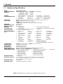
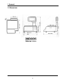

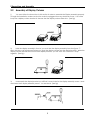
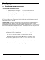
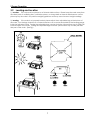

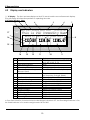
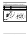


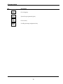
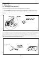

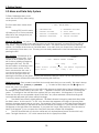
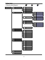
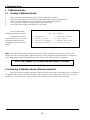
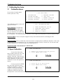
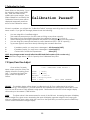
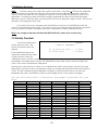
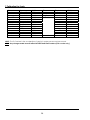
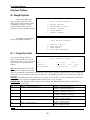
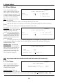
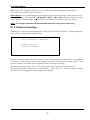
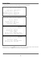

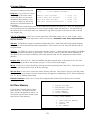
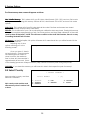
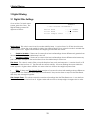
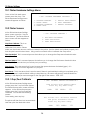

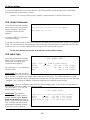

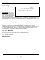
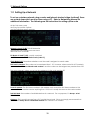


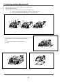
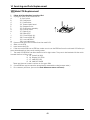
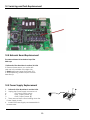
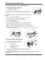

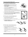
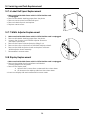
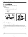
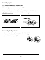
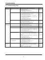

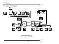
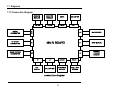

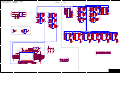
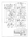
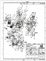

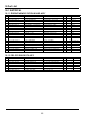
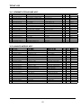
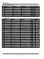

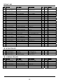
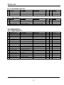


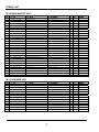
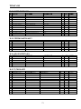


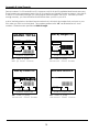
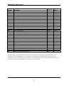


![ZXmore-V11-ConstructionKit [1144.78] KB](http://vs1.manualzilla.com/store/data/005859049_1-e30fafda14586d16f36a324828eeb8d9-150x150.png)