1
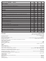
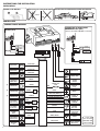
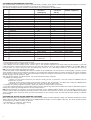
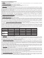
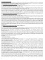
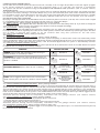
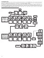
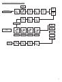
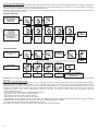
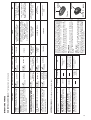
H.P.A.
High Performance Alarm
INSTALLER’S MANUAL
Release 02
Dear Installer,
Congratulations on your choice of a MetaSystem product! We would like to ask you to read the instructions
in this manual carefully as you will find it contains useful information to get acquainted with the many possibilities that the
H.P.A (High Performance Alarm) range of products is able to offer.
After you have installed the product according to the “installation instructions” supplied with the product, and which
you will also find below, the alarm control unit must be programmed in order to customise the product based on the vehicle
that it is installed on.
When you have finished the job, it is important to remember to give the user’s handbook to the owner of the vehicle
and to show him the various features of his car alarm system. Please remember to fill out the “certificate of installation” in
the user’s handbook (European Directive) and to give the owner the red card that he will need should he decide to order any
extra remote controls, as well as the OVERRIDE CARD where you should have already written the owner’s emergency code,
customised according to his choice.
Best Regards !
INDEX
- Introduction
3
- The Range of H.P.A. products
4
- Technical specifications
5
- Instructions for installation
6
- Customising the operating functions
8
- Checking the setting of the operating functions
8
- Description of the operating functions
9
- The override code
12
- Remote controls
15
- Emergency keys
15
- Checking the remote controls and emergency keys
15
- The garage function
16
- The control unit’s power supply
16
- Memory of triggered alarms
16
- Final Check
16
- Instructions for use
17
2
THE H.P.A. RANGE
Rel.02
ARMING / DISARMING
2-button remote control with programmable function buttons – random rolling code
Passive arming of alarm – selection according to preference
Passive arming of immobiliser– selection according to preference
‘Distraction-proof’ re-arming - selection according to preference
Emergency override code – customised according to preference
Electronic emergency key - random rolling code
Key 4 keypad
IMMOBILISER
Relay for engine immobilisation (10A)
ALARM: protection and signals
Protection of doors/bonnet/boot – negative input – 3 wires
Auxiliary protection – positive input – can be excluded by remote control
Digital ultrasonics with programmable adjustment of sensitivity – can be excluded by remote control
Current drop sensor –selection according to preference
Ignition sensing
Panic alarm - selection according to preference
Anti carjacking with triggering of alarm and immobilisation of ignition (3 modes can be selected)
HPA
2,5
HPA
3,0
HPA
3,5
HPA
4,0
OPT
OPT
OPT
OPT
OPT
OPT
OPT
OPT
Safety lock - automatic locking of doors when travelling (input for mileometer or brake pedal) - selection according to preference
Buzzer - selection according to preference
Blinker
M02 siren without battery back up
SC1 coded siren with battery back up
Output for control of continuous/alternating siren/horn - selection according to preference
SERVICES
LED with memory of triggered alarms
Switch/LED for override code
Universal central door locking – 6 wires – with selection of timing
Control of original comfort closing of electric windows or via remote control - selection according to preference
Control of safety dead lock on central locking - selection according to preference
Control of automatic electric windows module (M8) or via remote control (M2008) - selection according to preference
Exclusion of ultrasonics and auxiliary protection by remote control
Garage function – exclusion of passive arming
Signals if car battery is flat
Signals open doors/ tests alarm inputs
TECHNICAL SPECIFICATIONS
Power Supply.........................................................................................................................................................12Vdc (10V-15V)
Consumption..........................................................................................................................(alarm armed with ultrasonics) 10 mA
...........................................................................................................................................(alarm armed without ultrasonics) 8 mA
...................................................................................................................................................................(alarm disarmed) 6 mA
Operating temperature.................................................................................................................................................-25°C+ 85°C
Sound level of siren............................................................................................................................................................118 dB
Autonomy of back-up battery (SC1)..................................................................................................................................5 minutes.
Remote controls (max.7)..........................................................................................72 million billion rolling codes (lithium batteries)
Emergency keys (max 4)......................................................................................................................18 billion billion rolling codes
Emergency “override” code to reset immobiliser and inhibit alarm functions.
RELAY CONTACT CAPACITY
Central door locking.................................................................................................................................................................10A
Engine immobiliser relay...........................................................................................................................................................10A
Direction indicators relay.......................................................................................................................................................5A+5A
Horn control.................................................................................................................................................Negative electronic 1A
TIMING
Initial immunity time......................................................................................................................................................26 seconds
Duration of alarm cycle..................................................................................................................................................26 seconds
Interval between alarm cycles..........................................................................................................................................5 seconds
Delay for passive arming of engine immobiliser.....................................................................................(with engine off) 240 seconds
.........................................................................................................................................(with door open - engine off) 50 seconds
Delay for passive arming with alarm functions................................................................................................................ 30 seconds
Intermittence of direction indicators when alarm triggered..................................................................................................0.4 sec.on
....................................................................................................................................................................................0.4 sec.off
Timing options for opening – closing doors.....................................................................................0.5 sec.-1.5 sec.-4.5 sec.-15 sec.
Timing for comfort closing..............................................................................................................................................0.5-15 sec.
N° of permitted times for starting vehicle in garage mode.............................................................................................................15
‘Distraction-proof’ re-arming........................................................................................................................................120 seconds
ALARM CYCLES
Peripheral alarm inputs (doors, bonnet, boot).....................................................................................................................10 cycles
Ignition sensing...............................................................................................................................................................10 cycles
Ultrasonics......................................................................................................................................................................10 cycles
Auxiliary modules.............................................................................................................................................................10 cycles
Current drop sensor..........................................................................................................................................................10 cycles
3
INSTRUCTIONS FOR INSTALLATION
INSTALLATION
CONNECT CAR BATTERY
INSTALLATION OF SIREN UNDER BONNET
-
+
INSTALLATION OF ULTRASONIC VOLUME PROTECTION
B
B
B
A
80°C
A
A
H2O
CONNECTIONS
GENERAL WIRING DIAGRAM
CONNECTION OF ELECTRONIC
EMERGENCY KEY (OPT)
CONNECTION OF KEY 4
KEYPAD (OPT)
GREY
(cannot be used if KEY 4 KEYPAD is connected)
ANTENNA
LEAVE LOOSE
(DO NOT TIE DOWN)
GREY
RED
Key 4
BATTERY
POSITIVE
(+30)
ANTENNA
LEAVE LOOSE
(DO NOT TIE DOWN)
RECEPTACLE FOR
EMERGENCY KEY
(OPT)
KEYPAD
Key 4
SWITCH/LED
DIRECTION
INDICATORS
LIGHT BLUE
DIRECTION
INDICATORS
LIGHT BLUE
SWITCH/LED
DARK BLUE
IMMOBILISER
WHITE
NEGATIVE
CONTROL OF
HORN RELAY
BROWN
*
DOOR
PROTECTON
GREEN
*
BONNET
PROTECTION
*
BOOT
PROTECTION
PURPLE
PURPLE
BLACK
M02 SIREN
(H.P.A. 2.5-3.5)
SC1 SIREN
(H.P.A. 4.0)
POSITIVE
ALARM
INPUT
ANTI
CARJACKING
SWITCH (OPT)
BATTERY
POSITIVE
(+30)
4
SEE
FIG.3
BLACK
RED
RED/BLUE
BLACK
YELLOW
BLACK
SEE
FIG.5
SEE
FIG.6
RED
RX
ULTRASONIC
VOLUME
SENSOR (RED)
TX
ULTRASONIC
VOLUME
SENSOR
MOUNT 15A
FUSE
BATTERY
POSITVE
(+30)
BLACK
EARTH
LIGHT BLUE/WHITE (C)
LIGHT BLUE/YELLOW (NO)
LIGHT BLUE/BLACK (NC)
CONTROL OF
CLOSING
RED/WHITE (C)
RED/YELLOW (NO)
RED/BLACK (NC)
CONTROL OF
OPENING
POSITIVE
IGNITION
KEY (+15)
ORANGE
PINK
GREEN/BLACK
AUX
POSITIVE CONTROL
OF AUXILIARY
MODULES
MILEOMETER
SIGNAL
RED
PINK/BLACK
CONTROL OF
ELECTRIC WINDOWS
(M2008 OPT)
* = O NLY USE
THE EXISTING
SWITCHES IF THEY
CLOSE TO EARTH
PERIPHERAL PROTECTION – BONNET *
PERIPHERAL PROTECTION – DOORS *
12
PERIPHERAL PROTECTION – BOOT *
24
+ 30
MOUNT A
SWITCH
FOR BONNET
PROTECTION
GREEN
INTERNAL
BOOT
LIGHT
PURPLE
M134
DIODE
MODULE
OR (X4)
1N4002
DIODES
1
13
ORIGINAL
BOOT
SWITCH
INSERT IN
PIN. 13
ORIGINAL
DOOR
SWITCHES
+
PURPLE
SIREN FOR H.P.A. 4.0
SIREN FOR H.P.A. 2.5 -3.5
24
12
M02
SC1
24
12
CONNECTOR
OF CABLE
FOR H.P.A.
CONTROL UNIT
CONNECTOR
OF CABLE
FOR H.P.A.
CONTROL UNIT
INSERT IN
PIN.2
INSERT
IN PIN.2
M02
1
13
RED
INSERT
IN PIN.14
BLACK
SC1
WIRING DIAGRAM FOR NEGATIVE CENTRAL LOCKING
CLOSES
RED/DARK BLUE
WIRING DIAGRAM FOR POSITIVE CENTRAL LOCKING
LIGHT BLUE/WHITE
RED/WHITE
RED/YELLOW
LIGHT BLUE/YELLOW
OPENS
INSERT IN
PIN.1
BLACK
BLACK
INSERT IN
PIN.14
13
1
+30
LIGHT BLUE/WHITE
RED/WHITE
RED/YELLOW
LIGHT BLUE/YELLOW
FUSIBILE
ORIGINAL
CENTRAL
LOCKING
CONTROL UNIT
OPENS
CLOSES
ORIGINAL MOTOR ON
DRIVER’S DOOR
WITH INCORPORATED SWITCH
ORIGINAL
CENTRAL
LOCKING
CONTROL UNIT
+30
ORIGINAL MOTOR ON DRIVER’S DOOR
WITH INCORPORATED SWITCH
IMMOBILISATION
+50
WHITE
DARK BLUE
+15
ELECTRONIC
INJECTION OF
PETROL PUMP
87
+30
30
+30
STARTER
MOTOR
MOUNT
ADDITIONAL
30A RELAY
86
85
WHITE
BLUE
HORN WITH POSITIVE CONTROL– SUBKEY
HORN WITH NEGATIVE CONTROL– SUBKEY
+30 OR +15
+30
+30 OR +15
+30
HORN
ORIGINAL
HORN
CONTROL
MOUNT AN
ADDITIONAL
RELAY
87
+30
87
30
87
30
86
85
MOUNT AN
ADDITIONAL
RELAY IF HORN
SUBKEY
30
ORIGINAL
HORN
RELAY
+
86
86
85
85
BROWN
HORN
BROWN
ORIGINAL
HORN
CONTROL
5
CUSTOMISING THE OPERATING FUNCTIONS
The installed alarm system has a series of preset factory settings, which can be modified according according to the vehicle
that the alarm system is to be installed on as well as the owner’s preferences.
The factory settings and their possible customisations are illustrated in the table below.
N°
TYPE OF FUNCTION
1
2
3
4
5
6
7
8
9
10
11
12
13
14
15
16
17
18
19
20
21
22
23
24
25
buzzer
control of horn/siren
safety lock
sensibility of volume protection
current drop sensor
short timing for central door locking
long timing for central door locking
comfort closing
automatic comfort
dead lock
control of electric windows
panic alarm
test of peripheral alarms
intentional anti carjacking function
automatic anti carjacking function 1
automatic anti carjacking function 2
not used
siren supplied
Key 4 keypad
control of safety locking
distraction-proof rearming
function of remote control buttonss
passive arming with alarm functions
passive arming of immobiliser
peripheral alarms active
BUTTON A
selection A
(flashing led)
yes
continuous
yes
standard
yes
0,5 sec
1,5 sec
yes-manual
yes
yes
automatic
yes
yes
yes
yes
yes
-SC1
yes
brake pedal
yes
factory setting
yes
yes
derived
1 alarm only
BUTTON B
selection B
(led off)
no
alternating
no
reduced
no
function 7
4,5 sec
no
no
no
manual
no
no
no
no
no
-M02
no
mileometer
no
custom setting
no
no
continuous
FACTORY SETTING
standard configuration
no
alternating
no
standard
no
0,5 sec
1,5 sec
no
no
no
manual
no
yes
no
no
no
-according to kit
no
mileometer
no
factory setting
no
no
derived
Proceed as follows to modify the factory setting:
- arm the alarm system with the remote control;
- turn the ignition key to its ON position in order to switch the vehicle’s dashboard on;
- press button A on the remote control 4 times (fig. 1): the direction indicators will flash each time the button is pressed;
- after the button is pressed for the fourth time, the siren will make a series of signals (M02=4 BOOPS - SC1=4 BIP- BIPS) to
confirm that you have accessed the programming mode for the operating functions: the LED flashes quickly
N.B. you can only modify one function at a time.
- Press the button on the SWITCH/LED module installed on the dashboard or press button 1 on the keypad, if present, for the
same number of times as the function you want to set (the direction indicators flash to confirm each time you press the button
and go from one function to the next): if the LED flashes slowly the setting of the function is the “A selection” type, if it remains
off the setting is the “B selection” type;
The Led flashes quickly to indicate that a ‘not used’ function has been selected
- to change the setting, press
• button A on the remote control if you want the setting as per “A selection”: the siren makes one BEEP sound to
confirm this, or press
• button B on the remote control if you want the setting as per “B selection”: the M02 siren makes one BOOP sound
to confirm this; if you have installed a SC1 siren, this will make 2 BIP sounds;
- to change the setting of another function, repeat the 2 previous steps within 20 seconds;
- to exit the operating functions customisation phase, turn the ignition key back off and switch the vehicle’s dashboard off, then
disarm the system by pressing button A on the remote control.
N.B. During selection of a function, if you press the button on the SWITCH/LED or button 1 on the keypad, if present, for a
number of times that corresponds to a function which is not used or one that does not exist, you will hear 4 BOOPS of the M02
siren or 8 BIPS of the SC1 siren when you press the button on the remote control, and the LED will flash quickly to indicate
the anomaly.
CHECKING THE SETTING OF THE OPERATING FUNCTIONS
When customising the operating functions, you can check the status of each individual setting. The LED will indicate the current
setting after you have pressed the button on the SWITCH/LED or button 1 on the keypad, if present, the same number of times
as the function you want to check, as follows:
- slow flashing = “A selection” type setting
- off = “B selection” type setting
6
DESCRIPTION OF THE OPERATING FUNCTIONS
1 - BUZZER - Factory Setting: disabled
The acoustic signal provided by the siren when the alarm system is armed and disarmed. Its use is not permitted in countries
in the European Community.
2 - CONTROL OF HORN/SIREN - Factory Setting: alternating
Negative signal (1A max) to control the horn or additional siren during an alarm cycle.
Select alternating to control a horn, continuous to control a siren.
3 - SAFETY LOCK - Factory Setting: disabled
This function guarantees that the doors will always be locked via the central door locking system when the vehicle is in motion,
and thus prevents any attempt to open the doors from the outside. The doors are locked automatically with the timing selected
for UNLOCK TIMING. The LOCKING control is performed according to the selection made for function 20 and the relative connection
of the green/black wire. In fact it is possible to select the door locking control whilst the vehicle is in motion if it comes from
the mileometer wire or the brake pedal.
MILEOMETER (connect the green/black wire from the alarm control unit to the vehicle’s mileometer signal). The locking control
is performed after the ignition is switched on, the doors are locked and the vehicle has been in motion for at least 10 seconds.
BRAKE PEDAL (connect the green/black wire from the alarm control unit to the vehicle’s brake pedal). The locking control is
performed the second time the brake pedal is pressed if the doors are locked and the instrument panel is on (+15 ON) The
INTENTIONAL ANTI-CARJACKING and ANTICARJACKING 1 functions are not possible with this selection.
The doors will only be unlocked if a door is opened from the vehicle interior or if the engine is turned off.
4 - SENSITIVITY OF VOLUME PROTECTION - Factory Setting: standard
The particular technology used for the ultrasonic volume protection results in only real attempts to break into the vehicle interior
being detected and false alarms being ignored. We recommend the use of reduced sensitivity for vehicles with a small interior
(for example double volume vehicles).
5 - CURRENT DROP SENSOR - Factory Setting: disabled
As the alarm is being armed, the control unit memorises the consumption of the vehicle’s electrical system and triggers an alarm
if there is any variation in this. WARNING: the current drop sensor cannot replace peripheral protection because the current drop
sensor will remain inactive if the bulb in the vehicle’s interior light does not come on when a door is opened.
N.B. To ensure correct operation of the current drop sensor, do not connect the alarm’s positive supply directly to the battery,
but to a derived line (e.g. fuse box). If operation of the current drop sensor has been selected, the 4 direction indicators can
still be used in case of emergency without triggering an alarm even if the alarm is armed.
6_7_8_9 - TIMING FOR CENTRAL DOOR LOCKING - Factor y Setting: 0.5 seconds, comfor t disabled
It is possible to select the timing for locking and unlocking of the central door locking system from between 0.5 sec, 1.5 sec
and 4.5 seconds.
In addition, if the comfort function is selected, the locking time depends on how long the button on the remote control is kept
pressed, for up to maximum of 15 seconds. If the button is released before the 15 seconds are over, the control of the locking
will be interrupted. If the automatic comfort function is selected, the locking time will be fixed at 15 seconds. When the comfort
function is operational, the duration of the unlocking control can be 0.5 sec, 1.5 sec and 4.5 seconds.
The possibilities for selection are shown in the table below
LOCKING TIME
UNLOCKING TIME SETTING OF FUNCTIONS 6 - 7 - 8 - 9
short = 0,5 sec. short = 0,5 sec. 6 = selection A 7 = selection A 8 = selection B 9 = selection B
medium = 1,5 sec. medium = 1,5 sec. 6 = selection B 7 = selection A
8 = selection B 9 = selection B
long = 4,5 sec.
6 = selection B 7 = selection B 8 = selection B 9 = selection B
long = 4,5 sec.
manual
short = 0,5 sec. 6 = selection A 7 = selection A 8 = selection A 9 = selection A
comfort
medium = 1,5 sec. 6 = selection B 7 = selection A 8 = selection A 9 = selection A
0,5÷15 sec.
6 = selection B 7 = selection B 8 = selection A 9 = selection A
long = 4,5 sec.
automatic
short = 0,5 sec. 6 = selection A 7 = selection A 8 = selection A 9 = selection A
comfort
medium = 1,5 sec. 6 = selection B 7 = selection A 8 = selection A 9 = selection A
0,5÷15 sec.
long = 4,5 sec.
6 = selection B 7 = selection B 8 = selection A 9 = selection A
10 – DEAD LOCK - Factory Setting: disabled
This function allows you to control an additional feature of the central door locking system using your remote control as it controls
the safety locking of the vehicles with this system (Opels, recent Fiats etc) when both locking and unlocking the doors. The
locking and unlocking controls are activated for the time set as per functions 6_7_8_9 and then are reactivated for a further
0.5 sec after a pause of 0.5 sec. for locking and 1 sec for unlocking.
The Dead Lock controls are not produced during the activation of the Safety Lock function (if enabled).
11 - CONTROL OF ELECTRIC WINDOWS - Factory Setting: manual
This control makes it possible to control the closing of the vehicle’s electric windows by means of the M2008 module (optional)
or to control the vehicle’s original control box. Manual mode can be selected for the M2008 module, which enables the windows
to be closed for as long as the button on the remote control is being pressed (12 sec max). If the button is released before
the 12 sec timing is over, the closing of the windows will stop. Automatic mode is to close the windows with 12 sec timing with
one press of the button on the remote control.
It is possible to prevent the closure of the electric windows for one cycle of arming/disarming of the alarm system; this is useful
in summer if you want to leave the vehicle parked with its windows slightly opened or if you have to leave a pet in the car. Press
the button on the SWITCH /LED or button 1 on the keypad, if present, before arming the alarm system with the remote control.
The alarm system must then be armed within 60 sec of pressing the SWITCH /LED
12 - PANIC ALARM - Factory Setting: disabled
This function allows you to trigger a max 10 sec alarm cycle with the remote control; it can also be interrupted by remote control.
Its operation depends on the setting of FUNCTION OF REMOTE CONTROL BUTTONS (function 22):
FACTORY SETTING: when the control unit is not armed, trigger this function by pressing button B on the remote control; the same
button can be used within 10 seconds to interrupt it. If the control unit is armed, the function can be triggered after the initial
immunity time by pressing button B. Press it again within 10 sec, to stop the panic alarm.
CUSTOM SETTING: when the control unit is armed, the function can be triggered after the initial immunity time by pressing button
A. Press it again within 10 sec to stop the panic alarm. It is not possible to trigger a panic alarm if the control unit is not armed.
13 - TEST OF PERIPHERAL ALARMS - Factory Setting: activated
If the vehicle has an internal light with delayed switch off, or with particular connections, the alarm control unit could interpret
this as an open door when it is armed, resulting in 1 BOOP signal for the M02 siren or 2 BIPS for the SC1 siren.
If this is the case, we recommend neutralizing this function to eliminate the inaccurate signal.
7
ANTI CARJACKING FUNCTION
Only one anti carjacking method mode can be enabled at a time: when one method is enabled the other two are automatically
neutralised. If the brake pedal has been enabled in the Safety Lock function (see Function 3), the activation of INTENTIONAL
ANTI CARJACKING mode and AUTOMATIC ANTICARJACKING 2 is also neutralised.
14 - INTENTIONAL ANTI CARJACKING FUNCTION - Factory Setting: disabled
Conditions a, b and c must be met if this function is required.
a) The dedicated anti-carjacking switch must be installed (see wiring diagram for details on connection); this must be located
in a place that is not visible but is within easy reach of the driver.
b) To ensure correct operation of this function (European Directive), it is absolutely essential to interrupt the operation of the
vehicle’s starter motor with the dark blue and white wires from the alarm control unit.
c) It is also necessary to connect the green/black wire from the alarm control unit to the mileometer signal from the vehicle.
In case of danger, this function enables the activation of a timed procedure that triggers an alarm cycle and prevents the engine
being started. After the anti-carjacking switch has been pressed (the LED will flash once), the ignition will be immobilised if the
vehicle has been in motion for at least 1 minute and then has stopped (speed 0) for at least 5 seconds.
A 25 second alarm cycle indicates that the ignition immobilisation protection has been activated. If the engine is now turned
off, it is only possible to turn it back on 3 times, and then the vehicle will be totally immobilised. The remote controls are
neutralised after this function has been armed and it is only possible to exit it by means of the OVERRIDE code.
15 - AUTOMATIC ANTI CARJACKING FUNCTION 1 - Factory Setting: disabled
Conditions a and b must be met if this function is required.
a) The dedicated anti-carjacking switch must be installed (see wiring diagram for details on connection); this must be located
in a place that is not visible but is within easy reach of the driver.
b) To ensure correct operation of this function (European Directive), it is absolutely essential to interrupt the operation of the
vehicle’s starter motor with the dark blue and white wires from the alarm control unit.
This function protects the vehicle in case of unauthorised use by triggering an alarm cycle and preventing the engine from being
started. Every time a door is opened and the vehicle starts up, the direction indicators will flash for a set time unless the anti
carjacking switch is pressed, followed by the immobilisation of the ignition and the sounding of the siren. The anti carjacking
switch must be pressed after the door has been opened and the ignition is started, keeping it pressed until the LED flashes
once. If it is not pressed within max 20 seconds of the ignition being started, there will be a continual series of BEEPS by the
siren and flashing of the direction indicators for 30 seconds, followed by the flashing of the direction indicators alone for another
90 seconds, to remind the driver to press the appropriate switch. If he still does not press the switch, an alarm cycle will be
triggered and the ignition will be immobilised. If the engine is now turned off, it is only possible to turn it back on 3 times, and
then the vehicle will be totally immobilised. It is only possible to exit this function after it has been armed by means of the
OVERRIDE code.
16 - AUTOMATIC ANTI CARJACKING FUNCTION 2 - Factory Setting: disabled
Conditions a, b, c, d and e must be met if this function is required.
a) The optional KEY 4 keypad must be installed
b) To ensure correct operation of this function (European Directive), it is absolutely essential to interrupt the operation of the
vehicle’s starter motor with the dark blue and white wires from the alarm control unit.
c) It is also necessary to connect the green/black wire from the alarm control unit to the mileometer signal from the vehicle.
d) Function 19 must be enabled by selecting A during the ‘Customising The Operating Functions’ stage
e) Store the velocity signal for the vehicle not in motion and the maximum speed allowed. (refer to the ‘Memorising the mileometer
frequency’ section)
This function protects the vehicle in case of unauthorised use by triggering alarm cycles and preventing the engine from being
started. Every time a door is opened and the vehicle starts up, the Led will light up and the buzzer will sound on the keypad,
the direction indicators will flash, the siren or horn output will be activated for a set time, followed by the immobilisation of the
ignition unless the 4-digit password is keyed in using the keypad. Once the vehicle is in motion, the remote controls will be
neutralised until the correct code is keyed in using the keypad.
ACTIVATION
The following events must occur, in any order:
- closure of last open door
- instrument panel switched on (+15 ON)
- vehicle immobile (not in motion) for at least 2 sec.
If the correct password is keyed in when the instrument panel is on (+15 ON), this function is neutralised.
If the wrong password is keyed in when the instrument panel is on (+15 ON), the system goes onto the next stage.
START OF INTERNAL SIGNALLING
If the correct password is not keyed in within 180 sec. from when the vehicle starts moving, the LED and the BUZZER on the
KEY 4 keypad are activated intermittently. If the wrong password is keyed in during this 180 sec period, the LED and the BUZZER
immediately become active. If the engine is turned off (+15 OFF) during this 180 sec period, the countdown is immediately
interrupted until the instrument panel is turned on again (+15 ON). After the 180 sec period, the LED and the BUZZER are
activated intermittently for 60 sec
If the correct password is keyed in when the instrument panel is on (+15 ON), this function is neutralised.
If the wrong password is keyed in when the instrument panel is on (+15 ON), the system goes onto the next stage.
START OF EXTERNAL SIGNALLING
45 sec after the start of internal signalling (the LED and BUZZER) without the correct password being keyed in, the siren, horn
output and the direction indicators are activated. (180+45 sec from the moment when the vehicle started moving).
If the correct password is keyed in when the instrument panel is on (+15 ON), this function is neutralised.
If the wrong password is keyed in when the instrument panel is on (+15 ON), the system goes onto the next stage.
START OF IGNITION IMMOBILISATION
15 sec after the activation of the external signalling (siren, horn, direction indicators) without the correct password being keyed
in, the ignition immobilisation relay will be intermittently and progressively piloted for 3 minutes and the alarm cycles will continue.
This operating mode will also result in the gradual slowing down of the vehicle’s speed, in the countries where this is allowed,
if the above relay intervenes either on the fuel pump or the +15.
The gradual reduction in speed will continue until the maximum limit is reached (see function 20). Once this speed has been
reached, no further action will take place on the engine immobilisation if it is not exceeded. If the instrument panel is turned
off (+15 OFF), the external signalling will stop and the engine can be turned on again within 60 sec (it is possible to accelerate
until the maximum speed limit is reached, then the engine immobilisation relay will inter vene intermittently).
If the correct password is keyed in when the instrument panel is on (+15 ON), this function is neutralised.
If the wrong password is keyed in when the instrument panel is on (+15 ON), the system goes onto the next stage.
8
COMPLETE ENGINE IMMOBILISATION
60 sec after the instrument panel has been turned off (+15 OFF), it will no longer be possible to start the engine up again.
If the correct password is keyed in when the instrument panel is on (+15 ON), this function is neutralised.
The system can also be neutralised using the RESTORING THE OVERRIDE CODE procedure (refer to relative section).
TEMPORARY BLOCK
If 3 wrong codes are keyed in consecutively, the system enters a temporary blocked mode and does not accept any further
attempts for 10 minutes, making 3 consecutive Beeps every 5 sec (the instrument panel must remain switched off +15 OFF).
It is possible to key the correct password in only at the end of this timed stage with the instrument panel turned on (+15 ON).
If a further 3 wrong codes are keyed in, the temporary blacked mode will last for 20 minutes, then 30 minutes...
NEUTRALISING THE ANTI CARJACKING
By keying in a 4-digit password on the KEY PAD 4 when the instrument panel is turned on (+15 ON). If the correct code is keyed
in, a long BEEP will be heard, whereas the wrong code will result in 3 consecutive Beeps.
18 - SIREN SUPPLIED - Factory Setting: according to the type of siren supplied
The alarm system can be supplied with either the M02 siren or the SC1 siren with battery back up. If you want to change the
siren supplied with the other version, the setting of this function must be changed accordingly.
19 - KEY 4 KEYPAD - Factory Setting: disabled
The keypad replaces the LED/SWITCH and electronic emergency keys set (which can not operate together with the keypad). It
is complete with a LED for signalling the status of the alarm system, a buzzer and 4 backlit keys (these light up the first time
one of them is pressed and remain lit for 15 seconds after they were pressed for the last time).
20 - SAFETY LOCK CONTROL - Factory Setting: mileometer
See function 3
21 - DISTRACTION-PROOF REARMING FUNCTION - Factory Setting: disabled
This function enables the control unit to rearm the alarm system completely 2 minutes after it was last disarmed by remote
control, provided the status of the doors, boot and bonnet remains unchanged during this time. If the volumetric protection was
excluded when the system was previously armed, it will be excluded again when the system is automatically rearmed.
22 - FUNCTION OF REMOTE CONTROL BUTTONS
The way the buttons on the alarm system’s remote control operate can be customised as shown in the table below: the system
is supplied with the complete set of factory settings.
FUNCTION
ARMING: with manual and automatic comfort closing of
electric windows, if selected by installer
DISARMING: the system will rearm completely unless you
enter the interior within 2 minutes and the distraction-proof
function is enabled
EXCLUSION OF ULTRASONIC VOLUME PROTECTION AND
AUXILIARY MODULES: press within 25 sec. of arming
FACTORY SETTING
CUSTOM SETTING
BUTTON A
BUTTON A
BUTTON A
BUTTON B
BUTTON B
1st press US
2nd press auxiliary
modules
BUTTON A
1st press US
2nd press auxiliary
modules
STOP ALARM CYCLE: without disarming the system
BUTTON B
PANIC: can be triggered when control unit is armed, after
initial immunity time, max 10 sec. duration, can be stopped
BUTTON B
Can also be trigged
if control unit is
disarmed
BUTTON A
BUTTON A
23 - PASSIVE ARMING WITH ALARM FUNCTIONS - Factory Setting: disabled
This allows the peripheral protection of the alarm system to be armed automatically 30 seconds after the last open door is
opened and the instrument panel is switched off (+15 OFF). The direction indicators flash 2 times to signal the system is armed
and the LED flashes very quickly during the initial immunity time to indicate that the volume protection is not operational.
After the initial immunity time, any alarm stimulus will trigger a PRE-ALARM signal lasting 5 seconds during which the siren will
make a series of BEEP sounds: if the system is not disarmed before this time is over, a full alarm cycle will be triggered at the
end of the pre-alarm signal. The alarm can be disarmed by means of the remote control.
Automatic passive arming can be temporarily neutralized with the garage function (see relative section)
24 - PASSIVE ARMING OF IMMOBILISER - Factory Setting: disabled
This allows the immobiliser to be armed automatically by the control unit:
- 4 minutes after the engine has been turned off, or
- 50 seconds after a door has been opened if the engine has been turned off
Automatic passive arming can be temporarily neutralized with the garage function (see relative section)
25 - PERIPHERAL ALARMS ACTIVE - Factory Setting: derived (1 alarm only)
It is possible to choose if an ongoing alarm trigger is to correspond to a single alarm cycle, or to consecutive alarm cycles up
to a maximum of 10 (European Directive)
9
THE OVERRIDE CODE
In emergency situations, the alarm system can be neutralized by means of the OVERRIDE code. This is keyed in by using the
button on the SWITCH/LED mounted on the dashboard or via the KEY4 keypad, if present. The code set during production in
the factory is the same for all control units, i.e. 1 1 1 1 1 or 1111 if the keypad is enabled.
It is absolutely essential to customise this code; ask the owner of the vehicle for a sequence of 5 digits of his choice, not
including 0, if the SWITCH/LED is mounted. If the keypad has been mounted the code has 4 digits made up of the keys 1, 2, 3
and 4 on the keypad. This code must be stored in the control unit’s memory as shown in the procedure below, and then noted
on the OVERRIDE CARD provided with the system and kept in a safe place by the owner of the vehicle.
CUSTOMISING THE OVERRIDE CODE WITH SWITCH/LED
1 Beep
WITHIN 10 SEC.
ARM DE
ALARM
WITHIN 10 SEC.
WITHIN 10 SEC.
ON
OFF
X4
KEY IN STANDARD
CODE 11111:
Press the switch
immediately after
the same
number of flashes by the
LED as the individual
digit
of the OVERRIDE code
FLASH
FLASH
FLASH
X1
X1
X1
FLASH
M02 = 4 Boop
SC1 = 8 Bip
FLASH
X1
X1
WRONG
CODE
WITHIN 1,5 SEC.
WITHIN 1,5 SEC.
WITHIN 1,5 SEC.
CORRECT
CODE
WITHIN 1,5 SEC.
WITHIN 1,5 SEC.
M02 = 2 Beep
2 Boop
SC1 = 2 Beep
4BIp
WITHIN 10 SEC.
LED ON WITHOUT
FLASHING
WITHIN 10 SEC.
ON
OFF
KEY IN CUSTOMISED
CODE EG. 13212:
Press the switch
immediately after
the same number
of flashes by the LED
as the individual digit
of the OVERRIDE code
FLASH
FLASH
FLASH
FLASH
X1
X3
X2
X1
WITHIN 1,5 SEC.
WITHIN 1,5 SEC.
WITHIN 1,5 SEC.
FLASH
X2
WITHIN 1,5 SEC.
WITHIN 1,5 SEC.
M02 = 2 Beep
2 Boop
SC1 = 2 Beep
4BIp
WITHIN 10 SEC.
CONTROL UNIT
WITHIN 10 SEC.
WITHIN 10 SEC.
ON
ON
DISARMED
OFF
10
WITHIN 10 SEC.
OFF
CUSTOMISING THE OVERRIDE CODE WITH KEYPAD
1 Beep
of siren
WITHIN 10 SEC
ARM THE ALARM
BUTTON 1 X 4
TIMES
WITHIN 10 SEC
LED FLASHING
QUICKLY
ON
OFF
X4
WITHIN 10 SEC
LED ON
KEY IN 4
DIGITS
OF CURRENT
CODE
WHITIN
10 SEC
WRONG
CODE
3 BEEPS
CORRECT
CODE
1 LONG
BEEP
WITHIN 10 SEC
ON
OFF
LED FLASHES
RAPIDLY
1 BEEP
WITHIN 10 SEC
WITHIN 10 SEC
WITHIN 10 SEC
WITHIN 10 SEC
3 BEEPS
KEY IN CUSTOMISED
CODE
EG. 1324:
2 BEEPS
1 BEEP
1 BEEP
1 BEEP
1 BEEP
4 BEEPS
LED OFF
CONTROL
UNIT
DISARMED
ON
OFF
ON
OFF
11
USE OF THE OVERRIDE CODE
This procedure is only operational after the initial immunity time or after the anti carjacking protection has become operative.
Alarm cycles will be triggered as the code is being keyed in. If the LED/SWITCH does not work, it is also possible to insert the
code by turning the vehicle’s ignition key ON and OFF instead.
When the alarm system is armed, or when the anti carjacking protection is operational, follow the procedure illustrated below
to disarm the H.P.A. control unit.
LED/SWITCH PROCEDURE
ALARM HAS BEEN ARMED
FOR AT LEAST 25 SEC. OR
ANTI CARJACKING
PROTECTION IS
OPERATIONAL
WITHIN 10 SEC
LED ON
WITHIN 10 SEC
ON
OFF
1 FLASH
3 FLASHES
2 FLASHES
1 FLASH
1 FLASH
X2
KEY IN CODE
EG. 13212:
press the switch
immediately
after the same number of
flashes by the LED as the
individual digit of
the OVVERIDE code
CONTROL
UNIT
DISARMED
WITHIN 1,5 SEC
WITHIN 1,5 SEC
WITHIN 1,5 SEC
WITHIN 10 SEC
LED ON
WITHIN 10 SEC
WITHIN 1,5 SEC
WITHIN 1,5 SEC
KEYPAD PROCEDURE
ALARM HAS BEEN
ARMED FOR AT LEAST
25 SEC.
PROTEZIONE
ANTIRAPINA
IN ESECUZIONE
ON
ON
OFF
1 BEEP
WITHIN 10 SEC
WITHIN 10 SEC
WITHIN 10 SEC
WITHIN 10 SEC
1 LONG
BEEP
KEY IN CODE
EG.1324:
1 BEEP
1 BEEP
1 BEEP
1 BEEP
CONTROL UNIT DISARMED
OR CARJACKING PROTECTION
NEUTRALISED
WARNING: if the wrong code is keyed in 3 times, the control unit will be blocked for 10 minutes to prevent attempts to acquire
the code.
RESETTING THE OVERRIDE CODE
Should the code be lost or forgotten, the 1 1 1 1 1 factory set code, or 1111 with keypad, can be restored, and the owner’s
new code stored in again. This operation is not feasible if the system is armed (it must first be disarmed) but it can be
implemented if the vehicle is blocked or if there is an anti-carjacking alarm. In automatic anti-carjacking 2 mode, it is only
possible to implement it in the final, temporary immobilisation stage. This operation does however allow you to exit the anticarjacking phase. You must have both remote controls to do this and follow the procedure below:
- disarm the control unit;
- turn the vehicle’s ignition key ON (dashboard turned on);
- press button A on one of the 2 remote controls;
- press button A on the second remote control;
- press button A on the first remote control again;
- press button A on the second remote control again. The M02 siren will now confirm that the code has been reset by sounding
2 BEEPS followed by 2 BOOPS. The SC1 siren will make 2 BEEPS followed by 4 BIPS.
- turn the vehicle’s ignition key OFF (dashboard turned off);
N.B. Make sure that less than 5 seconds pass between one step and the next.
12
REMOTE CONTROLS
The alarm control unit is supplied with 2 coded remote controls but it is possible to add extra remote controls, up to a maximum
of 7 in all. To add new remote controls, they must first of all be ordered from your local MetaSystem Customer Care Centre;
you must indicate the base code, located on the red card supplied with the product, on your order. After you receive the remote
controls, they have to be linked up to the control unit by means of the dedicated link-up procedure.
If one or more remote controls are lost or stolen, they can be cancelled by means of this same link-up procedure, and even reset
for use should they be found again.
LINKING UP REMOTE CONTROLS
a) arm and disarm the control unit with the remote control for a total of 16 times in all. The M02 siren will now make 2 BEEPS
followed by 2 BOOPS. The SC1 siren will make 2 BEEPS followed by 4 BEEPS;
b) turn the ignition key ON within 10 secs (vehicle’s dashboard is turned on);
c) press button A on the new remote control: the LED turns on;
d) press button A on the same remote control again: the LED turns off and the siren makes a BEEP to confirm it has been
successfully linked up;
e) press button A on the second new remote control: the LED turns on;
f) press button A on the same remote control again: the LED turns off and the siren makes a BEEP to confirm it has been
successfully linked up;
g) repeat steps e and f for all the new remote controls;
h) turn the ignition key OFF (vehicle’s dashboard is turned off): the M02 siren will make 2 BEEPS and 2 BOOPS to signal the
remote controls have been stored in the control unit’s memor y; the SC1 siren will make 4 BIPS.
EMERGENCY KEYS
The alarm system can be equipped with up to 4 electronic keys for emergency disarming.
The EMERGENCY KEYS KIT (P64760) includes the receptacle, to be installed as shown in fig. 1/A, and 2 keys, which must be
stored in the control unit’s memory as described in the procedure for memorising emergency keys. It is also possible to neutralize
any lost or stolen keys by means of the same procedure, as the memorising of emergency keys automatically deletes any
previously stored keys.
MEMORISING EMERGENCY KEYS
a) arm the control unit with the remote control;
b within 10 seconds of this, turn the vehicle’s ignition key ON (dashboard is turned on);
c) within 10 seconds of this, press the button on the SWITCH/LED 4 times: the siren will BEEP once to confirm selection;
d) within 10 seconds of this, turn the vehicle’s ignition key OFF (dashboard is turned off): the LED will start to flash slowly thus
requesting the override code. The button must be pressed immediately after the equivalent number of flashes of the LED as
each individual digit in the override code;
e) The M02 siren will make 2 BEEPS followed by 2 BOOPS to confirm the correct override code; the SC1 siren will make 2 BEEPS
followed by 4 BIPS;
f) insert the emergency keys into the receptacle within 10 seconds: the LED will flash once to confirm each key has been
memorised correctly;
g) turn the vehicle’s ignition key on and off three times each to exit the procedure and finalise the storing of the emergency keys
in the control unit’s memory.
CHECKING THE QUANTITY OF REMOTE CONTROLS AND EMERGENCY KEYS
When the alarm system is disarmed, turn the vehicle’s ignition key ON (dashboard is turned on) and press button A on the remote
control: the LED will flash the same number of times as the number of remote controls that are stored in the control unit’s
memory. After a pause of 2 seconds, the flashing will start again to indicate how many emergency keys have been stored in its
memory.
MEMORISING THE MILEOMETER FREQUENCY
This enables the memorisation of the frequency of the signals found on the mileometer wire, relating to:
a) vehicle immobile with engine running (speed 0);
b) threshold for activation of intentional carjacking, maximum speed allowed by the ANTI-CARJACKING 1 function .
It is essential to enable the mileometer input for function 20. It is possible to execute it if any enabled anti-carjacking functions
are not operational (they must therefore be neutralised using the relative procedures)
Type ‘a’ memorisation alone can be done if the LED/SWITCH is mounted:
- with the control unit disarmed, turn the instrument panel on (+15 ON) and turn the engine on;
- within 10 sec of this, press the button on the LED/SWITCH 10 times: the direction indicators flash every time it is pressed,
then the siren produces a BEEP the tenth time and the LED flashes rapidly;
- within 10 sec of this, press the button on the LED/SWITCH to store the frequency at zero velocity:
the siren produces a BEEP and the LED turns off
- turn the engine and the instrument panel off (+15 OFF)
Types ‘a’ and ‘b’ memorisation can be done if the keypad is mounted:
- with the control unit disarmed, turn the instrument panel on (+15 ON) and turn the engine on;
- within 10 sec of this, press two buttons on the keypad at the same time and keep them pressed for at least 10 sec. After 10
sec have passed, the buzzer on the keypad will produce 4 short BEEPs and when the buttons are released the LED will light up
without flashing.
- within 10 sec of this, key in the 4-digit override code and make sure that less than 10 seconds pass between pressing one
button and the next. If more than 10 seconds pass, a BIP sound will signal the need to repeat the procedure from the beginning.
A long BEEP confirms the correct code has been received and the LED turns off.
- press any key on the keypad to store the speed when the vehicle is not in motion: 2 consecutive BEEPs confirm it has been
stored successfully. Turn the vehicle’s engine on and take it to the required speed (recommended 30Km/h), then press any
button on the keypad to store the speed, 2 consecutive BEEPs confirm it has been stored successfully.
- stop the vehicle and turn off the engine and instrument panel (+15 OFF) to complete the procedure.
THE GARAGE FUNCTION
The function makes its possible to temporarily neutralize the passive arming of the engine immobiliser, the passive arming with
the alarm functions, distraction-proof re-arming and anti carjacking protection.
If the anti carjacking protection has not yet been enabled, the garage function is enabled by pressing button A on the remote
control together with the button on the SWITCH/LED mounted on the dashboard: the direction indicators flash 2 times and the
siren makes 1 BEEP to confirm the function is operational. If the ignition key is turned ON (dashboard is turned on), the LED
will flash to warn that the garage function is operational.
If the anti carjacking protection has already been enabled, the garage function is enabled by pressing button A on the remote
control at the same time as the anti carjacking switch. The signals given after this are the same as those described above.
13
If the keypad has been mounted, press 2 any keys at the same time and press button A on the remote control to transmit a
signal: the keypad will produce 4 BEEPs to confirm reception. Release the 2 buttons and key in the override code within 10 sec:
the direction indicators flash 2 times and the siren produces 2 BEEPs to confirm the function has been activated.
It is possible to turn the ignition on 15 times when the garage function is operational and will remain memorised, even if the
alarm control unit‘s power supply is disconnected. To exit the garage function, arm the alarm system with the remote control.
THE CONTROL UNIT’S POWER SUPPLY
If the control unit‘s power supply is disconnected, its memory will store its previous status. When its power supply is restored,
the status of the control unit will be the same as just before the power supply was disconnected.
MEMORY OF TRIGGERED ALARMS
If various alarms have been triggered, the memory will signal them in sequence with 3 second pauses, and repeat the sequences
every 6 seconds. The memory is reset when the vehicle’s ignition is turned on or when the control unit is armed again by remote
control.
LED SIGNAL
1 FLASH
2 FLASHES
3 FLASHES
4 FLASHES
5 FLASHES
6 FLASHES
7 FLASHES
TYPE OF ALARM TRIGGERED
ULTRASONIC
DOORS
BONNET
BOOT
AUXILIARY MODULES (POSITIVE ALARM)
DASHBOARD (+15)
CURRENT DROP SENSOR
FINAL CHECK
After the alarm system has been installed and customised, it is important to check that it operates correctly by means of the
following procedure:
- connect the cable’s connector to the HPA control unit
- close the boot, sun-roof, all windows and doors
- make sure that you have not left the car keys or the remote controls inside the vehicle
- restore the connection of the car battery, then close the bonnet
- the first time it is switched on, the control unit will be disarmed
- start up the engine to check that all connections have been carried out correctly
The checks described below refer to a control unit with standard factory settings: the results of the various steps may vary
according to any customisation of the operating functions.
- arm the control unit by pressing button A on the remote control: the doors are locked by the central door locking system, the
alarm protection is operational, the direction indicators flash 2 times and the LED flashes
- during the initial 25 seconds of immunity time, complete the following tests, each of which should cause the indicators to flash
once, signalling the positive outcome of the test:
- open a door, the bonnet and the boot
- turn the ignition key ON
- insert your hand through an open window and move it backwards and forwards compared to the installed ultrasonic
capsules; the initial immunity time starts again from zero every time the indicators flash
- after the initial immunity time is over, the LED will flash more slowly and there will be a 25 second alarm cycle if you trigger
any of the alarm’s protection features: the siren produces its distinctive modulated sound, the direction indicators flash and
the horn ,if connected, sounds intermittently. Check that the immobiliser is working properly during an alarm cycle.
- disarm the alarm control unit by pressing button A on the remote control: the doors are unlocked via the central door locking
system, the direction indicators flash once, the M02 siren produces 1 BOOP sound, whilst the SC1 siren produces 2 BIPS, and
the LED flashes to indicate the memorised alarms which took place during the final check. Refer to the relative section for more
information on what these flashes stand for.
Please refer to the instructions of the individual auxiliary modules for more information on their operation, if any are installed.
14
15
BUTTON B
can also be
activated when
control unit is
disarmed
*PANIC: can be activated when control unit
is armed, after initial immunity time, max
duration 10 sec., can be interrupted by
pressing same button
FLASHING
1 FLASH
2 FLASHES
* PASSIVE ARMING OF ENGINE
IMMOBILISER: arms 4 minutes after the
engine is turned off, or 50 sec. after a door
is opened (with engine off).
* PASSIVE ARMING OF ALARM +
IMMOBILISER: arms 60 sec. after opening
and closing a door (with engine off).
PRE-ALARM: only if passive arming of alarm
has been enabled or if armed by electronic
key. An alarm cycle is produced after 5 sec.
INDICATORS
FINCTIONS
ALARM: 25 sec. cycle can be stopped by
remote control
Series of
BEEPS
for 5 sec.
SOUNDING
SIREN
BUTTON B
STOP ALARM CYCLE: without disarming the
system
ADDITIONAL SIGNALS (*configuration must be made)
BUTTON B
1st press US
2nd press
auxiliary modules
BUTTON A
BUTTON A
FACTORY SETTING
EXCLUSION OF ULTRASONIC VOLUME
PROTECTION AND AUXILIARY MODULES:
press within 25 sec. of arming.
DISARMING: if you don’t get inside the car
within 2 minutes when the distraction-proof
function has been enabled, the system will
completely rearm. The system is completely
disarmed during an alarm.
ARMING: with manual and automatic comfort
closing of electric windows if selected by
installer..
FUNCTIONS
MAIN CONTROLS AND SIGNALS (* configuration must be made)
ISTRUCTIONS FOR USE
1 FLASH
2 FLASHES
INDICATORS
Same as previous
status
Flashing very slowly
during first 25 sec.
(initial immunity time)
Flashing very
slowly
OFF
LED
BUTTON A
BUTTON A
SOUNDING
SUONDING STOPS
KEY4 Keypad:
press 2 buttons on the keypad at the same time and press
button A on the remote control to transmit a signal: the keypad
will produce 4 BEEPs to confirm reception. Release the 2
buttons and key in the override code within 10 sec: the direction
indicators flash 2 times and the siren produces 2 BEEPs to
confirm the function has been activated.
LED/SWITCH:
press button A on the remote control and the button on the
LED, the direction indicators will flash once, the M02 siren will
produce 1 BOOP sound whilst the SC1 siren will produce 2 BIP
sounds.
BUTTON B
TX mykro
M252
BUTTON A
BUTTON A
BUTTON B
Same as previous
status
FLASHING:
Flashes slowly
FLASHING: rapidly during first
25 sec. (initial immunity time)
then flashes slowly
1 BEEP (if buzzer ON*) and no alarms
were triggered. If alarms were triggered
(after the BEEP if buzzer ON* ):
M02= 1 BOOP, SC1= 2 BIPS
1 BEEP + 4 rapid BEEPS
if car battery is flat and buzzer ON*
3 BEEPS each time
button is pressed
(if buzzer ON*)
Turns off if no alarms were
triggered, otherwise
flashes to signal memorised
alarms (see relative table)
2 BEEPS (if buzzer ON*)
If peripheral protection is active:
M02= 1 BOOP, SC1= 2 BIPS
LED
FLASHING: turns off briefly
during first 25 sec. (initial
immunity time),
then flashes slowly
SIREN
GARAGE FUNCTION
Enables the passive arming of the engine immobiliser, passive
arming of alarm, distraction-proof re-arming and anti-carjacking
functions to be temporarily neutralised. If the garage function
is enabled, the engine can be turned on 15 times and remains
memorised even if the alarm control unit’s power supply is
disconnected.
When the ignition key is ON (instrument panel ON) the LED will
flash to indicate that the garage function has been selected.
Use of remote control will cancel this setting.
FLASHING
FLASHING
STOPS
BUTTON A
3 FLASHES EACH
1st press US
TIME BUTTON IS
2nd press
PRESSED
auxiliary modules
BUTTON B
BUTTON A
*CUSTOM SETTING
www.metasystem.it
MetaSystem S.p.A. • Via Oberdan
42100 Reggio Emilia • ITALY
Tel. +39-0522 364 111 • Fax +39-0522 364 150
[email protected]
Data and technical features may be changed without notice.
V808910C
C
Copyright by MetaSystem 12/2001
GRAFITALIA (RE). Printed in Italy
The best technology
for your
security