1
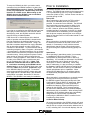
Product Manual
QD2040-ADV/MAX
Embedded Site Communication
Center
Description
Contents
The QD2040 Series Embedded Site Communication
Center is designed to act as a stand-alone web enabled
server or as a gateway working in conjunction with a
central Ubiquity server. The QD2040 offers an on-site
interface that can remotely program, schedule and
monitor the controller network through a browser. Users
can network the QD2040 utilizing an Ethernet port or
through dial-up. Loop Control and energy metering of
demand and consumption is standard to the QD2040 as
well. The QD2040-ADV (Advanced) includes standard
functionality plus support for the Superzone Commercial
Zoning System (Superzone CZS). The QD2040-MAX
(Maximum) provides standard functionality plus support
for VAV systems, the Superzone CZS, and Zigbee
Wireless.
Description . . . . . . . . . . . . . . . . . . . . . . . . . . . . . . . . . 1
Features . . . . . . . . . . . . . . . . . . . . . . . . . . . . . . . . . . 1
Material List . . . . . . . . . . . . . . . . . . . . . . . . . . . . . . . . 1
Mounting . . . . . . . . . . . . . . . . . . . . . . . . . . . . . . . . . . 3
Control Network Wiring& Setup . . . . . . . . . . . . . . . . 4
Programming . . . . . . . . . . . . . . . . . . . . . . . . . . . . . . . 5
Ubiquity Systems Software . . . . . . . . . . . . . . . . . . . . 8
Checkout and Troubleshooting . . . . . . . . . . . . . . . . . 8
LED Description . . . . . . . . . . . . . . . . . . . . . . . . . . . . 8
Features
• Integrated Web Server with 512 MB of Ram and 80 GB of
Storage Capacity
• Integrated 10/100 ethernet controller with firewall
capabilities
• Integrated Modem for dial-up or PPP (Dial-up ISP)
connections
• Embedded simple interface to program and monitor the
Controller Network
• Standard fallback alarming local to the device
• Energy Metering and Monitoring with a Modbus Veris Meter
• Interface into Ubiquity
• Integrated controller programming and scheduling
• Remotely upgradable firmware
• User definable communication cycles and packet sizes
• SSL (Secure Socket Layer) enabled web pages
• Dial-in support to interface with a controller network without
an internet connection
• Integrated controller addressing
• Multi-port network capabilities
• Energy demand limiting and, curtailment (requires controller
firmware 1.4 or later)
• Supports all TCS Basys Controllers
Material List
•
•
•
•
•
QD2040 Embedded Site Communication Center
Phone cable
Power cord
QD2040 EZ Installation & Programming Instructions
7 ft CAT 5 Crossover Patch Cable
(used for connecting directly from PC to QD2040
only)
R
2800 LAURA LANE • MIDDLETON, WI 53562 • (800) 288-9383 • FAX (608) 836-9044 • www.tcsbasys.com
1
Modes of Operation
the QD2040 Ubiquity home page. From this page
you can configure the operation mode of the QD2040
(See Setup & Programming section) by navigating to
the following links at the top of the home page Admin
> QD2040 Setup. You can now change parameters of
the QD2040 or link to the control addressing page to
address controllers, that do not have displays, prior
to installation. (See Control Addressing section) After
QD2040 configuration is complete, disconnect PC from
the QD2040. The QD2040 is now ready for installation.
There are two modes in which the QD2040 can operate.
One method is stand-alone server mode utilizing the
embedded Ubiquity software. The second method is
by directly communicating to a centrally hosted Ubiquity
server. In stand-alone mode the QD2040 functions
as the server to the controller network and can be
accessed via the Internet, through a local or wide area
network (LAN or WAN), or by dial-in modem connection.
All access methods utilize a simple web browser
interface. The QD2040 may also be accessed via direct
connection from a laptop using the included CAT 5
Crossover Patch Cable.
NOTE: Despite its appearance this is a unique cable
designed especially for direct connections between
two computers. Other ethernet cables will not work.
The other method of operation for the QD2040
is to communicate directly to a centrally hosted
Ubiquity server by connecting to the Internet or by
connecting to a local or wide area network (LAN
or WAN). By connecting to a centrally hosted server,
the advantages of multi-site enterprise functionality is
achieved. Enterprise features include: multi-site global
programming, global scheduling, global alarming and
enterprise data aggregation. In addition, some local
control functions are still performed by the QD2040 (ie.
Loop control, energy curtailment, outdoor air sharing,
etc.)
Initial Configuration
The QD2040 comes from the factory with a default
mode of Stand-alone / Dial-In. The unit also comes
with a special setup mode enabled. This setup mode
is called 'Setup DHCP Server' and in this mode the
QD2040 acts as a DHCP server which allows capability
of setting up the QD2040 by simply connecting to it
with a laptop or desktop PC. Caution: The QD2040
comes programmed with a default setup mode and
functions as a DHCP server. When setting up the
QD2040, be sure the QD2040 is not connected to
another DHCP enabled network.
Before connecting the QD2040 to a LAN or WAN, you
must first configure the unit for operation. To configure
the QD2040, connect the QD2040 to a PC or laptop that
is NOT connected to a network during the configuration
process. Make this connection from the ethernet port
of the QD2040 to the ethernet port of the PC using
the CAT 5 crossover ethernet cable included with the
QD2040. After you have made the connection from the
QD2040 to the PC, power up the QD2040 and wait 3
minutes for the QD2040 to completely boot up. You
then need to reboot your laptop or PC to allow it to be
assigned an IP address from the QD2040. Open the
web browser program (Internet Explorer v5.0 or higher
is the recommended browser). In the browser address
space, type in IP address http://192.168.1.1 and press
enter to navigate to the QD2040 login page. Enter
username: admin and password: password to reach
R
2800 LAURA LANE • MIDDLETON, WI 53562 • (800) 288-9383 • FAX (608) 836-9044 • www.tcsbasys.com
2
Prior to Installation
To setup the QD2040 via dial-in you need to make
connection from the QD2040 modem to a phone line
(See QD2040 Wiring section). Caution: The QD2040
comes programmed with a default setup mode and
functions as a DHCP server. When setting up the
QD2040, be sure the QD2040 is not connected to
another DHCP enabled network.
For Internet operation decide how the QD2040 will
connect. The QD2040 can connect to the Internet using
a TCS provided dial-up ISP or by using a broadband
connection (Cable or DSL). Internet access can also be
provided through a LAN.
Dial-up ISP
When connecting to the Internet via TCS provided
dial-up ISP, a dedicated phone line needs to be
provided for connection to the QD2040. The QD2040
has functionality to prevent excessive dialing in the
event there is difficulty establishing a connection to
the ISP. However, because the QD2040 maintains
extended periods of connectivity to the ISP, it is highly
re-commended when establishing a local calling plan
with the phone company that the plan incurs charges
based on the total number of calls made instead of total
duration of calls.
If you plan on reconfiguring the QD2040 again at a later
date, and you select Dial-Out to ISP mode or Standalone/Dial-In mode, the QD2040 can be left with the
setup DHCP Server Mode Enabled.
If Dial Out to ISP to Central Server is the desired
mode of operation and the QD2040 is located at the
final site destination, the dedicated phone line can
be used to make the dial in connection. Using a PC
with dial-out modem and phone line use the Windows
dial up networking program to make a PPP dial-in
connection to the QD2040. To reach Windows dial-up
networking navigate to Start > Programs > Accessories
> Communication > Dial-Up Networking, click on Create
a New Network and follow the prompts to complete the
connection setup. When prompted for phone number,
enter number of phone line that is plugged into the
QD2040. When prompted for 'Once a dial-in connection
is made' to the QD2040, open a web browser and
type in IP address http://192.168.2.1 (Note: This
IP address is different than the IP address that
is used when connecting to the QD2040 via the
ethernet port) to get to the QD2040 login page, enter
username: admin and password: password to login
to the QD2040 Ubiquity home page. To reach the
setup pages navigate the following menus at the top
of the page Admin > QD2040 Setup. After QD2040
configuration is complete, disconnect PC from the
QD2040. The QD2040 is now ready for installation.
Ethernet
When connecting to a centrally hosted server utilizing
the ethernet port outside of the local or wide area
network, it is necessary to verify, with the network
administrator, that the proper communication ports
are open through the corporate firewall (typically Port
80).
Stand-alone
When operating in stand-alone mode, it is necessary
to establish the URL for the QD2040. This is
accomplished by utilizing either static or DHCP IP
addressing. It is necessary to determine if the QD2040
will be accessable over a network and if so will it
utilize DHCP or static IP addressing. When using
static IP addressing, it is also necessary to establish
the Gateway, Subnet and DNS protocol setting for the
QD2040. This will need to be done by the LAN/WAN
network administrator prior to installation. When
utilizing DHCP addressing, the IP address settings
are automatically assigned when communication is
established.
When operating in communication to a centrally hosted
Ubiquity server through an Ethernet connection,
the QD2040 supports both static and Dynamic Host
Configuration Protocol (DHCP) IP addressing. When
using static IP addressing, it is also necessary to
establish the Gateway, Subnet and DNS protocol
settings for the QD2040. The IP protocol settings
will need to be established by the LAN/WAN network
administrator prior to installation. When utilizing DHCP
addressing, the IP address settings are automatically
assigned when communication is established.
Configuring the QD2040 for DHCP is outlined in the
Programming Setup section.
Controller Network Setup
All controls connected to the QD2040 network will need
to be programmed with the same communication baud
rate as well as a unique communication address from 0
to 255, excluding 248. On units with displays, this can
R
2800 LAURA LANE • MIDDLETON, WI 53562 • (800) 288-9383 • FAX (608) 836-9044 • www.tcsbasys.com
3
The QD2040 is designed to either be mounted in a
PP2000 panel, on a wall or it may be set on a table
or shelf. The PP200 panel, is custom fabricated and
designed specifically to house the QD2040 and various
other controls. When mounting to a wall, use the
QD2040 mounting bracket and select a sturdy wall made
of masonry, wood or metal. When mounting to dry
wall, it is recommended that you first attach a wood or
metal back plate to the wall and then mount the QD2040
bracket assembly to the back plate.
RS485
Modem
Power
Power cord
PI1000
Mounting
Ethernet
Phone line
USB
Serial
Ethernet Cable (Not Included)
either be done from the face of the controller using the
keypad and display or by individually direct connecting
controllers to the QD2040. On units without displays,
controller addressing is done by direct connect to
QD2040. (see Control Addressing section and Controller
Programming with the QD2040 in the Setup and
Programming Section)
POWER
QD1010
To RS485
Control Network
* If additional ports are
needed, a multi-port
USB hub can be used.
When selecting a location to mount the QD2040, be
sure to allow room for cable connections and locate the
unit in an area away from excessive dust, heat sources,
moisture, or direct sunlight. The ideal environment is
a server room. The temperature of the room can not
exceed 77ºF (25ºC), with good ventilation manditory.
QD1010
ETHERNET HUB
To RS485
Control Network
Connections
Controller Network Wiring and Setup
To power the QD2040, attach the power cord to the
QD2040 and insert the power plug into a 120 VAC
socket. Upon connection the QD2040 may power up
automatically. If it does not, simply press the power
button.
To access your controllers through Ubiquity browser
software, you will need to create an "RS485" network by
connecting all of the controllers "A" terminals together,
"B" terminals together and REF together, using 18 or 20
AWG twisted, shielded 3 conductor (triple) wire.
If a port has more than 32 Controllers or is longer than
4000 Ft., you will need a bus repeater, QD1011a. You
will need a bus repeater for each group of 32 units.
HOO PWR
Additional
USB Ports
When connecting controllers on a network, you may use
any one of a number of wiring configurations, such as
"daisy chain", "star", etc., as long as all "A" terminals
are connected to a common wire all "B" terminals are
connected to a different, yet common wire and all “Ref”
terminals conected to a third wire.
RESET
Reset Power
Button Button
The integrity of the "A", "B" and “REF” wiring runs must
be maintained or the network will not communicate
properly.
To connect the QD2040 to a LAN, connect an Ethernet
cable (not included) to the RJ-45 connection on the
back of the QD2040. Connect the other end to the LAN
network hub.
CAUTION:You must maintain proper polarity of A, B
and REF connections (see figure). All shields
must be tied together, taped off to prevent
any accidential connections then grounded
at one end of the network. Caution should
be taken to avoid running wire near power
wires, frequency drives, fluorescent lights,
ballasts, etc., which can all compromise the
communications signal. Care should also
be taken to leave as little wire exposed as
possible.
For dial-in access to the QD2040 or for dial-up ISP
function, connect phone line from modem connection on
QD2040 to phone line jack. For dial-in function it is not
necessary to have dedicated phone line. A line sharing
interface may be utilized to share line with another line
such as a fax line. A dedicated line is required for dial-up
ISP functionality.
R
2800 LAURA LANE • MIDDLETON, WI 53562 • (800) 288-9383 • FAX (608) 836-9044 • www.tcsbasys.com
4
Critical: Avoid noise on the communications line by
grounding the shield. The signal that passes information
is 1 to 5 V. If you measure across A and B, you should
get 0 VAC, and 1 to 4 VDC. There should be 0 VAC
and 0 VDC between either A on B and the shield. If
you are getting more than this, check for runs against
high voltage, for exposed wires, to see if grounding at
only one side, or that you have used dedicated power
for the controllers or if you have reversed power on a
Controller(s).
Ethernet card on the QD2040. This is important when
matching DHCP addresses with hardware on the
network (see Initial Connection section)
Communication Configuration
Before you can change the mode of operation that the
QD2040 will be operating in, you must first unckeck the
default setting of 'Setup DHCP Server' option. When
doing so you will receive a caution box to notify you that
after you finish entering setup parameters and click the
submit button, the QD2040 will reboot within 5 minutes.
There are three modes of operation that the QD2040
can operate in. They are Dial-Out to ISP to Central
Server, Ethernet to Central Server and Stand-alone /
dial-in.
Note: By using wire cable consisting of one triple
of twisted shielded wire and one pair of unshielded
wire, you can run power to controllers and run
communications wire in the same cable.
Typical cable is: PM2000.
Note: Be sure to check any local codes to confirm the
wire choice meets the code.
The QD2040 comes packaged with one QD1010
RS232/RS485 communications converter that can be
attached directly to the serial port on the QD2040. The
controller network wiring connects to the QD1010 as
described above. If using more than one port on the
QD2040, additional QD1010 devices will need to be
used (one per port). When connecting to the USB
ports, a PI1000 USB/Serial Converter is required to
connect the QD1010 to the USB port of the QD2040. Up
to 64 controllers can be placed on a single port of the
QD2040. Additional USB ports may be provided by the
use of a multi-port USB hub attached to the built-in USB
port on the QD2040.
Dial-Out to ISP to Central Server
If Dial-Out to ISP to Central Server is selected, enter
the Static IP address, Gateway, Subnet and DNS
Setup & Programming
Once you have made connection and have logged into
the QD2040 you are able to configure the operation of
the unit.
To program and setup the QD2040 when it is in StandAlone / Dial-In mode click on the Admin menu and then
click the QD2040 setup tab. Once on the QD2040 setup
page you can begin selecting the proper parameters for
your application. If the QD2040 is in Dial-Out to ISP to
Central Server or Ethernet to Central Server mode there
will be no access to the menu items of the embedded
Ubiquity software. In either case, all Ubiquity Application
software and functionality is accessed by logging into
the Central Server (www.ubiquitysystems.net)
Network Commissioning Configuration
Select whether the QD2040 will operate using a static
IP address or DHCP addressing. When using static IP
addressing as determined by the LAN/WAN network
administrator, you must enter the IP address, Gateway
protocol setting, Subnet setting and DNS setting. When
using DHCP addressing, no further settings need to be
entered in this section.
Enter correct time, date and time zone into the
appropriate areas. Also located in this section is the
infomation regarding the MAC address of the
R
2800 LAURA LANE • MIDDLETON, WI 53562 • (800) 288-9383 • FAX (608) 836-9044 • www.tcsbasys.com
5
settings. These values can be obtained from TCS if
utilizing the TCS provided ISP. You must also enter the
ISP username, ISP password and ISP Phone Number.
These values will be given to you by TCS if utilizing the
TCS provided ISP.
In this section also enter the SMTP Server settings, POP
username and password and a return email address.
You can also select when you want the QD2040 to
communicate with the server by selecting Always On,
Never On or Specifying the times. To specify the times,
select a cycle time from the drop down menu and then
select how long you want the unit to remain online from
another drop down menu.
In this section you also enable or disable Secure
Sockets Layer (SSL) communication with the central
server. SSL provides greater security of data being
passed from the QD2040 to the centrally hosted
Ubiquity server. You can also select when you want the
QD2040 to communicate with the server by selecting
Always On, Never On or Specifying the times. To
specify the times, select a cycle time from the drop
down menu and then select how long you want the unit
to remain online from another drop down menu.
Stand-alone / Dial-In
Ethernet to Central Server
If Ethernet to Central Server mode is selected, select
whether DHCP or static IP addressing is used. If
static IP addressing is selected, you must also enter
the Gateway, Subnet and DNS protocol settings. You
will be required to confirm these settings when
submitting the page. Select whether to enable or
disable Secure Sockets Layer (SSL) communication
with the central server.
Before you can setup the QD2040 to operate in the
Stand-alone / Dial-In mode, you must first uncheck the
default setting of 'Setup DHCP Server' option. When in
Stand-alone / Dial-In mode, the QD2040 functions as a
self contained server to the controller network. Disable
or enable dial-in access to the QD2040 from the drop
down menu. If enabling dial-in function, you must also
enter the dial-in username and password along with a
password confirmation. When in Stand-alone / Dial-In
mode the QD2040 can be accessed via a remote PC
using Windows Dial-Up networking, or can be accessed
over an ethernet.
R
2800 LAURA LANE • MIDDLETON, WI 53562 • (800) 288-9383 • FAX (608) 836-9044 • www.tcsbasys.com
6
To connect to the QD2040 via dial-in you need to make
connection from the QD2040 modem to a phone line
(See QD2040 Wiring section). If Dial Out to ISP to
Central Server is the desired mode of operation and
the QD2040 is located at the final site destination, the
dedicated phone line can be used to make the dial
in connection. Using a PC with dial-out modem and
phone line use the Windows dial up networking program
to make a PPP dial-in connection to the QD2040. To
reach Windows dial-up networking navigate to Start >
Programs > Accessories > Communication > Dial-Up
Networking, click on Create a New Network and follow
the prompts to complete the connection setup. When
prompted for phone number, enter number of phone line
that is plugged into the QD2040. When prompted for
Once a dial-in connection is made to the QD2040, open
a web browser and type in IP address 192.168.2.1
OTHER PROGRAMMING OPTIONS
You must select a Network Polling Cycle Time for the
QD2040. This is the time interval that the QD2040 will
poll the entire network of controllers on all ports
(For additional information on using the embedded
Ubiquity software in the QD2040, see the Ubiquity User
Manual.)
Controller Addressing
(Note: This IP address is different than the IP
address that is used when connecting to the
QD2040 via the ethernet port) to get to the QD2040
login page enter username: admin and password:
password to login to setup pages.
(For additional information on using the embedded
Ubiquity software in the QD2040, see the Ubiquity User
Manual.)
ALARM DISTRIBUTION
You can select up to six different pager numbers to be
notified in the event of an alarm. You can enter up to six
numbers to designate a Site Code. You must then enter
in the destination phone number of up to six different
pagers. In the event of an alarm, the QD2040 will dial
out to the pager and the Site Code will appear on the
pager screen.
Prior to accessing controllers via the QD2040 network,
all controls must be programmed with the same
communication baud rate as will be used for the
QD2040. All controls must also be programmed with a
unique communication address from 0 to 255 excluding
248. All controls come with a factory default address of
zero. On units with displays, control addressing can be
done using the keypad and display, by utilizing the the
QD2040 control addressing interface page. Controllers
with no displays need to be addressed through the
QD2040. To address via the QD2040 interface you
must first follow the necessary connection procedures
to access the QD2040 (see Initial Connection section).
After initial connection is established and before the
controller network is attached to the QD2040, only one
controller can be attached at a time to the QD2040 (see
Control Network Wiring and Setup section for instruction
on connecting controllers to the serial or USB ports of
the QD2040)
PORT CONFIGURATION
The communication ports are automatically detected
once the QD2040 is powered up. Once detected each
COM port needs to be configured to ensure proper
functioning of the network on each port. Each port can
be enabled or disabled from the drop down menu. You
must also select the proper protocol being used on each
port. The current protocol selections from the drop down
menu are TCS or Modbus Veris Meter. The Modbus
Veris Meter selection will support the PE Series Modbus
Meters.
You must also select the communication baud rate for
each port. This setting must be the same as all of the
contollers on that port. You can also adjust the Time-Out
Period for each port. The Time-Out Period is the amount
of time, in milliseconds, that the network will wait to send
information requests from the controllers on the port
before it times out. If time-out errors are occurring on
the network you should increase this value until there are
no longer time-outs. Generally, the more controllers on a
particular network, the higher this value will need to be.
To access the addressing page press Controller
Addressing button at the bottom of the QD2040 Setup
page. Select which port you are connected to from the
drop down menu. If you know the current address of
the controller, select the number from the drop down (all
controllers come from the factory with a default address
of 0) menu then select the new address you want to
R
2800 LAURA LANE • MIDDLETON, WI 53562 • (800) 288-9383 • FAX (608) 836-9044 • www.tcsbasys.com
7
TROUBLESHOOTING
Power LED does not light up
give the controller from the other drop down menu. If
the current address is not known, select the desired
adddress from the drop down menu. When finished
press the submit button at the bottom of the Controller
Addressing page.
Be sure that the power supply module, included with the
QD2040, is plugged in to an outlet that has power.
No Communications with Controllers on the network
Ubiquity Systems Software
Make sure the baud rate selection for the QD2040 is
set to match the baud rate of all the controllers on each
port network. All controllers on the network must have
a unique address, excluding the address ‘248’. Network
wiring should also be checked.
The Ubiquity system addresses the market’s desire
for a fully integrated system in a single, customizable
package. Ubiquity can function as an embedded
application in the QD2040 or as a centrally hosted
application that readily and easily interfaces with
a QD2040. The system is designed on a modular
approach to collect and manage information and data.
This strategy provides us the opportunity to effectively
package a solution tailored to embrace your most
immediate concerns. Plus our advanced controls and
monitors, combined with this easily modified modular
approach, offers the scalability to effectively meet your
future demands.
LED Description
Three LEDs on the unit allow the occupant to view the
current operating status of the QD2040.
Power
This LED will be on when the QD2040 is properly
powered.
Processing
This LED flickers rapidly when the QD2040 is processing
information.
The Ubiquity systems modular design incorporates:
•
•
•
•
•
•
Energy and environmental managment
TCS Basys Controls energy management system
Automated lighting management
Refrigeration and freezer monitoring and alarming
Global scheduling, programming and alarming
Integrated preventive and reactive maintenance
functions
LAN
The LED on the LAN 10/100 card notes activity on the
ethernet. A blinking light represents communications.
Refer to the Ubiquity Manual for further information
Checkout & Troubleshooting
CHECKOUT
1. Be sure to check and verify all wiring before
powering the QD2040.
2. Apply power. The QD2040 Power LED will turn on.
3. The Processing LED will begin blinking indicating that
the device is running.
4. If the QD2040 has not been pre-programmed, it can
be programmed at this time.
5. The QD2040 is now ready for operation.
C3597_REV3
R
2800 LAURA LANE • MIDDLETON, WI 53562 • (800) 288-9383 • FAX (608) 836-9044 • www.tcsbasys.com
8
Rev:0409