1
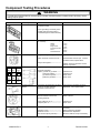
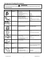
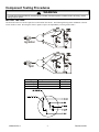
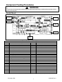
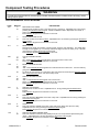
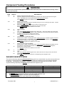
Technical Information – Top Load Washer
MAT12PDAA*, MAT12PRAA*, MAT12PSAA*
• Due to possibility of personal injury or property damage, always contact an authorized technician for servicing or
repair of this unit.
• Refer to Service Manual 16022842 for detailed installation, operating, testing, troubleshooting, and disassembly
instructions.
!
CAUTION
All safety information must be followed as provided in Service Manual 16022842
!
WARNING
To avoid risk of electrical shock, personal injury or death; disconnect power to washer before servicing, unless
testing requires power.
Models
Power Source
Voltage AC
Fuse Requirement
Frequency
Motor HP (single-phase, reversible)
Cabinet Dimensions
Height Overall (including lid open)
Height of Machine
Width
Depth
Weight
Crated (lbs/kg)
Uncrated (lbs/kg)
Water Temperatures
Water Levels
Overall Gallons (liters)
Adjustable Gallons (liters)
Inlet Hose Length
Drain Hose Length
Tub Capacity cubic feet (cubic meters)
Inner Tub (spin speed)
Agitation Speed (oscillations per minute)
December 2003
MAT12PDAA*, MAT12PRAA*, MAT12PSAA*
120 VAC
15 Amp
60 Hz
1/2 HP
52” (132.1 cm)
44-7/8” (114 cm)
25-1/2” (64.8 cm)
26-3/4” (67.9 cm)
224-lbs (102-kg)
198-lbs (90-kg)
3
2
31.5 (119.2)
29 (109.0)
4 feet (1.22 m.)
4 feet (1.22 m.)
2.5 cu.ft (0.07 cu.m.)
618 r.p.m.
150 o.p.m.
1
16022843 Rev 0
Component Testing Procedures
!
WARNING
To avoid risk of electrical shock, personal injury or death; disconnect power to washer before servicing, unless
testing requires power.
Illustration
Component
Control Board
Test Procedure
Voltage and Edge Board Pin
Connection Points
Results
See Control Board Section
Proper grounding is necessary when
handling microprocessor board to
prevent damage from static electricity.
Touch Pad
Depress the proper button, checking
for continuity.
Whites
Colors
Bright colors
Permanent Press
Wool
Delicate & Knits
Motor Relay
Reversing Relay
1
2
3
WH
L2
RD
4
5
6
RD
7
YL
RD
WH
8
9
BR
BU
A
B
PU
GY
1 to 3
1 to 2
1 to 4
5 to 3
5 to 2
5 to 4
Relay Coil: Grey to Orange/Black ------
Approx 350 – 450 Ω
Switch Terminals: Common to N.O.----
Internal switch circuit is open. If switch
is welded closed, replace switch.
Relay Coil Energized----------------------Relay coil: Purple and Gray (A to B)----
24VDC. Check for signal from control
board if not present.
Approximately 350 – 450 Ω
Terminals and Wires:
Agitate (1) White to (7) Yellow---------(3) Red to (9) Blue--------------(7) Yellow to (4) Red------------(9) Blue to (6) White-------------
Closed circuit
Closed circuit
Open circuit
Open circuit
Vault and Service
Switch
Disconnect wire terminals from switch.
Check for continuity between
terminals: Common to N.O.
Circuit is open until switch plunger is
depressed. If not, replace switch.
Pressure Switch
Disconnect wire terminals from switch.
Measure resistance across the
following terminals:
Resistance above 2 Ω indicates dirty
switch contacts.
Empty (Filling) 20 to 15-------------------Full (Run) 20 to 15 -------------------------
Closed circuit
Open circuit
Check for coin Movement.
Restricted: Clean and adjust if
necessary.
Adjust guide rail if necessary.
Examine Pinch adjustment.
Bend two deflector scoops if necessary.
Coin Drop
Diameter of Coin---------------------------Thickness of Coin--------------------------Rear of Chute (Penny Window)----------
16022843 Rev 0
Continuity, if not replace.
2
December 2003
Component Testing Procedures
!
WARNING
To avoid risk of electrical shock, personal injury or death; disconnect power to washer before servicing, unless
testing requires power.
Illustration
Component
Step-Down
Transformer
Coin sensor
Test Procedure
Check voltage.
Primary Side:--------------------------------Secondary Side:
White/Orange to White/Orange-------White/Orange to Blue-------------------Yellow to Yellow--------------------------Pink to Pink--------------------------------Check for coin registering.
Coin Sensor Voltage Checks:
1) Blocked- White to Red----------------2) Unblocked- White to Red-------------3) Continuously- Blue to White /Blue---
Results
120 VAC
3.8 VAC
1.6 VAC
20.7 VAC
22.6 VAC
Display flashes an “*” in “Service Mode”.
23 VDC
0.6 VDC
1.5VDC Replace sensor if voltage is
23VDC (Open Diode), or 0 VDC (Shorted
Diode),
Approximately 850-950 Ω
Water Valve
Measure resistance across the
terminals of each coil on the valve.
Motor
Type of Motor:
Single speed (Split phase)
See “Motor Testing” section for
correct wiring contact
Pump
Verify drain pump is not clogged or
damaged.
1) Remove clog and verify proper
operation.
2) Replace drain pump if damaged
Transmission
Belts
Lid Switch prior to
series 15
Lid Switch series 15
and later
Type of transmission (orbital):
618 r.p.m. Spin
150 o.p.m. Agitate
Refer to section on “Transmission”
Disassembly Procedures in base
manual.
Check wattage with full tub of water
only (Use Wattage Meter)
Check belt for excessive wear or being
burnt and cracking.
380 to 420 watts
Fuse 4 Amp
No continuity replace fuse.
Switch
1) Open circuit until switch is depressed.
2) If circuit is closed, check for welded
contacts and replace switch.
Check for Continuity between the
following terminals:
Line to Machine (Lid Open) -------------Line to Motor (Lid Closed)---------------Line to Machine (Lid open or Closed)--
December 2003
Replace if belt if damaged.
3
Closed Circuit
Closed Circuit
Closed Circuit, If not replace lid switch.
16022843 Rev 0
Component Testing Procedures
!
WARNING
To avoid risk of electrical shock, personal injury or death; disconnect power to washer before servicing, unless
testing requires power.
MOTOR TESTING
All four leads of the test cord are required to test the washer drive motor. The following drawings show installation of the test
cord on the drive motor. Reversing the motor to agitate or spin is accomplished by reversing wires B and C.
Agitation
Spin
Windings
Run Winding
Start Winding
Over-load
16022843 Rev 0
Wiring Harness Connections
Red to White or Black
Yellow to Blue
White to Black
4
Readings
1.5Ω
3Ω
0Ω
December 2003
Component Testing Procedures
!
WARNING
To avoid risk of electrical shock, personal injury or death; disconnect power to washer before servicing, unless
testing requires power.
Control Board
EE
Connection
CC
Connection
DD
Connection
BB
Connection
FF
Connection
AA
Connection
Connection Pin and Description
AA
AA1
AA2
AA3
AA4
AA5
AA6
AA7
AA8
AA9
AA10
Board Power Source & Relays
3.8 VAC (AA1 to AA2) (7.6 VAC AA1 to AA5)
Center Tap
22.6 VAC (AA3 to AA4)
22.6 VAC (AA4 to AA3)
3.8 VAC (AA5 to AA2) 7.6 VAC (AA1 to AA5)
20.7 VAC (AA6 to AA7)
20.7 VAC (AA& to AA6)
Motor relay 24VDC (AA8 to AA9)
25VDC
Reversing Relay 24 VDC
CC
CC1
CC2
CC3
CC4
CC5
CC6
Switches and Coin Sensor #1
--Service Door Switch Sense
Coin 1
Coin1 Photodiode
Vault Switch Sense
DD
DD1
DD2
DD3
DD4
Coin Sensor #2
Coin 2 Photodiode
-Coin 2
--
BB
Component Sensors & Line Voltage
BB1
25VDC (BB1 to EE4)
BB2
Cold Water Valve
EE
Battery
BB3
Hot Water Valve
EE1
+ 4.5VDC (EE1 to EE4)
BB4
-EE2
-BB5
120 Line / Pressure Switch
EE3
-BB6
Washer Motor Sense
EE4
− Ground 4.5VDC (EE4 to EE1)
BB7
Lid Switch
BB8
120 Neutral
FF
Coin and Vault Switch Sensor
BB9
-FF1
-BB10
-FF2
25VDC
BB11
-FF3
-Note: Component side of the microprocessor board, the connector pins are read left to right (except the battery connector EE).
December 2003
5
16022843 Rev 0
Component Testing Procedures
!
WARNING
To avoid risk of electrical shock, personal injury or death; disconnect power to washer before servicing, unless
testing requires power.
PROGRAMMING PROCEDURES
CODE
607
DISPLAY
6
07
710
7
10
WASH & AGITATION CYCLE
This is the number of minutes for Wash. Adjustable from 8-15 minutes by pressing the Permanent
Press keypad.
Press Woolens keypad once to advance to next code.
811
8
RINSE CYCLES
Represents the length and number of rinses (except “woolens” and “delicates”). The middle digit
is length of rinse agitation (1 to 4 minutes) and the last digit is number of rinses (1or 2). Advance
rinse option by pressing Permanent Press keypad.
Press Woolens keypad once to advance to next code.
900
9
00
OC
CYCLE COUNTER OPTION
“OFF."
ON." Press Delicates & Knits keypad three consecutive times to select "OC".
Press Woolens keypad once to advance to next code.
1.00
1.
00
0C
MONEY COUNTER OPTION
“OFF”
“ON”. Press Delicates & Knits keypad three consecutive times to select "OC". Counter resets by
going from “OFF” to “ON”.
To select “On” and not turn off. First select “ON”, then within two seconds press Delicates & Knits
twice, Permanent Press Once, and exit the setup mode.
C0
EXPLANATION
REGULAR CYCLE PRICE
Represents the number of coins. See value of Coin 1 and Coin 2. Adjustable from 0-39 coins by
pressing the Permanent Press keypad. NOTE: PS MODELS ONLY- Represent the number of
push-in actuations of the coin slide.
Press Woolens keypad once to advance to next code.
2.00
2.
00
SP
SPECIAL PRICING OPTION.
"OFF."
"ON." Press Delicates & Knits keypad once to select "SP."
Steps "3." thru "9." codes are skipped if mode "2.00" is selected.
Press Woolens keypad once to advance to next code.
3.07
3.
07
SPECIAL CYCLE PRICE
Represents the number of coins. Adjustable from 0 - 99 by pressing the Permanent Press
keypad.
Press Woolens keypad once to advance to next code.
5.00
5.
00
MINUTES
This is the selection "MINUTES" of the time of day clock. Adjustable from 0 to 59 by pressing the
Permanent Press keypad.
Press Woolens keypad once to advance to next code.
6.00
6.
00
HOUR
This is the selection "HOUR" of the time of day clock using military time (24 hour clock).
Adjustable from 0 to 23 by pressing the Permanent Press keypad.
Press Woolens keypad once to advance to next code.
7.00
7.
00
SPECIAL PRICING STARTING HOUR
This is the selection of the hour using military time (24 hour clock) that the Special Pricing will
"begin “. Adjustable from 0 to 23 by pressing the Permanent Press keypad.
Press Woolens keypad once to advance to next code.
16022843 Rev 0
6
December 2003
Component Testing Procedures
!
WARNING
To avoid risk of electrical shock, personal injury or death; disconnect power to washer before servicing, unless
testing requires power.
CODE
8.00
DISPLAY
8.
00
9.10
9.
10
A.00
A.
00
SC
b.05
b.
05
C.20
C.
20
d.00
d.
00
CS
EXPLANANTION
SPECIAL PRICING STOPPING HOUR
This is the selection of the hour using military time (24 hour clock) that the Special Pricing will
"stop." Adjustable from 0 to 23 by pressing the Permanent Press keypad.
Press Woolens keypad once to advance to next code.
SPECIAL PRICE DAYS
Represents the day of the week and if special pricing is to occur on that day of the week. The last
digit is "0" for OFF or "S" for ON.
Press the Delicates & Knits keypad once to select "0" and once for "S."
Press Permanent Press keypad to advance to next day of the week.
Press Woolens keypad once to advance to next code.
VAULT VIEWING
"OFF."
"ON." Press Delicates & Knits keypad once to select "SC." The money and/or cycle counter will
be viewable when the vault is opened. If "00" is selected, the service door will need to be opened
to activate, to view the money and/or cycle counter.
Press Woolens keypad once to advance to next code.
VALUE OF COIN 1 (QUARTER DROP)
Represents the number of nickels given to the value of each coin in code 607 "regular cycle price"
or "special cycle price." For example: b.05 equals five nickels or one quarter. Press Permanent
Press keypad to advance from 1 to 99 in nickels.
Press Woolens keypad once to advance to next code.
VALUE OF COIN 2 (DOLLAR DROP)
Represents the number of nickels given to the value of each Dollar dropped in the dollar coin slot.
For example: C.20 equals twenty nickels or one dollar. Press Permanent Press keypad to
advance from 1 to 99 in nickels.
Press Woolens keypad once to advance to next code.
COIN SLIDE OPTION
"OFF."
"ON." Press Delicates & Knits keypad once to select "00" when coin drop is used, and "CS" for
models not using coin drops.
Press Woolens keypad once to advance to the beginning of the program mode.
WASHER DIAGNOSTIC MODE
The mode is entered by depressing Delicates & Knits keypad for one second while in any of the set-up modes one
through six or with a diagnostic code present. Diagnostic codes are cleared on entry and all display segments
should flash. If a diagnostic code persists, it must be corrected before the diagnostic cycle will start. With all
segments flashing, depressing the Woolens keypad starts the diagnostic cycle.
Display
Function
C
Cold Fill
H
Hot Fill
A
Agitation
S
Spin
Note: 1) Woolens keypad can be used to pause/resume the diagnostic cycle.
2) Delicate & Knits keypad will cancel the cycle and exit the diagnostic mode.
3) Permanent Press keypad, “CC”(Free cycle) will be displayed.
When you exit the service mode “Select Cycle” will be displayed
December 2003
7
Time Length
3 seconds
3 seconds
3 seconds
10 seconds
16022843 Rev 0
Component Testing Procedures
!
WARNING
To avoid risk of electrical shock, personal injury or death; disconnect power to washer before servicing, unless
testing requires power.
Washer
diagnostic
Program
No user program
should be in progress.
The lid should be
closed and the washer
tub should be empty
before running this test.
Enter operator mode
using service switch.
Push the delicates and
knits program keypad for
more than one second.
If any segments of
display are not working,
replace the control
board.
Does cold water run
when an "C" is in the
display?
Does hot water run
when an "C" is in the
display?
Push the woolens
program keypad to start
the diagnostic program.
Push the woolens
program keypad to stop /
start the diagnostics in the
current phase.
No
The hoses may be
crossed or the water
valve miswired.
Yes
No
Yes
If washer will not fill,
agitate or spin, unplug
washer and check for
continuity of lid switch.
Does switch check
closed with lid closed?
No
Adjust lid switch or
replace switch if
necessary.
Yes
Does hot water run
when an "H" is in the
display?
Push the woolens
program keypad to stop /
start the diagnostics in the
current phase.
No
Yes
16022843 Rev 0
8
Check water shutoff
valves, filter screens
and hose routing.
December 2003
Component Testing Procedures
!
WARNING
To avoid risk of electrical shock, personal injury or death; disconnect power to washer before servicing, unless
testing requires power.
Check wiring and
terminations between
water valves, pressure
switch and control board.
Remove connector BB.
Does 115VAC appear
between the black and red
wires on connector BB?
Replace pressure
switch or hose.
No
Yes
Does 115VAC appear
between the blue / black
and red wires (cold water
check) or orange and red
wires (hot water check)
on the control board edge
connector BB?
Replace control
board.
No
Yes
Replace water
valve.
Does washer agitate
when an "A" is in the
display?
No
Push the woolens
program keypad to stop /
start the diagnostics in the
current phase.
Does washer spin
when an "A" is in the
display?
Yes
Check wiring and
terminations between
control board, motor relay
and motor. Make sure
motor is not bad or tripped
out on thermal protection.
Does 25 VDC appear
between X on control
board edge connector and
a control board mounting
nut?
No
Yes
Replace control
board.
No
Replace reversing
relay.
Yes
Does 25 VDC appear
between V on control
board edge connector and
a control board mounting
nut?
Replace control
board.
December 2003
Yes
9
No
Replace motor
relay.
16022843 Rev 0
Component Testing Procedures
!
WARNING
To avoid risk of electrical shock, personal injury or death; disconnect power to washer before servicing, unless
testing requires power.
Does washer spin when
an "S" is in the
display?
No
Check wiring and
terminations between the
control board and spin
relay. Make sure motor is
not bad or tripped out on
thermal protector.
Push the woolens
program keypad to stop /
start the diagnostics in the
current phase.
No
Yes
Washer check ok.
Does 25 VDC appear
between X on control
board edge connector and
a control board mounting
nut?
Yes
Replace reversing
relay.
No
If desired push the
delicates and knits
program key pad to cancel
the diagnostic program.
Exit operator mode
using service switch.
Replace control
board.
WASHER HELP CODES
Code
20
21
22
Problem
Filling too quickly during cycle
Losing water during cycle (siphoning)
Losing water during cycle (siphoning)
Description
Pressure switch opens sooner then expected
Added more water during agitations cycle
Added more water during soaking cycle
WASHER FAULT CODES
Fault Codes
F1
F4
F5
F7
F8
F9
F12
F13
16022843 Rev 0
Description
Water level circuit failure on control board (machine non functional)
Lid switch circuit failure on control board (machine non functional)
Blocked coin 1 or coin drop control circuit failure (machine non functional)
Slow fill detected; fill time greater than 5 minutes (machine functional)
Slow drain detected; drain time greater than 2 minutes (machine functional))
Low voltage detected; less than 90 volts AC (machine functional)
Motor sensor circuit failure on control board (machine functional)
Blocked coin 2 or coin drop control circuit failure (machine non-functional)
10
December 2003
Component Testing Procedures
!
WARNING
To avoid risk of electrical shock, personal injury or death; disconnect power to washer before servicing, unless
testing requires power.
F1
Try to clear diagnostic
code by pushing delicate
and knits keypad for one
second.
Yes
Did diagnostic code
cancel?
No
F4
Try to clear diagnostic
code by pushing delicate
and knits keypad for one
second.
Replace control board.
Yes
Did diagnostic code
cancel?
No
F5
Check wiring and
terminations between
first coin drop and
control board.
F7
Check for plugged
screen on fill hoses.
F8
Check drain hose for
being plugged or kinked.
F9
Check for object blocking
first coin drop optic
sensor. Then check
transformer for loss of 24
circuit..
Replace first coin drop
optic sensor if F5 still
appears in display.
This diagnostic code will appear routinely
if washer fills slowly and may be ignored if
the water pressure is very low.
This failure code will
appear routinely if
washer drains slowly.
Check pump belt for
proper tension.
This diagnostic code indicates a
low voltage condition has occurred.
check installation to insure proper
power to washer.
Try to clear diagnostic code by
pushing delicate and knits keypad
for one second.
False diagnostic indication.
Control board is ok.
Replace control board.
False failure indication
control board is ok.
Yes
F12
False diagnostic indication.
Control board is ok.
This failure does not affect the
operation of the control. It will only
affect no run counts in an Accutrac
environment. It can be corrected by
replacing the control board.
Did failure code cancel?
No
F13
December 2003
Check wiring and terminations
between second coin drop and
control board.
Check for object blocking
second coin drop optic
sensor.
11
Yes
Replace second coin drop
optic sensor if F13 still
appears in display.
16022843 Rev 0
Component Testing Procedures
!
WARNING
To avoid risk of electrical shock, personal injury or death; disconnect power to washer before servicing, unless
testing requires power.
TROUBLESHOOTING CONTROL BOARD FLOW CHART
Display is
Blank
Enter operator mode
using service switch.
Does display contain a
diagnostic code?
Make sure washer
is plugged in to
live power source
Enter diagnostic
code trouble
shooting guide
Yes
No
Plug in washer. Does 25
VDC appear between W on
the control board edge
connector and a control
board mounting nut.
Unplug washer and check
wiring and termination
between transformer, service
switch and control board
No
Yes
Does 115 VAC
appear across the
primary of the
transformer?
Does 3.8 VAC
appear between S
on O on the
control board edge
connector?
No
Check wiring to
transformer and
power at outlet
Initiate the manual
reset sequence
Replace the transformer.
Inspect control board for
burned components and
replace it if damaged.
Shorted diodes will
damage new transformer.
If problem still
exists replace
control board
Abnormal
display or
function
16022843 Rev 0
Initiate the manual
reset sequence
Yes
Clean lint off of
control board
display wires.
12
If problem still
exists replace
control board
December 2003
Component Testing Procedures
!
WARNING
To avoid risk of electrical shock, personal injury or death; disconnect power to washer before servicing, unless
testing requires power.
Washer stuck
with 0 minutes
remaining in
display
Lift washer lid. Did
display change?
Yes
The washer lid must be
opened after a program
ends before the washer
will operate again
Yes
Check wiring and
termination between lid
switch and control board
No
Unplug washer
and check
continuity of lid
switch as lid is
raised and lowered
Does lid switch
open and close
properly? Is lid
switch wet?
Plug in washer. If
problem still exists
replace control
board
No
Adjust lid switch or
replace it if
necessary
Control does not
respond to
program key
inputs
Does display show
"select cycle"?
Check touch pad in service
mode. Does control board
respond? Unplug washer
and check membrane switch
tail connection. Plug washer
back in .
Yes
If problem still exist
replace membrane
switch
No
Put proper number
of coins into coin
drop
December 2003
If problem still
exist replace
control board
13
16022843 Rev 0
Component Testing Procedures
!
WARNING
To avoid risk of electrical shock, personal injury or death; disconnect power to washer before servicing, unless
testing requires power.
Will not respond
to MEQ
Does MEQ
respond to other
machines?
Check optic
window for
obstructions, dirt,
or scratches.
Yes
No
If problem still
exists replace
control board
MEQ has failed.
No response to
coin 1
Is display blank?
Is coin slide option
selected?
No
Yes
No
See blank display
section in trouble
shooting guide
Check the coin
mechanism for
proper adjustment.
Yes
Timings for the coin
slide mode will cause
coins to not be
recognized. Deselect
the coin slide mode.
Check wiring and
termination between first
coin drop and control
board
Check lighting. Too
much ambient light in
the coin drop will cause
coins not to be
recognized.
No
Yes
Reconnect
connector and
plug in washer
If problem still
exist replace
control board
If problem still
exists replace first
coin optic sensor
16022843 Rev 0
Unplug washer and
connector CC and check
resistance between the
red wire and the white
wire in connector CC. Is
resistance greater than
10K ohms?
14
December 2003
Component Testing Procedures
!
WARNING
To avoid risk of electrical shock, personal injury or death; disconnect power to washer before servicing, unless
testing requires power.
No response to
coin 2
Is display blank?
Check the coin
mechanism for
proper adjustment.
No
Yes
Check wiring and
termination between
second coin drop and
control board
See blank display
section in trouble
shooting guide
Check lighting. Too
much ambient light in
the coin drop will cause
coins not to be
recognized.
Unplug washer and
connector CC and check
resistance between the
red wire and the white
wire in connector CC. Is
resistance greater than
10K ohms?
No
Yes
If problem still
exists replace
second coin optic
sensor
Will not keep
time of day
during power
interruptions
Is a battery
installed?
Reconnect
connector and
plug in washer
If problem still
exist replace
control board
Does greater than 3.4 VDC
appear between the red and
black wires of the battery?
Yes
No
Replace battery
No
Yes
A battery must be
installed in order to keep
time of day during power
interruptions.
Check battery
connector and
terminations
If problem still
exists replace
control board
December 2003
15
16022843 Rev 0
Component Testing Procedures
!
WARNING
To avoid risk of electrical shock, personal injury or death; disconnect power to washer before servicing, unless
testing requires power.
"Unbalance"
stays in display
Unplug washer check
wiring and terminations
between lid switch and
control board
Adjust lid switch or
replace it if
necessary
Cannot enter or
cannot exit operator
mode
Check continuity of
lid switch as lid is
raised and lowered
Does switch open
and close
properly?
No
Plug in washer
replace control board
if problem still exists
Yes
Check wiring and
terminations between
service switch and control
board
Check for proper
adjustment of service
switch
Unplug washer and connectors
CC and FF. Check for continuity
between yellow wire on
connector CC and orange wire
on connector FF while cycling
service switch.
Replace control
board
Operator options
revert to defaults
16022843 Rev 0
Yes
Setup operator options as
desired unplug washer for
2 minutes then plug in
washer
Does service switch
open and close
properly?
No
Replace service
switch
If problem still exists
replace control board
16
December 2003
Component Testing Procedures
!
WARNING
To avoid risk of electrical shock, personal injury or death; disconnect power to washer before servicing, unless
testing requires power.
Display flashes in
user Mode
Water runs
without program
selected
Unplug washer and connector CC
and FF. Check for continuity
between yellow/black wire on
connector CC and orange wire on
connector FF while cycling vault
switch
Check wiring and
terminations between
vault switch and control
board
Check for proper
adjustment of
vault switch
Replace control
board
Yes
Does vault switch
open and close
properly?
Unplug washer.
Does water still
run?
No
Check wiring and
terminations between
control board and water
valve
No
Replace vault
switch
If problem still
exists replace
control board
Yes
Replace water
valve
No hot water or
cold water
Spin instead of
agitating
No spin or
agitate
December 2003
Run washer
diagnostics
program
Run washer
diagnostics
program
Run washer
diagnostics
program
17
16022843 Rev 0
Wiring Diagram
!
WARNING
To avoid risk of electrical shock, personal injury or death; disconnect power to washer before servicing, unless
testing requires power.
MAT12PDA**, MAT12PSA** SCHEMATIC
COIN SENSOR #2
(OPTIONAL)
WBU WH
RD BU
CONNECTOR DD
COIN
SENSOR
W-BU
WH
OR
OR
VAULT
SWITCH
Y-BK
RD
Y-BK
BU
6 2166350
16022843 Rev 0
18
December 2003
Wiring Diagram
!
WARNING
To avoid risk of electrical shock, personal injury or death; disconnect power to washer before servicing, unless
testing requires power.
MAT12PRA** SCHEMATIC
December 2003
19
16022843 Rev 0