1
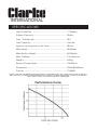
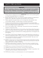
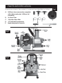
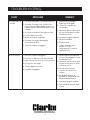
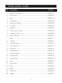
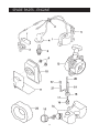
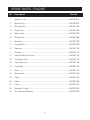
ENGINE DRIVEN
WATER
R PUMP
Model No. CM1
OPERATING & MAINTENANCE
INSTRUCTIONS
0603
SPECIFICATIONS
Inlet/Outlet dia. .......................................................... 1" (25mm)
Engine Capacity ........................................................ 25.6cc
Fuel, 2-stroke mix ........................................................ 25:1
Fuel Capacity ............................................................. 0.6 Litre
Approx. running time on full tank ............................. 45 min
Max Head .................................................................... 35 Metres
Max Suction Height .................................................... 8.0 Metres
Max. Delivery .............................................................. 115 litres/min
Weight .......................................................................... 4.5 kg
Spound Power Level .................................................. 104 dBLWA
Dimensions .................................................................. 315x225x340mm
Part No. ........................................................................ 7140630
Please note that the details and specifications contained herein, are correct at the time of going to
print. However, CLARKE International reserve the right to change specifications at any time without
prior notice. Always consult the machine’s data plate
Performance Curve
2
Thank you for purchasing this Clarke Water Pump.
This pumps is designed for pumping clean water ONLY. The pump is NOT
self-priming, please see Installation instructions.
The suction strainer supplied, must always be used, to ensure that stones or other
objects cannot be drawn up, as this would cause severe damage to the pump.
CAUTION! NEVER use for pumping solids in suspension - slurry, sludge, sand, or
mud etc.
Please read this leaflet thoroughly and follow the instructions carefully, in doing so
you will ensure the safety of yourself and that of others around you, and with
correct handling and servicing, you can look forward to the pump giving you
long and satisfactory service.
GUARANTEE
This CLARKE product is guaranteed against faulty manufacture for a period
of 12 months from the date of purchase. Please keep your receipt which
will be required as proof of purchase.
This guarantee is invalid if the product is found to have been abused or
tampered with in any way, or not used for the purpose for which it was
intended.
Faulty goods should be returned to their place of purchase. No product
can be returned to us without prior permission.
This guarantee does not effect your statutory rights.
3
SAFETY PRECAUTIONS
WARNING
As with all machinery, there are certain hazards involved with their operation
and use. Exercising respect and caution will considerably lessen the risk of
personal injury. However, if normal safety precautions are overlooked, or
ignored, personal injury to the operator, or damage to property may result.
1.
These pumps are designed to pump WATER ONLY. Never use for pumping petrol
(or other flammable liquids), or chemicals.
2.
Before operating this pump, you should thoroughly familiarise yourself with all
aspects of its’ operation, and follow all instructions in this manual.
3.
Never operate an engine driven unit in an explosive atmosphere, near
combustible materials, or where there is insufficient ventilation.
4.
Always ensure that the pump is properly secured and anchored where
necessary to prevent it from moving during operation, and that the immediate
area surrounding the pump is kept clear.
5.
Do not over tighten drain or filler plugs. Excessive force may damage the
threads or the pump body.
6.
Observe all safety precautions for the handling of fuel. Never refuel the engine
whilst it is running, and allow the engine to cool sufficiently before refuelling.
7.
Whenever carrying out maintenance or making adjustments, the engine must
be stopped.
8.
Use at least 1ft (3OOmm) of flexible hose to make plumbing connections to
the pump. Rigid piping will put stress on the pump, causing eventual damage.
9.
Use only replacement parts supplied by the manufacturer. The use of non
standard parts could be hazardous.
10. NEVER run the pump dry. Always fill the pump body with water before starting.
When in regular use, it is not necessary to drain the pump body each time it is
used, unless there is danger of freezing
11. ALWAYS use the strainer connected to the suction hose, to prevent stones
and other solids from being drawn up, which could cause severe damage.
12. NEVER carry or transport the pump with the engine running.
13. ALWAYS check the pump for loose or missing screws before use.
14. Take great care when handling the pump after it has been in operation, the
cylinder head and silencer will become very hot.
15. NEVER allow children or untrained persons to use this equipment.
4
PARTS IDENTIFICATION
Unpack and check the contents. Loose parts are identified as follows:
A. 2x25mm hose connectors complete
with rubber seals, plus 1x20mm tail
connector
B.
3x Hose Clips
C. 1xSuction hose filter
D.
1xCrosshead screwdriver
E.
Spark plug socket wrench
Fig.2
Fig.3
Fig.1
PREPARING THE PUMP FOR OPERATION
A. GENERAL.
Always prepare the site beforehand.
Ensure there is an adequate, firm foundation on which the pump may be located,
and as near the water source as possible.
Ensure there is adequate drainage for the discharged water, and that there is no
danger of damage to property as a result of the pumping operation.
B. THE ENGINE.
Fill the fuel tank with fuel as follows:
Mix: 25 parts Unleaded Petrol to 1 part 2-Stroke Oil
25:1
Use Clarke 2 stroke oil....Part No.3050870
1.
2.
WARNING:
Observe ALL necessary precautions when handling petrol.
z
Never run the engine in an enclosed space - ensure there is adequate
ventilation.
C. THE PUMP
1.
Place the unit on a firm level foundation, putting it as near as possible to the
water source, and ensure it is anchored where necessary, to prevent it from
moving during operation.
2.
Connect the suction hose to the inlet port, using the adapter provided, ensuring
the rubber seal is in place.
NOTE: 25mm or 20mm ID hose may be used...appropriate connectors are provided.
The hose must be completely sound, there must be no damage of any kind.
The connection at the pump body, and all other connections, should there
be any, must be air tight.
Hoses or pipes should he supported independently and not carried by the
pump.
Flexible hose MUST be used at the pump connections
IMPORTANT : An air leak in the suction line will reduce the capacity of the pump.
The vast majority of problems which may occur, are as a result of air leaks in the
suction line.
6
Pay particular attention to the following:
3.
a.
Use sealant on all threaded connections.
b.
Always ensure the rubber seal is in place and correctly fitted.
c.
Always use a flexible hose at the pump body connection, of at least
1ft (300mm).
d.
Keep all pipes/hoses as short and straight as possible, and avoid sharp
bends.
e.
If a flexible hose must he laid across a roadway, protect it with
planking. (Instantaneous shut off pressure, applied when a vehicle
runs across an unprotected hose, will cause “hydraulic shock”, which
can damage the pump and/or the hose).
The suction strainer MUST be attached to the end of suction hose, to prevent
large stones etc., from being drawn up which could cause severe damage.
Keep the strainer clean. If it is likely to clog with dirt or debris, proceed as
follows:
a. Prepare a bed of stones on which to rest the strainer.
or b. Tie the strainer so that it stays off the bottom of the pit, pond or excavation.
or c. Tie the strainer inside a basket or bucket.
4.
Remove the Priming Plug, on top of the pump case, and fill the pump and
suction hose with water, leaving no air gap.
Remember the pump is self-priming ONLY when it has been filled. Once filled,
a non-return valve will maintain water within the pump body should it be
necessary to stop the motor (for refuelling etc.). Priming is ONLY necessary
therefore when the pump has been drained.
5.
Ensuring there is adequate drainage for the discharged water, attach the
discharge hose using a 25mm ID hose.
ALWAYS check to ensure the delivery hose is adequately supported, and
protected to avoid, for example, the possibility of vehicles passing over it,
which could damage both the hose AND the pump.
Properly fuelled and connected, your pump will run without attention for
approximately 45 minutes on a full fuel tank.
7
OPERATION
Ensuring the site, and pump is prepared as detailed on pages 5 & 6, proceed as
follows:
Fig.4
1. STARTING.
Ensuring there is sufficient fuel in the tank,
press the priming pump, see illustration
opposite, at least 10 times.
NOTE: This is NOT necessary if the unit has
not previously been drained of fuel.
1.1 Set the choke lever to ‘Start’, see Fig.5.
If the engine is warm, set to ‘Normal
Running position.....
If the engine and ambience is cold,
set to ‘Cold Start’ position.....
1.2 Set the Throttle to approximately half open...midway between cold start and normal.
1.3 Switch ON at the ON/OFF switch.
Fig.5
1.4 Hold down the pump and pull the starter
recoil rope firmly until the engine starts.
IMPORTANT: Do not snatch at the starter rope, and
allow it to retract slowly after each pull.
1.5 Once the engine starts, set the choke
progressively to the ‘Normal Running position’,
and the engine throttle to a low speed setting,
and allow to run for about 1 minute.
NEVER set the throttle to a high speed position
until the engine has warmed up.
2. CONTROLS.
On high suction lifts, a higher engine speed is necessary than on low lifts. On shallow
lifts therefore, or when there is little water to pump, preserve fuel and engine wear,
by reducing engine speed. NEVER run at an unnecessarily high speed.
3. STOPPING.
GRADUALLY reduce engine speed to minimum, and stop the engine by switching
OFF the ignition switch.
4. BLOCKAGES
In the event of blockages, where debris has entered the suction chamber, remove the
suction chamber bolts, disconnect the suction hose and flush out the pump body.
8
MAINTENANCE
DAILY, before use.
Check for any loose bolts/screws, or leaking fuel and rectify before proceeding.
Ensure there is sufficient fuel in the tank.
MONTHLY or every 20 Hours
Clean the Air Filter as follows:
Remove centre screw and pull off the air filter cover.
Remove sponge filter and wash in warm soapy water. Rinse thoroughly and allow
to dry before reassembling.
6 MONTHLY or every 50 hours
Ensure the engine is cold before performing the following tasks.
1.
Clean and adjust the Spark Plug:
Pull off the spark plug lead and, using the socket wrench supplied, unscrew
and remove the spark plug.
Clean using a wire brush. When all carbon has been removed, adjust the gap
to 0.6 - 0.7mm, using an appropriate gauge, available from all tool retailers.
2.
Clean the Fuel Filter:
Remove the fuel filler cap completely, then, using
a piece of wire with a hooked end, pull out the fuel
filter and hose, as shown in Fig.6.
Fig.6
Clean the filter thoroughly using clean petrol. If it is badly
contaminated, renew it.
Before reinstalling the filter, clean out the fuel tank,
ensuring there is no sediment collecting in the bottom.
STORAGE:
Should the pump be stored for any period, you should proceed as follows:
Once the engine has cooled, disconnect all hoses and remove the pump drain
plug, Drain the pump completely, and, importantly, flush with CLEAN water
thoroughly, then replace the drain plug.
Drain the fuel tank completely, then, start the engine in the normal manner and
allow it to run until it stops due to lack of fuel.
NOTE: If prolonged storage is probable, fuel could congeal, causing the
components to ‘gum up’, which would be very problematic.
Remove the spark plug and pour in a teaspoonful of engine oil, then, gently pull
the recoil starter a few times so that the oil is deposited on the cylinder walls,
before replacing the spark plug.
Store the pump, preferably under cover, not exposed to the elements, and in a
clean dry environment.
9
TROUBLESHOOTING
FAULT
A) Pump fails to
prime
PROBLEM
REMEDY
1. Priming chamber not filled correctly.
2. Air leaks through the suction line
joints (broken/damaged screws or,
rubber hoses, loose or broken hose
clamps
3. Suction or delivery line obstructed
4. Pump speed too low.
5. Worn or broken impeller.
6. Air leaks through damaged
mechanical seal.
B) Low output
1. Fill priming chamber
leaving no air gap.
2. Carry out repairs as
necessary
3. Remove obstruction and
ensure there are no kinks
in delivery line.
4. Increase engine speed.
5. Renew Impeller.
6. Renew Seal.
7. Suction strainer clogged
7. Clean strainer, and
ensure it is not
submerged in mud or
sediment etc.
1. Suction strainer clogged.
1. Clean strainer, and ensure
it is not sub merged in mud
or sediment etc.
2. Suction or delivery line obstructed
3. High friction losses in the suction line.
4. Suction lift too high.
5. Pump speed too low.
2. Remove obstruction and
ensure there are no kinks
in delivery line.
3. Avoid unnecessary
curves, restrictions or
valves.
6. Impeller clogged.
4. Set pump as near as
possible to the level of the
liquid to be pumped.
5. Increase engine speed.
6. Disassemble pump, and
clean.
10
SPARE PARTS -PUMP
12
SPARE PARTS -PUMP
No.
Description
Part No.
1
Engine Complete ...................................................................... DSCM101
2
End Cover .................................................................................. DSCM102
3
Bolt .............................................................................................. DSCM103
4
Al. Washer .................................................................................. DSCM104
5
Mechanical Seal ....................................................................... DSCM105
6
Packing ...................................................................................... DSCM106
7
Impeller ...................................................................................... DSCM107
8
Inner Pump Casing ................................................................... DSCM108
9
Packing - Inner .......................................................................... DSCM109
10
Main Casing .............................................................................. DSCM110
11
Bolt .............................................................................................. DSCM111
12
Handle ........................................................................................ DSCM112
13
Check Valve .............................................................................. DSCM113
14
Inlet Housing .............................................................................. DSCM114
15
Hex. Bolt ..................................................................................... DSCM115
16
Rubber Seal ............................................................................... DSCM116
17
Hose Coupling ........................................................................... DSCM117
18
Locking ring ............................................................................... DSCM118
19
Priming Plug ............................................................................... DSCM119
20
Seal ............................................................................................. DSCM120
21
Drain Plug ................................................................................... DSCM121
22
Seal ............................................................................................. DSCM122
23
Base ............................................................................................ DSCM123
24
Hose Clip .................................................................................... DSCM124
25
Strainer ....................................................................................... DSCM125
13
SPARE PARTS - ENGINE
14
SPARE PARTS - ENGINE
No.
Description
Part No.
1
Ignition Coil ................................................................................ DSCM101E
2
Spark Plug .................................................................................. DSCM102E
3
Stop Switch ................................................................................ DSCM103E
4
Plug Cap .................................................................................... DSCM104E
5
Wire Laed ................................................................................... DSCM105E
6
Grommet ................................................................................... DSCM106E
7
Bracket ....................................................................................... DSCM107E
9
Flange Nut ................................................................................. DSCM109E
10
Silencer ....................................................................................... DSCM110E
11
Gasket ........................................................................................ DSCM111E
13
Recoil Starter Compl. ................................................................ DSCM113E
14
Fuel Tank Assy. ........................................................................... DSCM114E
15
Fuel Cap Assy. ........................................................................... DSCM115E
16
Fuel Filter .................................................................................... DSCM116E
17
Bush ............................................................................................ DSCM117E
18
Grommet ................................................................................... DSCM118E
19
Tube ............................................................................................ DSCM119E
20
Tube ............................................................................................ DSCM120E
21
Tube ............................................................................................ DSCM121E
22
Breather Valve ........................................................................... DSCM122E
23
Air Cleaner Element ................................................................. DSCM123E
15