1
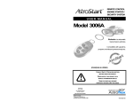
REMOTE CONTROL
ENGINE STARTER /
SECURITY SYSTEM
USER MANUAL
Model 3006
For all automatic transmission
gas- and diesel-powered vehicles.
(FRANÇAIS AU VERSO)
CONSULT SAFETY PRECAUTION SECTION
BEFORE USING THIS PRODUCT.
NEVER INSTALL THIS PRODUCT ON A
MANUAL TRANSMISSION VEHICLE.
SOME FEATURES MAY REQUIRE
ADDITIONAL MATERIAL (NOT INCLUDED).
PATENT NOS
CAN 1.130.426
USA 4.345.554 - 5.614.883
5.617.819 - 5.673.017
<P]dUPRcdaTSX]2P]PSPQh)
AND OTHER PATENTS PENDING
Litho’d
in Canada
All rights reserved © Astroflex 1998
(" ""! 0
<>34;"%
GOVERNMENT REGULATIONS
This device complies with the requirements of Industry Canada (IC) - Management of
Radiofrequencies, as specified in document CNR-210. Its use is authorized only on a no-interference,
no-protection basis; in other words, this device must not be used if it is determined that it causes
harmful interference to services authorized by IC. In addition, the user of this device must accept any radio interference
that may be received, even if this interference could affect the operation of the device.
This device complies with Part 15 of the FCC rules.
Operation is subject to the following two conditions:
(1)
this device may not cause harmful interference and
(2)
this device must accept interference that may cause undesired operation.
This equipment has been tested and found to comply with the limits for a class B digital device, pursuant to Part 15 of the
FCC Rules. These limits are designed to provide reasonable protection against harmful interference in a residential
installation. This equipment generates, uses and can radiate radio frequency energy and, if not installed and used in
accordance with the instruction manual, may cause harmful interference to radio communications. However, there is no
guarantee that interference will not occur in a particular installation. If this equipment does cause harmful interference to
radio or television, which can be determined by turning the equipment OFF and ON, the user is encouraged to try to
correct the interference by one or more of the following measures:
Reorient or relocate the receiving antenna.
Increase the separation between the equipment and receiver.
Connect the equipment into an outlet on a circuit different from that to which the receiver is connected.
Consult the dealer or an experienced radio / TV technician for help.
Warning:
Changes or modifications not expressly approved by <manufacturer> could void the user's authority to operate the
equipment.
8]R
%#A^dcT!!
Bc®[XTSz>aU^aS@dÎQTR2P]PSP
91!B
www.astroflex.com
[email protected]
4 ; 4 2 C A > = 8 2
2 > A ? $ %0 4[\ BcaTTc
< P]RWTbcTa= 7 " D B0
<>34;"%
INTRODUCTION
Thank you for choosing the Astroflex Remote Starter/Security System.
Your System is the result of intensive research by a company specializing in the design of high-quality electronic
automotive products.
It is designed to provide many years of reliable, trouble-free service.
Its advanced microchip circuitry incorporates billions of possible access codes, which makes it virtually impossible
to interfere with another remote control vehicle.
Your Remote Starter offers the ultimate in safety, is simple to use and has many features to make your life easier.
Please read the following instructions carefully so that you understand how your Remote Starter works and can
take advantage of all the features.
Some of the functions described below may not be applicable to your vehicle.
Table of contents
GOVERNMENT REGULATIONS _______________________________________________________________2
SAFETY PRECAUTIONS _____________________________________________________________________2
BEFORE USING YOUR REMOTE STARTER _____________________________________________________2
THE REMOTE CONTROL ____________________________________________________________________3
USING YOUR REMOTE CONTROL -------------------------------------------------------------------------------------------------------------------- 3
CONFIRMATION --------------------------------------------------------------------------------------------------------------------------------------- 3
BATTERY REPLACEMENT ---------------------------------------------------------------------------------------------------------------------------- 4
COMMANDS FOR 3006 ______________________________________________________________________5
START COMMANDS ----------------------------------------------------------------------------------------------------------------------------------- 6
SECURITY SYSTEM------------------------------------------------------------------------------------------------------------------------------------ 9
LOCK/UNLOCK COMMANDS ----------------------------------------------------------------------------------------------------------------------- 14
OTHER COMMANDS --------------------------------------------------------------------------------------------------------------------------------- 15
SAFETY CHECKS _________________________________________________________________________19
HOOD SWITCH --------------------------------------------------------------------------------------------------------------------------------------- 19
DETECTING “P” AND “N” GEARSHIFT POSITIONS --------------------------------------------------------------------------------------------- 19
REPLACING OR BOOSTING VEHICLE BATTERY _______________________________________________19
LIMITED LIFETIME WARRANTY ______________________________________________________________20
1
<>34;"%
SAFETY PRECAUTIONS
Before using this product, carefully read the following safety precautions.
Immediately report any malfunction to the Astroflex dealer that performed installation.
Under no circumstance can this product or its use be modified.
Always turn off main switch when vehicle is parked in an enclosed, unventilated area or is in for servicing.
Always turn off main switch when not using your Remote Starter for extended periods of time.
Keep remote controls away from children.
Have your engine tuned regularly to ensure optimum performance of your Remote Starter.
Make sure your windshield wipers are turned off before leaving vehicle.
Regularly check safety features that stop engine (see “SAFETY CHECKS” on page 19.)
Make sure you comply with all local regulations which may prohibit leaving your engine running when
vehicle is unattended in a public place.
Always advise service personnel that your vehicle is equipped with a Remote Starter.
We strongly recommend that you have your Remote Starter checked annually. Contact the dealer in your
area.
BEFORE USING YOUR REMOTE STARTER
Before leaving your vehicle, set the various controls in order to use your Remote Starter later on.
Set heating/air-conditioning controls to desired position. (When the remote starter starts your engine, it will
also turn on your climate control system.)
Turn your windshield wipers to the “OFF” position.
Make sure gearshift is in “P”.
2
<>34;"%
THE REMOTE CONTROL
Your remote control has been designed to fit the natural contours of your hands so that it is easier to use.
It is powered by long-life lithium batteries.
It can control two vehicles separately.
Up to three additional remote controls can be assigned to your vehicle.
See your dealer for replacement batteries or additional remote controls.
NOTE: The range of your remote control can be affected by a weak battery, interference from nearby metal
structures, hydro poles, or crowded parking lots.
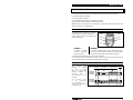
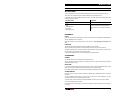
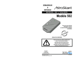
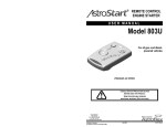
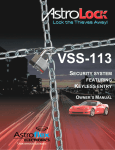
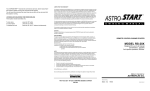
USING YOUR REMOTE CONTROL
Your remote control can transmit on two different
channels, allowing control of two separate vehicles.
?P]XR
;43
Only the “Panic” command is transmitted on both
channels simultaneously.
BcPac
Bc^_
;^RZ
D][^RZ
Cad]Z
CHANNEL 1 :
CHANNEL 2 :
To transmit a command
on channel 1, press desired
button for two seconds.
To transmit a command on channel 2, press desired button, then as
soon as a tone is heard or that the LED flashes once, release the button
for a moment then press it again and hold down for two seconds.
A command will not be executed if you do not press button long enough.
Only one command will be transmitted even if a button is pressed for more than two seconds except for the
“Panic” button, which repeats its command for as long as the button is held down.
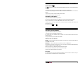
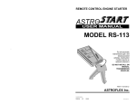
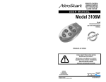
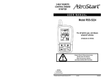
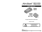
CONFIRMATION
Each
command
being
transmitted
is
confirmed
by
both
an
audible
and a visual signal (LED
indicator),
indicating
the
successive
steps
in
the transmission of the
command.
The
successive
steps
in
the
transmission
and confirmation of a
command are described in
the opposite table.
?aTbbX]V
?aTP\Qd[T
2^]UXa\PcX^]
CaP]b\XbbX^]
2^]UXa\PcX^]
caP]b\XccTS
^]RWP]]T[
2^]UXa\PcX^]
caP]b\XccTS
^]RWP]]T[!
$bTR bTR bTR $bTR
3
<>34;"%
Legend :
Pressing
Preamble
Transmission
Confirmation
Another confirmation is sent by
your remote when you activate
“Panic” mode.
This confirmation indicates whether a button was pressed
by mistake and also confirms button was pressed correctly.
To transmit on channel 2, you must press button again
within half a second for command to be transmitted properly.
This confirmation indicates how long a button must be held down
for a command to be transmitted properly (one second duration).
This confirmation is silent when transmitting on channel 1.
This confirmation indicates when a command is being
sent to the remote starter (one second duration).
This last confirmation indicates that transmission
of command was successfully executed.
1 T T _ ba Xb X] V Ua ^ \ [^ f c^ W XV W
This confirmation is repeated
for as long as button is held
down.
4 XV W cUP bcW XV W _ XR W T S Q T T _ b S d a X] V ca P ] b \ Xb b X^ ]
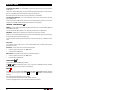
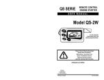
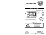
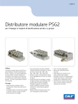
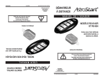
BATTERY REPLACEMENT
We strongly recommend that you keep a replacement set in your
glove compartment.
Your remote is powered by three 3-volt lithium CR-2016 batteries or
equivalent.
To replace the batteries, remove screw on back of remote case,
remove old batteries and replace with new ones.
Make sure that batteries are properly oriented; see illustration
opposite.
4
<>34;"%
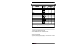
COMMANDS FOR 3006
COMMANDS
BUTTONS
(PICTOGRAM)
PANIC
START / CONTINUOUS MODE
CONFIRMATION
HORN
LIGHTS
SIREN
30 / 60 SEC.
30 / 60 SEC.
30 / 60 SEC.
1♥
1
STOP ♠
1
LOCK / ARM
1
1
UNLOCK / DISARM
2
2
TRUNK
3
4/2/3 ♣
ACTIVATE / DEACTIVATE SENTINEL MODE
ACTIVATE / DEACTIVATE UTILITY # 1
1
ACTIVATE / DEACTIVATE UTILITY # 2
1
RUNTIME ADJUSTMENT
1-4
PRESET TEMPERATURE ADJUSTMENT
1-4
CAR FINDER
7
DISPLAY REMOTE START FAIL CODES
3
1 – 15
♥. THIS CONFIRMATION IS ONLY SENT WHEN COMMAND IS REPEATED WHILE ENGINE IS ALREADY RUNNING.
♣. 4 = ACTIVATED / 2 = DEACTIVATED / 3 = SYSTEM NOT READY.
♠. THIS COMMAND ENDS : RUNTIME, PANIC MODE AND ALARM CONDITION.
CONFIRMATION
In all cases, your Remote Starter will confirm that command has been received properly.
This will be done by either sounding horn or flashing parking lights.
In this manual, confirmation signals are written in an abbreviated form; for example:
(horn: 1, lights: 2)
Means that horn will sound once and parking lights will flash twice.
Parking light confirmations are mandatory.
Horn and siren confirmations are optional (programmable) and require an extra connection and additional
equipment during installation.
Confirmations are explained in more detail under each command.
5
<>34;"%
START COMMANDS
STARTING THE ENGINE
To start the engine, press
button (horn: 0, lights: 1).
The system automatically adjusts ignition duration for your type of vehicle; parking lights flash once (duration: four
seconds) then stay on all the time engine is running.
If more than one command is emitted, each successive start command resets runtime to the beginning, parking
lights flash once to confirm command has been received and horn sounds once to let you know engine is already
running.
Repeating this command will produce an audible confirmation that engine has started, which can be useful if
vehicle is not in sight.
IF ENGINE FAILS TO START
If your system cannot start your engine at first attempt, it will wait for a few seconds and then try again (it could try
again twice depending on reason for failure to start).
After three attempts, it will shut down automatically and wait for new command (see “Start fail Codes“ on page 18).
UPON ENTERING YOUR VEHICLE...
Do not apply brakes; this will stop engine immediately.
Insert ignition key and turn it to “ON” position.
DO NOT TURN IGNITION KEY TO “START” POSITION.
Within 20 seconds, execute Antitheft disarm sequence (if applicable).
See “Antitheft” on page 15.
Drive as usual.
ENGINE RUNTIME
Your engine will stop automatically after a preset time.
Parking lights will stay on as long as engine is running.
Engine runtime is programmable.
WHAT STOPS THE ENGINE
For your safety, engine will not start or will stop if:
Remote control sends a stop message.
Hood is open.
Brakes are applied.
Gearshift is not in “P” or “N”.
Engine is over-revving.
Main switch is OFF.
6
<>34;"%
TRIGGER INPUT
Your remote starter is equipped with a negative trigger (pulse)
input.
This input (enabled during installation) can be connected to
another remote control device or to a timer output.
If this input is connected, consult this device's manual or ask your
technician which command controls the start/stop function.
The start/stop commands received on this input are ignored while
the engine is running on a remote start.
All Start/Stop functions controlled by this input behave in the same
way as functions controlled by remote.
CONTINUOUS MODE
The “Continuous Mode“ function allows to remove the key from the ignition while leaving the engine running.
This convenient feature allows you to leave the vehicle for short periods of time while the climate controls remain
on.
To access the “Continuous Mode“, carry out the “Start“ command while the engine is idling.
See “STARTING THE ENGINE“ on page 6.
Parking lights, engine and preset accessories will remain on for the duration of the programmed runtime
(see “ Setting the runtime ” on page 8).
Remove key, exit vehicle and lock doors. All safety devices will remain active.
IF YOU RETURN TO YOUR VEHICLE BEFORE RUNTIME HAS ELAPSED, JUST TURN THE KEY TO THE
“ON” POSITION AND DEPRESS BRAKE PEDAL.
MAIN SWITCH
Main switch is usually mounted under dashboard.
It is an ON/OFF toggle switch that is used to cancel start functions.
It does not disable other commands which remain active.
STOP
When engine is kept running by Remote Starter, you can stop it with this command (lights: 1, siren: 0).
This command is also used to cancel “Panic” mode and alarm condition.
7
<>34;"%
LOW TEMPERATURE MODE
In Low Temperature (previously called Sentinel) mode, system starts your engine automatically when temperature
falls below a preset level.
Engine will run for programmed runtime, after which system will wait 2½ hours and then start engine again if
temperature is still below preset level.
To activate/deactivate Low Temperature mode, press
and
buttons simultaneously.
When mode is activated:
Parking lights will flash 4 times, then, if temperature is below preset level, engine will start.
If temperature is above preset level, system waits until it goes below preset level before starting.
If system cannot execute command (for example, hood is open), confirmation will be different (lights: 3)(see “Start
Fail Codes“ on page 18).
When mode is deactivated:
Parking lights will flash twice to confirm that mode is deactivated. Applying brakes also deactivates Low
Temperature mode.
START TEMPERATURE ADJUSTMENT
To change preset temperature at which you want your Remote Starter to start engine, press
buttons simultaneously (lights: 1 - 4).
Parking lights will flash from 1 to 4 times to indicate selected start
temperature (see table opposite).
If you send command when ignition has been turned on (by Remote
Starter or key), preset start temperature does not change.
However, confirmation is still sent to indicate last selection.
and
Number of
Flashes
Preset start
temperature
1
-5°C (23°F)
2
-15°C (5°F)
3
-20°C (-7°F)
4
-30°C (-22°F)
Number of
flashes
Runtime
If you send this command while the ignition circuits are activated (by
remote or key), runtime does not change but confirmation is sent to
indicate last selection.
1
2 minutes
2
4 minutes
If Low Temperature mode is already activated when this command is
sent, the command sets or indicates Low Temperature mode runtime.
3
8 minutes
4
18 minutes
SETTING THE RUNTIME
Press buttons
and
simultaneously (parking lights: 1 - 4).
Parking lights flash one to four times to indicate selected runtime (see
table opposite).
1
Note: Runtime is doubled for a diesel engine.
1
A runtime of 2 minutes (4 min. for a diesel engine ) is not recommended for most vehicles unless you intend to
drive off immediately after the remote start. This selection is not available in Low Temperature mode.
8
<>34;"%
SECURITY SYSTEM
SECURITY ZONES
Your security system can use up to six different monitoring devices at the same time to protect your vehicle.
These devices are connected to the control module on different inputs called security zones.
One of these zones can give an audible warning (siren "ON" for 2 seconds) while the other five generate an alarm
condition if the system is armed.
SECURITY ZONES
FUNCTIONS
Warning (pre-shock)
Doors
Hood
Additional sensors
Shock sensor
Ignition (ignition key)
Siren "ON" for 2 seconds
Siren "ON" for a period of 30 seconds to 4
minutes depending on the initial programming
and whether the zone in violation is corrected or
not.
DETERRENTS
ACTIVE
When one of the monitoring devices detects a violation, the system reacts by energizing the following deterrent
devices, depending on which is connected.
The system energize up to four deterrent devices at the same time - siren, parking lights, dome light and/or
horn.
PREVENTIVE
The indicator light indicates the different alarm system conditions (see “Zone codes”).
When it is mounted in a place where it is visible from outside the vehicle, it may also act as a deterrent.
The buzzer (optional) consists of a small piezo-electric element that beeps when the system is armed; this beep
can be heard up to about two meters (six feet) from the vehicle.
It warns possible intruders that your vehicle is equipped with an armed alarm system.
ALARM MODES
WARNING
The warning signal consists in a siren that chirps briefly (two seconds).
When a dual stage shock sensor (optional) is connected to the system, a light shock will activate the warning
signal when the alarm is armed.
PRE-ALARM
If you set off the alarm by mistake and do not want to alarm (or disturb...) the whole neighborhood, the “pre-alarm
mode” cuts in three seconds before the actual alarm to give you time to disarm the system.
In this mode, the parking lights, siren and dome light are activated intermittently for three seconds.
ALARM CONDITION
When the system is in an alarm condition, it energizes its deterrent devices, depending on which is connected to
the module.
The alarm condition remains active for a period of thirty seconds or one minute depending on the initial
programming, after which the system pauses for five seconds.
During this pause, it checks the security zones again and reinitiates the alarm cycle if a zone is still in violation.
This cycle can be repeated up to four times.
If the situation which caused the violation is corrected in the middle of a cycle, the alarm shuts off at the end of the
current cycle.
9
<>34;"%
OPERATION
Your vehicle safety system can function in three different modes, namely manual, semi-automatic and
automatic depending on the initial programming.
Consult the section corresponding to the mode in which your system was configured during installation.
MANUAL
In manual mode, the security system must be armed and disarmed with the remote control.
Consult the table of command on page 5.
The system is armed as soon as the command is received.
If a zone is in violation when the command is received, the alarm will still arm.
However, the zone in violation cannot trigger the alarm since it was not previously in a normal condition.
Manual mode is always available even if your system was configured differently when it was installed.
SEMI-AUTOMATIC
In semi-automatic mode, the security system must be armed and disarmed with the remote control.
Consult the table of command on page 5.
In this mode the system automatically rearms 25 seconds after you have disarmed it if there is no security zone in
violation.
The following table shows how each zone affects the rearming cycle.
Security zone
Hood
Additional sensors
Shock sensor
Ignition
Doors
Warning
Effect on the rearming cycle
These three zones delay the onset of the rearming cycle for as long as they
remain in violation.
These two zones cancel the rearming cycle completely.
No effect
Applying the brake pedal or enabling the “Temporary valet” mode cancel the rearming cycle.
AUTOMATIC
In automatic mode, opening a door initiates the rearming cycle.
The alarm system will be armed thirty seconds after checking that all the security zones are in a normal condition.
This thirty-second period is called the “rearming delay”.
If a zone violation occurs during the rearming delay, the timer will stop counting and start again at thirty seconds
when all the zones have returned to a normal condition.
During the rearming delay, the indicator light flashes rapidly.
After five seconds, the system issues an audible confirmation (1 chirp of the siren) indicating that the system will
arm after 25 seconds.
At the end of this delay, the alarm is armed and issues a second confirmation (1 chirp of the siren and 1 flash of
the parking lights) to indicate that the system is armed correctly.
If you wish to remain inside your vehicle without driving off, you can cancel the rearming cycle by turning the key to
the ignition position (IGN) then back to “OFF” or by depressing the brake pedal.
When you exit the vehicle, the cycle starts again and the system arms automatically.
See also “Temporary valet” mode.
If you disarm the system (to enter the vehicle, for example) and do not open the door within thirty seconds, the
system automatically rearms.
10
<>34;"%
The following table shows how each zone affects the rearming cycle.
Security zone
Hood
Doors
Additional sensor
Shock sensors
Effect on the rearming cycle
These four zones delay the onset of the rearming cycle for as long as they
remain in a violation status.
Turned ON by the ignition switch:
Cancels the rearming cycle
Turned ON by the remote starter module:
No effect
Warning
No effect
Applying the brake pedal or turning the ignition key to the “ON” position cancels the rearming cycle (until a door is
opened, which causes the rearming delay to start over from the beginning of the cycle).
See also “Temporary valet” and “Dome light delay”.
Ignition
Disarming can only be done using the remote control by pressing the
page 5.
button (see the table of command on
The system is immediately disarmed and starts again at the beginning of the rearming delay.
CANCELING ALARM CONDITION
You can cancel the alarm condition by pressing the
the
or the
button, which also disarms the system, or by pressing
button, which cancels the alarm condition without disarming the system.
CONFIRMATION
When you arm or disarm the system, a confirmation is issued by the siren (if it is programmed during installation)
and the parking lights.
When the alarm is armed manually, one confirmation (chirp of the siren and/or flash of the parking lights) means
that all the security zones are in their normal condition and the system is ready.
Three chirps or flashes indicate that one or more zones are in violation (example, a door is open).
When the zone is corrected (example, the door is closed), the system issues another confirmation (one chirp or
flash if all the zones are in their normal condition, three if another zone is in violation).
If a zone is in violation when the system is armed manually and the situation causing the violation is not corrected,
the alarm still arms, but this zone cannot generate an alarm condition.
See also “Dome light delay”.
When you disarm the alarm, two chirps or flashes indicate that no one has tried to break into your vehicle or
otherwise violate the system; four chirps or flashes indicate that an alarm condition occurred during your absence.
The following table summarizes this section.
CONFIRMATION
MEANING
1 blink
System armed with zone in violation.
2 blinks
System disarmed, no violation detected.
3 blinks
System armed with zone in violation. Check the indicator light to know which zone.
System disarmed with violation detected.
Check the indicator light to know what caused the alarm condition.
4 blinks
11
<>34;"%
INDICATOR LIGHT
The indicator light indicates the different alarm system conditions.
When it is mounted in a place where it is visible from outside the vehicle, it may also act as a deterrent.
UPON ARMING - The indicator light displays the codes for the zones in violation (example, a door is open).
Only one code is displayed at a time.
If more than one zone is in violation during arming, the code changes when the zone displayed is corrected
(example, the door is closed).
UPON DISARMING - The indicator light displays the code for the last zone that generated an alarm condition.
The code is displayed when pressing the
pedal is applied.
button and a door is open. The code is repeated until the brake
The following table shows what the zone codes mean (number of flashes).
ZONE CODES
Flash
Zone indication
1
The system is armed.
2
A door is/was open.
3
The hood is/was open.
4
An alarm condition is/was detected on the shock sensor input.
5
The ignition key is/was in the ignition position (IGN).
An alarm condition is/was detected on the additional sensors input (broken window,
movement, etc.).
6
Two other conditions may be shown by the indicator light:
LOW CONSTANT
Indicates that the alarm is disarmed permanently.
RAPID FLASHING
See “Operation (automatic)”.
See “Valet mode”.
SECONDARY FUNCTIONS
ANTI-LOCK
When it is connected to the ignition key cylinder, this function prevents the system from locking the doors during
automatic arming when the key is in the ignition.
It can also be connected to a switch for selecting whether the automatic lock is ACTIVE or INACTIVE.
TEMPORARY VALET MODE
This mode allows you to cancel automatic arming for an indefinite period of time.
You will find it useful when filling up or when working on or around your vehicle.
To enable the Temporary valet mode, press the
flashing rapidly).
button during the 30-second rearming delay (indicator light
When the light stops flashing, it confirms that the Temporary valet mode is enabled.
To cancel this mode, simply turn the ignition key to the “ON ” position.
Opening a door reactivates automatic arming.
You can also arm the system with the remote control, which cancels the Temporary valet mode.
12
<>34;"%
VALET SWITCH
The Valet switch is used to activate the Valet mode or cancel an alarm condition when your Remote control is not
available (lost, weak batteries, etc).
This switch must be located in a hidden location known only to regular users of the vehicle. Ask your installer to
show you where it is located.
VALET MODE
This mode is used to disarm the alarm permanently when your vehicle is in for servicing, for example.
The following sequence will inactivate the alarm system permanently.
Place the key in the ignition and turn it to the IGNITION position (IGN).
Place the VALET switch in the “ON” position.
Remove the ignition key.
To put the alarm back into active mode, repeat the same procedure with the exception of the position of the
VALET switch (this must be put back to the “OFF” position).
When the Valet mode is enabled, the indicator light stays on at half intensity.
REMOTE CONTROL NOT AVAILABLE
This sequence is used to deactivate the alarm when your remote control is out of order.
Enter the vehicle (the alarm will sound).
Place the key in the ignition and turn it to the IGNITION position (IGN).
Place the VALET switch in the “ON” position and then back to the “OFF” position.
Remove the ignition key.
Note: If the system is programmed in automatic mode, it will rearm and you will have to repeat this sequence every
time you use your vehicle.
If you want to avoid this situation, leave the Valet switch in the “ON” position, which will have the effect of enabling
the Valet mode at the same time.
GLOSSARY
SIREN
The siren emits six different sounds, i.e. it chirps repeatedly and alternates between six different sound
sequences.
It is activated intermittently (short repeated chirps) during a pre-alarm and continuously during a warning or alarm
condition.
It can give a confirmation of the ARMING and DISARMING commands with short chirps; see the table in the
CONFIRMATION section.
This function is programmable as ACTIVE or INACTIVE during installation.
HORN
The horn is activated intermittently (short repeated blasts) when there is a warning or alarm condition.
This function is optional and may require additional equipment to be installed.
Consult your installer for more information.
13
<>34;"%
PARKING LIGHTS
The parking lights flash intermittently (repeated flashes) when there is a warning, pre-alarm or alarm condition.
The parking lights also confirm that commands have been received.
See the table in the CONFIRMATION section.
IN VIOLATION
“In violation” means the condition required for a security zone to generate an alarm condition; for example, a door
is open, etc.
DOME LIGHT DELAY
The remote starter can turn on the dome light for 35 seconds when you send an Unlock command (not available in
semi-automatic mode).
In automatic mode, the system ignores the “doors” zone during the dome light delay, which has the effect of
extending the rearming time by 35 seconds.
On certain vehicles, the dome light may remain on after the last door has been closed.
If this option applies to your vehicle, the rearming time is extended by the length of time the dome light is kept on
by the vehicle.
LOCK/UNLOCK COMMANDS
If your vehicle is equipped with electric door locks, several functions can be operated by remote control when
arming or disarming the alarm.
These features are optional and may require purchasing additional equipment.
Consult your dealer for advice.
Following systems can be controlled:
Door locks
Trunk or hatchback release
Interior lights
LOCK
Press
button (lights: 1, siren: 1).
Doors are locked and parking lights flash once to confirm command has been received.
UNLOCK
Press
button (lights: 2, siren: 2). Doors are unlocked and parking lights flash twice to confirm command has
been received.
The “Unlock“ function can be programmed in such a way that the first unlock command only unlocks the driver's
door, while a following unlock command unlocks the other door(s).
Dome light will turn on for 35 seconds every time “Unlock” command is sent.
This 35-second period is cancelled when “Lock” command is sent, brakes are applied or key is inserted in ignition
and turned to “ON” position.
This function is optional and requires an additional connection and equipment during installation.
14
<>34;"%
TRUNK RELEASE
Press
received.
button (lights: 3). Trunk is released and parking lights flash three times to confirm command has been
Trunk cannot be released if alarm is armed (if applicable) or if ignition key is in “ON” position.
In both these cases, parking lights flash once to confirm that command has been received but trunk could not be
released.
If you are not sure you have received confirmation, repeat command.
System will repeat confirmation as often as you wish.
AUTOMATIC LOCK/UNLOCK
Programmable as Active or Inactive during installation.
This function locks doors when ignition key is in “ON” position, engine is running and brakes are applied.
Doors are unlocked when key is turned from “ON” to “OFF” or when Continuous Mode is activated.
If “Unlock“ function is set to unlock only driver's door on the first command, the “Automatic Unlock“ function will
unlock driver's door only.
This function is : Active
Inactive
OTHER COMMANDS
ANTITHEFT (CIRCUIT DISABLER)
Programmable as Active or Inactive during installation.
Your Security System is equipped with an Antitheft system.
This system consists of an output that controls a relay that cuts all circuits required to operate your vehicle
(optional connection).
Two types of Antitheft system are available with Model 3006.
"REMOTE - FREE" TYPE ANTITHEFT
ARMING : This type of Antitheft system arms automatically when ignition key is turned from “ON” to “OFF” and
remains “OFF” for 30 seconds.
DISARMING : To disarm Antitheft system, insert ignition key and turn it to “RUN” position.
One second later, you have 20 seconds to turn one of your vehicle’s accessories (predetermined during
installation) to “ON” position and then to “OFF” position.
Make sure this accessory is in “OFF” position before executing this sequence.
Three seconds later, Antitheft system is disarmed and you can start engine.
LED goes out to confirm that Antitheft system is disarmed.
VALET MODE :
The Valet mode allows you to cancel the antitheft system whenever your vehicle is left to someone to whom you
don't want to disclose your antitheft accessory or disarming sequence.
15
<>34;"%
TO ACCESS VALET MODE, carry out “DISARMING“ sequence then, within 20 seconds, place the Valet switch
to “ON“ position.
If Valet switch is placed in “ON“ position more than 20 seconds following disarming sequence, you will need to turn
ignition key to the “OFF“ position and then repeat the sequence from the beginning.
Note that the antitheft system will not rearm as long as the Valet mode is not deactivated.
TO TURN VALET MODE OFF, carry out the “DISARMING“ sequence then, within 20 seconds, place Valet
switch to “OFF“ position.
If Valet switch is placed in “OFF“ position more than 20 seconds following disarming sequence, you will need to
turn ignition key to the “OFF “ position and then repeat the sequence from the beginning.
“REMOTE” TYPE ANTITHEFT
ARMING : This type of Antitheft system arms automatically when ignition key is turned from “ON” to “OFF” and
remains “OFF” for one minute.
It can also be armed manually by sending a “Lock” command (unless ignition key is in “ON” position).
DISARMING : Antitheft system is disarmed for one minute when you send “Unlock” command.
If ignition key is not turned to “ON” position within one minute, system automatically rearms, thus preventing any
intruder from starting your vehicle, even with ignition key.
It can be connected so that horn sounds if an intruder tries to start your vehicle when it is in ANTITHEFT ACTIVE
mode.
VALET MODE
In this “Antitheft” mode, the Valet function is used to neutralize antitheft system should the remote control be
inoperative for any reason.
ACTIVATING : To access Valet mode, carry out the following sequence.
Place key in ignition switch, then turn it to “RUN“ position.
Place Valet switch to “ON“ position.
DEACTIVATING: To deactivate the Valet mode, carry out the following sequence.
Place key in ignition switch, then turn it to “RUN“ position.
Place Valet switch to “OFF“ position.
CAR FINDER
Programmable as Active or Inactive during installation.
and
buttons simultaneously (lights: 3, horn: 7). This function sounds horn (short tune) and flashes
Press
parking lights to help you locate your vehicle in a large parking lot.
PANIC
Press
button. This command activates parking lights, horn, siren and dome light intermittently, depending
on which is connected to system, for 30 seconds
or 60 seconds
depending on programming during
installation.
Panic mode is used to attract attention if you are in trouble.
This command will not be executed if engine is kept running by ignition key.
In this case, parking lights will flash once to confirm that command has been received.
16
<>34;"%
UTILITY COMMANDS
Programmable as Active or Inactive during installation.
Two additional commands control most of your vehicle’s accessories, depending on which were connected during
installation (headlight, defroster, etc.).
For details, consult your technician.
COMMAND #1
To activate this function, press
and
buttons simultaneously (lights: 1).
The accessory associated with this command ( _____________________________________________ ) is then
, 1 minute
or 8 minutes
, depending on programming.
activated for 1 second
This duration can be cancelled by repeating command (lights: 1).
COMMAND #2
To activate this function, press
and
buttons simultaneously (lights: 1).
The accessory associated with this command ( _____________________________________________ ) is then
, 1 minute
or 8 minutes
, depending on programming.
activated for 1 second
17
<>34;"%
START FAIL CODES
When a remote start attempt fails, it is possible to determine what caused the failure to start.
Press the
and
buttons simultaneously.
The number of times the parking lights flash corresponds to the start fail code.
The table below lists the various start fail codes.
Code
Failure to start details
1
Module has received a Stop command (remote or timer).
2
Brakes have been applied during or after start sequence.
3
Stop command sent by alarm system.
4
Engine does not crank when starting sequence is initiated.
5
Start command ignored because hood is open.
6
Start command ignored because gearshift not in “P” or “N”.
7
Start command ignored because key is in ignition (in “Run” position).
8
Remote starter’s main switch is “OFF”.
9
Run time has elapsed.
10
Remote starter attempted to start engine three times unsuccessfully.
11
Remote starter sensed engine was already running.
12
Engine is over-revving.
13
Engine not cranking fast enough during start sequence.
14
Vehicle draws too much current on remote starter’s auxiliary circuits.
15
Vehicle draws too much current on remote starter’s accessory circuits.
If any of these start fail codes persist, see your dealer.
18
<>34;"%
SAFETY CHECKS
In order to maintain a high safety standard, proceed with following routine checks every month.
HOOD SWITCH
Start your vehicle with Remote Starter.
Open hood.
Engine should stop as soon as hood is opened.
If engine does not stop immediately, turn main switch to “OFF” position and leave it off until situation has been
corrected. Contact your local service center.
DETECTING “P” AND “N” GEARSHIFT POSITIONS
Your starter is designed to check gearshift position at all times.
If key must be in ignition for gearshift to be moved out of “P”, your vehicle is safe as long as keys are kept away
from children.
If, however, gearshift can be put in gear without key being in ignition, proceed with this simple check.
Put gearshift in gear.
Be ready to apply brakes.
Start your vehicle with Remote Starter.
Repeat these steps with gearshift in “Drive” and “Reverse”.
If starter reacts within 90 seconds (which would be abnormal), turn main switch to “OFF” position and leave it off
until situation has been corrected. Contact your local service center.
REPLACING OR BOOSTING VEHICLE BATTERY
If you have to replace or boost your battery for any reason, first turn main switch to “OFF” position and leave it
“OFF” until battery is replaced or fully charged.
Reversing polarity during this operation could
permanently damage your Remote Starter.
19
<>34;"%
LIMITED LIFETIME WARRANTY
ASTROSTART remote starters
Astroflex Inc., the manufacturer of the AstroStart remote starters (“Product”), warrants to the original end-user purchaser that the Product’s
various control modules protected with fuses (“Modules”) shall be free from defects in material and workmanship for as long as the original end
user purchaser continuously owns the automobile the Products was originally installed in and the Product remains continually installed in the
automobile during the warranty period. In accordance with the terms of this limited warranty, Astroflex, at its expense (except as stated below),
shall either repair or replace the Module or part thereof which is proven defective.
Astrostart accessories
Astroflex warrants to the original end-user purchaser that it will repair any AstroStart accessory part installed contemporaneously with the
Product (“Accessory”) which is defective due to workmanship for a period of two (2) years from the date of purchase provided the original enduser purchaser owns the automobile the Accessory was originally installed in and the Accessory remains continually installed in the automobile.
Warranty limitations
-
The warranty period begins on the date the Module or Accessory was purchased. In the event the date of purchase can not be verified,
the manufacturer’s date as indicated by the serial number of the Product or Accessory covered by this warranty shall be the date the
warranty period begins.
-
Installation, repair and service of any covered Module or Accessory must be performed by an authorized Astroflex technician.
Warranty is void if
-
The Product has: (i) a defect or damage due to accident, neglect, fire, misuse, flood, lighting, shipping and handling, or other condition
beyond the control of Astroflex, (ii) has been altered in any way, (iii) has been installed or repaired by anyone other than an authorized
technician, or (iv) has improperly installed or used.
Warranty does not cover
-
Costs of removing the Product or Accessory, sending the defective Product or Accessory to Astroflex, return of the repaired Product or
Accessory and installation of the repaired or replaced Product or Accessory.
-
Batteries.
Owner’s responsibilities
-
Provide a written proof of purchase for the Product/Accessory, showing the date of purchase, installer’s name, and the name of the
purchaser.
-
Send the defective Product/Accessory, postage pre-paid, to Astroflex at the address below and pay the postage costs for the return the
Product/Accessory.
THIS LIMITED WARRANTY IS IN LIEU OF ALL OTHER WARRANTIES, WHETHER ORAL, WRITTEN, EXPRESS OR IMPLIED. THERE
ARE NO WARRANTIES OF MERCHANTABILITY AND FITNESS FOR A PARTICULAR PURPOSE. ASTROFLEX’S WARRANTY
OBLIGATIONS AND PURCHASER’S REMEDIES HEREUNDER ARE SOLELY AND EXCLUSIVELY AS STATED HEREIN. ASTROFLEX’S
LIABILITY, WHETHER BASED ON CONTRACT, TORT, WARRANTY, STRICT LIABILITY, OR ANY OTHER THEORY, SHALL NOT
EXCEED THE PRICE OF THE INDIVIDUAL UNIT WHOSE DEFECT FOR DAMAGE IS THE BASIS OF THE CLAIM. IN NO EVENT SHALL
ASTROFLEX BE LIABLE FOR ANY LOSS OF PROFITS, LOSS OF USE OF FACILITIES OR EQUIPMENT, OR OTHER INCIDENTAL OR
CONSEQUENTIAL DAMAGES.
Some states do not allow the exclusion or limitation of incidental or consequential damages, so the above limitations or exclusions may not
apply to you. Similar exclusions or limitations, including those as to non-assignment, may be applicable in some Canadian Provinces. This
warranty gives you specific legal rights and you may also have other rights which vary from state to state or province to province.
Astroflex Inc.
1164 Route 220
St-Élie d’Orford (Québec)
Canada
J0B 2S0
20