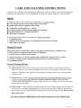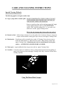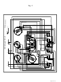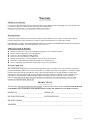
1
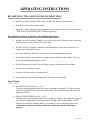
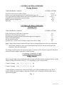
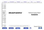
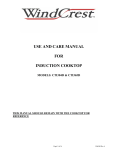
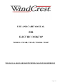
USE AND CARE MANUAL
FOR
ELECTRIC COOKTOP
MODELS: CTE36B, CTE36P, CTE48B & CTE48P
THIS MANUAL SHOULD REMAIN WITH THE COOKTOP FOR REFERENCE
Page# 1 of 1
IMPORTANT SAFETY INSTRUCTIONS
READ ALL INSTRUCTIONS BEFORE USING YOUR COOKTOP
WARNING TO REDUCE THE RISK OF FIRE, ELECTRIC SHOCK, OR INJURY TO
PERSONS, OBSERVE THE FOLLOWING:
1. USE THIS UNIT ONLY IN THE MANNER INTENDED BY THE MANUFACTURER. IF YOU
HAVE ANY QUESTIONS, CONTACT THE MANUFACTURER.
2. BEFORE SERVICING UNIT, SWITCH POWER OFF AT SERVICE PANEL AND LOCK
SERVICE DISCONNECTING MEANS TO PREVENT POWER FROM BEING SWITCHED ON
ACCIDENTALLY. WHEN THE SERVICE DISCONNECTING MEANS CANNOT BE LOCKED,
SECURELY FASTEN A PROMINENT WARNING DEVICE, SUCH AS A TAG, TO THE
SERVICE PANEL.
3. DON NOT COOK ON A COOKTOP HAVING BROKEN OR CRACKED GLASS. CLEANING
SOLUTIONS AND SPILLOVERS MAY PENETRATE THE BROKEN COOKTOP AND
CREATE A RISK IF ELECTRIC SHOCK. TURN OFF ELECTRIC POWER AT THE SERVICE
PANEL AND CALL AN AUTHORIZED SERVICE AGENCY.
WARNING TO REDUCE THE RISK OF INJURY TO PERSONS, IN THE EVENT OF A
COOKTOP GREASE FIRE, OBSERVE THE FOLLOWING:
1. SMOTHER FLAMES with a close fitting lid, cookie sheet, or metal tray, then turn off electric
element. BE CAREFUL TO PREVENT BURNS. If the flames do not go out immediately,
EVACUATE AND CALL THE FIRE DEPARTMENT.
2. NEVER PICK UP A FLAMING PAN. You may be burned.
3. DO NOT USE WATER, including wet dishcloths or towels
a violent steam explosion will result.
4. USE AN EXTINGUISHER ONLY IF:
You know you have a class ABC extinguisher, and you already know how to operate it.
The fire is small and contained in the area where it started.
The fire department is being called.
You can fight the fire with your back to an exit.
WARNING DO NOT STORE ITEMS OF INTEREST TO CHILDREN ABOVE THE
COOKTOP OR AT THE BACK OF IT. IF CHILDREN CLIMB ONTO THE
COOKTOP TO REACH THESE ITEMS, THEY COULD BE SERIOUSLY
INJURED.
1. Do not leave children unattended in area where appliances are in use.
2. Do not allow children to sit or stand on any part of the cooktop.
WARNING DO NOT STORE FLAMMABLE MATERIALS ON OR NEAR THE COOKTOP
AND OBSERVE GOOD SAFETY PRACTICES WHEN USING THE COOKTOP.
Page# 2 of 2
IMPORTANT SAFETY INSTRUCTIONS
1. Wear proper apparel. Loose fitting garments or those with long sleeves should never be worn while
cooking.
2. DO NOT TOUCH HOT COOKING AREA OR THE IMMEDIATE SURROUNDING AREA.
These areas may be hot, even though dark in color. Areas near surface units may become hot enough
to cause burns (among these areas are the cooktop glass, frame or areas facing the cooktop). Never
let clothing, potholders or other flammable materials come in contact with a cooking area until it is
cool.
3. Use dry potholders only. Moist or damp potholders on hot surfaces may cause burns from steam. Do
not use towels or cloths in place of potholders.
4. This appliance is equipped with one or more surface units of different size. Always use utensils that
have flat bottoms and that are large enough to cover the whole cooking (element) area. Using a
utensil smaller than the cooking area will expose a portion of the heated area to direct user contact
and could result in burns and ignition of clothing. Proper relationship of utensil to burner will also
improve efficiency.
5. UTENSIL HANDLES SHOULD BE TURNED INWARD AND NOT EXTEND OVER
ADJACENT SURFACE UNITS. To reduce the risk of burns, ignition of flammable materials, and
spillage due to unintentional contact with the utensil, the handle of the utensil should be positioned
so that it is turned inward, and does not extend over adjacent surface units.
6. Never leave the cooktop unattended when heating elements are turned on. Boil over causes smoking
and greasy spillovers that may ignite.
7. Use high heat setting only when necessary, and never when not monitoring the utensil. Use low to
medium settings to heat oil slowly.
8. Hold the handle of the utensil to prevent movement when stirring or turning food.
9. When using utensils not made of metal, follow the manufacturers directions since they can be
susceptible to breakage when used with high heat settings. Only certain types of glass, ceramic,
glass/ceramic, earthenware, or other glazed cooking utensils are suitable for range-top service
without breaking due to sudden change in temperature.
10. Clean the cooktop with caution. If soil must be removed while the cooktop is hot, clean the hot top
with the metal razor blade scraper only. DO NOT USE WET CLOTH OR SPONGE WHILE THE
COOKTOP IS HOT. Some cleaners may produce noxious fumes id applied to hot surface.
CAUTION The cooktop is for cooking. Never use it to warm or heat a room.
Be sure your cooktop is properly installed and grounded by a qualified service in accordance with
the installation instructions provided with the cooktop.
Do not repair or replace any part of the appliance unless specifically recommended in the use and
care instructions. All other servicing should be done by a qualified service.
Page# 3 of 3
OPERATING INSTRUCTIONS
BEFORE USING THE COOKTOP FOR THE FIRST TIME:
Be sure all packing materials, labels or tape are removed from the cooktop surface.
Wipe with a clean, damp sponge and dry
CARE AND CLEANING INSTRUCTIONS for glass top.)
Precautions to observe to preserve the cooktop appearance.
make it easier to remove food soil and water spots.
The glass surface is resistant to impact but not unbreakable if pan a pan or other object is
dropped on it with sufficient force.
Do not use aluminum foil directly on the glass, it can melt and damage the glass.
Do not allow plastic, paper or cloth to come in contact with the hot glass surface. They can
melt or burn and damage the glass surface.
Do not allow pans to boil dry. This can damage the pan, element and/or the cooktop.
Do not cook food directly on glass.
Do not use the glass surface as cutting board.
Do not slide utensils across cooking surface. This may cause scratching.
Signal Lights
POWER ON LIGHT (See Fig 1 or 2)
The power on light will glow when one or more elements are turned on. The light is located
to the left of the Wind Crest logo on the glass on the CTE48 and is integral with surface hot
light in the CTE36.
SURFACE HOT LIGHT (See Fig 1 or 2)
The light is located to the right of the Wind Crest logo on the glass. The surface hot light will
glow when a cooking surface is too hot to touch. The light will continue to glow, after all
elements are turned off, until the surface(s) is cooled to a safe to touch temperature. Use
caution when working or cleaning around the cooktop if the Surface Hot Light is
glowing.
Page# 4 of 4
OPERATING INSTRUCTIONS
Controls
See Fig 1 of 2 for control locations and operation summary. Each element has a control knob
that is designated for use with it. See Fig 1 or 2 for control knob locations and Fig 3 for
control knob description. Controls are turned on by pushing the knob in and turning the knob in
either direction to the heat setting desired. Caution: The control knobs are designated for
various elements based on the knob graphics. If knobs are removed for cleaning, they
should be replaced in the order removed. See Fig 3 for a description of the knob graphics
and the location of the knob on the cooktop,
The control is in the off position when the OFF graphic on the knob lines up with the red
indicator mark in the bezel, located behind the knob, and snaps into place.
Dual element controls have a detent at LO and HI heat positions, to aid you in locating the
minimum and maximum heat settings. Single elements and warming surface controls have a
detent at HI heat position only. There are a infinite number of settings between LO and HI. The
knob graphics include numbers that aid you in selecting the desired heat setting. The setting
selection is indicated when the knob graphic is aligned with the red indicator mark in the bezel,
located behind the knob. See Fig 4 for heating element recommended settings.
The warming zone control operates in same manner as the controls regulating the heating
elements, but results in much lower heat settings. See Fig 4 for recommended settings.
Practice and experience will ultimately determine the heat settings most appropriate for you. You
may want to make a notation in your cooking references when you determine a setting most
appropriate for a particular food item.
Warming zone guide
Use utensils and pans with flat bases. If plates or platters having a ridge on the bottom are
used do not use a heat setting greater than #4.
Always put food in a utensil, never directly on the cooktop.
Use utensils/pans that are approved or recommended for use on a hot surface.
Accelerate the preheating of the warming surface by setting the control on high for 1 or 2
minutes and then reducing the setting to the desired level.
Do not use a trivet directly on the cooktop.
Keep dishes covered to allow use of lower heat settings, to keep foods hot.
Page# 5 of 5
OPERATING INSTRUCTIONS
Temperature Limiters
All heating elements are equipped with a temperature limiter, for safety reasons. The limiter will cycle
the heating element, regardless of the control setting. This is normal and should not be cause for alarm.
But, the following may cause the cycling to be more frequent.
The bottom of the cooking utensil is not flat, convex or concave.
The utensil/pan is too small in diameter for the element being used.
Material of utensil/pan is poor conductor of heat.
Utensil/pan is empty, ingredients have boiled away.
There is no utensil/pan on the element.
Cookware
The type of cookware used will affect performance.
Flat bottoms utensils/pans with flat bottoms are best. Concave or convex bottoms will cause uneven
and slower heating. If pans are not stable (wobble), before or after heating, they will result in slower and
uneven cooking.
Size the utensil/pan should cover the heating element diameter completely. A slight overhang, up to
Covers
Woks
a cover or lid will reduce cooking times.
use flat bottom wok only. Do not use woks with support rings.
Page# 6 of 6
MODEL CTE48B AND CTE48P
RADIANT ELEMENTS - CONTROLS - SIGNAL LIGHTS
SINGLE
ELEMENT
7"
1800W
BRIDGE
800W
SINGLE
ELEMENT
7"
1800W
SINGLE
ELEMENT
6"
1200W
DUAL
ELEM ENT
8"/5"
2100W/70 0W
SINGLE
ELEMENT
6"
1200W
POWER
ON
SIGNAL
LIGHT
4
2
WARMING
SURFACE
300W
3
DUAL
ELEMENT
9"/6"
2400W /1000W
SURFACE
HOT
SIGNAL
LIGHT
1
1
1
LEFT
LEFT FRONT
RIGHT FRONT
7" ROUND
ELEMENT
CONTROL
PUSH & TURN
IN EITHER
DIRECTION
SINGLE
ELEMENT
CONTROL
PUSH & TURN
IN EITHER
DIRECTION
7" ROUND
ELEMENT
CONTROL
PUSH & TURN
IN EITHER
DIRECTION
4
RIGHT 7" ROUND
& BRIDGE
ELEMENT CONTROL
PUSH & TURN CCW FOR 7" ELEMENT
PUSH & TURN CW FOR 7"
PLUS BRIDGE ELEMENTS
LEFT FRONT DUAL ELEMENT
REAR WARMING
SURFACE
CONTROL
PUSH & TURN
IN EITHER
DIRECTION
RIGHT FRONT DUAL ELEMENT
PUSH & TURN CCW FOR 5" ELEMENT
PUSH & TURN CW FOR 8" PLUS 5" ELEMENTS
PUSH & TURN CCW FOR 6" ELEMENT
PUSH & TURN CW FOR 9" PLUS 6" ELEMENTS
FIG - 1
Page# 7 of 7
MODEL CTE36B AND CTE36P
RADIANT ELEMENTS - CONTROLS - SIGNAL LIGHTS
DUAL
ELEMENT
8"/5"
2100W/700W
SINGLE
ELEMENT
7"
1800W
SINGLE
ELEMENT
6"
1200W
BRIDGE
800W
SINGLE
ELEMENT
7"
1800W
WARMING
SURFACE
300W
DUAL
ELEMENT
9"/6"
2400W/1000W
POWER/SURFACE
HOT
SIGNAL
LIGHT
2
3
4
1
LEFT
7" ROUND
ELEMENT
CONTROL
CENTER REAR
SINGLE
ELEMENT
CONTROL
PUSH & TURN
IN EITHER
DIRECTION
PUSH & TURN
IN EITHER
DIRECTION
RIGHT 7" ROUND
& BRIDGE
ELEMENT CONTROL
PUSH & TURN CCW FOR 7" ELEMENT
PUSH & TURN CW FOR 7"
PLUS BRIDGE ELEMENTS
1
4
REAR WARMING
SURFACE
CONTROL
PUSH & TURN
IN EITHER
DIRECTION
RIGHT FRONT DUAL ELEMENT
PUSH & TURN CCW FOR 6" ELEMENT
PUSH & TURN CW FOR 9" PLUS 6" ELEMENTS
LEFT REAR DUAL ELEMENT
PUSH & TURN CCW FOR 5" ELEMENT
PUSH & TURN CW FOR 8" PLUS 5" ELEMENTS
FIG --22
FIG
Page# 8 of 8
Control Knob Location Instruction
The following describes the graphics for the cooktop knobs when knobs are removed for
cleaning they must be returned to the proper location to ensure the knob graphics
correspond to the element being controlled. See Fig 1 or 2, depending on your cooktop
model, for location of the four (4) knob styles used. The graphics appear on the flange of
the knob.
OFF
HI
OFF
LO
HI
LO
6
1*
6
2
5
2
3*
4
3
4
2
3
5
LO
HI
4
OFF
HI
5
6
OFF
HI
LO
LO
6
2*
6
2
5
2
4*
4
3
4
2
3
5
LO
5
HI
4
6
* Reference knob style location number only does not appear on knob
FIG - 3
Page# 9 of 9
CONTROL SETTING GUIDELINE
Heating Elements
TYPE ITEM BEING COOKED
CONTROL SETTING
Keep food
-1/2
-1/2 to 5
CONTROL SETTING GUIDELINE
Warming Zone
TYPE ITEM BEING COOKED
CONTROL SETTING
4
5 to 6
Quick heat up
Note: A range of heat setting is indicated because the best setting will depend on the type, temperature
and quantity of food as well as type of utensil/pan being used, the element selected and most
important
The settings are also based in 240 volt power supply. If you have a 208 volt power supply the same heat
setting will result in slightly longer time to finish cooking.
CONTROL SETTING GUIDE
Bridge element
When using the bridge element with both single elements and bridge element operating in unison, use the
following settings for reference. See Fig 1 or 2 depending on your cooktop model.
3
4
5
6
HI
Control tolerances/variations may cause the ON/OFF cycle of the individual heaters to vary, this is
normal. Modify the control setting to adjust the ON/OFF cycle of elements so that their glow time is
approximately equal.
Fig 4
Page# 10 of 10
CARE AND CLEANING INSTRUCTIONS
Caring for your cooktop is easy and its beauty will be preserved if you follow a few simple maintenance
techniques described in this section. Additionally some special cleaning methods are also described.
Supplies
The following items will be useful in the maintenance of your glass surface.
Paper towels, sponge or cloth (avoid using soiled wipers)
Razor blade scraper (supplied with cooktop)
Nonmetallic scouring pads (i.e.: Tuffy )
General cleaners (i.e.: Vinegar, Bon Ami )
Mild soap or detergent
The following will be useful in maintaining the stainless steel surface.
Clean damp cloth
Stainless steel cleaner/polish (i.e.: 3M Stainless Steel Cleaner & Polish)
Mild soap or detergent
Cleaners To Avoid
These type cleaners can discolor, scratch, stain, mark or etch the glass or stainless steel.
Glass cleaners containing chlorine bleach or ammonia.
Caustic cleaners, such as oven cleaners.
Abrasive cleaners (i.e.: metal scouring pads, Scotch Brite sponges, S.O.S. pads)
Powder or liquid cleaners containing chlorine bleach or abrasives/cleaners.
Flammable cleaners.
General Cleaning Methods
Glass surface Use a clean soapy sponge, paper towel or cloth to wipe off greasy spatters.
Rinse and wipe dry. Use vinegar if smudges are present. Use a clean paper towel with a small
amount of Cleani
nto the glass surface, let dry and buff with a
clean dry towel.
Stainless steel Caution: Always wipe in the direction of brushed finish grain, side to side, to
avoid cross scratching surface. Do not use abrasive cleaners or pads. Using a mild soap
solution, wipe with clean cloth or sponge. Rinse and dry. Use a stainless steel cleaner on a paper
towel to protect the surface.
Plastic knobs Using a mild soap solution, wipe with a clean cloth or sponge, rinse and dry. To
remove knob for cleaning, grip and pull off. To aid removal, grip with a rubber jar cap removal
pad or insert a piece of paper behind knob and pull knob off. Wipe knob and dry. Do not soak or
put in dishwasher.
CAUTION: UNLESS OTHERWISE NOTED CLEAN SURFACE ONLY WHEN COOL.
Page# 11 of 11
CARE AND CLEANING INSTRUCTIONS
Special Cleaning Methods
The following applies to the glass surface only:
Sugar, syrup, milk or tomato spills
REMOVE IMMEDIATELY/WHILE SURFACE IS HOT
USE RAZOR BLADE SCRAPER ONLY NEVER USE
DRY OR WET TOWELS OR SPONGES.
Remove utensil/pan from surface and turn control off. Angle
scraper slightly and push spill or residue off the heated
5). Let surface cool
This is the only clean up that is done with a hot surface!
Burned on food
Soften using a moist towel over the soil for 20 to 30 minutes. Remove using razor
scraper or non-
Metal marks
marks use mild cleanser (i.e.: Bon Ami ) to remove. Rinse and dry surface and
Aluminum pans can leave metal deposits on the glass
surface ALUMINUM PANS SHOULD BE AVOIDED.
Water spots
Scratches
Cannot be removed. Avoidance is best, by using clean pans and removing spillage of
cooking capability.
Using The Razor Blade Scraper
Page# 12 of 12
N
2
16 BK 20 #58
16 BK 20 #60
H1
16 B K 15 #37
H2
16 BK 15 #38
16 B K 15 #14
H2
P L1 L2
H1
Center Rear
Surface Hot
Power ON
1800
W ATTS
2b
2a
1a 1b
P L1 L2
2a
1a 2b
1b
16 BK 20 #29
16 BK 20 #20
16 BK 20 #19
Right R ear
Warm ing 12 0V
14 BK 15 #16
16 BK 20 #67
16 WH 20 #61
16 WH 20 #24
16 WH 20 #26
2400/1000
W ATTS
16 B K 20 #64
16 B K 20 #63
16 R 20 # 62
16 B K 15 #18
16 BK 15 #36
3
Right Front
5 N N 4
300
WATTS
16 R 20 #57
16 B K 20 #28
2b 1b
2a 1a
14 BK 15 #15
14 R 15 #7
16 R 20 #47
16 BK 20 #44
16 BK 15 #39
2
3
Left Rear
5 N N 4
14 R 15 #6
2
16 B K 20 #43
16 B K 20 #42
16 B K 15 #40
3
Dual Bri dge
Center Front
H1
H2
Dual Bridg e
Left Front
P L1 L2
14 R 15 #4
14 BK 15 #12
14 R 15 #5
16 R 20 #41
14 BK 15 #13
16 R 20 #41
2a
1a 2b
1b
16 BK 20 #52
5 N N 4
1800
W ATTS
16 BK 20 #54
16 BK 20 #31
16 BK 20 #21
8 R 12 #1
800 W ATTS
16 BK 20 #45
16 BK 20 #46
1b
2 b 1a
2a
1200
WATTS
L2
2100/700
WATTS
1a
1b 2a
2b
10 B AR E WIRE SOLID #65
16 BK 20 #50
8 BK 12 #10
16 BK 20 #22
L1
16 B K 20 #32
10 WH 12 #23
16 B K 20 #30
16 BK 20 #66
16 R 20 #41
14 BK 15 #11
NOTE
CONTACTS 1a & 2a - NC
CONTACTS 1b & 2b - NO
16 BK 20 #22A
CTE36B and CTE36P
Fig
5
Page# 13 of 13
16 BK 20 #48
Page# 14 of 14
2
5
N N
14 WH 20 #61
4
16 BK 20 #35
15 BK 15 #15
3
Right Front
14 BK 20 #60
16 WH 15 #24
300
WATTS
16 BK 20 #55
L1 L2
H1
16 BK 15 #36
H2
W arm ing 120V
Right Rear
P
14 R 15 #7
14 R 20 #62
14 BK 20 #63
14 BK 20 #64
1b
2b
1a 2a
16 BK 20 #56
2400/1000
WATTS
1a 2a
1b 2b
14 R 15 #6
14 BK 15 #12
L1
L2
H2
16 BK 15 #37
H1
Center Right
P
14 BK 15 #16
16 BK 20 #34
16 WH 20 #26
14 BK 20 #58
8 R 12 #1
L1
L2
H1
N N
14 BK 15 #11
14 BK 20 #53
L2
H1
H2
Left Rear
P
L1
14 R 15 #5
14 R 15 #2
1a
2a 1b
2b
16 BK 20 #54
14 R 15 #3
16 BK 20 #31
14 BK 15 #13
14 BK 15 #39
3
4
14 BK 15 #10
2
Dual Bridge
Center Rear
5
Pilot Light
(Power On Light)
1a 1b
2a 2b
14 BK 20 #45
1200
WATTS
16 BK 20 #19
14 R 20 #47
14 BK 20 #46
10 BARE WIRE SOLID #65
16 BK 15 #38
H2
Center Left
P
16 BK 20 #33
Surface Hot
16 WH 20 #27
1200
WATTS
2b 2a
1b 1a
14 R 15 #4
16 BK 20 #30
16 BK 20 #29
16 BK 20 #28
L2
14 R 20 #57
8 BK 12 #10
14 BK 20 #44
14 BK 15 #14
L1
2
16 BK 20 #21
16 BK 20 #20
3
4
1b 2b
1a 2a
16 BK 20 #22
N N
1b
1a 2b
2a
1800
WATTS
14 BK 20 #52
Left Front
5
2100/700
WATTS
16 BK 20 #32
1800
WATTS
800 WATTS
14 BK 20 #43
14 BK 20 #59
10 WH 12 #23
16 BK 20 #22A
14 R 20 #41
N
16 BK 15 #40
NOTE:
CONTACTS 1a & 2a - NC
CONTACTS 1b & 2b - NO
14 BK 20 #42
CTE48B and CTE48P
14 R 20 #48
14 BK 20 #50
Warranty
Full One Year Warranty
Covers repairs and replacement of parts found to be defective due to materials and workmanship, for one year from the date
of purchase, or date of occupancy for new previously unoccupied dwelling.
Keep proof of purchase date or occupancy date available for inspection.
Warranty Service
Under terms of this warranty, service must be provided by a factory authorized service agency or representative, during
normal working hours. Labor performed at overtime or premium rates shall not be covered by this warranty.
FOR SERVICE CONTACT YOUR DEALER FOR NAME OF FACTORY AUTHORIZED SERVICER IN YOUR AREA
OR CALL THE FACTORY. FACTORY SERVICE: (877) 387-6721
Items Not Covered In Warranty
Damage or repairs due to service by an unauthorized agency or use of unauthorized parts.
Service visits to teach you how to use the appliance.
Service to correct installation related problems.
Service to reset circuit breakers or replace fuses.
Damage caused by abuse, accident, alteration, misuse or local code violations.
Failure due to other than normal family household use, or commercial use.
Service on products not purchased in country where service is to be performed.
Warranty Application
This warranty applies to appliances used in residential applications only, not commercial use. The warranty is for products
purchased and retained in the 50 states of the USA, District of Columbia, and Canada. If the appliance is sold by the original
purchaser during the warranty period the new owner is protected until expiration of original purchasers warranty. This
warranty gives you specific legal rights. You may also have other rights, which very from state to state. Warrantor is not
responsible for consequential or incidental damage whether arising out of breach of warranty, breach of contract, or
otherwise. Some states do not allow exclusion or limitation of incidental or consequential damages, so the preceding
limitation or exclusion may not apply to you.
PRODUCT DATA
The data plate, showing the model and serial number, is located on the bottom of this unit. Record the model and
and address here for future reference.
MODEL NO. ____________________________ SERIAL NO. _______________________________
DATE OF PURCHASE ____________________ DATE INSTALLED _________________________
ADDRESS __________________________________________________________________________
Page# 15 of 15
CNP Industries, Inc.
P.O. Box 18645
Anaheim, CA 92817
(877) 387-6721 (714) 482-2337 Fax
Page# 16 of 16