1
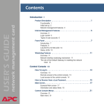
Web/SNMP
Management
SmartSlot Card
AP9606
Installation and
Quick Start Manual
®
Thank You!
Thank you for selecting the American Power Conversion (APC) Web/
SNMP Management SmartSlot Card (AP9606). It has been designed for
many years of reliable, maintenance-free service in combination with
your APC uninterruptible power supply (UPS). APC is dedicated to the
development of high-performance electrical power conversion and control products. We hope that you will find this product a valuable,
convenient addition to your computing system.
Please read this manual! It provides important safety, installation, and
operating instructions that will help you get the most from your Management Card.
Save this manual! It includes instructions for obtaining warranty
service.
Radio frequency interference
Changes or modifications to this unit not expressly approved by the
party responsible for compliance could void the user's authority to operate this equipment.
This equipment has been tested and found to comply with the limits for
a Class A digital device pursuant to part 15 of the FCC Rules. These
limits are designed to provide reasonable protection against harmful
interference when the equipment is operated in a commercial environment. This equipment generates, uses, and can radiate radio frequency
energy and, if not installed and used in accordance with this user manual, may cause harmful interference to radio communications.
Operation of this equipment in a residential area is likely to cause harmful interference. The user will bear sole responsibility for correcting
such interference.
This Class A digital apparatus complies with Canadian ICES-003.
Cet appareil numérique de la classe A est conforme à la norme NMB003 du Canada.
Contents
How to Avoid Equipment Damage . . . . . . . . . . . . . . . . 1
Caution 1
Smart-UPS 1
Matrix-UPS 1
Symmetra Power Array and Silcon DP300E series UPS 1
Expansion or Triple Chassis 1
How to Recover from a Lost Password . . . . . . . . . . . . . 2
Overview 2
Recovery procedure 2
Preliminary Information . . . . . . . . . . . . . . . . . . . . . . . . 3
Features of the Web/SNMP Management Card 3
Related documents 3
Inventory 4
Report damage or missing contents 4
Please recycle 4
UPS Installation . . . . . . . . . . . . . . . . . . . . . . . . . . . . . . 5
Overview 5
Step 1: Install PowerChute plus 5
Step 2: Turn off all power (Smart-UPS or Matrix-UPS) 5
Step 3:Install the Web/SNMP Management Card 6
Expansion/Triple Chassis Installation . . . . . . . . . . . . . . 7
Overview 7
When to Use the AC Adapter (AP9505) Option 7
Step 1: Install PowerChute plus 7
Step 2: Disconnect the chassis from all power 7
Step 3: Install the Web/SNMP Management Card 8
Continued on next page
i
Contents continued
Quick Configuration . . . . . . . . . . . . . . . . . . . . . . . . . . . 9
Overview 9
TCP/IP configuration methods 9
APC Management Card Wizard 10
Local (serial) access 10
Address Resolution Protocol (ARP) and Telnet access 11
Control Console 11
BOOTP 12
How to Access the Web/SNMP Management Card . . . 13
Overview 13
Web interface 13
Telnet 13
SNMP 13
FTP 13
APC Management Card Wizard 13
ii
How to Avoid Equipment Damage
Caution
Smart-UPS
Damage to the UPS or Web/SNMP Management SmartSlot Card
(AP9606) can result if you do not remove all AC and DC power
from a Smart-UPS® or Matrix-UPS® model UPS, SmartSlot
Expansion Chassis (AP9600), or SmartSlot Expansion Triple
Chassis (AP9604, AP9604R or AP9604SR) before you install
the Management Card.
1. Turn off the equipment that connects to the UPS.
2. Disconnect the UPS from its AC input source.
3. Press the OFF button on the UPS for approximately five seconds to turn off the DC (battery) power.
Matrix-UPS
1. Turn off the equipment that connects to the UPS.
2. Turn off the circuit breaker on the rear panel of the UPS.
Symmetra
Power Array and
Silcon DP300E
series UPS
Expansion or
Triple Chassis
You do not need to turn off a Symmetra® Power Array™ or a
Silcon™ DP300E series UPS to install the Management Card.
Make sure that the chassis is disconnected from all power:
Disconnect the chassis cable from the UPS and, if the AC-to-DC
Adapter (AP9505) option is used, disconnect the adapter from
the chassis.
1
How to Recover from a Lost Password
Overview
If the User Name or Password becomes unknown, you can use
a local computer to restore access to a Management Card that
uses the APC AOS module, version 3.0 (or later). The latest
AOS version is available at the APC web site (www.apcc.com).
Recovery
procedure
1. Select a serial port at the computer to be used for a terminalemulation connection with the Management Card.
2. Disable any service that currently uses that serial port, such
as PowerChute plus or UNIX Respond.
3. Connect the smart-signaling cable (940-0024) that came
with the Management Card to a serial port on the computer
and to the serial port on the UPS or chassis.
Note: If the computer uses smart-signaling PowerChute
plus, you do not need to perform step 3: A smartsignaling cable (940-0024 or 940-1524) is already
installed. For simple-signaling, temporarily replace
the PowerChute plus cable.
4. Run a terminal program (such as HyperTerminal).
5. Configure the serial port for 2400 bps, 8 data bits, no parity,
1 stop bit, and no flow control, and save the changes.
6. Press ENTER to display the User Name prompt (you may
need to press ENTER two or three times).
7. Press the reset button on the Management Card.
8. Press ENTER to redisplay the User Name prompt.
9. Use apc for both the User Name and Password to log in.
Note: If you take longer than 30 seconds to log in, you will
need to repeat steps 6 through 8.
10. Select System from the Control Console menu.
11. Select User Manager from the System menu.
12. Select Administrator from the User Manager menu and
follow the on-screen instructions to change the User Name
and Password settings to the new values.
13. Press CTRL-C to exit to the Control Console menu.
14. Log out to save the changes.
15. If necessary, reconnect the simple-signaling PowerChute
plus cable replaced in Step 3.
16. Restart any service disabled in Step 1.
2
Preliminary Information
Features of the
Web/SNMP
Management
Card
The following features have been added to the APC Web/SNMP
Management SmartSlot Card (AP9606):
• Uses the APC PowerChute Network Shutdown utility to
shut down multiple servers
• Provides an event log which is accessible by Telnet, FTP,
or a Web browser
• Generates e-mail notifications for UPS and system events
• Limits SNMP traps and e-mail notifications based on the
severity level of the events
• Supports using simple-signaling PowerChute plus with
the same UPS as the Management Card
• Supports using the APC Management Card Wizard with
Windows® 2000
• Supports the APC Silcon DP300E series UPS models
• Provides UPS-specific application modules:
– sumx*.bin (Smart-UPS/Matrix-UPS)
– sy*.bin (Symmetra Power Array)
– dp3e*.bin (Silcon DP300E series UPS)
Note: The asterisk (*) stands for the version number.
For example, version 3.0.0 of the Symmetra
Power Array application module would have a
file name of sy300.bin.
Related
documents
The APC Web/SNMP Management Card utility CD contains the
following documentation:
• Web/SNMP Management Card User’s Guide
(.\doc\usrguide.pdf)
• Management Card addendum (.\doc\addendum.pdf)
• PowerNet MIB Reference Guide (.\doc\mibguide.pdf)
• Network Management Station (NMS) Reference Guide
(.\doc\nms.pdf)
• CD-ROM contents file (.\content.txt)
• Web/SNMP Management Card Release Notes
(.\relnotes.txt)
• Installation instructions in text format (.\install.txt)
• Troubleshooting documents (.\trouble\*.*)
Continued on next page
3
Preliminary Information, continued
Inventory
In addition to this Installation and Quick Start Guide, the
Management Card package includes the following items:
• Web/SNMP Management SmartSlot Card (AP9606)
• APC Web/SNMP Management Card utility CD
(991-0166)
• Smart-signaling cable (940-0024)
• Installation of Multiple SmartSlot Cards sheet (990-0231)
• Declaration of Conformity (992-0009)
• Warranty registration form
• Web/SNMP Management Card Quality Assurance Test
slip
Note: Save the assurance test slip until you have installed
and configured the Management Card. The slip
contains the MAC address. You may need to refer
to this address when performing the procedures
outlined in this guide’s “Quick Configuration”
section.
Report damage
or missing
contents
Inspect the package and contents for any signs of shipping
damage, and make sure that all parts were sent. If you find
shipping damage, report that damage immediately to the
shipping agent. Also, report any damage, missing contents or
other problems to APC and your APC reseller, immediately.
Please recycle
The shipping materials are recyclable. Please save them for later
use, or dispose of them appropriately.
4
UPS Installation
Overview
The Management Card can be installed in an expansion slot in a
Smart-UPS, Matrix-UPS, or Symmetra Power Array. For a
Silcon DP300E series UPS, the Management Card installs in a
Triple Chassis (either an AP9604R or AP9604SR).
Step 1: Install
PowerChute
If you are installing PowerChute® plus and a Management Card
for the same server, first install PowerChute plus. This allows
you to make sure that PowerChute plus is working properly
before you install the Management Card.
plus
Step 2: Turn off
all power
(Smart-UPS or
Matrix-UPS)
Caution: Damage to the UPS or Management Card can result
if you do not remove all AC and DC power from a
Smart-UPS or Matrix-UPS model UPS. You do not
need to turn power off for a Symmetra Power Array.
Smart-UPS
1. Turn off the equipment that connects to the UPS.
2. Disconnect the UPS from its AC input source.
3. Press the OFF button on the UPS for approximately five seconds to turn off the DC (battery) power.
Matrix-UPS
1. Turn off the equipment that connects to the UPS.
2. Turn off the circuit breaker on the rear panel of the UPS.
Continued on next page
5
UPS Installation, continued
Step 3:Install
the Web/SNMP
Management
Card
Caution: If you are installing the Management Card in a
Symmetra Power Array that uses more than one APC
management peripheral, see the supplied Installation
of Multiple SmartSlot Cards sheet. You must install
the APC peripherals in the correct order, otherwise
the peripherals may fail to operate properly.
1. Use the screws that hold the slot cover in place to secure
the Management Card in the UPS expansion slot.
2. Connect a network interface cable to the 10Base-T network connector on the Management Card.
3. If neccessary, reconnect the PowerChute plus cable.
4. Reconnect the UPS to its input power source.
5. Turn on the UPS.
6. If neccessary, restart the PowerChute plus service.
7. See “Quick Configuration” on page 9.
Link - RX/TX
Reset
Status
10Base-T
Smart Slot
AP9606 Web/SNMP Management Card
Figure 1: Connecting a Management Card in a Smart-UPS
6
Expansion/Triple Chassis Installation
Overview
You must use an SmartSlot Expansion Chassis or a SmartSlot
Expansion Triple Chassis (AP9604, AP9604R or AP9604SR)
under the following circumstances:
• The expansion slot or slots are in use for the Smart-UPS,
Matrix-UPS, or Symmetra Power Array.
• The UPS, such as an older model Matrix-UPS or a Silcon
DP300E series UPS, does not have an expansion slot.
Note: A Silcon DP300E series UPS always uses a Triple
Chassis (AP9604R or AP9604SR).
The Management Card installs in the chassis and communicates
with the UPS through the cable connection between the chassis
and the UPS.
When to Use
the AC Adapter
(AP9505)
Option
You need to use the optional AC Adapter with a chassis under
the following circumstances:
Step 1: Install
PowerChute
If you are installing PowerChute® plus and a Management Card
for the same server, first install PowerChute plus. This allows
you to make sure that PowerChute plus is working properly
before you install the Management Card.
plus
Step 2:
Disconnect the
chassis from all
power
• You want to connect the chassis to an independent AC
input so that the Management Card can continue to
operate if the UPS is turned off or fails.
• The APC management peripherals mounted in a Triple
Chassis may use more current than the UPS can provide
through the UPS-to-chassis cable. The Management Card
uses 110mA. For information about the current used by
other APC management peripherals, see the SmartSlot
Expansion Triple Chassis User’s Guide.
– A Silcon DP300E series UPS provides up to 500 mA.
– A Matrix-UPS, Smart-UPS, or Symmetra Power Array
provides up to 200 mA.
Make sure that the chassis is disconnected from any power
source: Disconnect the chassis cable from the UPS and, if the
AC Adapter (AP9505) option is used, disconnect the adapter
from the chassis.
Continued on next page
7
Expansion/Triple Chassis Installation continued
Step 3: Install
the Web/SNMP
Management
Card
Caution: If the UPS uses more than one APC management
peripheral, see the supplied Installation of Multiple
SmartSlot Cards sheet. You must install the APC
peripherals in the correct order, otherwise the
peripherals may fail to operate properly.
1. If PowerChute plus is installed, stop the PowerChute plus
service and disconnect its cable from the UPS serial port.
2. Use the screws that hold the expansion slot cover in place
to secure the Management Card in the chassis slot.
3. Connect a network interface cable to the Management
Card’s 10Base-T network connector.
4. If you are using the optional AC Adapter (AP9505), do
the following:
a. Connect the adapter to the chassis.
b. Connect the adapter to an independent AC input so that
the Management Card can continue to operate if the
UPS is turned off or fails.
5. If neccessary, reconnect the PowerChute plus cable.
6. If neccessary, restart the PowerChute plus service.
7. See “Quick Configuration” on page 9.
Figure 2: Installing a Management Card in a SmartSlot Expansion
Chassis (AP9600)
8
Quick Configuration
Overview
You must configure three TCP/IP settings before the
Management Card can operate on a network:
• The IP address of the Management Card
• The subnet mask
• The Default Gateway
Note: If a Default Gateway is unavailable, use the IP
address of a computer located on the same subnet
as the Management Card that is usually running.
The Management Card uses the Default Gateway
to test the network when traffic is very light. See
“Watchdog Features” in the “Introduction” of the
Web/SNMP Management Card User’s Guide
(.\doc\usrguide.pdf) for more information about
the watchdog role of the Default Gateway.
TCP/IP
configuration
methods
If you have access to a computer that uses Windows 95,
Windows 98, Windows 2000, or Windows NT 4.0, see “APC
Management Card Wizard” on page 10 for information about
how to use the Wizard to configure one or more Management
Cards.
If you cannot use the APC Management Card Wizard, use the
following information to configure your Management Card:
• To use the Control Console feature from a computer that
connects to the serial port on the UPS or chassis, see
“Local (serial) access” on page 10.
• To use the Control Console feature from a computer that
is on the same subnet as the Management Card. See
“Address Resolution Protocol (ARP) and Telnet access”
on page 11.
• To use an RFC951-compliant BOOTP server to configure
one or more Management Cards on your network, see
“BOOTP” on page 12.
Continued on next page
9
Quick Configuration continued
APC
Management
Card Wizard
To use the APC Management Card Wizard to configure a
Management Card from a computer that uses Windows 95,
Windows 98, Windows NT 4.0, or Windows 2000, perform the
following steps.
Note: To use the Wizard to configure multiple Management
Cards, to download firmware, or to configure a
Management Card from a configuration file, see the
Management Card Addendum (.\doc\addendum.pdf).
1. Follow the on-screen instructions to install the Wizard
from the APC Web/SNMP Management Card utility CD.
2. Launch the Wizard, when prompted, or, if prompted to
restart the computer, access the Wizard from the Start
menu once the computer restarts.
3. Wait for the Wizard to discover the unconfigured Management Card, then follow the on-screen instructions to
define the TCP/IP settings.
Note: If you leave the Start a Web browser when
finished option enabled, you can use apc for both
the User Name and Password to access the
Management Card through your browser.
Local (serial)
access
You can use a computer that connects to the Management Card
through the serial port at the UPS or chassis to access the
Control Console.
1. Select a serial port at the computer to be used for a terminal-emulation connection with the Management Card.
2. Disable any service that currently uses that serial port,
such as PowerChute plus or UNIX Respond.
3. Connect the smart-signaling cable (940-0024) that came
with the Management Card to a serial port on the computer and to the serial port on the UPS or chassis.
Note: If the computer uses smart-signaling PowerChute
plus, you do not need to perform step 3: A smartsignaling cable (940-0024 or 940-1524) is already
installed. For simple-signaling, temporarily replace
the PowerChute plus cable.
Continued on next page
10
Quick Configuration continued
Local (serial)
access,
continued
4. Run a terminal program, such as HyperTerminal.
5. Configure the serial port for 2400 bps, 8 data bits, no parity, 1 stop bit, and no flow control, and save the changes.
6. Press ENTER to display the User Name prompt (you may
need to press ENTER two or three times).
7. Use apc for the User Name and for the Password.
8. See “Control Console” below to finish the configuration.
Address
Resolution
Protocol (ARP)
and Telnet
access
You can use ARP and Telnet to access the Control Console from
a computer on the same subnet as the Management Card.
1. Use ARP to assign an IP address to a Management Card
that has a specified MAC address. For example, to assign
IP address 159.215.15.141 to a Management Card that
has a MAC address of 00 c0 b7 63 9f 67, the ARP command would be:
arp -s 159.215.15.141 00-c0-b7-63-9f-67
Note: The Web/SNMP Management Card Quality
Assurance slip lists the MAC address.
2. Use Telnet to access the Management Card at its now
defined IP address. For the IP address assigned by ARP in
the previous step, the Telnet command would be:
telnet 159.215.15.141
3. Use apc for the User Name and for the Password.
4. See “Control Console” below to finish the configuration.
Control Console
Once you log into the Control Console, as described in either
“Local (serial) access” on page 10 or “Address Resolution
Protocol (ARP) and Telnet access” above, do the following:
1. Choose Network from the Control Console menu.
2. Choose TCP/IP from the Network menu.
3. Disable BOOTP, if enabled, and select Accept Changes.
4. Set the System IP, Subnet Mask and Default Gateway
address values and select Accept Changes.
5. Press CTRL-C to exit to the Control Console menu.
6. Click Log out to have the changes take effect.
Continued on next page
11
Quick Configuration continued
Control
Console,
continued
7. If you disconnected a PowerChute plus cable for local
access to the Control Console, reconnect that cable.
8. If you disabled any service for local access to the Control
Console, restart that service.
Note: If PowerChute plus does not reestablish
communications with the UPS, see “How to
Correct a Communication Lost Problem” in the
“Troubleshooting” section of the Web/SNMP
Management Card User’s Guide
(.\doc\usrguide.pdf).
BOOTP
You can use an RFC951-compliant BOOTP server to configure
the TCP/IP settings the Management Card needs.
1. Enter the Management Card’s MAC and IP addresses, the
Subnet Mask and Default Gateway settings, and an
optional Bootup File Name in the BOOTPTAB file of the
BOOTP server.
Note: See the Web/SNMP Management Card Quality
Assurance slip for the MAC address; see Step 2 for
more information about using a Bootup file.
2. When the Management Card reboots, the BOOTP server
provides it with the TCP/IP settings.
– If you specified a Bootup File Name, the Management
Card will attempt to transfer that file from a TFTP or
FTP server residing on the BOOTP server. The
Management Card will assume all settings specified in
the bootup file.
– If you did not specify a Bootup File Name, the
Management Card can be configured remotely by using
Telnet or by using Web interface: User Name and
Password are both apc, by default.
Note: You must use the APC Management Card
Wizard or the APC initialization (*.ini) text fileto-binary configuration (*.cfg) file conversion
utility, i2c300, to create the Bootup file. See
“APC Management Card Wizard” on page 10 to
install the Wizard. For detailed information
about how to create a Bootup file, see the
BOOTP section in the Management Card
Addendum (.\doc\addendum.pdf).
12
How to Access the Web/SNMP Management Card
Overview
Once the Management Card is running on your network, you can
use several different interfaces to access the Management Card.
Note: For more information about how to use the interfaces
identified here, see the Web/SNMP Management Card
User’s Guide (.\doc\usrguide.pdf) and the Management
Card Addendum (.\doc\addendum.pdf).
Web interface
You can use Internet Explorer (3.01 or later) or Netscape®
Navigator (3.0 or later) to configure Management Card options,
or to view the Event log.
1. Address the Management Card by its IP address or DNS
name (if configured).
2. Enter the User Name and Password (apc by default).
Telnet
You can use Telnet to view the event log or to configure
Management Card options.
1. At a command prompt, type telnet address and
press ENTER, where address is the Management Card’s
IP address or DNS name (if configured).
2. Enter the User Name and Password (apc by default).
SNMP
After you add the PowerNet MIB to a standard SNMP MIB
browser, you can use that browser for SNMP access to a
Management Card. The default read community name is public;
the default read/write community name is private.
FTP
You can use FTP (enabled by default) to download new
firmware or to access a copy of the event log.
1. At a command prompt, type ftp address
and press ENTER, where address is the Management
Card’s IP address.
2. Enter the User Name and Password (apc by default).
APC
Management
Card Wizard
You can use the APC Management Card Wizard to download
new firmware and to reconfigure multiple Management Cards
over the network.
13
Notes
14
w w w. a p c c . c o m
Toll-free Customer Support: Online Customer Support:
U.S. & Canada
1-800-800-4272
U.S. & Canada http://www.apcc.com/support
Address:
American Power Conversion Corporation
132 Fairgrounds Road
P. O. Box 278
West Kingston, Rhode Island 02892
USA
Entire contents copyright © 2000 by American Power Conversion. All rights reserved.
APC, Smart-UPS, Matrix-UPS, Symmetra, Power Array, Silcon, and PowerChute are all trademarks
or registered trademarks of APC. All other trademarks, product names, and corporate names
are the property of their respective owners and are used for informational purposes only.
990-6008C
6/2000