1
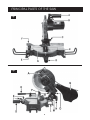
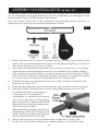
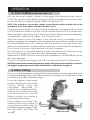
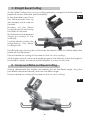
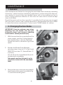
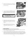
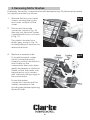
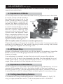
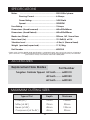
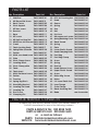
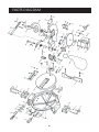
COMPOUND MITRE SAW
Model CMS251
OPERATION & MAINTENANCE
©
INSTRUCTIONS
0801
© Copyright Clarke International. All rights reserved, August 2001
2
Thank you for purchasing this CLARKE 10 inch Compound Mitre Saw. This extremely
versatile machine is designed for DIY/Hobby use and for use by tradesmen in a
light industrial environment
Before operating the machine, please read this leaflet thoroughly and carefully follow all
instructions. This will ensure the safety of yourself and that of others around you, and you
can also look forward to the machine giving you long and satisfactory service.
GUARANTEE
This CLARKE product is guaranteed against faulty manufacture for a period of 12
months from the date of purchase. Please keep your receipt as proof of purchase.
This guarantee is invalid if the product is found to have been abused or tampered
with in any way, or not used for the purpose for which it was intended.
Faulty goods should be returned to their place of purchase, no product can be
returned to us without prior permission.
This guarantee does not effect your statutory rights.
CONTENTS
Page
Safety Precautions ......................................................................... 4
Additional precautions for Table/Mitre Saws .............................. 6
Electrical Connections .................................................................. 7
Principal Parts ................................................................................. 8
Features ........................................................................................... 9
Assembly and Installation ........................................................... 10
Operation ...................................................................................... 11
Cross Cutting ................................................................... 11
Mitre Cutting ................................................................... 11
Bevel Cutting ................................................................... 12
Compound (Bevel/Mitre) Cutting ................................. 12
Maintenance ................................................................................ 13
Blade renewal ................................................................. 13
Motor Brush Renewal ..................................................... 15
Adjustments .................................................................................. 16
Specifications ............................................................................... 17
Accessories ................................................................................... 17
Maximum Cutting Sizes ............................................................... 17
Parts and Service Contacts ......................................................... 18
Parts List ......................................................................................... 18
Parts Diagram ............................................................................... 19
3
GENERAL SAFETY RULES FOR OPERATING MACHINERY
WARNING:
As with all machinery, there are certain hazards involved with their
operation and use. Exercising respect and caution will considerably
lessen the risk of personal injury. However, if normal safety precautions
are overlooked or ignored, personal injury to the operator or damage to
property, may result.
1. READ and BECOME FAMILIAR with the entire operating manual. Learn
the machines’ applications and limitations as well as the specific
potential hazards peculiar to it.
2. EARTH ALL MACHINES. If the machine is equipped with three-pin plug,
it should be plugged into a three-pin electrical socket. Never remove
the earth pin.
3. ALWAYS ensure that ADEQUATE LIGHTING is available. A minimum
intensity of 300 lux should be provided. Ensure that lighting is placed
so that you will not be working in your own shadow.
4. CHECK for DAMAGE before using the machine. Any damaged part,
such as a guard etc., should be checked to ensure that it will operate
properly, and perform its intended function. Check for alignment of
moving parts, breakage of parts, mountings, and any other condition
that may affect the machines’ operation. Any damage should be
properly repaired or the part replaced. If in doubt, DO NOT USE the
machine. Consult your local dealer.
5. DISCONNECT the MACHINE from the power supply before servicing
and when changing accessories such as blades, etc.
6. ALWAYS KEEP GUARDS IN PLACE and in working order.
7. ALWAYS WEAR SAFETY GOGGLES, manufactured to the latest European
Safety Standards. Also use a face or dust mask if the cutting operation
is dusty. Everyday eyeglasses do not have impact resistant lenses,
they are NOT safety glasses.
8. KEEP WORK AREA CLEAN. Cluttered areas and benches invite
accidents.
9. ALWAYS WEAR EAR PROTECTORS/DEFENDERS.
10. DON’T FORCE THE MACHINE. It will do a better and safer job at the rate
for which it was designed.
4
11. REMOVE ADJUSTING KEYS AND WRENCHES. Form the habit of checking
to see that keys and adjusting wrenches are removed from the
machine before switching on.
12. Do not operate machine while under the influence of DRUGS,
ALCOHOL OR ANY MEDICATION.
13. USE ONLY RECOMMENDED ACCESSORIES. The use of improper
accessories could be hazardous.
14. NEVER LEAVE MACHINE RUNNING UNATTENDED. Turn power OFF. Do
not leave machine until it comes to a complete stop.
15. ALWAYS DISCONNECT FROM THE MAINS SUPPLY when adjusting,
changing parts, or working on machine.
16. AVOID DANGEROUS ENVIRONMENT. Don’t use power machines in
damp or wet locations or expose them to rain. Keep your work area
well illuminated. DO NOT USE in explosive atmosphere (around paint,
flammable liquids etc.).
17. KEEP CHILDREN AWAY. All visitors should be kept a safe distance from
the work area, especially whilst operating the unit.
19. MAINTAIN MACHINE IN TOP CONDITION. Keep tools sharp and clean
for the best and safest performance. Follow maintenance instructions.
21. DON’T OVERREACH. Keep your proper footing and balance at all times.
For best footing, wear rubber soled footwear. Keep floor clear of oil,
scrap wood, etc.
22. WEAR PROPER APPAREL. Loose clothing or jewellery may get caught
in moving parts. Wear protective hair covering to contain long hair.
23. MAKE WORKSHOP CHILDPROOF. Cover the saw adequately when not
in use, to prevent children from damaging themselves by tampering
with it.
24. NEVER STAND ON THE MACHINE. Serious injury could occur if the
machine is tipped or if a cutting tool is accidentally contacted. Do
not store materials above or near a machine, such that it is necessary
to stand on the machine to reach them.
25. HANDLE WITH EXTREME CARE whenever transporting or installing
machinery, and always use a lifting tool.
26. AVOID ACCIDENTAL STARTING. Ensure the switch is OFF before plugging
in to mains.
27. ALWAYS CONCENTRATE ON THE JOB IN HAND, no matter how trivial it
may seem. Accidents are frequently caused by carelessness due to
familiarity.
5
ADDITIONAL SAFETY INSTRUCTIONS for MITRE SAWS
1. Wear safety goggles as protection against flying wood chips and saw
dust. In many cases, a full face shield is even better protection. A dust
mask is also recommended to keep saw dust out of your lungs.
2. Use a solid wood workbench which will not move under load.
3. This saw is designed for use by DIY/Hobbyists, or tradesmen in a light
commercial environment ONLY.
4. Clear the work table of all objects except the workpiece (tools, scraps,
rulers etc.) before switching on the saw.
5. Keep your fingers well away from the blade.
6. Switch off the saw, and make sure the blade has come to a complete
stop before clearing sawdust or off-cuts from the table.
7. Make sure there are no nails or foreign objects in the part of the
workpiece to be sawn.
8. Set up the machine and make all adjustments with the power OFF,
and disconnected from the supply.
9. DO NOT operate the machine with the guards removed. They must all
be in place and securely fastened when performing any operation
10. Use ONLY approved replacement saw blades. Contact your local
CLARKE dealer for advice. The use of inferior blades may increase the
risk of injury.
11. DO NOT saw any material that does not have a flat surface on which
to bear.
12. Do Not force the blade, lower it gently into the work.
13. Ensure you have complete control of the Cutting Head at all times.
When a cut is completed, return it to its uppermost position gently.
DO NOT allow it to snap back heavily under spring pressure.
14. Always clamp the work to the table...DO NOT perform freehand
operations.
15. Ensure that the portion of the workpiece being cut bears firmly against
the back fence.
16. Provide adequate support for long workpieces.
17. Never use solvents for cleaning plastic parts as this could cause
damage to the material. A soft damp cloth only is required.
6
ELECTRICAL CONNECTIONS
Connect the mains lead to a standard, 230 Volt (50Hz) electrical supply
through an approved 13 amp BS 1363 plug, or a suitably fused isolator
switch.
WARNING! THIS APPLIANCE IS DOUBLE INSULATED
IMPORTANT: The wires in the mains lead are coloured in accordance with
the following code:
Blue
-
Neutral
Brown
-
Live
As the colours of the flexible lead of this appliance may not correspond
with the coloured markings identifying terminals in your plug proceed as
follows:
Connect BROWN cord to terminal marked with “L” or coloured RED.
Connect BLUE cord to the terminal marked with “N” or coloured BLACK.
If this appliance is fitted with a plug which is moulded onto the electric
cable (i.e. non-rewirable) please note:
1. The plug must be thrown away if it is cut from the electric cable. There
is a danger of electric shock if it is subsequently inserted into a socket
outlet.
2. Never use the plug without the fuse cover fitted.
3. Should you wish to replace a detachable fuse carrier, ensure that the
correct replacement is used (as indicated by marking or colour code).
4. Replacement fuse covers can be obtained from your local dealer or
most electrical stockists.
Fuse Rating
The fuse in the plug must be replaced with one of the same rating -13amps
and this replacement must be ASTA approved to BS1362.
Cable Extension
If a cable extension is needed, it is essential to ensure that the size of the
conductors is at least the same size as those of the power cable supplied.
7
PRINCIPAL PARTS OF THE SAW
Fig.1
Fig.2
8
LEGEND
A Cutting Head Release Lever
J
Table Release Lever
B
K
Pointer
C Cutting Head Locking Pin
L
Stabiliser
D Table Locking Knob
M Bevel Scale
E
Work Clamp
N Bevel Locking Knob
F
Back Fence
O Head Return Spring Tension Adjuster
Trigger Switch (ON/OFF)
G Table Insert
P
H Front Mounting Hole
Q Dust Bag
Cutting Head Stop Screw
FEATURES (Ref. Figs. 1 and 2)
As its’ name implies, the machine is a Bevel/Mitre Saw, capable of straight cross
cutting, and cutting bevels and mitres, or a combination of the two.
The main arm, or Cutting Head, carries the motor and the tungsten carbide saw
blade. It is allowed to swivel to produce mitre cuts and tilt to the left to produce
bevel cuts.
The maximum sizes of wood that may be cut in any of these processes is given on
page 17.
A dust extraction port is provided at the rear of the machine to which the dust
bag (Q), is attached. If required, a vacuum extraction device may be used which
will provide fast and efficient removal of sawdust. The extraction device may be
used continuously or intermittently depending upon your requirements.
The Cutting Head is locked in its lower position for transit purposes. To release it,
pull out the Head Locking Pin, (C). It may be necessary to apply slight downward
pressure to the head in order to do so, and allow the head to rise to its upper
position gently, under control.
The head will lock in its upper position, and is prevented from being lowered until
the Head Release Lever (A) is moved sideways.
9
ASSEMBLY and INSTALLATION. Re: Figs 1 & 2
On receipt inspect the machine to ensure that all parts are accounted for and
that no damage was incurred during transit. Any deficiency or damage should
be reported to your CLARKE dealer immediately.
The main body of the saw is fully assembled and adjusted at the factory. It is
necessary only to fit the accessories supplied as follows:
Fig.3
1.
2.
3.
4.
5.
6.
7.
Mount the machine on a firm solid base that will not move under load. Ensure
there is an appropriate electrical supply, and adequate lighting, so that you
will not be working in your own shadow.
Four holes are provided in the base, one of which is shown at H, so that the
machine may be bolted permanently to a workbench for added stability.
Alternatively it may be bolted to a piece of plywood with a thickness of 5/8”
minimum. If this method is preferred, the plywood support should be clamped
to a solid base or workbench whenever the saw is being used.
The Work Clamp may be slipped into one of the sockets provided for the
purpose, as shown at ‘E’.
Slide the Work Supports into their mountings, one on either side of the base.
Screw the Table Locking Knob into the Locking Mechanism as shown at D.
To move the table, first ensure the
Locking Knob is slackened off
completely, i.e. turned anticlockwise
one or two turns, then, whilst grasping
the Locking Knob, depress the Table
Release Lever, and keep depressed
whilst turning the table.
Release the Locking Lever and Knob at
the desired position, as indicated on the
Fig.4
scale, and lock in position by screwing
the Locking Knob IN until it is firm.
Attach the dust bag to the dust extraction outlet with its spring clip.
Finally, pull out the rear stabiliser for added stability, if mounted loosely.
10
OPERATION.
A. Cross Cutting (at 90O) Ref: Figs 1 & 2
First, set the work in place. Clamp it firmly against the table and back fence.
Check the security of the Bevel Locking Knob (N) and tighten if necessary, also
ensure the table is locked using the Table Locking Knob (D).
NOTE: If the workpiece is not entirely straight, ensure that the portion at either side of the
intended cut rests firmly against the table and back fence.
It is important to ensure that one end of the workpiece is completely free to move
i.e. NOT clamped or held in any way. This will normally be the off-cut or shorter end.
When satisfied, make a final check to ensure that all safety precautions are being
complied with, then pull the Trigger - B, to start the motor.
Allow the blade to reach full speed. If any unusual sounds or vibrations occur,
release the trigger immediately and investigate the cause. When satisfied, move
the Head Release Lever (A), sideways with the thumb of your right hand, and
gently lower the head so that the blade comes into contact with the workpiece.
Do not force the blade, a light pressure is all that is required.
You will notice that to provide maximum safety, the blade is not exposed at any
time, and the guard rises automatically as the blade is lowered.
Nevertheless, NEVER treat the machine with indifference, and NEVER be casual
with your approach.
To switch off, release the Trigger whilst still maintaining full control of the head.
NOTE: The Head should rise under spring pressure, gently. If the movement is too rapid or conversely,
too sluggish, spring tension needs to be adjusted. Refer to ‘Adjustments’ on page 16.
B. Mitre Cutting
This is a cross cutting operation, except that the saw blade is set at an angle to the work,
but remains perpendicular to the table. The head is mounted on the table which is free
to rotate by up to 45O, to the left and right.
Fig.5
To set the required mitre angle,
rotate the table (and hence the
Cutting Head) using the
procedure
described
on
page10, to the desired position,
lining up the angle on the scale,
with the pointer (K). Lock the
Table in position by screwing in
the Locking Knob firmly.
The procedure for cutting is the
same as that for cross cutting. For
convenience, positive stops are
provided at various angles. These
are: Zero (90O), 15O, 22.5O, 30O
and 45O
Mitre Cut at 45O
11
C. Straight Bevel Cutting
As with Mitre Cutting, this is a cross cutting operation, except that the blade is not
perpendicular to the table (see illustration)
Fig.6
Ensure the table is set so that
the table pointer lines up
with the zero on the scale on
the bed.
Slacken off the Bevel
Locking Knob (N), and swing
the Head to the side.
Set the head to the required
angle according to the
scale (M).
Lock the head in position by
retightening the Bevel
Locking Knob.
The 45O adjuster is factory set so that when the Head is tilted to its fullest extent the
blade will cut 45O bevel.
The procedure for cutting is the same as that for cross cutting.
If the angle is critical, use a small angle gauge on the table to check the angle of
the blade to table. Assistance will be required to carry out this task.
D. Compound Mitre and Bevel Cutting.
Having determined the angles you require, first set the Bevel angle, using the
procedure described above, and then the Mitre angle.
The procedure for cutting is the same as that for cross cutting.
Fig.7
12
MAINTENANCE
1. General
User maintenance is limited to changing the saw blade when necessary, renewing
the motors’ carbon brushes, maintaining adjustments, and ensuring that after use,
any sawdust or wood chips are cleaned away, with a low pressure air line or
brush, paying particular attention to the motor air vents which should be kept
clear at all times.
Should the motor not function normally, it is possible that it has become clogged
with saw dust, in which case, it will be necessary to disassemble the motor in order
to clean the various components. Contact your CLARKE dealer for advice.
2. Changing the Saw Blade
IMPORTANT: Exercise extreme care when
handling the saw blade. The tips are
extremely sharp, and careless handling
could result in severe personal injury.
1.
With the machine disconnected from the
mains supply, and the Cutting Head in
the raised position, remove the Blade
Guard Arm Link Pin, arrowed in Fig. 8, and
retain.
2.
Slacken the Blade Guard Bracket
securing screw, shown at ‘A’ in Fig. 9, and
REMOVE the screw ‘B’. (Leave Screw ‘A’
in place.)
Fig.8
Fig.9
This will allow the Lower Blade Guard to
be removed completely.
Take great care from this point, not to
come into contact with the saw blade
teeth.
Fig.10
3.
Remove the two screws securing the left
hand lower plastic guard, arrowed in Fig.
10, and remove the guard.
13
Fig.11
4.
Remove the screw securing the upper
plastic guard, arrowed in Fig.11, and pull
away the guard.
5.
Unscrew and remove the Blade securing
screw using the claw and box spanners
provided, taking great care to avoid
damaging your hand on the saw blade
teeth.
Fig.12
IMPORTANT: The securing screw has
a LEFT HAND THREAD, i.e. turn it
CLOCKWISE to undo.
Fig.13
6.
Remove the outer flange followed by
the blade. If necessary give the blade a
gentle tap to dislodge it from the inner
flange.
7.
Reassemble in reverse order, ensuring
the tips of the blade point downwards
at the front, as shown in Fig. 13.
Hints and Tips.
1.
When replacing the upper plastic blade guard (para 4 above), take care
not to overtighten the securing screw.
2.
To replace the Lower Blade Guard Bracket (para.2 above), centralise the
guard about the blade, then position the bracket so that screw ‘A’ engages
with the slotted hole in the bracket. Tighten screw (A). Using the screw as a
pivot move the bracket until the other screw hole, in the Upper Blade Guard,
and the hole in the bracket are aligned. Enter the screw and tighten.
14
3. Renewing Motor Brushes
Eventually, the motors’ carbon brushes will need replacing. This task may be carried
out quickly and easily as follows.
1.
Remove the two cross head
screws, securing the motors’
end cover, and pull off the
cover.
2.
Disconnect the spade
connector, shown in Fig. 15,
then pull out the brush carrier,
complete with brush, as shown
in Fig. 14.
Fig.14
The cable is located on a
plastic peg, shown in Fig. 15
and will simply pull away as you
remove the brush.
4.
Replace in reverse order.
Fig.15
To locate the brush carrier,
(which houses the brush),
correctly, position the brush so
that it bears on the
commutator then push down
gently and evenly on the brush
carrier so that the carrier can
be pushed on to its runners,
with the brush sitting snugly on
the commutator.
Ensure the spade
connector is secure and the
cable is mounted on the
locating peg before replacing
the end cover.
15
ADJUSTMENTS
Ref: Fig 16
It may be necessary from time to time, to check various settings and make
appropriate adjustments.
a. Squareness of Blade
It is most important to check that the blade is exactly perpendicular to the table.
To do this, place a small square on
Fig.16
the table and bring it up to the
blade, checking to see if it is square.
If an adjustment is required, first
slacken the Bevel Locking Knob,
then slacken off the adjuster locknut
T, screw the adjuster (S) in or out, as
the case may be until the blade is
exactly square, keeping light
pressure on the head to keep it in
contact with the adjuster screw.
When completely satisfied, lock the
adjuster with the lock nut, and with
the head resting against the stop,
tighten the Bevel Locking Knob.
NOTE: It simplifies matters if assistance is used during this process.
Check the position of the pointer in relation to the scale. If necessary zero the
pointer by slackening off the pointer securing screw, moving the pointer
accordingly and retighten the securing screw.
b. 45O Bevel Stop
Slacken off the Bevel Locking Knob, and tilt the Head to its maximum. Lower the
Blade and with a small 45O gauge between the bed and blade, check for
trueness of angle.
If an adjustment is required, slacken the locknut which secures the adjuster
shown at U in Fig.16. and is found beneath the table. Turn the adjuster in or out
as the case may be, using an appropriate Hex. wrench, to acquire the correct
angle. When satisfied, lock the adjuster with the locknut.
c. Squareness of Backfence
Place a square flat on the table with its base resting on the Backfence. If it is not
square with the edge of the slot in the table, slacken off the two backfence
securing screws R, Fig.2, using an appropriate Hex. wrench, sufficient to be able
to move the fence until it is square. When satisfied, tighten the securing screws.
d. Cutting Head Spring Tension
To increase the Cutting Head spring tension, screw the adjuster (O, Fig.2), ‘IN’
using an appropriate Hex. wrench, until the required tension is achieved.
16
SPECIFICATIONS
Motor:
................................................................... 230V 50Hz 1phase.
Running Current ........................................ 6.5Amps
Power Rating: ............................................ 1400 Watts
Speed: ....................................................... 3900RPM
Fuse Rating .............................................................. 13Amps
Dimensions: (Head Lowered) ................................ 445x490x365mm
Dimensions: (Head Raised) ................................... 445x490x520mm
Blade size (Fitted): .................................................. 250mm, 36T, 16mm Bore
Noise level (Lw) ....................................................... 101.9dB(A) at 1M
Vibration Level ........................................................ <2.5m/s² (Normal Load)
Weight (packed/unpacked) ............................... 17.2/15kg
Part Number ............................................................ 6500768
Please note that the details and specifications contained herein, are correct at the time of going to
print. However, CLARKE International reserve the right to change specifications at any time without
prior notice. Always consult the machine’s data plate
ACCESSORIES
Replacement Saw Blades
Part Number
Tungsten Carbide Tipped 24 Tooth ........ 6490110
40 Tooth ........ 6490120
60 Tooth ........ 6490130
MAXIMUM CUTTING SIZES
Type of Cut
Depth
Thickness
Cross (90°)
70mm
120mm
Mitre (at 45°)
70mm
90mm
Bevel (at 45°)
40mm
120mm
Compound (at 2x 45°)
40mm
90mm
17
PARTS LIST
No. Desciption
Parts List
1
Stabiliser
TMCCMS25101
2
5
M6 Round Hd Screw
Back Fence
TMCCMS2512
TMCCMS25105
6
7
10
11
12
13
15
16
17
20
21
24
25
26
27
28
29
30
31
32
33
34
35
36
37
38
39
Work Support
TMCCMS25106
M5 hex screw
TMCCMS25107
Bracket
TMCCMS25110
Base
TMCCMS25111
M5 screw
TMCCMS25112
M8 Self Locking Nut TMCCMS25113
M8x25 hex skt hd screw TMCCMS25115
Crank
TMCCMS25116
Table Locking Knob TMCCMS2517
Spring Plate w/handle TMCCMS25120
Pointer
TMCCMS25121
M4x8 cross head screw TMCCMS25124
Plate
TMCCMS25125
Work Clamp Screw
TMCCMS25126
Locating Block
TMCCMS25127
Work Clamp plate
TMCCMS25128
Table
TMCCMS25129
Table insert
TMCCMS25130
M4x8 flat head screw TMCCMS25131
Pointer
TMCCMS25132
Trunnion
TMCCMS25133
Spring Brg Block
TMCCMS25134
Head Mtg Bracket
TMCCMS25135
Locating Pin Head
TMCCMS25136
Locating Pin
TMCCMS25137
Dust Cover
TMCCMS25138
Clamping Pin
TMCCMS25139
No. Desciption
40
41
42
43
44
45
46
47
48
49
50
51
52
55
56
57
58
59
60
61
63
64
67
68
69
70
71
72
80
M16 Self Locking Nut
Head
Sleeve
Spring
Arm
Bolt
Link Arm
M6 square-neck screw
Spring Retaining Cover
Blade Guard
Spring
Plate
Lower Plastic Guard
Head Clamping Knob
Dust Bag
Dust Bag Clamp
Screw
Spring
Bracket
Head Release Lever
Upper Plastic Guard
Screw
Motor Mtg. Screw
Motor
L.H. Lower Plastic Gd.
Inner Flange
Outer Flange
Blade Securing Nut
Blade
Parts List
TMCCMS25140
TMCCMS25141
TMCCMS25142
TMCCMS25143
TMCCMS25144
TMCCMS25145
TMCCMS25146
TMCCMS25147
TMCCMS25148
TMCCMS25149
TMCCMS25150
TMCCMS25151
TMCCMS25152
TMCCMS25155
TMCCMS25156
TMCCMS25157
TMCCMS25158
TMCCMS25159
TMCCMS25160
TMCCMS25161
TMCCMS25163
TMCCMS25164
TMCCMS25167
TMCCMS25168
TMCCMS25169
TMCCMS25170
TMCCMS25171
TMCCMS25172
see Accessories
PARTS & SERVICE CONTACTS
For Spare Parts and Service, please contact your nearest dealer, or
CLARKE International, on one of the following numbers.
PARTS & SERVICE TEL: 020 8988 7400
PARTS & SERVICE FAX: 020 8558 3622
or e-mail as follows:
PARTS: [email protected]
SERVICE: [email protected]
18
PARTS DIAGRAM
19