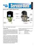
Download BENDIX BA-922 COMPRESSOR Troubleshooting guide
Transcript
The Air Brake Handbook
©2004 Bendix Commercial Vehicle Systems LLC • All Rights Reserved
The Air Brake Handbook
©2004 Bendix Commercial Vehicle Systems LLC • All Rights Reserved
www.bendix.com
1-800-AIR-BRAKE (1-800-247-2725)
1
Device Index
Device Index
F
A
™
A-18 Controller Assy. . . . . . . . . . .
Actuators . . . . . . . . . . . . . . . . . . . . .
AD-2™ Air Dryer . . . . . . . . . . . . . . .
AD-4™ Air Dryer . . . . . . . . . . . . . . .
AD-9™ Air Dryer . . . . . . . . . . . . . . .
AD-IP™ Air Dryer . . . . . . . . . . . . . .
AD-IS™ Air Dryer Module . . . . . . . .
AD-SP™ Air Dryer . . . . . . . . . . . . . .
AF-3™ In-line Air Filter . . . . . . . . . .
Air Disc Brakes . . . . . . . . . . . . . . . .
ASA-5™ Automatic Slack Adjuster .
42
17
12
12
12
12
12
13
13
20
18
B
BA-922™ Air Compressor . . . . . . . . . . 8
BA-921™ Air Compressor . . . . . . . 8, 9
BA-922™ Air Compressor . . . . . . . . . . 9
BASIC™ Test Kit . . . . . . . . . . . . . . . . . . 9
Bendix Modules . . . . . . . . . . . . . . . . 45
BP-1™ Brake Proportioning Valve . . 22
BP-R1™ Bobtail Proportioning
Relay Valve . . . . . . . . . . . . . . . . . . . . 22
BVA-85™ Brake Valve Actuator . . . . 46
BX-2150™ Air Compressor . . . . . . . . . 8
C
Converter Dolly Brakes . . . . . . . . . 33
Cyclone DuraDrain™ Trailer
Water Separator . . . . . . . . . . . . . . . 13
D
D-2™ Governor . . . . . . . . . . . . . . . . 10
DC-4™ Double Check Valve . . . . . . 14
DD3® Safety Actuator . . . . . . . . . . . 17
Dryer Reservoir Module . . . . . . . . . 12
DS-2™ Double Check and Stop
Light Switch . . . . . . . . . . . . . . . . . . . 14
DuraFlo™ 596 Air Compressor . . . 8, 9
E
E-10™ Brake Valve . . . . . . . . . . . . . .
E-10P™ Brake Valve . . . . . . . . . . . . .
E-10PR™ Brake Valve . . . . . . . . . . . .
E-10PR™ Retarder Control
Brake Valve . . . . . . . . . . . . . . . . . . . .
E-12™, E-15™ Brake Valves . . . . . . . .
E-14™ Brake Valve . . . . . . . . . . . . . .
E-6™ Brake Valve . . . . . . . . . . . . . . .
E-7™ Brake Valve . . . . . . . . . . . . . . .
E-8P™ Brake Valve . . . . . . . . . . . . . .
EC-30™ ABS/ATC Controller . . . . .
EC-60™ ABS/ATC Controller . . . . .
ESP® Functionality . . . . . . . . . . . . . .
ET-S™ and ET-S2™ Electronic
Throttle/Treadles . . . . . . . . . . . . . . .
EverFlow™ Module . . . . . . . . . . . . . .
2
15
15
15
16
15
15
15
15
15
36
36
39
46
13
S
™
FD-3 Fan Clutch . . . . . . . . . . . . . . 46
FD-l™ Fan Clutch . . . . . . . . . . . . . . . 46
M-32™ and M-32QR™ Modulators . 35
MC-30™ Controller Assy. . . . . . . . . 42
MV-3™ Dash Control Module . . . . . 29
S-Cam Brakes . . . . . . . . . . . . . . . . . .
SB-1™ Spring Brake Actuator . . . . .
SC-3™Single Check Valve . . . . . . . . .
SC-PR™ Valve . . . . . . . . . . . . . . . . . .
SD-3™ Roto Safety Actuator . . . . . .
SL-4™ and SL-5™ Stop Lamp
Switches . . . . . . . . . . . . . . . . . . . . . .
Spring Brake Actuators . . . . . . . . . .
SR-2™ Spring Brake Valve . . . . . . . . .
SR-4™ Spring Brake Valve . . . . . . . . .
SR-5™ Spring Brake Valve . . . . . . . . .
ST-1™, ST- 3™ and ST-4™
Safety Valves . . . . . . . . . . . . . . . . . . .
SureStroke™ Indicator . . . . . . . . . . .
SV-1™ Synchro Valve . . . . . . . . . . 27,
SV-4™ Trailer Release Valve . . . . . . .
System-Guard® Trailer Air Dryer . .
P
T
I
Inlet Check Valve . . . . . . . . . . . . . . . 10
Inlet Regulating Valve . . . . . . . . . . . . 10
L
LP-2™ and LP-3™ Low Pressure
Indicators . . . . . . . . . . . . . . . . . . . . .
LQ-4™ Ratio Valve . . . . . . . . . . . . . .
LQ-4™ Ratio Valve . . . . . . . . . . . . . .
LQ-4™ Valve . . . . . . . . . . . . . . . . . . .
LQ-5™ Bobtail Ratio Valve . . . . . . . .
11
21
21
21
22
M
PE-4™ Control Valve . . . . . . . . . . . . .
PP-1™ and PP-2™ Valves . . . . . . . . . .
PP-1™ Control Valve . . . . . . . . . . . . .
PP-3™ Control Valve . . . . . . . . . . . . .
PP-5™ Push-Pull Control Valve . . . .
PP-7™ Control Valve . . . . . . . . . . . . .
PP-8™ Control Valve . . . . . . . . . . . . .
PP-DC™ Park Control Valve . . . . . .
PR-3™ Reservoir Control Valve . . . .
PR-4™ Pressure Protection Valve . .
PuraGuard® QC™ Oil
Coalescing Filter . . . . . . . . . . . . . . .
32
24
34
24
27
24
24
28
34
14
13
Q
QR-1™ Quick Release Valve . . . . . .
QR-1C™ Quick Release Valve . . . . .
QR-L™ Inline Quick Release Valve .
QRN-2™ Quick Release Valve . . . . .
QRV™ Quick Release Valve . . . . . . .
21
26
21
21
21
19
17
11
13
17
26
17
31
31
31
10
18
34
34
13
TC-2™ Trailer Control Valve . . . . . . 29
TC-6™ Trailer Control Valve . . . . . . 29
TE-1™ Trailer Emergency Stop Light 32
TP-3™ Tractor Protection Valve . . . . 30
TP-3DC™ Tractor Protection Valve . 30
TP-4™ Tractor Protection Valve . . . . 30
TP-5™ Tractor Protection Valve . . . . 30
TR-2™ Valve . . . . . . . . . . . . . . . . . . . 27
TR-3™ Valve . . . . . . . . . . . . . . . . . . . 27
TR-5™ Lock Line Control Valve . . . . 32
Trailer Control (TC) Valves . . . . . . . 29
Tu-Flo® 550 Air Compressor . . . . . 8, 9
Tu-Flo® 750 Air Compressor . . . . . 8, 9
TW-1™, TW-3™ and TW-6™
Control Valves . . . . . . . . . . . . . . . . . 26
TW-11™ Valve . . . . . . . . . . . . . . . . . . 26
V
Vision Systems . . . . . . . . . . . . . . . . . 45
W
R
R-12DC™ Relay Valve . . . . . . . . . . . .
R-12P™ Relay Valve . . . . . . . . . . . 23,
R-12™ Relay Valve . . . . . . . . . . . . . . .
R-14™ Relay Valve . . . . . . . . . . . . . . .
R-6™ Relay Valve . . . . . . . . . . . . . . . .
R-7™ Modulating Valve . . . . . . . . . . .
R-8P™ Relay Valve . . . . . . . . . . . . . . .
R-8™ Relay Valve . . . . . . . . . . . . . . . .
RD-3™ Control Valve . . . . . . . . . . . .
RDU™ (Remote Diagnostic Unit) . .
RE-6NC™ Relay Emergency Valve . .
Reservoirs . . . . . . . . . . . . . . . . . . . .
RV-1™ Pressure Reducing Valve . . . .
23
34
23
23
23
23
23
23
27
44
34
11
14
WS-24™ Wheel Speed Sensors . . . . 35
Y
Yaw Stability . . . . . . . . . . . . . . . . . . . 39
www.bendix.com
1-800-AIR-BRAKE (1-800-247-2725)
Handbook Section Index
How to use the Air Brake Handbook
This nine-section handbook provides an introduction to the use and
operation of Bendix air brake systems and devices.
Components are introduced and shown with typical system diagrams
to show where they are used. As new components are introduced and
their function explained, they gradually build up to a complete
functioning air brake system.
Partial system-drawings, throughout the manual, assist in explaining of
the use of the components. See the front inside cover for an example
of a tractor system schematic in color.
Device Index . . . . . . . . . . . . . . . . . . . . . . . . . . . . . . 2
Air Brake System General Precautions . . . . . . . . . 4
General Precautions . . . . . . . . . . . . . . . . . . . . . . . . 4
Section One: A One-Page Introduction to
Air Brake Systems . . . . . . . . . . . . . . . . . . . . . 5
Section Two: The Charging System . . . . 6-14
Overview . . . . . . . . . . . . . . . . . . . . . . . . . . . . . . . . . 6
Compressors . . . . . . . . . . . . . . . . . . . . . . . . . . . . . 7-8
Compressor Maintenance Guidelines . . . . . . . . . . . 9
Governors and Components . . . . . . . . . . . . . . . . 10
Reservoirs and Components . . . . . . . . . . . . . . . . 11
Air Dryers . . . . . . . . . . . . . . . . . . . . . . . . . . . . . . . 12
Air Dryers and Filters . . . . . . . . . . . . . . . . . . . . . . 13
Miscellaneous Charging System Related
Components . . . . . . . . . . . . . . . . . . . . . . . . . . . . . 14
Section Three: The Control System . . . . 17-32
Dual Circuit Brake Valves . . . . . . . . . . . . . . . . . 15-16
Actuators . . . . . . . . . . . . . . . . . . . . . . . . . . . . . . . . 17
Slack Adjusters . . . . . . . . . . . . . . . . . . . . . . . . . . . . 18
Foundation Brakes . . . . . . . . . . . . . . . . . . . . . . . 19-20
Quick Release, Ratio Valves . . . . . . . . . . . . . . . . . . 21
Ratio, Proportioning Valves . . . . . . . . . . . . . . . . . . 22
Relay Valves . . . . . . . . . . . . . . . . . . . . . . . . . . . . . . . 23
Push-Pull Valves . . . . . . . . . . . . . . . . . . . . . . . . . . . 24
Spring Brake Valves . . . . . . . . . . . . . . . . . . . . . . . . 25
Lever Operated Control Valves . . . . . . . . . . . . . . 26
Miscellaneous Control Valves . . . . . . . . . . . . . . . . 27
Section Four: Tractor/Trailer Parking
and Emergency Systems . . . . . . . . . . . . . 28-32
Systems . . . . . . . . . . . . . . . . . . . . . . . . . . . . . . . . 28-29
Dash Control Modules . . . . . . . . . . . . . . . . . . . . . 29
Tractor Protection Valves . . . . . . . . . . . . . . . . . . . 30
Trailer Spring Brake Valves . . . . . . . . . . . . . . . . . 31-32
Section Five: Trailers/Converter
Dolly Brakes . . . . . . . . . . . . . . . . . . . . . . .33-34
www.bendix.com
1-800-AIR-BRAKE (1-800-247-2725)
Section Six:
Antilock Braking Systems (ABS) . . . . 35 - 48
ABS Components,Truck and
Tractor ABS Operation . . . . . . . . . . . . . . . . . . . 35-36
Truck and Tractor ABS Operation, ATC . . . . . . . 37
Straight Truck Sample Schematic . . . . . . . . . . . . . 38
Advanced ABS . . . . . . . . . . . . . . . . . . . . . . . . . . . . 39
Advanced ABS Operation . . . . . . . . . . . . . . . . . . 40
Advanced ABS Features . . . . . . . . . . . . . . . . . . . 40-41
Trailer ABS Components and Operation . . . . . . . 42
Trailer ABS Operation and Features,
PLC . . . . . . . . . . . . . . . . . . . . . . . . . . . . . . . . . . . . . 43
Troubleshooting ABS . . . . . . . . . . . . . . . . . . . . . 43-44
Section Seven: Miscellaneous commercial
vehicle products from Bendix . . . . . . . . .45-46
Section Eight:
Air Brake System Fundamentals . . . . . . . . 47
Braking Force . . . . . . . . . . . . . . . . . . . . . . . . . . . . . 48
Leverage . . . . . . . . . . . . . . . . . . . . . . . . . . . . . . . 49-50
Deceleration . . . . . . . . . . . . . . . . . . . . . . . . . . . 50-51
Compressed Air . . . . . . . . . . . . . . . . . . . . . . . . . 51-53
Compressed Air Brakes . . . . . . . . . . . . . . . . . . . . . 54
S-Cam and Air Disc Brakes . . . . . . . . . . . . . . . . . . 55
Air Brake System Balance: Pneumatic Systems . . 56
Air Brake System Balance: Mechanical Systems . 57
Section Nine: Air Brake System
Troubleshooting Tests . . . . . . . . . . . . . . . 58-60
Bendix Videos and Literature . . . . . . . . . . . . . . 61-62
List of Service Data Sheets . . . . . . . . . . . . . . . . . . 63
Sample Schematic . . . . . . . . . . . . . . inside front cover
DIN symbols are used in this handbook.
3
General Precautions
IMPORTANT
The systems presented in this manual are intended for illustrative
purposes only and are not intended to be used for actual vehicle piping.
Air Brake System General Precautions
WARNING! PLEASE READ AND FOLLOW THESE
INSTRUCTIONS TO AVOID PERSONAL INJURY
OR DEATH:
When working on or around a vehicle, the following general
precautions should be observed at all times.
1. Park the vehicle on a level surface, apply the
parking brakes, and always block the wheels.
Always wear safety glasses.
2. Stop the engine and remove ignition key when
working under or around the vehicle. When
working in the engine compartment, the engine
should be shut off and the ignition key should
be removed.Where circumstances require that
the engine be in operation, EXTREME
CAUTION should be used to prevent personal
injury resulting from contact with moving,
rotating, leaking, heated or electrically charged
components.
3. Do not attempt to install, remove, disassemble
or assemble a component until you have read
and thoroughly understand the recommended
procedures. Use only the proper tools and
observe all precautions pertaining to use of
those tools.
4. If the work is being performed on the vehicle’s
air brake system, or any auxiliary pressurized
air systems, make certain to drain the air
pressure from all reservoirs before beginning
ANY work on the vehicle. If the vehicle is
equipped with an AD-IS™ air dryer system or
a dryer reservoir module, be sure to drain the
purge reservoir.
5. Following the vehicle manufacturer’s
recommended procedures, deactivate the
electrical system in a manner that safely
removes all electrical power from the vehicle.
4
6. Never exceed manufacturer’s recommended
pressures.
7. Never connect or disconnect a hose or line
containing pressure; it may whip. Never remove
a component or plug unless you are certain all
system pressure has been depleted.
8. Use only genuine Bendix® replacement parts,
components and kits. Replacement hardware,
tubing, hose, fittings, etc. must be of equivalent
size, type and strength as original equipment
and be designed specifically for such
applications and systems.
9. Components with stripped threads or damaged
parts should be replaced rather than repaired.
Do not attempt repairs requiring machining or
welding unless specifically stated and approved
by the vehicle and component manufacturer.
10. Prior to returning the vehicle to service, make
certain all components and systems are
restored to their proper operating condition.
11. For vehicles with Antilock Traction Control
(ATC), the ATC function must be disabled (ATC
indicator lamp should be ON) prior to
performing any vehicle maintenance where one
or more wheels on a drive axle are lifted off
the ground and moving.
www.bendix.com
1-800-AIR-BRAKE (1-800-247-2725)
Introduction
Section 1: One-Page Introduction
Air Supply
The vehicle’s compressor takes in filtered air, either at
atmospheric pressure from the outside (or already at
an increased pressure, from the engine turbocharger
in some cases), and compresses it. The compressed
air is delivered to the air dryer where water and a small
amount of oil is removed. The air then travels into the
air reservoirs (“air tanks”) - typically delivered to a
rear brake system reservoir and a front brake system
reservoir as well as any attached trailer reservoirs. For
each system, the air pressurizes the reservoir and the
air hoses all the way to the next control valve, where
the air pressure remains, ready to be used.
A vehicle may use compressed air for many tasks. Some
examples are: to provide force for braking, to deliver
air to a particular component, to off-load bulk goods,
etc.
Normal Braking
When the driver applies the foot brake, a plunger within
the foot brake valve moves, opening channels within
the valve that allow the air pressure waiting there to
pass through and be delivered to the rear and front
brake systems. The pressure quickly increases in the
brake chambers and applies force to the push rod,
transferring the force to the S-Cam or air disc brake.
(See page 22 for more about foundation brakes.)
Frictional forces slow the wheels and the vehicle comes
to a stop. When the brakes are released, the air in the
brake chambers is able to be quickly released and enable
the driver to drive away.
Vehicle Parking
Vehicles are parked using powerful springs which are
part of the spring brake assembly, to engage the brakes
and hold the vehicle in position. When the driver
prepares to move away and releases the parking brake,
the spring force is countered by the introduction of air
pressure. Anti-compounding valve features in the
system design help prevent the application of both the
spring and service brakes together.
Antilock Braking Systems (ABS)
Most commercial vehicles use electronic Antilock
Braking System (ABS) to help improve braking when
excessive wheel slip, or wheel lock-up, is detected.
Bendix® Electronic Control Units (ECUs) use patented
technology to monitor wheel speeds (on all wheels
equipped with speed sensors) and use ABS modulator
valves to adjust or pulse the braking force being applied
and released, many times per second, during an ABS
event. ABS typically improves stability and steerability,
and also reduces stopping distances on most surfaces.
In addition to the ABS features above, some recent
model ECUs have a drag torque control feature which
reduces driven-axle wheel slip (due to driveline inertia)
by communicating with the engine’s controller and
increasing the engine torque.
Antilock Traction Control
In addition to the ABS function, some Bendix ECU
models provide an Automatic Traction Control (ATC)
feature which can help improve vehicle stability and
traction during vehicle acceleration (at low speeds),
and lateral stability while driving through curves.
Electronic Stability Program (ESP®*)
Recent Bendix® ABS advances include ESP® which has
the ability to apply brakes to individual wheel ends, and
the trailer, to counteract the trailer “push” during
maneuvers that may lead to loss of control or jackknifes
on low to high friction surfaces (snow, rain, asphalt,
concrete, etc.)
Roll Stability Program (RSP)
The Bendix Roll Stability Program (RSP), is an all-axle
ABS solution that helps reduce vehicle speed by applying
all vehicle brakes as needed, reducing the tendency to
roll over. RSP focuses on reducing the vehicle’s speed
below the critical roll threshold during directionchanging maneuvers such as exit ramps and obstacle
avoidance on dry, high friction surfaces.
Emergency Braking
In emergency situations where system air pressure is
reduced or lost, government regulations require
vehicles to meet specified stopping distances. As an
example, some straight truck system designs use
modulated parking-brake applications to bring the
vehicle to a stop.
Vision Systems
Bendix offers video camera systems that help drivers
back vehicles up safely, assist drivers with viewing what
is in their blind spots around their vehicles, as well as
infrared XVision® night vision camera systems that
provide drivers advanced warning of obstacles in their
pathway at night by seeing 3 to 5 times further than
their standard headlights. All of our camera systems
can be purchased individually to meet drivers’ specific
needs or can be purchased as a total system to provide
a complete 360 degree 24/7 video camera system for
drivers.
*ESP is a registered trademark of Daimler Chrysler.
www.bendix.com
1-800-AIR-BRAKE (1-800-247-2725)
5
Overview
Section 2: The Charging System
The charging system consists of:
• An air compressor
• A governor, to control when the compressor
needs to build, or stop building, air for the system
and also to control the air dryer purge cycle
• An air dryer, to remove water and oil droplets
from the air
• Reservoirs (or “air tanks”) to store air to be used
for vehicle braking, etc.
•
Safety valves to protect against excessive pressure
in the system in the event that a charging system
component malfunction occurs, e.g. a line blockage
Single check valves to maintain a one-way flow
of air into the reservoirs. This arrangement protects
the contents from being drained in the event of an
upstream loss of pressure
Low pressure indicators to alert the driver
whenever a reservoir has less than a pre-set amount
of air available
•
•
Secondary
Reservoir
Low Pressure Indicator
Check Valve
Safety
Valve
Air Dryer
Check Valve
Governor
Purge
Valve
Air Compressor
Drain Valve
Primary
Reservoir
Safety Valve
Supply
Reservoir
Note: Although a typical
three-reservoir system is
shown here, some system
designs do not use a
Supply reservoir.
Bendix Air Compressors
The air compressor is the source of energy for the air
brake system.
Usually driven by the vehicle engine, the air compressor
builds the air pressure for the air brake system. The air
compressor is typically cooled by the engine coolant
system and lubricated by the engine oil supply. (Certain
models have self-lubricated and/or air-cooled versions
available.) Note: Air compressor shafts can rotate in
either direction.
The vehicle’s compressor draws in filtered air, either
at atmospheric pressure from the outside (or already
at an increased pressure, from the engine turbocharger
where permitted), and compresses it.
6
The brake system needs a supply of compressed air
between a preset maximum and minimum. The
governor (along with a synchro valve for the Bendix®
DuraFlo ™ 596 air compressor) monitors the air
pressure in the supply reservoir and controls when
the compressor needs to pump air into the air system
(also known as the “air build cycle” - the compressor
is “running loaded”) and when the compressor should
simply turn over without building pressure (“running
unloaded”). When the air pressure becomes greater
than that of the preset “cut-out”, the governor controls
the unloader mechanism of the compressor to stop
the compressor from building air and also causes the
air dryer to purge. As the service reservoir air pressure
www.bendix.com
1-800-AIR-BRAKE (1-800-247-2725)
Compressors
drops to the “cut-in” setting of the governor, the
governor returns the compressor back to building air
and the air dryer to air drying mode.
As the atmospheric air is compressed, all the water
vapor originally in the air is carried along into the air
system, as well as a small amount of the compressor
lubricating oil as vapor.
The duty cycle is the ratio of time the compressor
spends building air to the total engine running time.
Air compressors are designed to build air (run “loaded”)
up to 25% of the time. Higher duty cycles cause
conditions (such as higher compressor head
temperatures) that affect air brake charging system
performance. These conditions may require additional
maintenance and lead to a higher amount of oil vapor
droplets being passed along into the air brake system.
Factors that add to the duty cycle are: air suspension,
additional air accessories, use of an undersized
compressor, frequent stops, excessive leakage from
fittings, connections, lines, chambers or valves, etc. See
page 9 for compressor maintenance and usage
guidelines. Use the BASIC™ test (p/n 5013711) where
the amount of oil present in the air brake system is
suspected to be above normal.
The discharge line allows the air, water-vapor and oilvapor mixture to cool between the compressor and
air dryer. The typical size of a vehicle's discharge line,
(see table on page 9) assumes a compressor with a
normal (less than 25%) duty cycle, operating in a
temperate climate. See Bendix and/or vehicle or air
dryer manufacturer guidelines as needed.
When the temperature of the compressed air that
enters the air dryer is within the normal range, the air
dryer can remove most of the charging system oil. If
the temperature of the compressed air is above the
normal range, oil as oil-vapor is able to pass through
the air dryer and into the air system. Air dryer inlet
temperatures play a key role in air system cleanliness
and air dryer performance. Larger diameter discharge
lines and/or longer discharge line lengths can help
reduce the temperature.
The discharge line must maintain a constant slope down
from the compressor to the air dryer inlet fitting to
avoid low points where ice may form and block the
www.bendix.com
1-800-AIR-BRAKE (1-800-247-2725)
Optional Bendix®
PuraGuard® QC™ Oil
Coalescing Filter
Discharge Line
Air Dryer
Safety
Valve
Governor
Air
Compressor
Safety
Valve
Purge
Valve
Supply Reservoir
Drain Valve
flow. If, instead, ice blockages occur at the air dryer
inlet, insulation may be added here, or if the inlet fitting
is a typical 90 degree fitting, it may be changed to a
straight or 45 degree fitting. For more information on
how to help prevent discharge line freeze-ups, see
Bendix Bulletins TCH-08-21 and TCH-08-22. Shorter
discharge line lengths or insulation may be required in
cold climates.
The air dryer contains a filter that collects oil droplets,
and a desiccant bed that removes almost all of the
remaining water vapor. The compressed air is then
passed to the air brake service (supply) reservoir. The
oil droplets and the water collected are automatically
purged at the dryer when the governor reaches its “cutout” setting.
For vehicles with accessories that are sensitive to small
amounts of oil, we recommend installation, downstream
of the air dryer, of a Bendix® PuraGuard® QC™ oil
coalescing filter to minimize the amount of oil present.
See the Bendix Advanced Compressor Troubleshooting
Guide (BW1971) or the compressor’s Service Data
sheet, available online at www.bendix.com for more
information.
7
Compressors
Single-Cylinder Compressors
Two-Cylinder Compressors
BX-2150™
air
compressor
Tu-Flo® 700 air
compressor
Tu-Flo® 501 air
compressor
Tu-Flo® 500 air
compressor
Tu-Flo® 400 air
compressor
BA-921™ air
compressor
nd
lu En ers
br g
i
Tu icat ne/
rb ed se
lf
o
in ava le
i
t l.?
co Wa opt
ol te ion
ed r/ ?
av airail
.?
D
isp
@ lace
12 m
50 en
0 t
C RP CF
yli M M
Tu-Flo® 550 air
compressor
or Tu-Flo® 750
air compressor
(exterior view
is the same)
Compressor
Comparison by
Displacement
Tu-Flo® 400
Compressor
BX-2150™
Compressor
Tu-Flo® 500
Compressor
Tu-Flo® 501
Compressor
Tu-Flo® 550
Compressor
Tu-Flo® 700
Compressor
BA-921™
Compressor
Tu-Flo® 750
Compressor
Tu-Flo® 1000
Compressor*
DuraFlo™ 596
Compressor
BA-922™
Compressor
Tu-Flo® 1400
Compressor*
8
7.25
2
Both
Y
9.5
1
Eng. Y** Water
12
2
Eng.
Y Water
12
2
Both
Y
13.2
2
Eng.
Y Water
15.5
2
Eng.
Y Water
15.8
1
Eng. Y** Water
16.5
2
Eng.
Y Water
24
4
Both
Y
27
2
Eng.
N Water
31.6
2
Eng.
N Water
32
4
Eng.
Y*** Water
DuraFlo™ 596 air
compressor or BA-922™ air
compressor (exterior view is
very similar)
Four-Cylinder Compressors
Both
Tu-Flo® 1000
air
compressor
Both
*Special use.
e.g. Tank trailer
pump-off
Tu-Flo® 1400 air
compressor
**Uses Inlet
Check Valve
***Uses Inlet
Regulating
Valve
Both
For compressor Service Data Sheet directory see pages 63-64.
www.bendix.com
1-800-AIR-BRAKE (1-800-247-2725)
Compressor Maintenance Guidelines
Maintenance Schedule and Usage Guidelines
Regularly scheduled maintenance is the single most
important factor in maintaining the air brake charging
system. The table below is an introduction to the
maintenance intervals for air brake charging systems. See
your compressor and/or air dryer Service Data sheet for
more information.
If you are concerned that a compressor may be passing
oil, use the BASIC™ Test Kit: Order Bendix P/N 5013711.
Low Air Use
Low Air Use
e.g. Line haul single
trailer without air
suspension, air over
hydraulic brakes.
Compressor with less than
15% duty cycle
(builds air pressure 15% or less
of the engine running time.)
(5 or less axles)
e.g. Line haul single
trailer with air
suspension,
schoolbus.
2 Discharge Line Length
4 Air Dryer
Maintenance Schedule
3
Reservoir
Draining
1 Air Compressor Spec’d
High Air Use
High Air Use
e.g. Double/triple trailer,
open highway coach/RV,
(most) pick-up & delivery,
yard or terminal jockey,
off-highway, construction,
loggers, concrete mixer,
dump truck, fire truck.
e.g. City transit bus,
refuse, bulk unloaders,
low boys, urban region
coach, central tire
inflation.
Compressor with up to
25% duty cycle
Compressor with up to 25%
duty cycle
(builds air pressure up to 25%
of the engine running time.)
(5 or less axles)
1 Examples of Typical Compressors Spec’d
a
Compressor with up to
25% duty cycle
(8 or less axles)
(12 or less axles)
Bendix® Tu-Flo® 750 air compressor
Bendix® BA-921™ air compressor
Bendix® Tu-Flo® 550 air compressor
Bendix® BA-922™ air compressor
DuraFlo™ 596 air compressor
Discharge line: 6 ft. @
2 ½ in. I.D. (oil carry-over
control suggested
upgradeb: 9ft. @ 5/8 in.)
Discharge line: 9 ft. @
½ in. I.D. (oil carry-over
control suggested
upgradeb: 12ft. @ 5/8 in.)
3
Drain Reservoirs Every Month - 90 Days
4
Replace Air Dryer Cartridge Every 3 Yearsc
Oil
Passing
Concerns?
Use the BASIC™ Test Kit:
Order Bendix P/N 5013711
BASIC™ test acceptable range:
3 oil units per month.
a. Note: Compressor and/or air dryer upgrades are recommended
in cases where duty cycle is greater than the normal range (for
the examples above). For certain vehicles/applications, where
turbo-charged inlet air is used, a smaller size compressor may
be permissible.
b. To counter above normal temperatures at the air dryer inlet,
(and resultant oil-vapor passing upstream in the air system)
replace the discharge line with one of a larger diameter and/or
longer length. This helps reduce the air's temperature. If
www.bendix.com
1-800-AIR-BRAKE (1-800-247-2725)
Discharge line: 12 ft.
@ ½ in. I.D. (oil carryover control suggested
upgradeb: 15ft. @ 5/8 in.)
Discharge line: 15 ft.
@ 5/8 in. I.D. (oil carryover control suggested
upgradeb: 15ft. @ ¾ in.)
Drain Reservoirs Every Month
Replace Every 2 Yearsc
Replace Every Yearc
Use the BASIC™ Test Kit:
Order Bendix P/N 5013711
BASIC™ test acceptable range:
5 oil units per month.
sufficient cooling occurs, the oil-vapor condenses and can be
removed by the air dryer. Discharge line upgrades are not
covered under warranty. Note: To help prevent discharge line
freeze-ups, shorter discharge line lengths or insulation may be
required in cold climates. See Bendix Bulletins TCH-08-21 and
TCH-08-22, for more information.
c. With increased air demand the air dr yer cartridge needs to be
replaced more often.
9
Governors and Components
Governors and Components
The Governor monitors the air pressure in the supply
reservoir and operates the compressor unloading
mechanism to control whether the compressor builds
air pressure or not.
The Bendix® D-2™ governor is an adjustable pistontype valve available preset to a choice of pressure
settings.
Exhaust Port
Governors
Shown with
breather valve
installed
D-2™
Governor
D-2A™
Governor
The pressure range between the cut-in and cut-out
pressure is designed into the governor and is not
adjustable. The D-2™ governor may be direct-mounted
to the compressor or remote-mounted as desired.
Specialized governors are available for vehicles needing
a governor adapted to abnormally high or low
temperatures, as well as a “weatherproof” model.
The D-2A™ governor is a non-adjustable version of the
D-2™ governor.
D-2™/SV-1™
Governor
Module
The D-2™/SV-1 ™ governor module is a special
combination device used with the Bendix® DuraFlo™
596 air compressor to provide the fast-rising unloader
signal needed by this compressor.
Safety Valves are used in an air brake system to
protect against excessive air pressure buildup and to
sound an audible alert. Safety valves are available in
both adjustable (e.g. the Bendix® ST-1™ valve) and nonadjustable (e.g. ST-3™, ST-4™ valve) styles, in various
pressure settings, and for various port sizes. Maximum
service system air pressure allowed by government
regulation is typically 150 psi. Various safety valve
settings are used at different points in the charging and
treatment system.
Specifically designed for use in compressors, ST-4™
safety valves are installed in an extra compressor head
discharge port, if available, or in the discharge line near
the compressor, to prevent compressor damage in the
event of discharge line blockage.
An Inlet Regulating Valve (or “IRV”) is typically used
on multi-cylinder compressors which receive their input
air supply from the pressurized side of the engine
turbocharger. The IRV, which is generally mounted to
the compressor inlet, is designed to regulate
compressor inlet pressure to 10 PSI or less. The outlet
flange of the IRV can be mounted to all Bendix ®
Tu-Flo® compressors except the Bendix® Tu-Flo® 300
compressor. The IRV may not be used in conjunction
with single cylinder compressors.
10
ST-1™, ST- 3™ and ST-4™
Safety Valves
Inlet
Regulating
Valve
Inlet
Check
Valves
Inlet Check Valves (or “ICV”) are used on naturally
aspirated compressors to prevent oil mist from entering
the inlet line during the unloaded cycle. The inlet check
valve either mounts to the intake side of the
compressor (and must be used in conjunction with an
inlet valve stop or inlet adapter), or may be mounted
remotely.
www.bendix.com
1-800-AIR-BRAKE (1-800-247-2725)
Reservoirs and Components
Reservoirs (or “air tanks”) serve the air brake system
as a storage tank for compressed air. The reservoir
size is selected by the vehicle manufacturer to provide
an adequate amount of air for use by the braking system
and other control devices.
Bendix reservoirs are built in accordance with SAE
specifications and are available in various sizes in both
single and double compartment design configurations,
and are certified to comply with government regulations
(such as FMVSS 121).
Reservoir draining devices are installed in air brake
reservoirs, and allow liquid contaminants collected to
be drained off. Vehicles without air dryers are normally
drained each day. Vehicles which have Bendix desiccant
air dryers should be drained every 30-90 days. [Tip:
The presence of water may indicate that the air dryer
cartridge may need to be replaced. Other potential
sources of water in the reservoirs are: when shop air
has been used to fill the system, an excessive duty cycle,
or excessive air leakage.]
Manual draining devices consist of drain cocks which
require manual operation at the point at which they
are installed. Drain cocks are available in various styles
and pipe thread sizes. [Tip: Always drain contents
slowly for best results.]
The Bendix® DV-2™ automatic reservoir drain valve is
a completely automatic draining device. It is installed
directly into the end or bottom drain port of the
reservoir and does not require any additional control
lines. It is available in either an end-port or bottomport version, and with or without a (12v or 24v) heater.
These are most suitable for systems without a desiccant
air dryer.
Reservoirs
are available
in many
configurations.
Drain
Cock
DV-2™Automatic Drain Valve
SC-3™
Single
Check
Valves
LP-2™ Low
Pressure
Indicator
LP-3™ Low
Pressure
Indicator
Single Check Valves
The in-line single check valve allows air flow in one
direction only. Several sizes and configurations are
available to accommodate various piping arrangements.
Single check valves are used in air brake systems to
prevent loss of remaining system pressure if another
reservoir, or hose etc. upstream in the system fails.
For double check valves and pressure protection valves,
see page 14.
www.bendix.com
1-800-AIR-BRAKE (1-800-247-2725)
Low Pressure Indicators
Low pressure indicators are pressure-operated electropneumatic switches that are designed to complete an
electrical circuit and actuate a warning light and buzzer
for the driver in the event air pressure in the service
brake system is below a minimum level for normal
operation. The low pressure indicator is available in
various pressure settings, is not adjustable, and is
generally used in conjunction with a dash mounted
warning lamp or warning buzzer or both.
11
Air Dryers
Air Dryers
The air dryer is an in-line filtration system that removes
both water vapor and oil droplets from the compressor
discharge air after it leaves the compressor. This results
in cleaner, drier air being supplied to the air brake
system, and aids in the prevention of air line and
component freeze-ups in winter weather.
Air dryers typically use a replaceable cartridge
containing a desiccant material and an oil separator.
Most of the oil droplets are removed by the oil
separator as the air passes into the air dryer. The air
then moves through the desiccant material which
removes most of the water vapor.
AD-4™ Air
Dryer
(only
available
reman.)
AD-2™
Air
Dryer
When the air pressure in the supply air tank reaches
the required level, the governor makes the compressor
stop building air and allows the air dryer’s “purge cycle”
to begin. During the purge cycle the desiccant material
is regenerated (its ability to remove water is renewed)
by a reversal of the saturation process. A small amount
of dry air passes back through the desiccant material
and the water that has been collected, as well as any oil
droplets collected by the oil separator, are purged out
through the base of the dryer. It is normal to see a
small amount of oil around the purge valve.
AD-IS™
Air
Dryer
Module
The air dryer end cover is typically equipped with an
(12 or 24 volt) integral heating element.
AD-9™
Air
Dryer
The AD-2™, AD-4™, AD-9™ and AD-IP™ air dryers
are designed with an internal storage (“purge volume”)
of dry air for the purge cycle.
The AD-IS™ air dryer is an integral purge air dryer
module, which includes a spin-on desiccant cartridge,
governor, reservoir and charging valve components in
a module. These have been designed as an integrated
air supply system. The DRM™ module includes an
AD-IS ™ integrated solution air dryer, a reservoir
(including a separate purge reservoir section), a
governor, and four pressure protection valves as an
integrated air supply system.
“Extended Purge” air dryers are designed with an
extra amount of air storage internally that is used to
assist in the purge cycle. An example is the AD-IP™
EP air dryer.
Several Bendix air dryers are available in specialized
“Drop-in” versions designed especially for air systems
that use either the Holset (Cummins) Type E or QE air
compressor. These Holset compressors utilize an
unusual unloading system that requires that air pressure
remain in the discharge line during the entire unloaded
cycle of the compressor. For example, the AD-IP™
“Drop-in” version is shown here.
12
Dryer
Reservoir
Module
AD-IP™
Air
Dryer
AD-IP™
Air
Dryer
(“Drop-in”
version)
Feedback
Line
Special Discharge Port
Fitting w/Feedback Line
Connection
www.bendix.com
1-800-AIR-BRAKE (1-800-247-2725)
Air Dryers and Filters
AD-SP™ Air
Dryer
SC-PR™
Valve
(installation
uses SC-PR™
valve)
The AD-SP™ air dryer uses a small amount of air
from the supply and front axle (secondary) reservoirs
to perform the purge function. Because of this
difference, the AD-SP™ air dryer is smaller and lighter
than air dryers that have their purge volume within the
dryer canister. An SC-PR ™ Single Check
Protection Valve is used in conjunction with the
AD-SP™ air dryer. The SC-PR™ single check protection
valve is a combination of two separate devices, a single
check valve and a pressure protection valve that allows
limited flow in the opposite direction. It serves as a
means of protecting the air pressure in the front axle
service reservoir, since it will only allow its air supply
to be used to help purge the AD-SP™ air dryer if the
pressure is above a certain preset level.
EverFlow™
Module
System-Guard®
Trailer Air
Dryer
Trailer Products
Cyclone
DuraDrain™
Trailer Water
Separator
System-Guard® Trailer
Air Dryer
AF-3™
In-line Air Filter
place of a dryer normally located on the power unit,
but acts as a buffer to remove moisture during wet
times and gives up moisture during dry times.
PuraGuard®
system filter
(obsolete)
PuraGuard®
QC™ oil
coalescing
filter
PuraGuard® Filters
EverFlow™ Module
The EverFlow™ air dryer module is used for air dryer
systems where a vehicle needs a continuous flow of
air, such as for bulk unloaders and central tire inflation.
As stated earlier, air dryers need to go through a purge
cycle periodically to refresh the moisture-removing
desiccant material. EverFlow™ air dryer modules have
two air dryers plumbed in parallel that take turns
supplying air, resulting in a continuous, uninterrupted
supply.
System-Guard® Trailer Air Dryer
The System-Guard® trailer air dryer removes moisture
and contaminates from the trailer air system. It is
designed to protect the trailer air brake system when,
for short periods of time, the trailer is pulled by vehicles
without an air dryer or during times when the trailer is
disconnected from the tractor. It does not take the
www.bendix.com
1-800-AIR-BRAKE (1-800-247-2725)
The PuraGuard ® QC™ oil coalescing filter (and its
predecessor PuraGuard® system filter) are for high air
use vehicles such as transit buses and refuse trucks.
Installed downstream of the air dryer, these filters use
a replaceable filter element mounted within a sump
housing to remove oil aerosols before they can enter
the air system. A drain valve allows periodic
maintenance.
Cyclone DuraDrain™ Trailer Water Separator
The Cyclone DuraDrain™ trailer water separator is
installed in the trailer control and/or supply lines near
the gladhands. It self-purges liquid contaminates,
contains solid contaminants and improves the life of
the trailer system components.
AF-3™ In-line Air Filter
The AF-3™ in-line air filter screens out foreign material
from trailer air lines.
13
Miscellaneous Charging System Related Components
A double check valve is used in the air system when
a single function or component must receive air from,
or be controlled by, the higher of two sources of
pressure. An internal disc or shuttle moves in response
to the higher air pressure and allows that air source to
flow out of the delivery port. It is recommended that
double check valves be mounted so that the shuttle
(or disc) operates horizontally.
DC-4™
Double
Check
Valve
While not strictly part of the charging system, the
DS-2™ double check valve and stop light switch
(shown on this page) performs the function of both a
stop lamp switch and a double check valve. In some
vehicle brake systems, it is used to detect air pressure
from either brake circuit source, and will operate the
stop lamp switch, lighting the stop lamps.
DS-2™
Double Check
and Stop Light
Switch
Pressure
Protection
Valve
Auxiliary Systems
Vehicle auxiliary components and systems (air actuated
wipers, suspension, etc.) requiring compressed air must
wait until the reservoirs in the charging system have
reached a predefined minimum pressure, sufficient for
braking purposes. Once the system has reached the
preset minimum, pressure protection valves open to
supply auxiliary systems.
PR-4™
Pressure
Protection
Valve
Auxiliary
Pressure Protection Valves
The pressure protection valve is a normally-closed
pressure sensitive control valve. These valves can be
used in many different applications but are typically used
to protect or isolate one reservoir from another, by
closing automatically at a preset pressure. The valve is
also commonly used to delay the filling of auxiliary
reservoirs until a preset pressure is achieved in the
primary or braking reservoirs. Pressure protection
valves allow air to be "shared" between two reservoirs
above the closing setting of the valve. The sharing
ceases when pressure drops below the closing pressure
of the valve and the reservoirs are then isolated from
each other.
RV-1™
Pressure
Reducing
Valve
The PR-2™ pressure protection valve is externally
adjustable, while the PR-4™ pressure protection
valve (shown) has a fixed setting. Both valves are
available in various factory preset pressure settings. The
PR-3™ pressure protection valve differs from the
two previously mentioned since its design includes a
check valve preventing air return.
Pressure Reducing Valves
The pressure reducing valve is used in various
applications where a constant set air pressure lower
than supply pressure is required. A typical application
is an air operated accessory that requires less than
system pressure for operation. The RV-1™ pressure
14
reducing valve (shown) is available in a wide range of
pressure settings and can be manually adjusted. The
RV-3™ pressure reducing valve is available with
factory preset pressure settings only and cannot be
manually adjusted.
www.bendix.com
1-800-AIR-BRAKE (1-800-247-2725)
Bendix Videos and Literature Available
Audio Visual Programs
Number Description
Package
Cost $
Format
to Order
Quantity
Per Item
Air Brake Systems
BW1673
Four-part Video System Training with Workbooks . . 1 set . . . . . . . . . 30.00 . . . . . . . . VHS/Book
BW1678
Workbook for BW1673 . . . . . . . . . . . . . . . . . . . . . . . . . . . 5 . . . . . . . . . . 2.00 . . . . . . . . . . . . . Book
BW1957
Four-part Video only . . . . . . . . . . . . . . . . . . . . . . . . . . . . . . 1 . . . . . . . . . 15.00 . . . . . . . . . . . . . VHS
BW2219
Vision systems installation . . . . . . . . . . . . . . . . . . . . . . . . . . 1 . . . . . . . . . . 5.00 . . . . . . . . . . . . . VHS
BW2324
Air Leakage . . . . . . . . . . . . . . . . . . . . . . . . . . . . . . . . . . . . . . 1 . . . . . . . . . 10.00 . . . . . . . . . . . . . VHS
Brochures & Product Sheets
Actuating Devices
BW2116
Spring Brake . . . . . . . . . . . . . . . . . . . . . . . . . . . . . . . . . . . . 25
Air Dryers
BW2023
AD-IP™ System-Guard® Air Dryer . . . . . . . . . . . . . . . . . . 25
BW2075
PuraGuard® System Filter . . . . . . . . . . . . . . . . . . . . . . . . . 25
BW2076
EverFlow™ Air Dryer Control Module . . . . . . . . . . . . . . . 25
BW2088
AD-9™ System-Guard® Air Dryer . . . . . . . . . . . . . . . . . . . 25
BW2213
AD-IS™ Air Dryer . . . . . . . . . . . . . . . . . . . . . . . . . . . . . . . . 25
Air Disc Brakes
BW2015
Air Disc Brakes . . . . . . . . . . . . . . . . . . . . . . . . . . . . . . . . . . 25
AntiLock
BW2019
Truck/Tractor/Bus AntiLock Braking Systems . . . . . . . . . 25
BW2020
Trailer AntiLock Braking Systems . . . . . . . . . . . . . . . . . . . 25
Hydraulics
BW1399
Troubleshooting the Vacuum Hydraulic Brake System . . 25
Modules
BW2096
Dryer Reservoir Module . . . . . . . . . . . . . . . . . . . . . . . . . . 25
BW2132
Autobrake Product Sheet . . . . . . . . . . . . . . . . . . . . . . . . . 25
Slack Adjusters
BW1268
ASA-5™ Automatic Slack Adjuster . . . . . . . . . . . . . . . . . . 25
BW1641
ASA-5™ Installation Template . . . . . . . . . . . . . . . . . . . . . . 10
BW2216
SureStroke™ Indicator . . . . . . . . . . . . . . . . . . . . . . . . . . . . 25
Valves
BW2047
Genuine Bendix Valves . . . . . . . . . . . . . . . . . . . . . . . . . . . 25
BW2197
BVA-85™ Brake Valve Actuator . . . . . . . . . . . . . . . . . . . . 25
BW2215
Coreless™ Valves . . . . . . . . . . . . . . . . . . . . . . . . . . . . . . . . 25
Vision
BW2245
Vision . . . . . . . . . . . . . . . . . . . . . . . . . . . . . . . . . . . . . . . . . . 25
BW2246
Vision . . . . . . . . . . . . . . . . . . . . . . . . . . . . . . . . . . . . . . . . . . 25
Catalogs/Service Manuals/CDs
BW1114
Quick Reference . . . . . . . . . . . . . . . . . . . . . . . . . . . . . . . . . 25
BW1419
FMSI Book . . . . . . . . . . . . . . . . . . . . . . . . . . . . . . . . . . . . . . . 1
BW2231
Truck Products Catalog . . . . . . . . . . . . . . . . . . . . . . . . . . . . 5
BW9000
Air & Hydraulic Catalog Complete . . . . . . . . . . . . . . . . . . . 1
BW9001
Air & Hydraulic Complete Catalog w/o Binder . . . . . . . . . 1
BW9100
Air Parts Catalog Only . . . . . . . . . . . . . . . . . . . . . . . . . . . . . 1
BW9200
Hydraulic Parts Catalog Only . . . . . . . . . . . . . . . . . . . . . . . 1
Service Information
BW2031
Service Manual - CD . . . . . . . . . . . . . . . . . . . . . . . . . . . . . . 1
BW5057
Air Brake Handbook . . . . . . . . . . . . . . . . . . . . . . . . . . . . . 10
BW9600
Service Data Manual Complete . . . . . . . . . . . . . . . . . . . . . . 1
www.bendix.com
1-800-AIR-BRAKE (1-800-247-2725)
. . . . . . . . . . 0 . . . . . . . Product Sheet
..........
..........
..........
..........
..........
0
0
0
0
0
.......
.......
.......
.......
.......
Product Sheet
Product Sheet
Product Sheet
Product Sheet
Product Sheet
. . . . . . . . . . 0 . . . . . . . . . . . Brochure
. . . . . . . . . . 0 . . . . . . . Product Sheet
. . . . . . . . . . 0 . . . . . . . Product Sheet
. . . . . . . . . . 0 . . . . . . . . . . . Brochure
. . . . . . . . . . 0 . . . . . . . Product Sheet
. . . . . . . . . . 0 . . . . . . . Product Sheet
. . . . . . . . . . 0 . . . . . . . . . . . Brochure
. . . . . . . . . . 0 . . . . . . . . . . . Template
. . . . . . . . . . 0 . . . . . . . Product Sheet
. . . . . . . . . . 0 . . . . . . . Product Sheet
. . . . . . . . . . 0 . . . . . . . Product Sheet
. . . . . . . . . . 0 . . . . . . . Product Sheet
. . . . . . . . . . 0 . . . . . . . . . . . Brochure
. . . . . . . . . . 0 . . . . . . . Product Sheet
. . . . . . . . . . 0 . . . . . . . . . . . . . Catalog
. . . . . . . . . . 1.25 . . . . . . . . . . . Catalog
. . . . . . . . . . 0 . . . . . . . . . . . . . Catalog
. . . . . . . . . 15.00 . . . . . . . . . . . Catalog
. . . . . . . . . 12.00 . . . . . . . . . . . Catalog
. . . . . . . . . 10.00 . . . . . . . . . . . Catalog
. . . . . . . . . 10.00 . . . . . . . . . . . Catalog
. . . . . . . . . . 5.00 . . . . . . . . . . . . . . CD
. . . . . . . . . . 0 . . . . . . . . . . Handbook
. . . . . . . . . 15.00 . . . . . . . . . . . . . . SD
61
Bendix Videos and Literature Available (continued)
Number
to Order
Binders
BW1532
Description
Package
Quantity
Cost $
Per Item
Format
Empty Binder for Catalog, Service Manual & Bulletins . . . 1 . . . . . . . . . . 5.00 . . . . . . . . . . . Catalog
Troubleshooting Cards & Wall Charts
Systems-Air
BW902
Bus System Wall Chart . . . . . . . . . . . . . . . . . . . . . . . . . . . . 3
BW1555
Air Pressure Balance Test . . . . . . . . . . . . . . . . . . . . . . . . . 10
BW1231
Dual Systems Wallchart . . . . . . . . . . . . . . . . . . . . . . . . . . . . 3
BW1396
Dual Systems Troubleshooting Card . . . . . . . . . . . . . . . . 25
BW1397
Coach w/DD-3™ Park System & Coach w/Spring Brake
Park System . . . . . . . . . . . . . . . . . . . . . . . . . . . . . . . . . . . . 25
BW1779
Troubleshooting Charging & Air Supply Systems . . . . . . 25
Systems-Hydraulic
BW1398
Vacuum Hydraulic Wall Chart . . . . . . . . . . . . . . . . . . . . . . 3
BW1611
Power Hyd. Brake Systems Wall Chart . . . . . . . . . . . . . . . 3
BW1705
Hydraulic Brake Booster System Card
w/Troubleshooting . . . . . . . . . . . . . . . . . . . . . . . . . . . . . . . 25
AntiLock
BW1742
MC-12™ Trailer AntiLock System Troubleshooting Card 25
BW1959
MC-12™ Trailer ABS - Troubleshooting Card . . . . . . . . . 50
BW1982
EC-17™ Troubleshooting Card . . . . . . . . . . . . . . . . . . . . . 50
BW2175
EC-30™ Troubleshooting Card . . . . . . . . . . . . . . . . . . . . . 25
BW2187
MC-30™ Troubleshooting Card . . . . . . . . . . . . . . . . . . . . . 25
Cores
BW1299
Core Group . . . . . . . . . . . . . . . . . . . . . . . . . . . . . . . . . . . . . 3
BW1330
Mini Core Chart . . . . . . . . . . . . . . . . . . . . . . . . . . . . . . . . . 25
..........
..........
..........
..........
1.25 . . . . . . . . Wall Chart
0 . . . . . . . . . . . . . . . Card
1.25 . . . . . . . . . . . . . Card
1.25 . . . . . . . . . . . . . Card
. . . . . . . . . . 1.25 . . . . . . . . . . . . . Card
. . . . . . . . . . 1.25 . . . . . . . . . . . . . Card
. . . . . . . . . . 1.25 . . . . . . . . Wall Chart
. . . . . . . . . . 1.25 . . . . . . . . Wall Chart
. . . . . . . . . . 1.25 . . . . . . . . . . . . . Card
..........
..........
..........
..........
..........
1.25
2.50
2.50
1.25
1.25
. . . . . . . . . . . . . Card
. . . . . . . . . . . . . Card
. . . . . . . . . . . . . Card
. . . . . . . . . . . . . Card
. . . . . . . . . . . . . Card
. . . . . . . . . . 0 . . . . . . . . . . Wall Chart
. . . . . . . . . . 0 . . . . . . . . . . Wall Chart
Bendix reserves the right to limit quantities
and cannot guarantee availability.
62
www.bendix.com
1-800-AIR-BRAKE (1-800-247-2725)
Service Data Sheet Index
Service Data Sheets
Download from www.bendix.com, order (like parts) by BW number,
or order the complete Service Data Catalog (BW9600)
Device . . . . . . . . . . . . . . . . . . . . . . . . . . SD number . . . (BW #)
Device . . . . . . . . . . . . . . . . . . . . . . . . . . SD number . . . (BW #)
A-18™ Trailer ABS
EC-14 ™ Antilock Controller Assy . . . . . . . . SD-13-4784 . . (BW1670)
™
™
(Gen 4 and Gen 5 ABS) . . . . . . . . . . . . . . SD-13-4757 . . (BW2262)
™
EC-15 ™ Antilock Controller Assy . . . . . . . . SD-13-4785 . . (BW1663)
A2LS Hydraulic Drum Brakes
EC-16 ™ Antilock Traction ECU . . . . . . . . . . SD-13-4787 . . (BW1726)
With Parking . . . . . . . . . . . . . . . . . . . . . . . . . SD-20-6608 . . (BW1601)
EC-17 ™ Antilock Traction ECU . . . . . . . . . . SD-13-4788 . . (BW1910)
™
™
AD-1 & AD-2 Air Dryers . . . . . . . . . . . . . SD-08-2403 . . (BW1597)
EC-30 ™ Antilock Traction ECU . . . . . . . . . . SD-13-4815 . . (BW2160)
™
EC-60 ™ ABS/ATC Controllers . . . . . . . . . . . SD-13-4863 . . (BW2428)
™
ET-2 ™ Electronic Throttle . . . . . . . . . . . . . . . SD-15-4106 . . (BW1650)
AD-4 Air Dryer . . . . . . . . . . . . . . . . . . . . . . SD-08-2407 . . (BW1450)
AD-9 Air Dryer . . . . . . . . . . . . . . . . . . . . . . SD-08-2412 . . (BW1627)
™
ET-S ™ & ET-S2™ Suspended
™
AD-IS Air Dryer . . . . . . . . . . . . . . . . . . . . . SD-08-2418 . . (BW2234)
Electronic Treadles . . . . . . . . . . . . . . . . . . . . SD-15-4111 . . (BW1837)
AD-SP™ Air Dryer . . . . . . . . . . . . . . . . . . . . . SD-08-2415 . . (BW1777)
FD-1 ™ Fan Clutch . . . . . . . . . . . . . . . . . . . . . SD-09-8501 . . (BW1451)
AD-IP Air Dryer . . . . . . . . . . . . . . . . . . . . . SD-08-2414 . . (BW1811)
™
AF-3 In-line Filter Assembly . . . . . . . . . . . . SD-08-2401 . . (BW2263)
™
AH-1B Air Hydraulic Intensifier . . . . . . . . . SD-11-1326 . . (BW1599)
™
FD-2 ™ Fan Clutch . . . . . . . . . . . . . . . . . . . . . SD-09-8503 . . (BW1598)
FD-3 ™ TorqueMaster Fan Clutch . . . . . . . . . SD-09-8504 . . (BW1452)
AH-4 Air Hydraulic Intensifier . . . . . . . . . . SD-11-1357 . . (BW1455)
FD-L ™ Fan Clutch . . . . . . . . . . . . . . . . . . . . . SD-09-8505 . . (BW1603)
Air Disc Brake . . . . . . . . . . . . . . . . . . . . . . . . SD-23-7550 . . (BW2000)
Gen 4 ™ and Gen 5™ ABS for
Air Horns . . . . . . . . . . . . . . . . . . . . . . . . . . . . . SD-06-130 . . (BW1592)
Trucks, Tractors, and Buses . . . . . . . . . . . . . SD-13-4746 . . (BW2261)
AR-1 ™ Antilock Relay Valve . . . . . . . . . . . . . SD-13-4795 . . (BW1665)
Hydro-Max Power Brake System . . . . . . . . . SD-20-6602 . . (BW1485)
AR-2 ™ Antilock Relay Valve . . . . . . . . . . . . . SD-13-4796 . . (BW1672)
IRV ™ Inlet Regulating Valve . . . . . . . . . . . . . . SD-01-3408 . . (BW1552)
™
ASA-5 Automatic Slack Adjuster . . . . . . . . SD-05-1269 . . (BW1602)
™
LP-2™ & LP-3 ™ Low Pressure
ATR-1DC Antilock Traction
Indicators . . . . . . . . . . . . . . . . . . . . . . . . . . . . SD-06-1600 . . (BW1447)
Relay Valve . . . . . . . . . . . . . . . . . . . . . . . . . . SD-13-4811A . . (BW1969)
LQ-2™ Valve & TW-1™ Control
™
ATR-1 Antilock Traction
Valve . . . . . . . . . . . . . . . . . . . . . . . . . . . . . . . . . SD-03-950 . . (BW1439)
Relay Valve . . . . . . . . . . . . . . . . . . . . . . . . . . . SD-13-4811 . . (BW1794)
LQ-3™ & LQ-4 ™ Front Axle Ratio
™
ATR-2 Antilock Traction
Valves . . . . . . . . . . . . . . . . . . . . . . . . . . . . . . . . SD-03-951 . . (BW1573)
Relay Valve . . . . . . . . . . . . . . . . . . . . . . . . . . . SD-13-4812 . . (BW1791)
LQ-5™ Bobtail Ratio Valve . . . . . . . . . . . . . . . SD-03-953 . . (BW1625)
™
BP-1 Brake Proportioning Valve . . . . . . . . . . SD-03-952 . . (BW1554)
™
M-12™ Antilock Modulator . . . . . . . . . . . . . . SD-13-4772 . . (BW1669)
BP-R1 Bobtail Proportioning
M-21™ Antilock Modulator . . . . . . . . . . . . . . SD-13-4793 . . (BW1664)
Relay Valve . . . . . . . . . . . . . . . . . . . . . . . . . . . SD-03-1067 . . (BW1624)
M-30™ Antilock Modulator Assy . . . . . . . . . . SD-13-4830 . . (BW2085)
™
BX-2150 Compressor . . . . . . . . . . . . . . . . . . SD-01-331 . . (BW1424)
™
M-32™ and M-32QR ™ Antilock
C-5 Cut-Out Cock . . . . . . . . . . . . . . . . . . . SD-07-2601 . . (BW1596)
Modulator Assemblies . . . . . . . . . . . . . . . . . . SD-13-4870 . . (BW2335)
D-2 ™ Governor . . . . . . . . . . . . . . . . . . . . . . . . SD-01-503 . . (BW1425)
Manual Slack Adjuster . . . . . . . . . . . . . . . . . . SD-05-1200 . . (BW1453)
DD3® & SD-3™ Safety Actuators . . . . . . . . . SD-02-4600 . . (BW1563)
MC-11 ™ Trailer Antilock . . . . . . . . . . . . . . . . SD-13-4761 . . (BW1671)
Double Anchor Pin Cam Brakes . . . . . . . . . . SD-22-3260 . . (BW1459)
MC-12 ™ Trailer Antilock . . . . . . . . . . . . . . . . SD-13-4762 . . (BW1667)
Double Check Valves . . . . . . . . . . . . . . . . . . SD-03-2202 . . (BW1846)
MC-30 ™ Trailer ABS Controller Assy . . . . . SD-13-4834 . . (BW2189)
™
DRM Dryer Reservoir Module . . . . . . . . . . SD-98-9808 . . (BW1948)
™
DuraFlo 596 Compressor . . . . . . . . . . . . . . . SD-01-670 . . (BW1845)
™
MV-2 ™ Module Control Module . . . . . . . . . . SD-03-3412 . . (BW1584)
MV-3 ™ Module Dash Control Module . . . . . SD-03-3415 . . (BW1613)
DV-2 Automatic Reservoir
Piggyback Spring Brake . . . . . . . . . . . . . . . . . SD-02-4500 . . (BW2106)
Drain Valve . . . . . . . . . . . . . . . . . . . . . . . . . . . SD-03-2501 . . (BW1457)
PP-1 ™, PP-2 ™, PP-5 ™, PP-8™, &
™
E-10PR Retarder Control
RD-3 ™ Push-Pull Type Control Valves . . . . . SD-03-3611 . . (BW1578)
Brake Valve . . . . . . . . . . . . . . . . . . . . . . . . . . . SD-03-832 . . (BW2159)
PP-3 ™ Trailer Supply Valve . . . . . . . . . . . . . . SD-03-3613 . . (BW1437)
™
™
E-12 & E-15 Dual Brake Valve . . . . . . . . . . SD-03-826 . . (BW1622)
™
E-14 Dual Brake Valve . . . . . . . . . . . . . . . . . SD-03-828 . . (BW1666)
™
™
E-2 & E-3 Brake Valve . . . . . . . . . . . . . . . . . SD-03-812 . . (BW1564)
™
PP-7 ™ Trailer Supply Valve . . . . . . . . . . . . . . SD-03-3617 . . (BW1579)
PP-DC ™ Park Control Valve . . . . . . . . . . . . . SD-03-3619 . . (BW1739)
PR-2 ™, PR-3 ™ & PR-4™ Pressure
E-5 Dual Brake Valve . . . . . . . . . . . . . . . . . . . SD-03-816 . . (BW1565)
Protection Valves . . . . . . . . . . . . . . . . . . . . . . SD-03-2010 . . (BW1440)
E-6 ™ & E-10™ Dual Brake Valve . . . . . . . . . . . SD-03-817 . . (BW1427)
PuraGuard ® QC ™ Oil Coalescing Filter . . . . SD-08-187B . . (BW2396)
™
E-7 Dual Brake Valve . . . . . . . . . . . . . . . . . . . SD-03-818 . . (BW1428)
™
™
E-8P & E-10P Dual Brake Valve . . . . . . . . . SD-03-830 . . (BW2066)
™
EC-13 Antilock Controller Assy . . . . . . . . SD-13-4783 . . (BW1823)
www.bendix.com
1-800-AIR-BRAKE (1-800-247-2725)
PuraGuard ® System Filter . . . . . . . . . . . . . . . . SD-08-187 . . (BW2084)
QR-1C ™ Quick Release Valve
w/Double Check . . . . . . . . . . . . . . . . . . . . . . . SD-03-904 . . (BW1585)
63
Service Data Sheet Index, continued
For the complete Service Data Sheet Catalog, order BW9600
Device . . . . . . . . . . . . . . . . . . . . . . . . . . SD number . . . (BW #)
Device . . . . . . . . . . . . . . . . . . . . . . . . . . SD number . . . (BW #)
QR-L™ Quick Release Valve – Inline . . . . . . . SD-03-906 . . (BW1808)
TC-2™ Trailer Control Brake Valve . . . . . . . . SD-03-813 . . (BW1430)
QRN-2™ Quick Release Valve . . . . . . . . . . . . SD-03-907 . . (BW1786)
TC-4™ Modulating Control Valve . . . . . . . . . SD-03-4503 . . (BW1566)
QR-N™ Quick Release Valve . . . . . . . . . . . . . SD-03-905 . . (BW1586)
TC-6™ Trailer Control Brake Valve . . . . . . . . SD-03-821 . . (BW1567)
QRV™ & QR-1™ Quick Release Valve . . . . . . SD-03-901 . . (BW1442)
TC-7™ Trailer Control Brake Valve . . . . . . . . SD-03-824 . . (BW1568)
R-12DC ™ Relay Valve with Biased
TE-1 ™ Trailer Emergency Stop Light
Double Check . . . . . . . . . . . . . . . . . . . . . . . . SD-03-1068 . . (BW1933)
Switch . . . . . . . . . . . . . . . . . . . . . . . . . . . . . . . SD-06-1801 . . (BW1595)
R-12P™ Pilot Relay Valve . . . . . . . . . . . . . . . . SD-03-1063 . . (BW1711)
TP-2 ™ Tractor Protection Valve . . . . . . . . . . SD-03-3651 . . (BW1436)
R-12™ & R-14 ™ Relay Valve . . . . . . . . . . . . . SD-03-1064 . . (BW1431)
TP-3DC ™ Tractor Protection Valve
R-6 ™ Relay Valve . . . . . . . . . . . . . . . . . . . . . . SD-03-1060 . . (BW1432)
w/Double Check . . . . . . . . . . . . . . . . . . . . . . SD-03-3656 . . (BW1760)
R-7 ™ Modulating Valve . . . . . . . . . . . . . . . . . SD-03-4504 . . (BW1445)
TP-3 ™ Tractor Protection Valve . . . . . . . . . . SD-03-3652 . (BW1572)
R-8P ™ Pilot Relay Valve . . . . . . . . . . . . . . . . SD-03-1061A . . (BW1660)
TP-4 ™ Tractor Protection Valve . . . . . . . . . . SD-03-3653 . . (BW1438)
R-8 ™ Relay Valve . . . . . . . . . . . . . . . . . . . . . . SD-03-1061 . . (BW1569)
TP-5 ™ Tractor Protection Valve . . . . . . . . . . SD-03-3655 . . (BW1575)
RE-6™ & RE-6NC™ Relay
TR-2 ™, TR-3 ™ & TR-4™ Inversion
Emergency Valves . . . . . . . . . . . . . . . . . . . . . SD-03-1151 . . (BW1570)
Valves . . . . . . . . . . . . . . . . . . . . . . . . . . . . . . . SD-03-4650 . . (BW1581)
Reservoirs . . . . . . . . . . . . . . . . . . . . . . . . . . . . SD-04-400 . . (BW1590)
Trailer System-Guard ™ Air Dryer . . . . . . . . SD-08-2416 . . (BW2083)
RV-1™ Pressure Reducing Valve . . . . . . . . . . SD-03-3510 . . (BW1577)
Tu-Flo ® 400, 500 & 1000 Compressors . . . . . SD-01-326 . . (BW1420)
RV-3™ Pressure Reducing Valve . . . . . . . . . . SD-03-3515 . . (BW1587)
Tu-Flo ® 501 Compressor . . . . . . . . . . . . . . . . SD-01-337 . . (BW1421)
RV-4™ Pressure Reducing Valve . . . . . . . . . . SD-03-3520 . . (BW1588)
Tu-Flo ® 550 Compressor . . . . . . . . . . . . . . . . SD-01-333 . . (BW1639)
SC-1™ Single Check Valves . . . . . . . . . . . . . . SD-03-2201 . . (BW1441)
Tu-Flo ® 600 Compressor . . . . . . . . . . . . . . . . SD-01-336 . . (BW1560)
SC-3™ In-Line Single Check Valve . . . . . . . . . SD-03-2205 . . (BW1892)
Tu-Flo ® 700 Compressor . . . . . . . . . . . . . . . . SD-01-335 . . (BW1422)
Single Anchor Pin Cam Brake . . . . . . . . . . . . SD-22-3250 . . (BW1458)
Tu-Flo ® 750 Compressor . . . . . . . . . . . . . . . . SD-01-344 . . (BW1637)
SL-3™ & SL-4 ™ Stop Light Switches . . . . . . . . SD-06-1800 . . (BW1593)
TW-1 ™, TW-3 ™, TW-4 ™, TW-5 ™ &
SL-5™ Switch & DS-2 ™ Stop Light
TW-6 ™ Two Way Control Valves . . . . . . . . SD-03-3602 . . (BW1580)
Switch & Combined Stop Light Switch &
TW-N ™ Two Way Control Valve . . . . . . . . SD-03-3672 . . (BW1444)
Double Check Valves . . . . . . . . . . . . . . . . . . SD-06-1804 . . (BW1594)
Type 9, 12, 16, 20, 24 & 36 Brake
SR-1™ Spring Brake Valve . . . . . . . . . . . . . . . SD-03-4508 . . (BW1589)
Chambers . . . . . . . . . . . . . . . . . . . . . . . . . . . . SD-02-1302 . . (BW1426)
SR-2™ Trailer Spring Brake Valve . . . . . . . . . SD-03-4510 . . (BW1435)
Type 9, 12, 16, 20, 24, 36 & 50
SR-4™ Spring Brake Control Valve . . . . . . . . SD-03-4514 . . (BW1571)
Rotochambers . . . . . . . . . . . . . . . . . . . . . . . . SD-02-1336 . . (BW1561)
SR-5™ Trailer Spring Brake Valve . . . . . . . . . SD-03-4516 . . (BW1680)
WS-20 ™ Antilock Wheel Speed Sensor . . . . SD-13-4754 . . (BW1662)
SR-7™ Spring Brake Modulating Valve . . . . . SD-03-9043 . . (BW2271)
WS-24 ™ Antilock Wheel Speed Sensor . . . . SD-13-4860 . . (BW2364)
ST-1™ & ST-3™ Safety Valves . . . . . . . . . . . . SD-03-1901 . . (BW1583)
XVision ® Vision System . . . . . . . . . . . . . . . . . SD-19-5160 . . (BW2212)
SV-1™, SV-3 ™ & SV-4™ Synchro Valve &
Trailer Release Valves . . . . . . . . . . . . . . . . . . SD-03-4020 . . (BW1574)
Contact Bendix
For questions about troubleshooting, part number cross-reference, etc. call
the Tech Team at 1-800-AIR-BRAKE or e-mail to [email protected]
See the Contacts area of www.bendix.com for contact information for Bendix
dealers and distributors, Service Engineers, and Account Managers.
For ABS questions, please e-mail to [email protected].
For all other inquiries, please e-mail to [email protected].
64
www.bendix.com
1-800-AIR-BRAKE (1-800-247-2725)
About Bendix Commercial Vehicle Systems LLC
We supply air brake charging and control
systems and components, vehicle modules, and
leading-edge safety technologies under the Bendix®
brand name for medium- and heavy-duty trucks,
tractors, trailers, buses and other commercial
vehicles in North America, Europe and Australia.
Employing more than 1,800 people, Bendix is
headquartered in Elyria, Ohio, with manufacturing
plants in the U.S. and Mexico.
We are part of a global organization with
technical and manufacturing centers worldwide, and
remain on the leading edge of new product
development and applications engineering.
Bendix products are backed by our TechTeam
- a team of air brake experts who staff our
1-800-AIR-BRAKE (1-800-247-2725) hotline.
We also invite you to visit www.bendix.com
for all the latest information on our products.
Our Service Engineers provide on- and off-site
technical training. See the Training area of
bendix.com for a list of current dates and locations.
A Brief History of Bendix Commercial Vehicle Systems LLC
1869: Westinghouse Air Brake Company established in
Wilmerding, Pa., to manufacture air brakes invented by
George Westinghouse.
1924: Westinghouse air brake system (including Broussouse
compressor) applied to International Harvester Coach
in Akron, Oh.
1927: Bendix Corporation formed by automotive engineer
Vincent Bendix. Company produces "Safety Servo"
vacuum brake under the Braggs-Kliesrath name.
1930: Bendix-Westinghouse Automotive Air Brake Company
established following the merger of Bendix Corp. and
Westinghouse Automotive Air Brake. Headquarters
located in Wilmerding, Pa.
1934: Bendix-Westinghouse takes automotive air brake
worldwide by establishing licensing agreements with
Westinghouse companies in France, Germany, Italy and
England.
1941: Bendix-Westinghouse establishes new headquarters
in Elyria, Oh.
1949: WWII accelerates developments, and air braking
becomes standard on all heavy trucks, tractor-trailers,
buses, fire trucks and off-highway vehicles.
1960: Automatic slack adjusters, air dryers, dual brake valves
and first generation antilock braking systems are under
development.
1969: Bendix Corporation acquires 100 percent ownership
of Bendix-Westinghouse.
1973: Bendix-Westinghouse becomes Bendix Heavy Vehicle
Systems Group, a division of Bendix Corporation.
1975: Bendix dual air brake system becomes standard for
the National Highway Traffic Safety Administration's
Federal Motor Vehicle Safety Standard (FMVSS) 121.
1980: Bendix establishes worldwide parts distribution center
and remanufacturing operation in Huntington, In.
1982: Bendix Corporation merges with Allied Corporation
and the division becomes an operating unit of Allied
Automotive, an independent supplier to the
worldwide automotive industry under the brand
names of Bendix®, Fram® and Autolite®.
1986: The Bendix Heavy Vehicle Systems Group of Allied
merges with Bendix Limited European truck air brake
operation establishing Bendix Heavy Vehicle Systems
Group-Europe. Allied Corporation acquires Signal
operations establishing AlliedSignal Inc. as the division's
parent company.
1989: Bendix Heavy Vehicle Systems Group-Europe acquires
truck air brake operation of Magneti Marelli,
strengthening European operations.
1999: AlliedSignal merges with Honeywell International. The
new company continues to offer Bendix® brand name
air brake and control systems and components under
its Honeywell Commercial Vehicle Systems unit.
Honeywell operates Honeywell Commercial Vehicle
Systems as a joint venture with Knorr-Bremse AG of
Munich, Germany. Honeywell owns 65 percent of
the unit. Knorr-Bremse owns 35 percent.
2002: Knorr-Bremse assumes 100 percent ownership of
Honeywell Commercial Vehicle Systems from
Honeywell International Inc. The company changes its
legal name to Bendix Commercial Vehicle Systems LLC.


