1
INDEX
1.
SAFETY
2.
WARRANTY POLICY
3.
SPECIFICATIONS
4.
SET UP AND SERVICE
5.
OPERATION INSTRUCTIONS
6.
CARE AND MAINTENANCE
7.
TROUBLE SHOOTING
8.
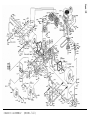
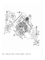
PARTS ILLUSTRATIONS
9.
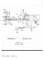
ELECTRICAL SCHEMATIC
10.
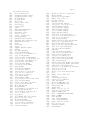
PARTS LIST
Pages
Page
Page
Pages
Pages
Pages
Pages
Page
Page
Pages
1 - 3
4
5
6-11
12-13
14 - 21
22 - 24
29
30
31 - 33
IMPORTANT - READ CAREFULLY
The Dixon ZTR Mower is both easy and fun to operate. However, any power mower
must be operated properly to be safe. It is not a toy or a recreational vehicle.
Before you start to use the mower, read the operator's manual carefully, and become
completely familiar with the controls.
The information in this operator's manual applies to all Dixon ZTR Model 502
Mowers. Your Dixon dealer will gladly provide a check-out ride, and answer any
questions.
See your dealer for warranty service, parts and repairs.
DIXON INDUSTRIES, INC.
Box 1569
Coffeyville, Kansas67337-0945
(316)251-2000
Airport Industrial Park
SAFETY
RIDING LAUNMOVJERS, IF IMPROPERLY OPERATED, CAN CAUSE SERIOUS INJURY.
The following examples are the most common causes of injury to the operator or
bystander.
1. BLADE CONTACT: The operator or bystander inserts a hand or foot into the
discharge chute or under the mower deck and into the path of the cutting
blade.
Never run the mower blades when there are people nearby.
Always turn the engine off when cleaning or working around the mower deck.
2. RUN-OVER: This situation occurs when a bystander is run-over or backed over by the
mower. The most frequently cited examples are with small children who wander
into, or are allowed to play, in an area where the mower is being operated.
Never run the mower blades when there are people nearby, especially children.
Young children should be indoors and watched by an adult.
Always look behind you before backing up.
3. TIP-OVER: This occurs when the mower tips over, usually sideways or to the rear.
This situation is due to operation of the mower on steep inclines or near a drop
off.
Mow across the slope to slightly uphill.
Mow slopes when the grass is dry and watch for bumps, holes and other
obstacles.
Test the slope with the blades off. A good rule of thumb is "Don't mow on a
slope you can't back up". Stay clear of drop-offs, especially if they are on
the down side of a slope.
4. THROWN OBJECTS: The fast spinning mower deck blade can strike stones or other
objects which can be hurled into the path of a bystander. To prevent this from
happening, never remove the safety discharge chute from the mower deck, or
operate the mower when other people are around.
5. FIRES: Most accidents of this type occur during re-fueling of the mower or placing
the mower in a storage situation. The exhaust system and related engine
components operate at very high temperatures which can ignite any fuel spilled
on or near them. Always allow the mower to cool before re-fueling or placing in
storage.
6. OPERATION BY CHILDREN: This mower is not a toy or recreational vehicle.
Never allow children to operate the mower in any manner or to ride as a
passenger.
NOTE:
The six examples are the most frequently cited injury causing situations.
Please review all the safety precautions outlined on the following pages
prior to operation of the mower. Our aim is to enhance the safe and
satisfactory use of this product.
SAFETY
Page 2
SAFETY REMINDERS: READ CAREFULLY BEFORE OPERATION
1. Wear appropriate, safe clothing when mowing - close fitting jeans or slacks and
heavy leather or safety shoes with rough soles. Never operate this mower with bare
feet or open sandals.
2. Do not operate on wet or slippery grass.
3. Always mow at the slowest speed that will cut satisfactorily.
4. Keep hands and feet away from the blade at all times.
5. Keep persons clear of the discharge chute. Do not operate mower unless deflector is
in place.
6. When mowing hills or slopes, use extreme caution. Reduce speed, do not make
sudden starts, stops or turns.
7. Always disengage blades before taking the mower across walks or objects that
project above the surface.
8. Stay alert for holes, rocks and roots in the terrain, and other hazards. Keep away
from drop-offs.
9. When the mower is not in use, turn the engine off and remove key. Never leave the
engine running unattended. Your Dixon mower is equipped with a weight-sensitive
switch that kills the engine when operator leaves the seat while blades are engaged.
"Test this important safety feature before each time mower is used.
This may be done by starting engine, engaging blades and then rising
slightly from seat. If engine does not stop, see your dealer for
necessary repair."
10. Before adjusting or servicing your mower, turn off the engine and let it cool. Be
sure all moving parts are stopped. Never run the 502 with the body open.
11. Never run the engine indoors; the fumes are dangerous.
12. Before backing your Dixon Mower; stop, turn around and look.
13. Handle gasoline with care - it is highly flammable.
A. Use approved gasoline container.
B. Never remove the fuel cap of, or add gasoline to, a running or hot engine,
or an engine that has not been allowed to cool after running. Never fill
the tank indoors and always clean up spilled gasoline.
C. Never store the mower, with gasoline in the tank, inside the building where
fumes may reach an open flame or spark. Allow the engine to cool before
storing in any enclosure.
14. Never lift lawnmower by the body; lift only by the frame.
15. Never carry passengers.
SAFETY REMINDERS: (continued)
Page 3
16. Use care when pulling loads or using heavy equipment.
A. Use only approved drawbar hitch points.
B. Limit loads to those you can safely control.
C. Do not turn sharply. Use care when backing.
17. Watch out for traffic when crossing or near roadways.
18. Keep the mower in good operating condition, and keep safety devices in place and
working.
19. Keep all nuts, bolts and screws tight to be sure the mower is in safe working
condition.
20. To reduce fire hazard, keep the engine free of grass, leaves or excessive grease.
21. The mower should be stopped and inspected for damage after striking a foreign object
or if it starts vibrating, and any damage should be repaired before restarting and
operating the mower.
22. When mowing, proceed as follows:
A. Mow only in daylight or in good artificial light.
B. Shut the engine off when removing the grass catcher or unclogging chute.
C. Check the blade mounting bolts for proper tightness at frequent intervals.
D. Never operate the machine when using medication or under the influence of
alcohol or drugs.
Page 5
SPECIFICATIONS
Chassis: 11 GA - rectangular tube.
Body:
Two piece - made of DR acrylic reinforced with fiberglass, color fast, scratch
and impact resistant. Front body contains access panels for battery service
and engine to mower deck belt removal. Rear body tilts up to allow service on
the entire drive system.
Seat:
Economically designed for operator comfort by use of high density closed cell
foam, contoured back rest and arm rests. Seat is adjustable fore and aft.
Mower Deck: 12 GA stamped steel construction, (3) blades, 50" cut width, cut height 1"
to 4" via 7 position lift handle. Self cleaning design, smoothly curved
front, aides discharge of grass.
Blade Drive: Warner electric clutch.
Drive System: (2) Sundstrand BDU - 10 L hydrostatic transmissions driven by a
permanently lubricated peerless gear box.
Engine: 18 HP Kohler twin cylinder with cast iron cylinder, pressure lubrication and
mechanical fuel pump.
Starting System: Electric by key switch operation with safety interlocks on
parking brake and blade drive clutch.
Tires: Front 11 x 4.10 x 5 smooth tread. Rear 20 x 10 x 8 turf savers.
Capacities: Fuel - 4.8 gallons total (dual tanks) with fuel gauges.
Hydrostat oil tank - 3 quart with inline 10 micron filter.
Hydrostat oil recommendation - name brand SAE (10-W-30) motor oil.
Dimensions: Width - 60" Height 45" Length - 72"
Weight - 665 lbs.
NOTE:
Additional information provided in service instruction under the
individual component.
SPECIFICATIONS SUBJECT TO CHANGE WITHOUT NOTICE........................
SET UP AND SERVICE
1.
Seat assembly instructions.
2.
Upper control lever installation.
3.
Mower deck installation.
4.
Deck leveling procedure.
5.
Final preparation.
Page 6
Page 7
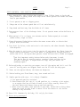
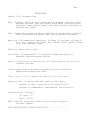
SEAT ASSEMBLY INSTRUCTIONS
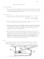
1. Assemble seat as shown in picture. Do not fully tighten the bolts which secure
left and right arm rest brackets to seat bottom until seat back and tool box are
installed. This will aid alignment of all parts.
2. Place seat assembly on rear body cover, connect seat safety switch.
3. Insert the (2) rear studs of the seat slide into the rear holes of the body
cover. Firmly hold seat assembly against body cover with one hand while rear
body is raised to fully open position. Continue to hold seat against body to
prevent damage to seat safety switch wiring.
4. Install (1) flat washer and (1) nylok nut on (1) of the rear studs extending
through body cover and seat frame, tighten a few threads to hold seat assembly in
place.
5. Position seat on front holes and install all remaining washers and nylok nuts.
Tighten all nuts fully.
SEAT ASSEMBLY INSTRUCTIONS
SEAT PACKAGE
• NOTE: HARDWARE FOR CONTROL LEVER ASSEMBLY
Page 8
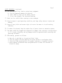
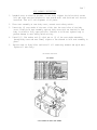
UPPER CONTROL LEVER INSTALLATION
1.
Raise rear body cover to fully open position.
2.
Install flat washer on right hand swivel plate weldment. Next install right
hand control lever, then second flat washer.
3.
Push control lever into the neutral slot and install (2) cup washers,
(1) flat washer and jam nut. (See Illustration)
4.
Tighten jam nut. Proper tightness or tension on jam nut is achieved
when swing out movement of upper control levers requires some pressure.
Levers should not fall to the side or be sloppy in movement.
5. Repeat above procedure on left side.
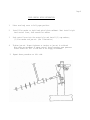
MOWER DECK INSTALLATION
Page 9
1. To remove front body from chassis, disconnect headlights and remove acorn hut in
middle of body.
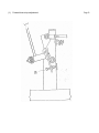
2. Install rear hanger rods on lift frame, as shown in the diagram. Slide lift plate
on hanger rods, small holes in lift plate will face rear of mower,
and start nylok nuts on each hanger rod until approximately 1/4 inch of
threads are exposed.
3. Position mower deck under chassis.
4. Place lift lever in 3rd hole from highest cut, position #5 on quadrant.
5. Using (1) of the deck support rods, insert the rod at the corner of the lift frame
and the front of the mower chassis in the groove provided on the lift frame. Pry
backwards on the lift frame enough to connect the brake link into the hole on the
tab of the lift lever. This will allow for belt installation in step #7.
6. Raise mower deck at the rear and slide (1) of the deck support rods through the
mower deck lift plate and the tabs of the mower deck. "Note" A length of 2 x 4
board turned on end and placed under the mower deck for support will make this
task easier if the installation is being done by one person, due to the weight of
the mower deck.
7. Raise front of mower deck and slide front support rod through lift frame and tabs on
mower deck. Install hair pin clips on front and rear support rods.
8. Move lift lever to lowest cut position, install engine to mower deck drive belt
on top center pulley. Check belt routing after installation to make certain
that belt is centered in groove of electric clutch pulley.
9. Move lift lever toward high cut position and remove brake link from hole on
lift lever.
10. Install deflector chute on mower deck by using nuts and bolts provided.
Never operate mower without deflector chute in place.
Page 10
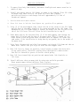
MOWER DECK LEVELING PROCEDURE
Leveling Principals:
A. There are a total of (4) threaded adjusters which will control the attitude or pitch
of the mower deck. The adjusters have lock nuts on the bottom which can be turned
up or down to raise or lower the front and rear of the mower deck. Deck should be
level or pitched slightly higher in rear.
Leveling the Deck:
A. Place the mower on a smooth level surface, check tire pressures to insure the
mower has a correct stance. Inflate tires as required:
Front - (40 - 46 lbs. maximum)
Rear - (20 - 24 lbs. maximum)
B. Remove the discharge chute from the mower deck. Rotate or turn each outer blade
tip to align with the edge of the deck or side to side.
C. Measure from the surface up to the bottom of
of the mower deck. Retain this measurement.
that measurement is the same. If adjustment
bottom of the front threaded adjuster up or
measurements are equal. Retain measurement.
the blade tip on the discharge side
Move to the opposite side and check
is required, turn the nut on the
down until both side to side
D. Rotate or turn both outer blades to align with the deck in a front to rear
manner. Move to the left rear threaded adjuster, "left rear is designated from
operator position on the mower". Turn adjuster nut up or down until rear of
mower deck is positioned level to l/8th of an inch higher than the side to side
measurement. At this time, the mower deck will hang or be suspended on (3)
points. Move the right rear adjuster and take out the slack which will be
present by turning adjuster lock nut up. Confirm the measurement used on the
left rear of the deck. Re-install discharge chute.
NOTE:
This will place the mower deck in a base measurement position. Additional
adjustment may be required to achieve desired cut for the type of grass or
conditions being mowed.
(1) - (2) Adjustment Points
Page 11
FINAL PREPARATION
1. Remove battery from chassis.
2. Fill each cell with electrolyte (acid) to ring at bottom of fill cap.
3. Allow battery to sit for (10) minutes, re-check acid level and top off any
cells that are low.
4. Trickle charge battery using a charger of less than (6) amps until all cells are
gassing freely. Hydrometer readings may be taken, if desired.
5. Install permanent battery caps and wash any accumulated acid from battery before
re-installation on chassis.
6. Observe proper battery polarity when re-connecting leads on chassis. Always
connect positive lead first.
Engine Service:
1. Final preparation of engine should be completed using engine service manual
provided with mower.
Initial Start and Hydrostat Transmission Check:
1. Final hydrostat checks have been performed at the factory, however, it is
necessary to check that the pressure relief bypass on each hydrostatic
transmission is completely released before attempting to drive mower.
2. Each hydrostat has a bypass relief pin located at the bottom front of each
hydrostatic unit. A bypass keeper is provided to allow the mower to be
rolled around without complete servicing of the unit. To accomplish this,
the bypass keeper must be positioned to depress the bypass relief pin.
After the use of bypass keeper, each must be removed from the bypass relief
pin before the unit can be operated.
Page 12
OPERATION INSTRUCTIONS
The safe and successful operation of the Model 502 will depend upon the operator having
the correct knowledge of all controls used on the mower and making good judgments about
the terrain to be mowed. Never allow anyone to operate the mower without complete
knowledge of all controls and their functions.
Sound judgment by the owner will prevent accidents.
Controls and their functions. All controls described from operators position.
PARKING BRAKE:
The parking brake used on the Model 502 is designed to hold the mower from moving and is not
intended for use in stopping the mower while it is in motion. An additional safety feature
of the parking brake is that the engine cannot be ''•'-. started unless the brake is
applied.
THE HYDROSTATIC DRIVE SYSTEM:
Allows the mower to turn on its own axis (zero radius). Each lever controls one
side of the mower. The pressure required to operate the mower is very light and a
minimum of 1/2 hour should be spent simply driving the mower in a non-mowing
application to gain the confidence necessary to mow like a pro.
LEVER MOVEMENTS:
No shifting or clutching required.
TO GO FORWARD:
Release parking brake. From neutral position, gently puch both drive levers
forward; to increase speed, move levers farther forward.
TO GO BACKWARD:
From neutral position, gently pull both drive levers toward you.
TURNING:
Turning is controlled by moving one drive lever slightly forward or rearward of the
other. To turn left, move left lever rearward of right lever. To turn "square
corners" move lever of desired direction to neutral. To turn on mower's own axis
(zero radius) reduce speed and move one lever to reverse position and the other to
forward position.
BRAKING:
To brake mower, move both levers in direction opposite of travel, release levers
to neutral, set parking brake. When stopping on incline, it may be necessary to
hold slight pressure on levers in direction opposite of slope until parking
brake is set.
GROUND SPEED:
Ground speed (controlled by movement of hand levers) must be carefully
controlled for safety and best mowing results. Never operate at high speed in
unfamiliar areas or on slopes.
CHOKE CONTROL LEVER:
Used to start a cold engine. (Engine has not been operated for a length of time)
Located on control panel to operators right.
Page 13
OPERATION INSTRUCTIONS (continued)
THROTTLE CONTROL LEVER:
Controls engine speed. (Engine should be operated at full throttle when use.d in a
mowing application, this will insure adequate cooling of the engine as well as
maintaining mower deck blade speed) Located on control panel on operators right.
MOWER DECK CUT HEIGHT LIFT LEVER:
Controls the cutting height of the mower deck. Seven positions of adjustment in which
the very top, or highest notch, is used for transporting the mower in a non-mowing
situation. Located in front of operator on the right side of mower.
BLADE DRIVE:
To engage the mower deck cutter blades, lift switch up lightly and push
forward. To disengage blades, pull switch backward. Switch is clearly
marked "on and off".
LIGHT SWITCH:
The headlights are activated by pushing the switch forward. Failure to turn off
the lights, once the engine is stopped, will result in rapid discharge of the
battery.
FUSE BLOCK:
Protection of the electrical system is by (1) 15 AMP fuse. To remove the fuse for
inspection, just simply lift upon fuse block lid. If fuse burns quickly, please
consult your dealer for inspection and repair. Never attempt to bypass the fuse by
any method.
Page 14
CARE AND MAINTENANCE - MODEL 502
This portion of the Model 502 owners manual deals with normal service items which can be
performed by the owner. Please remember that if you are in doubt as to the correct service
procedures to be followed, these and other service situations can be handled by a Dixon ZTR
Dealer who is familiar with the service of your mower.
NOTE:
, The disassembly and repair of the Sundstrand BDU 10 L hydrostatic transmissions is
best left to a qualified Sundstrand repair and service facility. These repair
centers are equipped with the necessary tools and service information to accurately
perform all service required. Due to the precision nature of these transmissions,
field repairs cannot be recommended.
MAINTENANCE SCHEDULE:
To insure a long and trouble free service life on all the components used on
the Model 502 a regular and thorough maintenance schedule should be followed.
As with any type of precision made equipment, a certain amount of initial
bedding in or seating of the components will take place. The following items
should be checked after the first (10) hours of operation and on a weekly basis,
or each (40) hours of use:
1.
2.
3.
4.
5.
Drive system chains, belts and controls.
Mower deck belts
Tire pressures.
Hydrostat oil.
Tightness of all nuts and bolts.
Refer to engine service manual provided with your mower for maintenance schedules and
procedures to be used on the engine.
Page 15
CARE AND MAINTENANCE - MODEL 502
MOWER DECK SERVICE: CUTTER BLADE REMOVAL - BELT TENSION.
"CAUTION" The removal of the cutter blades for either sharpening or replacement is best
accomplished by removing the deck assembly from the mower. Do not attempt to
raise or lift the front of the mower unless proper safety equipment is
available to support the mower. If you do not have the necessary equipment,
entrust this task to your dealer.
DECK REMOVAL:
1. Remove front belt access cover from body. Stand in front of the mower, grasp
lift quadrant lever with left hand. Move lever to align with the (5th) hole from
the bottom on the quadrant plate. At this time, connect *• brake link into hole
on lift lever. Move lift lever toward lowest cut position and remove belt from the
top of center deck hub assembly.
2. Remove the hair pin cotters from the ends of the deck support rods. Slide
deck support rods from deck while supporting deck assembly with a
suitable brace, or by the use of an assistant to hold the deck while rods
are removed. Slide deck from under chassis.
3. Reverse procedure to re-install deck assembly.
CUTTER BLADE REMOVAL:
1. Carefully place deck assembly in a manner which will allow access to the blade
bolts. Hold blade from turning while bolt is removed from the center of each hub
assembly. "Caution" wear heavy, thick gloves when holding onto cutter blade, avoid
the sharp edge of the blade.
2. When re-assembling blades to hub assemblies, fully tighten blade bolts to
a minimum of (35 ft. lbs.) torque. The use of air impact tools is recommended for
installation to insure bolt tightness.
BELT TENSION:
1. The engine to mower deck drive belt on the Model 502 is automatically held in
proper tension by springs which push the deck assembly forward, and does not
require any additional adjustment to be made. Both the belt and the idler
system should be periodically inspected due to the nature of the job they
perform.
2. Serpentine deck belt tension is maintained by a manual adjustment rod which
is located on the top of the mower deck assembly. Proper belt tension is
critical to insure cut quality. If adjustment is required, tighten lock
nut on adjustment rod until belt free play or movement between pulleys is
approximately 1/4 of an inch.
Page 16
CARE AND MAINTENANCE - MODEL 502
DRIVE SYSTEM ADJUSTMENTS:
Hydrostat Chains - Belts - Cable - Controls
Refer to the diagrams on the following pages for the location of adjustment points.
Step 1. Loosen the front and rear
adjustment bolt downward,
wheel. Chain is correctly
sprockets chain free play
down. Re-tighten mounting
mounting bolts of the hydrostat, turn the rear
which will tension the final drive chain to the rear
tensioned when at a point mid-way between the
or movement is approximately l/16th of an inch up and
bolts.
Step 2. Loosen the (2) bolts which secure the front chain adjustment, refer to
diagram, turn the front adjustment bolt downward using a 5/16th alien •;
wrench. Correct tension is as in step #1. Re-tighten bolts.
Step 3. Repeat above procedures on opposite hydrostat.
Step 4. Tighten the (2) J-bolts on the T-box mounting plate until each belt has
l/8th to l/4th of an inch free play or movement at a mid-point between the
pulleys on the hydrostats and T-box.
Step 5. Position parking brake lever in the off or disengaged position. This will allow
the belt idler used on the engine to T-box to swing fully and apply tension to
the belt. At this time, check that the cable which pulls the idler to a neutral
position has approximately 1-1/2 to 2 inches of free play. If adjustment is
required, loosen the lock nuts on the cable block and turn cable sleeve in or
out to achieve desired measurement. Re-tighten lock nuts. "NOTE" Cable must have
the above dimension with parking brake released or drive belt may slip, causing
a loss of power.
Step 6. Neutral adjustment must be checked at this time which will require the engine to
be started and the parking brake released. Swing upper control levers outward
and into neutral slots, start engine, use caution when releasing parking brake
as mower may tend to creep or move prior to re-adjustment of neutral settings on
each hydrostat. If adjustment is required, loosen lock nuts at each end of the
control rods and back off the tension bolt on each spring block. Turn control
rod in or out until neutral is obtained on each hydrostat. Re-tighten lock nuts
and tension bolts on spring blocks.
Step 7. Stop engine, move levers to drive position. Lightly push each upper control
lever forward until a resistance is felt on the lever. At this time, check that
the forward lever stops are hitting against stop block. "NOTE: Do not allow
levers to travel to completely forward without hitting stop blocks as damage to
hydrostats could result. If adjustment is required, loosen lock nut on lever
stop and turn bolt in to allow lever to hit the stop before resistance is felt in
the hydrostat.
Step 8. Start engine. Drive mower forward and observe driving condition. If mower tends
to pull to either side, re-adjust lever stop on fast side to slow that hydrostat
down and even out the ground speed. Do not speed up slow side as over stroking
of the hydrostat could result in damage to the unit. If upper control levers are
slightly off-set after this adjustment, they can be realigned by bending them
into alignment.
Page 17
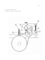
(1) HYDROSTAT MOUNTING BOLTS
(2) THREADED ADJUSTERS TO TENSION CHAINS
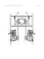
(1) ADJUSTMENT POINTS FOR T-BOX BELT TENSION
Page 18
(1)
Forward lever stop adjustment
Page 19
CARE AND MAINTENANCE - MODEL 502
Page 20
LUBRICATION:
CHASSIS AND MOWER DECK:
LOCATIONS:
SERVICE INTERVALS:
RECOMMENDED GREASE:
Number of grease zerks used (2)
(1) each front wheel caster
Every (50) hours of operation
Name brand wheel bearing or multi-purpose grease
CAUTION:
The use of compressed air pressure greasing methods
is not recommended as damage to seals and bearings could occur.
Using a hand pressure grease gun, lubricate each front caster to allow even
distribution of grease within the caster, rotate or spin each front wheel caster
after (3) pumps of the grease gun. Repeat process until the appearance of grease is
noted completely around each caster.
DRIVE CHAINS:
Primary and final drive
RECOMMENDED LUBRICANT:
SERVICE INTERVALS:
Name brand aerosol chain spray
As required for operating conditions
Remove excess dirt from chains, lubricate each chain completely by applying the lube to
the inside of each connecting link. Applying lube directly to the top of the chain
will only allow the lube to be thrown off in operation. The chains are of special
construction which use o-rings to seal a factory lubricant inside of the chain.
Additional lubrication will cushion chain to sprocket engagement. Avoid the use of
any lubricants which may damage the o-rings used on this chain.
ENGINE OIL CHANGES:
RECOMMENDATIONS:
SERVICE INTERVALS:
"Refer to separate owners manual furnished by the OIL
engine manufacturer."
Please dispose of used oils at proper collection centers. Protect your environment.
'
•
"
*
•
-
'
"
,
•
"
.
Page 21
CARE AND MAINTENANCE - MODEL 502
CLEANING THE MOWER:
A clean machine is a source of pride to the owner. However, cleaning by use of high
pressure commercial washes is not recommended. The high water pressure, combined with
solvents or alkaline detergents, can lead to corrosion of electrical components or
damage to the sealed bearings used on your mower. A better approach is the use of mild
household soaps and low water pressure. A stiff brush can be used to loosen excess
grass and dirt build up. Avoid directing water pressure onto the mower deck hub
assemblies, electrical wiring and engine components such as air filter openings. Never
wash or clean the Sundstrand BDU 10 L hydrostatic transmissions, as damage to these
units could result. To remove excess water which accumulates during washing of the
mower either blow off with compressed air, if available, or start the engine, allowing
a long enough operation time to dry thoroughly. It is advisable to engage the mower
deck for a short time to disperse all water from pulleys and belts.
Please help protect the environment by avoiding all chemicals which may damage or cause
harm to plants and animals in your area.
Page 22
TROUBLE SHOOTING
MOWER CUT QUALITY:
There are many variables that can effect the cut quality of any multi blade
mower. Type and condition of grass, ground speed, blade speed, and conditions
are some of the variables that interact creating differences in cut quality
results. In most cases, a smooth, even cut will be achieved without further
adjustment.
The Trouble Shooting Chart suggests practices and adjustments that may be
helpful in improving cut quality. Your Dixon ZTR Dealer is also available to
provide assistance to you.
SITUATION
CAUSES
REMEDY
Poor cut quality
Ground speed
Reduce mowing speed
Loose belts
Adjust per operators
manual
Engine RPM too low
Increase engine RPM to
maximum
Dull or bent blades
Sharpen or replace as
required
Unlevel mower deck
Adjust per operators
manual
Grass build-up under
mower deck
Clean out underside of
mower deck
Poor cut quality
Poor cut quality
Poor cut quality
Poor cut quality
Poor cut quality
Poor cut quality
Improper blades
Poor cut quality
Uneven tire pressures
Replace with original
equipment blades which
are designed for the
Model 501
Check and adjust as
required per operators
manual
Page 23
TROUBLE SHOOTING
DRIVE SYSTEM:
SITUATION
CAUSES
REMEDY
Mower pulls to one
side or the other
Drive adjustment
Adjust per operators
manual
Consult your dealer for
repair
Loss of drive power on
one side or the other
T-Box belts slipping
Adjust per operators
manual
Consult your dealer for
repair
Loss of power on both
wheels after being
operated for a length
of time
Belt from engine to
T-Box is slipping
Adjust per operators
manual
Consult your dealer for
repair
Poor driving
performance
Operation of mower
Review operators section
of owners manual
Oil leaks
Loose or missing hose
clamps
Tighten or replace as
required
Page 24
TROUBLE SHOOTING
ELECTRICAL SYSTEM:
SITUATION
CAUSE Blown
REMEDY
Starter will not
turn engine over
fuse
Inspect and replace fuse
If fuse continues to burn
consult your dealer for
repair
Starter will not
turn engine over
Dead battery
Charge battery
Battery discharge
Poor connections on
battery
Battery water low
Wrong battery installed in
mower
Tighten or renlace as
required
Engine electrical system
not functioning correctly
Have electrical system
checked by your dealer
Engine being operated at
too low an RPM
Increase engine RPM
Consult your dealer for
information
Battery discharge
Battery discharge
Electric clutch will
not engage mower deck
blades
Head lights do not
operate
Low battery condition
Poor connections on
clutch switch
Broken wiring
Poor connection on lights
Broken wiring
Repair or replace as
required
Consult your dealer for
repair
Repair or replace as
required
Bad bulb
Note:
Electrical system failures are generally simple in nature, always check the
obvious first and then move onto the more complicated parts used. Poor battery
service, loose connections, corrosion, frayed or broken wiring, are more likely
than component failure.
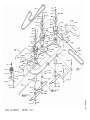
DECK ASSEMBLY
(MODEL 5O2)
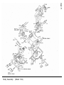
Body Assembly
(Model 502)
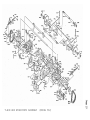
T-BOX AND HYDROSTATS ASSEMBLY
(MODEL 502)
CHASSIS ASSEMBLY
(MODEL 502)
1
a
1
C
FUEL & HYDRAULICS TANKS & FITTINGS ASSEMBLY
(MODEL 502)
a
t
>
t
Q
)
•
WIRING ASSEMBLY
(MODEL 502)
1991 ZTR 502 Parts List
1300
Belt 36" Mower Drive
1384
Tank Mount Bracket (Short)
1385
Tank Mount Bracket (Long)
1469
LH Slide Angle
1470
RH Slide Angle
1657
1668
1675
1682
1701
1714
1715
1732
1733
1734
1739
1743
1744
1745
1801
2128
2164
2173
2823
3005
3006
3007
3008
3009
3014
3019
3020
3023
3029
3031
3033
Spring - Belt Idler
Drive Pulley
Clutch Anchor
L-Rod
Wheel/Deck Hub Bearing
T-Box Drive Belt
Rear Wheel & Tire
Pulley - T-Box
Pulley - T-Box Drive
Pulley Hydrostat
Hydrostat Idler Bracket
Hydrostat Flat Idler Pulley HD
Hydrostat Drive Belt
Pulley
Seat Strap
Sleeve
Support Sprocket Spacer
Bushing
Oil Drain Assembly
5/16"-18 UNO Hex Nut
5/16"-18 X 1 1/4" HH Bolt Gr 5
1/4" -20 UNC Hex Nut
1/4" ID X 3/4" OD Flat Washer
5/16"-18 UNC X 1 3/4" HH Bolt Gr 8
l/4"-20 UNC X 3/4" HH Bolt Gr 5
5/16" Helical Lock Washer
5/16" Std Flat Wahser
1/4" Helical Lock Washer
Front Grommet
5/16"-18 UNC Acorn Nut
1/2" SAE Flat Washer
3052
3054
3056
3057
3061
3066
3072
3074
3081
3082
3087
3091
3093
3106
3118
3/32" Dia X 1" Cotter Pin
3/16" Dia X 1" Roll Pin
5/16" Fender Washer
3/8" Std Flat Washer
5/16"-18 UNC X 3/8" Soc Set Screw
3/16" Std Flat Washer
1/8" X 1 3/4" Hair Pin Cotter
5/16"-24 UNF Hex Jam Nut
#6-32 UNC Hex Nut
#6 Lock Washer
5/16"-18 UNC X 3/4" HH Bolt Gr 5
l/2"-20 UNF Hex Lug Nut
5/16"-18 UNC X 1" HH Bolt Gr 5
1/4" X 1" Spirol Pin
Disc Spring
1471
3048
3130
3133
3145
3161
3163
3169
3182
Seat Slide
3/8"-16 UNC X 1 1/2" HH Bolt
1/2" COntact Bellville Spring
#8-32 X 1/2" TR 3 Screw
#6 Std Flat Washer
5/16"-24 UNF LH Thread
1/2" Int Tooth Lock Washer
3/8"-16 X 1" HH Bolt Gr 5
Flip Lock Bushing
Page 31
3186
3187
3188
3193
3195
3196
3198
#12-24 X 3/4" Drill & Tap Screw
#10-32 Hex Nut
#10 Ext Tooth Lock Washer
Washer .43 X 1.38 X .25
Face Nut l/2"-27
Face Nut 7/16"-28
l/4"-20 Wing Nut w/Nylok
3204
3205
3206
3207
3208
3220
3224
l/4"-20 Hex Nut w/Nylok
5/16"-18 Hex Nut w/Nylok
3/8"-16 Hex Nut w/Nylok
l/2"-13 Hex Nut w/Nylok
#10-24 Hex Nut w/Nylok
7/16"-20 X 2 3/4" HH Bolt Gr 5
5/16"-18 X 1" HH Bolt w/Nylok Gr 5
3199
3225
5/16"-18 X 2 1/4" HH Bolt Gr 5
3/8"-16 X 2 1/4" HH Bolt
3231
3235
3243
3245
3247
3248
3249
3256
3257
3258
3259
3260
3262
3263
3264
3265
3266
3267
3268
9/16" Std Flat Washer
#10-24 X 5/8" Phillips Pan Hd Screw
5/16"-18 X 3 1/4" HH Bolt Gr 5
3/8"-16 Thin Profile Nylok Nut
#6-20 X 1/2" Phillips Pan Hd Screw
5/16" ID X 1/8" Thick Washer
5/8" Int Tooth Lock Washer
Snap Ring
7/16" Int Tooth Lock Washer
5/16"-18 X 4 3/4" HH Bolt Gr 8
5/16"-18 X 5" HH Bolt Gr 8
l/4"-20 X 1/2" HH Bolt Gr 5
3/4"-16 Thin Profile Nylok Nut
5/8"-ll Thin Profile Nylok Nut
5/16" Disc Spring HD
#10-24 X 3/4" Truss Hd Phillips Screw
1/4" Int Tooth Lock Washer (Not Shown)
5/16"-18 X 1 3/8" HH Bolt Gr 5
3/8"-24 X 1 1/4" HH Bolt Gr 8 w/Nylok
3274
3281
3298
3300
3315
3318
3319
3331
3338
3343
3344
3347
3348
3511
3531
3536
#6-32" X 1/2" Truss Hd Ph Screw
Clip
Washer .515 X .874 X .031
Foam Pad
1/2-20 Hex Nut W/Nylok
3/8-16 X 2 1/4: HHB Gr 8
Idler Shock Mount
M6 X PI X 8MM HHB Gr 8.8
M8 X 1.25P HWH Tap Screw
Hub Bolt-Drilled
Grease Zerk
Washer 1.033 X 1.5 X .06
5/16-18 X 3/4" Tap Screw
Adhesive Bumper Pad
Decal - OPERATING INSTRUCTIONS
Decal - DANGER
3558
3585
3589
2 Gal Tank w/Cap-Gauge
Decal - CUTTING HEIGHT
Spacer (Electric Clutch)
3599
3600
ISO Mount Assembly
Rebound Mount
3269
3270
3554
3590
5/16"-18 X 1" Soc HB
5/16"-18 X 3" Soc HB
Fuel Cap/Gauge
Key 1/4" Sq X 1/2"
Page 32
1991 ZTR 502 Parts List
3601
3602
3603
3617
3635
3644
3645
3646
3649
3653
3654
Load Mount
Spacer Tube
ISO Mount Insert
Decal - DIXON
Tee-Fuel Line
Fuel Line 5 1/2"
Fuel Line 18"
Fuel Line 20"
Fuel Line Clamp
Floor Pad Left Front
Floor Pad Right Front
3656
3669
3695
3702
3705
3706
3710
3711
3712
Floor Pad Right Rear
Decal - CAUTION
J-Bolt
Pulley
Velcro Strip - Hook
Velcro Strip - Latch
Handle Grip
Hour Meter
Handle Grip
3715
3717
3718
End Cap
3/8" Hose Clamp
5/8" Hose Clamp
3721
3723
Decal - DANGER
Decal - RESERVOIR
3747
Deflector Spring
3773
3774
LH Rod End
RH Rod End
3812
3813
3848
3852
3876
3878
3887
3890
3896
3897
Ignition Nut
Protective Cap
Cap Nut
Spring
Caster Spring
Caster Plug
Chrome Lug Nut
Bearing
Hub Cover
Decal - DIXON
4075
4124
4197
4198
4467
Fuse Holder
4568
Throttle
4701
4714
Michigan Seat 50"
Upper Wire Loom
5085
5087
5101
5112
5170
5283
5500
5501
5502
5503
5504
5507
5508
5510
5511
5512
5514
5515
5516
5522
5525
5530
5531
5537
5539
5540
Brake Band
Spacer 3/8" X 1/2"
Brake Link
Key-Sq 3/16" X 1 1/2"
Spring
Link
T-Box
Mount Plate
Mount Shim
T-Box Guide Left
T-Box Guide Right
Brake Plate Bracket Left
Brake Plate Bracket Right
Sprocket 10T
Sprocket 30T
Sprocket 10T w/Brake Drum
Brake Rod 5/16" X 2 5/8"
Idler Cable
Swivel
Brake Link Right
Brake Link Left
Control Pivot Shaft
Adjustable Collar
Control Arm Bracket
Hydrostat Support Rod
Neutral Adjust COllar
15 Amp Fuse
Solenoid w/Hardware
Ignition Switch
Blade Drive Clutch Switch
5550
5551
5553
5554
5558
5560
5561
5562
5563
5564
5565
5566
5567
5568
5575
5576
Hydrostat Left
Hydrostat Right
Spacer
Spacer
Hose Fitting
Elbow - Male
Adapter-Male (For 3/8" ID Hose)
Adapter-Male (For 5/8" ID Hose)
Tee-Cast Iron
Filter Head
Oil Filter
Hose 3/8" X 8"
Hose 3/8" X 14"
Chain-Primary (Short)
Shaft 3/4" X 8 1/4"
Spacer
4201
Switch Key (Used w/4197)
5580
Jack Shaft Bracket Left
4217
4242
4256
Battery
Deck Switch
Utility Box
4276
4446
4453
Headlight Assembly
Cover - Flex Guard
Access Cover Assembly
5583
5585
5591
5595
5608
5609
Hose 5/8" X 19"
Tab
Reservoir Assembly
Hose 5/8" X 14"
Brake Arm Left w/Bushing
Brake Arm Right w/Bushing
3655
3713
3719
3720'
3731
3772
3791
4013
4199
4216
4274
Floor Pad Left Rear
Foam Tube
Heat Shield Deflector
Tie Wrap
Control Panel
By-Pass Keeper
Model Decal
Wire Tie
Light Switch
Battery Ground Cable
Choke Cable
4569
4687
5070
5549
5577
5581
5582
Lower Wiring Loom
Battery Cover Assembly
Key 3/16" Sq X 7/8"
Brake Handle
Drive Chain-Secondary
Jack Shaft Bracket Right
Pivot Shaft Bracket
Page 33
1991ZTR 502 Parts List
5615
5623
5624
5627
5628
6011
6100
6101
6111
6113
6168
8171
8174
8176
8177
8178
8179
8180
8188
8328
8329
Connector/Elbow Assembly
Electric Clutch
Tank Cap
Left Fan
Right Fan
Mower Deck Bearing
Outer Shaft Key
Center Shaft Key
Deck Drive Belt
Blade Washer
Trash Guard
Frame 502
Upper Body Asm 502
Lower Body Asm 50"
Caster Tire 50"
Caster Rim 50"
Caster Bearing 50"
Bearing Retainer 50"
Wiring Kit 50"
Greasable Shaft 9225
Greasable Shaft 9224
8689
Mower Blade 50" Std
9023
9024
9031
9035
Engine Mount Plate - Fwd
Engine Mount Plate - Rear
Lift Tube
Lift Frame
9055
9056
9065
9066
9067
Lift Cam Left
Lift Cam Right
Lift Handle
Lift Shaft
Control Rod
9082
9089
9098
Seat Frame Pivot Rod
Control Rod Assembly
Hanger Rod
9142
9156
9157
9158
9159
9190
9212
9219
9226
Rear Lift Rod
Right Swivel Plate
Left Swivel Plate
Control Lever w/Grip Left
Control Lever w/Grip Right
Sprocket Assembly
Spring (Belt Tensioner)
Deck Hub
Deck Hub Sub Assembly
9230
9231
Outer Hub Assembly
Center Hub Assembly
9254
9261
9262
Lift Plate
Deflector
Rod
8572
8573
8576
8577
8648
9017
9049
9076
9110
9228
9242
Headlight Bulb
Headlight Bulb Socket
Rear Rim
Rear Tire
Chain Connecting Link
Seat Frame
Lift Bushing Bracket
Seat Frame Cable
Tank Cover
Deck Hub Bearing Spacer
Pulley Guard
9264
9273
9274
Deflector Sub Assembly
Mower Deck
Mower Deck Assembly
9298
9300
9309
9310
9312
9315
Caster Tube Assembly
Wheel Hub Assembly
Caster Axle LH
Caster Axle RH
Bumper Weldment
Caster Wheel & Tire
9276
Idler Arm