1
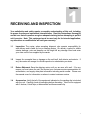
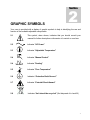
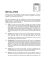
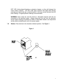
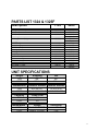
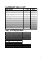
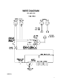
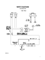
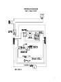
ECONOMY
OVENS
MODELS: 1310, 1320, 1321F,
1324, 1325F, 1326, 1327F
INSTALLATION AND OPERATION MANUAL
Sheldon Manufacturing Inc. P.O. Box 627 Cornelius, Oregon 97113
EMAIL: [email protected] INTERNET: http://www.Shellab.com/~Shellab
1-800-322-4897
(503) 640-3000
FAX (503) 640-1366
TABLE OF CONTENTS
SECTION 1.0
RECEIVING AND INSPECTION
SECTION 2.0
GRAPHIC SYMBOLS
SECTION 3.0
INSTALLATION
SECTION 4.0
CONTROL PANEL OVERVIEW
SECTION 5.0
PRECAUTIONS
SECTION 6.0
OPERATION
SECTION 7.0
MAINTENANCE
SECTION 8.0
TROUBLESHOOTING
SECTION 9.0
PARTS LIST
UNIT SPECIFICATIONS
WIRE DIAGRAM
REV 02/07
4861467
These units are general purpose utility ovens for professional, industrial or educational use
where the preparation or testing of materials is done at approximately atmospheric pressure
and no flammable volatile, or combustible materials are being heated. These units are not
intended for hazardous or household locations or use.
2
1
Section
RECEIVING AND INSPECTION
Your satisfaction and safety require a complete understanding of this unit, including
its proper function and operational characteristics. Read the instructions thoroughly
and be sure that all operators are given adequate training before attempting to put the
unit in service. Note: This equipment must be used only for its intended application;
any alterations or modifications will void your warranty.
1.1
Inspection: The carrier, when accepting shipment, also accepts responsibility for
safe delivery and is liable for loss or damage claims. On delivery, inspect for visible
exterior damage, note and describe on the freight bill any damage found and enter
your claim on the form supplied by the carrier.
1.2
Inspect for concealed loss or damage on the unit itself, both interior and exterior. If
any, the carrier will arrange for official inspection to substantiate your claim.
1.3
Return Shipment: Save the shipping carton until you are sure all is well. If for any
reason you must return the unit, first contact your customer service representative for
authorization, and supply data plate information including serial number. Please see
the manual cover for information on where to contact customer service.
1.4
Accessories: Verify that all of the equipment indicated on the packing slip is included
with the unit. Carefully check all packaging before discarding. Each unit is equipped
with 2 shelves, 8 shelf clips, a thermometer and thermometer clip.
3
2
Section
GRAPHIC SYMBOLS
Your oven is provided with a display of graphic symbols to help in identifying the use and
function of the available adjustable components.
2.1
This symbol, when shown, indicates that you should consult your
manual for further description or discussion of a control or user item.
2.2
Indicates "AC Power"
2.3
Indicates "Adjustable Temperature"
2.4
Indicates “Manual Control”
2.4
Indicates "Heating"
2.5
Indicates "Over Temperature"
2.6
Indicates “Protective Earth Ground ”
2.7
Indicates “Potential Shock Hazard”
2.8
Indicates “Unit should be recycled” (Not disposed of in land-fill)
4
3
Section
INSTALLATION
Local city, county, or other ordinances may govern the use of this equipment. If you have
any questions about local requirements, please contact the appropriate local agency.
Installation may be performed by the end user.
Under normal circumstances this unit is intended for use indoors, at room temperatures
between 5° and 40°C, at no greater than 80% Relative Humidity ( at 25°C) and with a supply
voltage that does not vary by more than 10%. Customer service should be contacted for
operating conditions outside of these limits.
3.1
Power: The power source must match the voltage, cycle, phase and ampere
requirements listed on the data plate (located just above the power cord on the back
side of the oven). The unit is intended for 50/60 HZ application. Make sure your
power supply matches that shown on the data plate. VOLTAGE SHOULD NOT
VARY MORE THAN 10% FROM THE DATA PLATE RATING. A separate circuit is
recommended to preclude loss of product due to overloading or circuit failure. Note
that the electrical supply to the unit must conform to all national and local electrical
codes.
3.2
Location: When selecting a site for the oven, consider conditions that may affect
performance, such as heat or cold from air vents, fast moving air currents, other
ovens, autoclaves, direct sun, etc. Avoid high traffic areas that may reduce
accessibility to the oven and allow at least 10cm between the unit and surrounding
walls or partitions that might obstruct free airflow.
3.3
Lifting/Handling: These units are heavy and care should be taken to use appropriate
lifting devices that are sufficiently rated for these loads. Units should only be lifted
from their bottom surfaces. Doors, handles, and knobs are not adequate for lifting or
stabilization. The unit should be completely restrained from tipping during lifting and
transport. All moving parts, such as shelves and trays should be removed and doors
need to be positively locked in the closed position during transfer to prevent shifting
and damage.
3.4
Leveling: The unit must sit level and solidly. The oven is equipped with nonadjustable rubber feet to raise it off the counter and prevent sliding; however, the
counter must be level to provide optimum working and safety conditions.
3.5
Cleaning: The oven was cleaned at the factory, but not sterilized. Remove all
interior parts, including shelves and shelf clips. If assembled and clean the inside of
the chamber thoroughly with a disinfectant that is appropriate for your application. DO
5
NOT USE chlorine-based bleaches or abrasive cleaners, as they will damage the
ovens interior surfaces. DO NOT USE spray cleaners that might leak through
openings and cracks and get on electrical parts or that may contain solvents that will
harm coatings. A regular periodic cleaning is recommended.
WARNING: Never clean the unit with alcohol or flammable cleaners with the unit
connected to the electrical supply. Always disconnect the unit from the electrical
service when cleaning and assure all volatile or flammable cleaners are evaporated
and dry before reattaching the unit to the power supply.
3.6
Shelves: Place shelves in the chamber at desired position. See Figure 1.
Figure 1
6
4
Section
CONTROL PANEL OVERVIEW
Figure 2
4.1
Power Switch: The main power I/O (on/off) switch controls all power to the oven. It
must be in the I or ON position before any systems are operational.
4.2
Main Temperature Controller: Marked SET TEMPERATURE, this control is
equipped with an adjustment knob and a graduated dial. The graduated dial is
marked with 10 major increments. The increments can be used as index points for
setting and returning to set point temperatures.
4.3
HEATING light: This green pilot light is marked HEAT ACTIVATED and indicates
when the element has been activated and the oven is heating. When set point is
reached the pilot light will cycle on and off as the elements maintain the temperature
selected.
4.4
Over Temperature Thermostat: Marked SET OVERTEMPERATURE, this control is
completely independent of the Main Temperature control and is equipped with an
adjustment knob that requires a flat-edged tool when making adjustments to eliminate
accidental changes. It provides safety temperature protection for the oven. If for any
reason the oven temperature rises above the Main Temperature control’s set point,
the Over Temperature Thermostat will limit the rise to approximately 10°C above the
set point selected.
4.5
Over Temperature light: This red pilot light is marked OVERTEMPERATURE
ACTIVATED and is on when the Over Temperature Thermostat has been activated
and taken control of the elements. Under normal operating conditions this pilot light
should never be on.
7
5
Section
PRECAUTIONS
This unit has been designed with a dampered vent from the chamber. In order to work
effectively and safely, some precautions will need to be taken by the operator.
5.1
In most applications, the exhaust damper will need to be open during drying or
degassing for best results.
5.2
THIS OVEN IS NOT AN EXPLOSION PROOF OVEN AND IS NOT DESIGNED TO
HANDLE COMBUSTIBLE GASSES. Do not place explosive, combustible or
flammable materials into the chamber.
5.3
Some of the out-gassed byproducts may be hazardous or unpleasant to operating
personnel. If this is the case, the exhausts should be positively ventilated to the
outside and dealt with according to local regulations. Your dealer can provide you
with a power exhaust that greatly helps under these applications.
5.4
Do not place sealed or filled containers in the oven chamber.
5.5
This oven is NOT designed for use in Class I, II, or III locations as defined by the
National Electrical Code.
5.6
This oven is not intended, nor can it be used, as a patient connected device.
8
6
Section
OPERATION
6.1
Power Supply: The power supply must be properly grounded (earthed) and correctly
sized to match the unit data plate rating. The supply voltage must match the data
plate voltage within 10%. If supplied with a detachable cord set, plug the female end
into the inlet on the unit and the male plug into the supply. Assure that units requiring
a fuse have a fuse installed.
6.2
Push the power switch to the ON position and turn the Over Temperature Thermostat
to its maximum position, clockwise so it will not interrupt the setting of the Main
Temperature control.
6.3
Place the reference thermometer through the exhaust port on top of the unit; a clip is
provided with your accessory package. See Figure 3 on the following page.
6.4
Setting Main Temperature: The operating range for this oven is ambient room
temperature + 5°C to 200°C. To set the Main Temperature Controller turn the knob to
the desired oven temperature, using the graduated dial as a reference guide. Allow
one hour for the temperature to stabilize. Using the reference thermometer, verify the
oven temperature; if it is not at the desired value, turn the control knob up or down as
needed. Allow the temperature to re-stabilize, continuing the process until the exact
desired temperature is achieved.
Note: Slight vapor or smoke may occur in the initial heat-up. This is a normal
occurrence when the oven is first brought up to temperature and protective
coatings on the element become hot.
6.5
Setting Over Temperature: As stated in section 6.2, the Thermostat should be set to
its maximum position. Now turn the control knob counterclockwise just until the
OVERTEMPERATURE ACTIVATED light comes on. Next, slowly turn the control
knob clockwise just until the light goes off. Then turn the control knob clockwise two
(2) minor scale divisions past the point where the light went out. The Over
Temperature Thermostat should now be set at approximately 10°C above the Main
Temperature set point. Note that it is not recommended that the unit be allowed to
operate using the Over Temperature Thermostat as the temperature controller for an
extended period of time. See the Troubleshooting section if the Thermostat is
activated.
9
Figure 3
10
7
Section
MAINTENANCE
Note: Prior to any maintenance or service on this unit, disconnect service cord from
the power supply.
7.1
Cleaning: Clean the oven interior on a regular basis. When washing interior of unit,
handle gasket carefully so as not to impair the positive seal. Clean the inside of the
chamber thoroughly with a disinfectant that is appropriate for your application. Make
sure to rinse the cleaned surface with a damp cloth. DO NOT USE chlorine-based
bleaches or abrasive cleaners, as they will damage the oven chamber. DO NOT
USE spray cleaners that might leak through openings and cracks and get on electrical
parts or that may contain solvents that will harm coatings.
WARNING: Never clean the unit with alcohol or flammable cleaners with the unit
connected to the electrical supply. Always disconnect the unit from the electrical
service when cleaning and assure all volatile or flammable cleaners are evaporated
and dry before reattaching the unit to the power supply.
7.2
Storage: If the unit is to be shut down for an extended period of time, wipe the
chamber clean and let dry before closing door to eliminate possibility of
contamination. If the unit is to be transported, remove shelving and trays, clasp the
door shut and disconnect the power supply. Please refer to Section 3.3, Lifting /
Handling for further direction.
7.3
No maintenance is required on the electrical components. If oven fails to operate as
specified please review Section 8.0 Troubleshooting, prior to calling customer service.
11
8
Section
TROUBLESHOOTING
TEMPERATURE
Temperature too high
1/ controller set too high-see section 6.4
2/ controller failed on – call Customer Service
3/ wiring error – call Customer Service
Chamber temp spikes over set point
and then settles to set point
Recalibrate – see section 6.3 and 6.4
Temperature too low
1/ Thermostat set too low – see section 6.5
2/ controller set too low – see section 6.4
3/ unit not recovered from door opening – wait for heating indicator
to turn off
4/ unit not recovered from power failure or being turned off – oven
will need 1 hour to warm up and stabilize
5/ element failure – see if heating indicator is on; compare current
draw to data plate
6/ controller failure – confirm with front panel light that controller is
calling for heat
7/ Thermostat failure – confirm with front panel light that it is
operating correctly
8/ wiring problem – check all functions and compare wiring to
schematic in section 9.0 - especially around any areas recently
worked on
9/ loose connection – call customer service
Unit will not heat over a temperature
that is below set point
1/ confirm amperage and voltage match data plate
2/ confirm that set point is set high enough –turn Thermostat all
the way clockwise and see if heating light or safety light comes on
3/ check connections to sensor
4/ check calibration – using independent thermometer, follow
instructions in section 6.4
Unit will not heat up at all
1/ verify that controller is asking for heat by looking for heating
indicator light – if pilot light is not on continuously at initial start up,
there is a problem with the controller
2/check amperage – amperage should be virtually at maximum
rated (data plate) amperage
3/ is the Thermostat set high enough? – for diagnostics, should be
fully clockwise with the pilot light never on
4/ has the fuse/circuit breaker blown?
12
Indicated chamber temperature
unstable
1/ ±0.1 may be normal but gravity models may vary ±2.0 degrees
2/ is ambient room temperature radically changing – either door
opening or room airflow from heaters or air conditioning ? –
stabilize ambient conditions .
3/ it may happen if exhaust stack is 100% open – adjust stack to at
least ¼ closed.
4/ calibration sensitivity – call Customer Service
5/ Thermostat set too low – be sure that it is more than five
degrees over desired set point; check if pilot is on continuously;
turn controller knob completely clockwise to see if problem solved
then follow instructions in section 6.5 for correct setting.
Will not maintain set point
1/ assure that set point is at least 5 degrees over ambient room
temperature.
2/ see if ambient is fluctuating
MECHANICAL
Door not sealing
1/ Confirm that the door gasket is aligned properly.
2/ Confirm that unit has not been damaged and that the body is
square.
OTHER
Unit or wall fuse/circuit breaker is
blown
1/ check wall power source
2/ compare current draw and compare to specs on data plate
3/ see what other loads are on the wall circuit
Unit will not turn on
1/ check wall power source
2/ check fuse/circuit breaker on unit or in wall
3/ check all wiring connections, esp. around the on/off switch
Unit is smoking – out of box
Put unit under vent and run at full power for one hour.
Contamination in chamber
1/ See cleaning procedure section 7.1
2/ Develop and follow a standard operating procedure for specific
application; include definition of cleaning technique and
maintenance schedule
13
9
SECTION
PARTS LIST 1310 , 1320 & 1321F
Description
115V
220V
Cord Set – European
Cord Set – USA
Door Gasket
Door Handle
CIRCUIT BREAKER
NA
1800516
600002
300142
1100505
1800500
101990
600002
300142
1100505
2600502
104073
9570637
9570640
9570746
X1000771
4450506
100026
4880527
103351
1750615
200021
200020
200116
5080538
5080539
200063
5080865
2600502
104073
9570642
9570644
9570802
X1000771
4450506
100026
4880528
103351
1750615
200021
200020
200116
5080538
5080539
200063
5080865
Fan 1321F
Fan Blade 1321F
Heating Element, 1310
Heating Element, 1320
Heating Element 1321F
Knob, Main Temperature
Knob, Over Temperature
Main Temperature Controller
Motor 1321F
On/Off (I/O) Switch
Over Temperature Thermostat
Pilot Light, green
Pilot Light, red
Shelf Clips
Shelf, 1310
Shelf, 1320, 1321F
Thermometer
Thermometer Clip
UNIT SPECIFICATIONS
Weight
Shipping
45 lbs.
67 lbs.
38 lbs.
60 lbs.
Dimensions
Exterior WxDxH
Interior WxDxH
Capacity
Cubic Feet
1310
1320
1310
1320
1310
1320
Temperature
1310
1320
18X16.5X21.25”
21 X 17.5 X 23.5”
Net
12 X 12 X 14”
17 X 12 X 17”
1
2
Range
Amb+5° to 200°C
Amb+5° to 200°C
Uniformity
+4°C
+4°C
14
PARTS LIST 1324 & 1325F
Description
115V
220V
Main Temperature Control
Over Temperature Conrol
Cord Set
Door Handle
Heating Element 1324
Heating Element 1325F
On/Off Switch
Knob Main Temperature
Knob Over Temperature
Pilot Light Green
Pilot Light Red
Shelf Clips
Shelf
Thermometer Clip
Thermometer
Fan Motor 1325F
Fan Blade 3” 1325F
Fan Blade 4.75” 1325F
100026
1750615
1800516
300142
9570771
9570777
103351
X1000771
4450506
200021
200020
200116
5500629
5080865
200063
4880527
104073
2600502
100026
1750615
101990
300142
9570801
9570804
103351
X1000771
4450506
200021
200020
200116
5500629
5080865
200063
4880528
104073
2600502
UNIT SPECIFICATIONS
Weight
Shipping
Net
1324
1325F
lbs.
125 lbs.
lbs.
85 lbs.
Dimensions
Exterior WxDxH
Interior WxDxH
1324
1325F
20 X 24 X 31”
20.5 X 25.25 X 31.5”
16 X 19 X 22”
16 X 17.5 X 22”
Capacity
Cubic Feet
1324
1325F
3.9
3.6
Temperature
1324
1325F
Range
Uniformity
Amb+5° to 200°C
Amb+5° to 200°C
+4°C
+4°C
15
PARTS LIST 1326 & 1327F
Description
115V
220V
Main Temperature Control
Over Temperature Conrol
Cord Set
Door Handle
Heating Element 1326
Heating Element 1327F
On/Off Switch
Knob Main Temperature
Knob Over Temperature
Pilot Light Green
Pilot Light Red
Shelf Clips
Shelf
Thermometer Clip
Thermometer
Fan Motor 1325F
Fan Blade 3” 1325F
Fan Blade 4.75” 1325F
100026
1750615
1800516
300142
9570774
9570778
103351
X1000771
4450506
200021
200020
200116
5130714
5080865
200063
4880527
104073
2600502
100026
1750615
101990
300142
9570803
9570805
103351
X1000771
4450506
200021
200020
200116
5130714
5080865
200063
4880528
104073
2600502
UNIT SPECIFICATIONS
Weight
Shipping
Net
Dimensions
Exterior WxDxH
Interior WxDxH
Capacity
Cubic Feet
1326
1327F
1326
1327F
1326
1327F
Temperature
1326
1327F
lbs.
lbs.
24 X 24 X 37”
24 X 24.5 X 37”
lbs.
lbs.
20 X 19 X 28”
20 X 17.5 X 28”
6.1
5.7
Range
Amb+5° to 200°C
Amb+5° to 200°C
Uniformity
+4°C
+4°C
16
WIRE DIAGRAM
1310 AND 1320
9850514
17
WIRE DIAGRAM
1324 AND 1325F
.
9850514
18
WIRING DIAGRAM
1321,1326,1327F
19
SHELDON MANUFACTURING, INC.
LIMITED WARRANTY
Sheldon Manufacturing, Inc., (“Manufacturer”) warrants for the original user of
this product in the U.S.A. only that this product (parts only if outside of the
U.S.A.) will be free from defects in material and workmanship for a period of
two years from the date of delivery of this product to the original user (the
“Warranty Period”). During the Warranty Period, Manufacturer, at its election
and expense, will repair or replace the product or parts that are proven to
Manufacturer’s satisfaction to be defective, or, at Manufacturer’s option,
refund the price or credit (against the price of future purchases of the
product) the price of any products that are proven to Manufacturer’s
satisfaction to be defective. This warranty does not include any labor charges
if outside of the U.S.A.
This warranty does not cover any damage due to
accident, misuse, negligence, or abnormal use. Use of Manufacturer’s product
in a system that includes components not manufactured by Manufacturer is not
covered by this warranty. This warranty is void in the event that repairs are
made by anyone other than Manufacturer without prior authorization from
Manufacturer. Any alteration or removal of the serial number on Manufacturer’s
products will void this warranty. Under no circumstances will Manufacturer be
liable for indirect, incidental, consequential, or special damages. The terms
of this warranty are governed by the laws of the state of Oregon without
regards to the principles of conflicts of laws thereof.
If any provision of
this limited warranty is held to be unenforceable by any court of competent
jurisdiction, the remainder of this limited warranty will remain in full force
and effect.
This warranty is in lieu of and excludes all other warranties or obligations,
either express or implied.
Manufacturer expressly disclaims all implied
warranties, including without limitation, the warranties of merchantability and
fitness for a particular purpose.
For fast and efficient support, please have the following information available
anytime you request service:
Model
__________
Serial No.
__________
Part No.
__________
20
Order From VWR
Call 800-932-5000
from anywhere in the U.S. and Canada
Sales & Inventory Locations:
Pacific Northwest Midwest Area
Chicago, IL
Area
Northeast Area
Southeast Area
Detroit, MI
Indianapolis, IN
Minneapolis, MN
St. Louis, MO
Boston, MA
Cincinnati, OH
Cleveland, OH
Pittsburgh, PA
Rochester, NY
Atlanta, GA
Oak Ridge, TN
Southwest Area
Gulf Area
Mid-Atlantic Area
VWR Canlab Offices
Albuquerque, NM
Denver, CO
Phoenix, AZ
San Diego, CA
San Dimas, CA
Austin, TX
Dallas, TX
Houston, TX
Lake Charles, LA
Baltimore, MD
Branford, CT
Bridgeport, NJ
S. Plainfield, NJ
Anchorage, AK
Salt Lake City, UT
San Francisco, CA
Seattle, WA
Tualatin, OR
Mississauga, Ontario
Ville Mont-Royal, Québec
Edmonton, Alberta
Or Call Direct for Specialized Service Locations:
VWR International
Switzerland
VWR Furniture Division
3000 Hadley Rd
S. Plainfield, NJ 07080
(908) 757-4045
fax: (908) 757-0313
Ruchligstrasse # 20
P.O. Box 464
Dietikon, Switzerland
CH-8953
011-41-1-745-1155
fax: 011-41-1-745-1150
P.O. Box 3405
Irving, TX 75015
(972) 714-0336
Puerto Rico
Carr. #869 Km. 1.5 M4
Royal Industrial Park
Catano, PR 00962
(787) 788-3222
fax: (787) 78804320
VWR Direct
VWR National Accounts
1310 Goshen Pkwy
W. Chester, PA 19380
(610) 431-1700
911 Commerce Ct.
Buffalo Grove, IL 60089
(800) 444-0880
Visit Our Web Site at
http://www.vwrsp.com
21