1
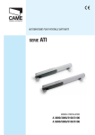
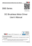
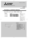
EAGLE-E7
SWING GATE OPERATOR
Eagle-E7 Swing Gate Operator
For Single & Dual Swing Gates to 16’ 700 lbs
Eagle-E7 Short Swing Gate Operator
For Single & Dual Swing Gates to 10’ 600 lbs
TABLE OF CONTENTS
UL Listings
Important Safety Information ................................................3
Requirements for UL Compliant Installation..............................3
UL 325 Classifications ...........................................................5
Required Entrapment Protection .............................................5
Installation
Operator & Gate Overview .....................................................6
Preliminary Information.........................................................6
Measurements for Mounting...................................................7
Standard Installation, Push-to-Open Installation
Mounting Brackets................................................................9
Attaching Gate Operator Arm ............................................... 10
Adjusting Open & Close Limit ............................................... 11
Wiring the Gate Operator Arm.............................................. 12
Auto Power Save Mode—Auxiliary Power ................................ 13
Loop Detectors................................................................... 14
Power Fail Operation ........................................................... 15
Battery Back-up Operation
Complete Battery Discharge
Hold-Open / Hold-Closed During Power Failure
Feature Selector................................................................. 18
Eagle Access Control Systems, Inc.
2
www.EagleOperators.com
Eagle Access Control Systems, Inc.
3
www.EagleOperators.com
Eagle Access Control Systems, Inc.
4
www.EagleOperators.com
Eagle Access Control Systems, Inc.
5
www.EagleOperators.com
INSTALLATION
OPERATOR & GATE OVERVIEW
Gate Size & Weight Requirements (Gate must operate freely)
Operator Model
Eagle-E7
Gate Leaf Width
8’
10’
16’
Gate Leaf Weight
900 lbs
800 lbs
700 lbs
Operator Model
Eagle-E7 SHORT
Gate Leaf Width
6’
10’
Gate Leaf Weight
800 lbs
600 lbs
Eagle-E7
39”
Eagle-E7
3.5”
SHORT
3.46”
5”
4.96”
31.25”
11.81”
19.5”
28.11/32”
36-7/32”
PRELIMINARY INFORMATION
Before installation, be sure that
• Gate posts, hinges, and gate construction, is sufficient to support the gates and
the gate operators,
• Gates swing freely and there is no friction or obstruction between moving parts,
• Measurement C (below) is not greater than the value shown. Modification to the
pillar is required to comply with corresponding measurements.
MODEL
EAGLE-E7
90° OPEN
130° OPEN
EAGLE-E-7 SHORT
90° OPEN
130° OPEN
Eagle Access Control Systems, Inc.
6
DIMENSION C
2-3/8”
2”
4-3/4”
2-3/4”
www.EagleOperators.com
INSTALLATION
MEASUREMENTS FOR MOUNTING
Important
Note: The following are example applications. Your application may vary.
It is the installer’s responsibility to choose the most suitable dimensions based on
site-specific issues.
Use “A Compact” dimension
only when necessary.
EAGLE-E7 — GATE LEAF
TO
16’
Opening
A
A
(Compact)
B
C
(MAX)
E
90°
7-3/4”
5”
7-3/4”
4-3/4”
36-7/32”
120°
7-3/4”
5”
5-1/2”
2-3/4”
36-7/32”
SHORT
— GATE LEAF
EAGLE-E7
TO
10’
Opening
A
A
(Compact)
B
C
(MAX)
E
90°
5”
4-1/2”
5”
2-1/4”
28-11/32”
120°
5”
4-1/2”
4-1/4”
2”
28-11/32”
Note: When attaching the Anchoring Plate & Back Bracket,
make sure the A and B measurements are correct between
the hinge axis and central bore hole on the Back Bracket.
The Back Bracket has several holes for changing the opening angle of the gate.
• Increasing the B measurement decreases the opening angle resulting in slower peripheral
speed and greater motor thrust on the gate leaf.
• Increasing measurement A increases the opening angle resulting in greater peripheral
speed and reduced motor thrust on the gate leaf.
Eagle Access Control Systems, Inc.
7
www.EagleOperators.com
INSTALLATION
MEASUREMENTS FOR MOUNTING (CONTINUED)
Optional Method: Push Gate Open
Note: The following are example applications. Your application may vary.
It is the installer’s responsibility to choose the most suitable dimensions based on sitespecific issues.
Measure the length of measurement A and B (See Dimensions This Page). Connect the Rear
Bracket and Supplemental Bracket to proper dimensions. Mount to column.
Open the gate to the full open position (Maximum 90°) and measure E.
Connect to the front bracket.
EAGLE-E7 — GATE LEAF
TO
16’
Opening
A
B
E
90°
7-3/4”
7-3/4”
36-7/32”
EAGLE-E7
SHORT
Opening
A
B
E
90°
5”
5”
28-11/32”
— GATE LEAF
TO
10’
Outside
Attach Rear
Bracket to the
Supplemental
Bracket,
Eagle Access Control Systems, Inc.
Inside
8
www.EagleOperators.com
INSTALLATION
MOUNTING BRACKETS
Attach the anchoring plate to the pillar using
the Back Bracket. Make sure the A and B
measurements are correct (See Measurements Previous Page) between the hinge axis
and central bore hole on the bracket.
Note: With the gate in the closed position, attach the Anchoring Plate & Front Bracket to
the gate leaf, making sure that the Front Bracket is level with the Back Bracket. Ensure
proper dimension E (See Measurements Previous Page).
Eagle Access Control Systems, Inc.
9
www.EagleOperators.com
INSTALLATION
ATTACHING GATE OPERATOR ARM
Step 1. Unscrew 2 screws to
remove Gear motor Housing
Cover
Gearmotor
Housing
Cover
Step 2. Unscrew 2screws to
remove Screw Drive Cover
Screw
Drive
Cover
Step 3. Mount to Front & Back Brackets
Self–locking Nut (M8)
Endless Screw Drive
Pin (M8x10)
Bushing
Pin (M8x38)
Pin (M8x50)
Back Swivel Joint
Note: Lubricating the Endless Screw
Drive and Bushing is suggested. Use
neutral grease.
Self-locking Nut (M8)
Eagle Access Control Systems, Inc.
10
www.EagleOperators.com
INSTALLATION
ADJUSTING OPEN & CLOSED LIMIT
Manual
Release
Key
OPEN LIMIT
Using the Manual Release Key, release the
gearmotor and swing the gate-leaf to the fully
open position.
Loosen the Open Limit Micro-switch Assembly.
Slide the Micro-switch Assembly along the Micro-switch Bar until it is inserted by contact on
the Micro-switch Activating Sled.
Tighten the Micro-switch Assembly using the
respective screws.
CLOSE LIMIT
Using the Manual Release Key, release the gearmotor and
swing the gate-leaf to the fully closed position.
Loosen the Closed Limit Micro-switch
Assembly.
Slide the Micro-switch Assembly
along the Micro-switch Bar until it
is in serted by contact on the
Micro-switch Activating Sled.
Tighten the Micro-switch Assembly
using the respective screws.
Eagle Access Control Systems, Inc.
11
www.EagleOperators.com
INSTALLATION
WIRING THE OPERATOR ARM
Dual Gate Operation
Motor 2
Motor 1
The Eagle-E7 electro-mechanical swing arm includes color coded wire for
convenient connection to the Diamond-DC Controller.
On dual gate application, the electro-mechanical farthest from the control
is generally considered Motor 2 and has 14’ of control wire. The arm closest to the controller is designated Motor 1 and has 8’ of control wire.
Single Gate Operation
Eagle Access Control Systems, Inc.
12
www.EagleOperators.com
INSTALLATION
AUTO POWER SAVE MODE—AUXILIARY POWER
Two 24 VDC auxiliary outputs are available for powering accessories.
Auxiliary Output 1—Use Auxiliary Output 1
for Auto Power Save mode. Auto Power Save
mode maximizes battery back-up operation and
conserves power in a solar Only
application.
When AC power is not present
Auxiliary Power
(during power failure or solar only
Output 1
application), The Diamond-DC
control board remains active for 30 seconds. After 30 seconds the Diamond-DC control board
automatically goes to “sleep” to conserve power.
Conserving power in Auto Power Save Mode
maximizes battery back-up operation and improves re-charging rate on solar only application.
Note on Auto Power Save Mode:
Output power remains always on to
the pre wired terminal strip for the
Receiver and to the Plug-in Loop
Detector for Exit Open.
For solar-only application and to maximize battery back-up cycles during power failure, connect
accessories like the photo-eye detector to Auxiliary Power
Output 1. In this way, the amp draw will be minimized during
periods (overnight) when the gate operator is not in use.
Auxiliary Output 2—Use Auxiliary Output 2
for accessories that must remain always on.
Auxiliary Output 2 is “Always On,”
even during Auto Power Save
mode.
Auxiliary Power
The current draw from Auxiliary
Output 2
Output 2 will remain constant and
will continuously draw stored power from batteries during AC power Failure and a solar only application.
Note: Some devices, like keypads, card readers and
telephone entry require their own, isolated power transformer. Eagle recommends putting such devices on
separate e power transformer as direct by the manufacturer.
Eagle Access Control Systems, Inc.
13
www.EagleOperators.com
INSTALLATION
LOOP DETECTORS
STEP 1. Using Removable Connector, Connect wire (twisted pair) from each inground loop as indicated.
W i r e ( T wi s t e d P a i r ) F r o m I n - g r o u n d L o o p C o n n e c t s t o P r o p e r L O O P W I R E I N P U T
1
2
3
4
STEP 2. Plug in Eagle Loop Detector to
Corresponding In-ground Loop as indicated
(USE ONLY EAGLE BRAND PLUG-IN
LOOP DETECTORS)
Eagle Loop Detectors Plug into Corresponding LOOP DETECTORS CONNECTIONS
1
2
3
LED INDICATORS
STEP 3. Eagle Loop
Detectors automatically adjust for proper
sensitivity.
Green LED (Upper LED)
• Steady On = Power
• Fast Blink = Shorted Loop Wire
• Slow Blink = Open Loop
Red LED (Lower LED)
• On = Vehicle Detection
Note: Eagle Brand Plug-in Loop Detectors are designed as “fail-Safe.”
Eagle Access Control Systems, Inc.
14
www.EagleOperators.com
INSTALLATION
POWER FAIL OPERATION
In the event of a power failure, your Eagle-DC Gate Operator will operate on battery
back-up until AC power is restored or the batteries are completely discharged. Alternatively your Eagle-DC gate operator can be set up to “hold open” (fail-safe) or
“hold closed” (fail-secure) until AC power is restored.
Following is the procedure for proper set-up of:
•
BATTERY BACK-UP OPERATION
•
AC Power Failure
- HOLD-OPEN or HOLD_CLOSED During AC power failure
•
COMPLETE BATTERY DISCHARGE
BATTERY BACK-UP OPERATION
When installed correctly, your Eagle-DC
Gate Operator can provide up to 100 cycles of operation during an AC power
Failure (Actual cycle count will vary
based on your gate and site conditions .
Consult your installing professional for
estimated number of cycles for your
gate system.
FOR BATTERY BACK-UP OPERATION
PWR FAIL OPERATION
Battery Back-up Operation:
Switch 1 AUTO OPEN OFF
STEP 1. Find DIP Switch Panel Labeled
“PWR FAIL OPERATION”
STEP 2. Turn Switch 1 to the OFF position
RESULT. When AC power fails, the gate will remain operational until AC power is restored or battery voltage drains
minimum (see page 17).
Eagle Access Control Systems, Inc.
15
RESET
Note:
Press RESET after
each programming
change
www.EagleOperators.com
INSTALLATION
POWER FAIL OPERATION (CONTINUED)
COMPLETE BATTERY DISCHARGE
To protect battery life, the Eagle-DC Gate Operator automatically shuts down when
battery voltage drains to the minimum allowable for safe operation.
If shut down occurs due to lost battery voltage, select the Power Fail Operation to
HOLD OPEN or HOLD CLOSED until AC power or battery voltage is restored.
HOLD OPEN During Complete Battery Discharge
STEP 1. Find DIP Switch Panel Labeled “PWR FAIL OPERATION”
STEP 2. Turn Switch 1 to the OFF position for Battery Back-up Operation (page 15)
STEP 3. Turn Switch 2 to the OFF position
RESULT. During Battery Back-up Operation, if battery voltage drains to its minimum
allowable level, the gate will move to the full open position and remain open until AC
power restored or battery voltage returns to normal.
HOLD CLOSED During Complete Battery Discharge
STEP 1. Find DIP Switch Panel Labeled “PWR FAIL OPERATION”
STEP 2. Turn Switch 1 to the OFF position for Battery Back-up Operation (page 15)
STEP 3. Turn Switch 2 to the ON position
RESULT. During Battery Back-up Operation, if battery voltage drains to its minimum
allowable level, the gate will move to full closed position and remain closed until AC
power is restored or battery voltage returns to normal.
PWR FAIL OPERATION
Complete Battery Discharge:
HOLD OPEN
Switch 2 POWER FAIL OPEN OFF
PWR FAIL OPERATION
Complete Battery Discharge:
HOLD CLOSED
Switch 2 POWER FAIL CLOSE ON
Eagle Access Control Systems, Inc.
16
www.EagleOperators.com
INSTALLATION
POWER FAIL OPERATION (CONTINUED)
HOLD-OPEN / HOLD-CLOSED During AC Power Failure
If you do not want to use Battery Back-up Operation during an AC Power Failure,
you can choose to HOLD-OPEN (fail-safe) or HOLD-CLOSED (fail-secure) your gate
until the AC Power is restored.
HOLD-OPEN During AC Power Failure
STEP 1. Find DIP Switch Panel Labeled
“PWR FAIL OPERATION”
STEP 2. Turn Switch 1 to the ON position
STEP 3. Turn Switch 2 to the OFF position
RESULT. When AC power
fails, the gate will move to
the full open position and
remain open until AC
power is restored.
PWR FAIL OPERATION
HOLD-OPEN:
Switch 1 AUTO OPEN ON
Switch 2 POWER FAIL OFF
HOLD-CLOSED During AC Power Failure
PWR FAIL OPERATION
STEP 1. Find DIP Switch Panel Labeled
“PWR FAIL OPERATION”
STEP 2. Turn Switch 1 to the ON position
STEP 3. Turn Switch 2 to the ON position
HOLD-CLOSED:
Switch 1 AUTO OPEN ON
Switch 2 POWER FAIL ON
RESULT. When AC power fails, the gate will move to the full closed position and remain open until AC power is restored.
RESET
Note:
Press RESET after
each programming
change
Eagle Access Control Systems, Inc.
17
www.EagleOperators.com
SET-UP & OPERATION
FEATURE SELECTOR
Feature Selector Switches
1.
2.
3.
4.
5.
6.
7.
8.
Master / Slave (Not Applicable/Do Not Use)
Opening Direction
Motor Brake (Not Applicable/Do Not Use)
Reverse Loop Input can be set to NO or NC
MASTER
One Pass is an anti-tailgating feature
Stop Reverse is a convenience feature that allows your radio
controls to work like a 3-button station; click to open, click to stop,
click to close
Alarm Reset allows the operator to reset itself 5 minutes after going
into overload
Close Timer
Feature Selector
Loop Wire Inputs
Reverse Loop for Use with Plug-in Loop Detector
Shadow Loop for Use with Plug-in Loop Detector
Exit Open for Use with Plug-in Loop Detector
Inputs
#1—Pre-wired Receiver Terminal Strip (3 and 4 wire receiver)
#2—Reverse Loop for External Safety Loop Detector & Photo-eye
#3—Phantom Loop for Phantom or External Shadow Loop Detector
#4—Exit Loop for Exit Probe or External Loop Detector
#5—Stop for NC Stop Button or 3-Button Station
#6—Keypad for NO Keypad, Keylock & Fire Boxes
#7—Close for 3-Button Station
#8—Edge Sensor for Edge Senor Input
Outputs
#9—Dry Contact Relay for NC or NO control of auxiliary device
#10—Mag-Lock Relay for power and control of Magnetic Gate Lock
#11—Alarm output for overload siren
#12—24 VAC Power Output for accessories
#13 & #14 Connection for 2-wire Master Slave Communication
Safety & Convenience
•
•
•
Plug-in Loop Detectors & Loop Wire Connectors
Open, Stop, Close controls on board
ERD Adjustable in the Opening and Close Direction of travel
Eagle Access Control Systems, Inc.
18
www.EagleOperators.com
Eagle Access Control Systems, Inc.
13745 Saticoy Street
Van Nuys, CA 91402
Tel: 818-779-0920 * Fax: 818-779-0093 * Toll Free: 800-708-8848
www.EagleOperators.com