1
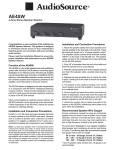
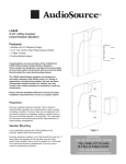
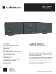
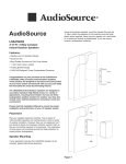
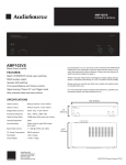
AE100VC
Impedance Matching Volume Control
Congratulations on your purchase of the AudioSource
AE100VC Impedance Matching Volume Control. This
product will allow you to install stereo speakers
throughout your home and control them, without
overloading your receiver or amplifier.
Please read this Manual to ensure the proper
installation and best performance of your AE100VC
Impedance Matching Volume Control.
4. Plug the connectors onto the circuit board terminals
being careful to observe markings for Input and Output.
If you are using a metal J-Box, insure that none of the
speaker wiring can short to the metal of the box.
Function of the AE100VC
The AE100VC features high quality audio transformers,
removable solderless connection terminals and a
computer grade double-sided glass-epoxy printed circuit
board. An impedance matching switch multiplies the
impedance the amplifier “sees” by two, four or eight
times, allowing parallel connection of multiple AE100VCs
without damaging the amplifier. Twelve knob positions
provide a maximum of 39dB of attenuation. The AE100VC
package includes a metal mounting bracket, and three
sets of color matched knobs, plastic inserts, and screws.
(White, Bone and Ivory)
Installation and Connection Procedures
Carefully choose the location for mounting the AE100VC.
For safety, and to avoid picking up hum and noise from
your electrical system, never put the AE100VC into the
same box as a light switch or dimmer.
Polarity (+/-) for the input and output speaker terminals
is clearly marked on the rear of the AE100VC. Speaker
wire is coded to identify each conductor as either
positive (+) or negative (-). This may be by color coding,
or one conductor may have a printed marking or a rib
along one edge that you will not find on the other. Identify
which type of polarity coding that your wire is using and
which conductor is positive (+) or negative (-).
1. Route the speaker cables from the amplifier and
each speaker pair to the location of the AE100VC paying
close attention to which wires connect to the speakers and
which connect to the amplifier. Mark them if needed.
2. Strip 3/8” insulation from the end of the cables and
twist the exposed ends to avoid fraying.
3. Remove the speaker and amplifier connectors from the
terminals marked Input and Output. Insert the wires into
their respective connector positions and tighten the screws.
Recommended Speaker Wire Gauges
The resistance of the speaker wire in your installation
can cause your speakers to perform at less than their
optimum quality level. Excess resistance caused by
using an undersized speaker wire can result in loss of
detail and definition in the bass region of your audio
program, as well as loss of dynamic range. Over extremely
long wire runs you may even experience a loss of high
frequency content in the audio signal.
To prevent sonic degradation in your speaker installation,
total speaker wire resistance should be kept below
0.5 ohms. The following table lists recommended speaker
wire gauge versus wire run length.
50’ or less - 16 Gauge 2-Cond. CL3 Rated
50’ - 150’ - 12 Gauge 2-Cond. CL3 Rated
150’ - 200’ - 10 Gauge 2-Cond. CL3 Rated
Note: UL rated CL3 speaker wire is recommended when
running wire inside your walls. In many localities it may be
required by code. When installing your speaker wire, avoid
running the speaker wire parallel to any 120V power lines to
avoid picking up hum and interference from the power service.
If the speaker wire needs to cross a 120V power line at a
right angle this is acceptable and will not create a problem.
If you are uncomfortable with running the speaker wire yourself
in existing construction, it is recommended that you retain a
qualified custom home installation specialist or electrician.
Setting the Impedance Matching Switch
Dimensions
Set the switches to the same setting for all AE100VCs
connected to an amplifier regardless of the number of
speakers connected to each AE100VC.
2-3/4”
70mm
4-1/2”
114mm
1 or 2X
8X
4X
2-13/16”
72mm
2-3/8”
60mm
Figure 1
Figure 1 illustrates the location of the switch which allows
the user to select impedance matching settings.
1-3/8”
35mm
Multiple AE100VCs must be wired in parallel at the
receiver or amp output. We recommend using the
AudioSource AE6SW speaker selector to achieve
this with the additional benefit of being able to turn off
unused zones at the push of a button. Simply connect
the zone outputs of the speaker selector to the volume
controls in each of the zones. Use of speaker cable
smaller than 16 gauge is not recommended.
Example: Four audio zones, each with a pair of speakers
and a volume control, totals four speaker pairs. When wired
to your 8 Ohm amplifier, all AE100VC units should have all
switches set to X4 in this configuration.
Total Number of 8 ohm Speaker Pairs Connected to Amplifier or Receiver
1
2
3
4
5
6
7
8
1X
2X
4X
4X
8X
8X
8X
8X
Switch Settings for 8 ohm Amplifiers or Receivers
Total Number of 8 ohm Speaker Pairs Connected to Amplifier or Receiver
1
2
3
4
5
6
7
8
9
10
11
12
13
14
15
16
1X
1X
2X
2X
4X
4X
4X
4X
8X
8X
8X
8X
8X
8X
8X
8X
Switch Settings for 4 ohm Amplifiers
One Year Limited Warranty
AudioSource, a division of Peak Audio Group, LLC, warrants this product against defects in materials and workmanship for a limited period of time. For a period of one
(1) year from date of original purchase, we will repair or replace the product, at our option, without charge for parts. Customer must pay for all labor
charges associated with the removal and re-installation of this product for the limited period and all parts and labor charges after the limited warranty
period expires. The limited warranty period for factory refurbished products expires after ninety (90) days from date of original purchase. This limited
warranty applies only to purchases from authorized AudioSource Retailers or Distributors. This limited warranty is extended only to the original
purchaser and is valid only to consumers in the United States.
Consumers are required to provide a copy of the original sales invoice from an authorized AudioSource Retailer or Distributor when making a claim
against this limited warranty. This limited warranty only covers failures due to defects in materials or workmanship that occur during normal use. It
does not cover failures resulting from accident, fire, flood, misuse, abuse, neglect, mishandling, misapplication, alteration, faulty installation, modification,
service by anyone other than AudioSource, or damage that is attributable to Acts of God. It does not cover costs of transportation to AudioSource or
damage in transit. The customer should return their defective product, freight prepaid and insured, to AudioSource only after receiving a Return Authorization.
Repair or replacement under the terms of this warranty does not extend the term of this warranty. Should a product prove to be defective in workmanship
or material, the consumer's sole remedies will be repair or replacement as provided under the terms of this warranty. If the defective product is
discontinued AudioSource may replace the product with an equivalent or superior product at its option. Under no circumstances shall AudioSource
be liable for loss or damage, direct, consequential or incidental, arising out of the use of or inability to use the product. There are no express warranties
other than described above.