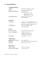
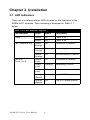
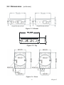
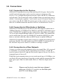
1
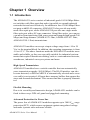
ADAM-6521 Series
Industrial Switches with 4
10/100 Mbps Ethernet Ports
and 1 Fiber Port
User Manual
Copyright
The documentation and the software included with this product are copyrighted 2006 by Advantech Co., Ltd. All rights are reserved. Advantech
Co., Ltd. reserves the right to make improvements in the products
described in this manual at any time without notice. No part of this manual may be reproduced, copied, translated or transmitted in any form or
by any means without the prior written permission of Advantech Co., Ltd.
Information provided in this manual is intended to be accurate and reliable. However, Advantech Co., Ltd. assumes no responsibility for its use,
nor for any infringements of the rights of third parties, which may result
from its use.
Acknowledgements
Intel and Pentium are trademarks of Intel Corporation.
Microsoft Windows and MS-DOS are registered trademarks of
Microsoft Corp.
All other product names or trademarks are properties of their respective
owners.
This Manual Covers the Following Models
• ADAM-6521
• ADAM-6521S
• ADAM-6521/ST
Part No.2003652104
5th Edition
Printed in Taiwan
March 2006
ADAM-6521 Series User Manual
ii
Product Warranty (2 years)
Advantech warrants to you, the original purchaser, that each of its products will be free from defects in materials and workmanship for two years
from the date of purchase.
This warranty does not apply to any products which have been repaired or
altered by persons other than repair personnel authorized by Advantech,
or which have been subject to misuse, abuse, accident or improper installation. Advantech assumes no liability under the terms of this warranty as
a consequence of such events.
Because of Advantech’s high quality-control standards and rigorous testing, most of our customers never need to use our repair service. If an
Advantech product is defective, it will be repaired or replaced at no
charge during the warranty period. For out-of-warranty repairs, you will
be billed according to the cost of replacement materials, service time and
freight. Please consult your dealer for more details.
If you think you have a defective product, follow these steps:
1.
Collect all the information about the problem encountered. (For
example, CPU speed, Advantech products used, other hardware
and software used, etc.) Note anything abnormal and list any
onscreen messages you get when the problem occurs.
2.
Call your dealer and describe the problem. Please have your manual, product, and any helpful information readily available.
3.
If your product is diagnosed as defective, obtain an RMA (return
merchandize authorization) number from your dealer. This allows
us to process your return more quickly.
4.
Carefully pack the defective product, a fully-completed Repair and
Replacement Order Card and a photocopy proof of purchase date
(such as your sales receipt) in a shippable container. A product
returned without proof of the purchase date is not eligible for warranty service.
5.
Write the RMA number visibly on the outside of the package and
ship it prepaid to your dealer.
iii
CE
This product has passed the CE test for environmental specifications
when shielded cables are used for external wiring. We recommend the
use of shielded cables. This kind of cable is available from Advantech.
Please contact your local supplier for ordering information.
FCC Class A
Note: This equipment has been tested and found to comply with the limits
for a Class A digital device, pursuant to part 15 of the FCC Rules. These
limits are designed to provide reasonable protection against harmful
interference when the equipment is operated in a commercial environment. This equipment generates, uses, and can radiate radio frequency
energy and, if not installed and used in accordance with the instruction
manual, may cause harmful interference to radio communications. Operation of this equipment in a residential area is likely to cause harmful interference in which case the user will be required to correct the interference
at his own expense.
Technical Support and Assistance
Step 1. Visit the Advantech web site at www.advantech.com/support
where you can find the latest information about the product.
Step 2. Contact your distributor, sales representative, or Advantech's
customer service center for technical support if you need additional assistance. Please have the following information ready
before you call:
- Product name and serial number
- Description of your peripheral attachments
- Description of your software (operating system, version, application software, etc.)
- A complete description of the problem
- The exact wording of any error messages
Document Feedback
To assist us in making improvements to this manual, we would welcome
comments and constructive criticism. Please send all such - in writing to:
[email protected]
ADAM-6521 Series User Manual
iv
Contents
Chapter
1 Overview .......................................................... 2
1.1
1.2
1.3
1.4
Chapter
Introduction ....................................................................... 2
Features ............................................................................. 3
Specifications .................................................................... 4
Ordering Information ........................................................ 5
2 Installation ....................................................... 8
2.1
LED Indicators .................................................................. 8
2.2
Dimensions (units:mm) ................................................... 9
2.3
2.4
Table 2.1:LED Indicator Legend ................................... 8
Figure 2.1:Bottom .......................................................... 9
Figure 2.2:Top ............................................................... 9
Figure 2.3:Front ............................................................. 9
Mounting the Module...................................................... 10
2.3.1
Choosing a Mounting Method ..................................... 10
Figure 2.4:Wall Mounting ........................................... 10
Figure 2.5:Attaching DIN Rail Bracket ....................... 11
Figure 2.6:Piggyback Stacking .................................... 11
Connections..................................................................... 12
2.4.1
2.4.2
2.4.3
2.4.4
Connection to the Devices ........................................... 12
Connection to Other Hubs or Switches ........................ 12
Connection to a Fiber Network .................................... 12
Power Connection ........................................................ 13
Figure 2.7:Power Wiring ............................................. 13
v
ADAM-6521 Series User Manual
vi
CHAPTER
1
2
Overview
This chapter gives an overview of
ADAM-6521 modules.
Sections include:
• Introduction
• Features
• Specifications
• Ordering Information
Chapter 1 Overview
1.1 Introduction
The ADAM-6521 series consists of industrial-grade 10/100 Mbps Ethernet switches with fiber ports that make it possible to expand industrial
networks fast and cost-effectively. In addition to four 10/100 Mbps Ethernet ports with RJ-45 connector, ADAM-6521 also provide one multimode fiber optic port, while ADAM-6521S provides one single-mode
fiber optic port with a SC-type connector. Using fiber optics, you can prevent noise from interfering with your system and support high-speed (100
Mbps) and long-distance (ADAM-6521: 2km; ADAM-6521/ST: 2km;
ADAM-6521S: 15km) transmissions.
ADAM-6521 modules can accept a input voltage range from +10 to 30
VDC to the terminal block. In addition, the operating temperature is from
-10 to 65° C. The above functions make the ADAM-6521 modules more
stable and reliable, so they are especially suitable for industrial environments that require Ethernet networking, such as: semiconductor factories,
warehouses, industrial conveyer systems and more.
High-Speed Transmission
ADAM-6521 modules have a switch controller that can automatically
sense transmission speeds (10/100 Mbps). The RJ-45 interface can also
be auto-detected, so MDI or MDI-X is automatically selected and a crossover cable is not required. All ports have memory buffers that support the
store-and-forward mechanism. This assures that data is properly transmitted.
Flexible Mounting
Due to its versatility and innovative design, ADAM-6521 modules can be
fixed in three ways: DIN rail, panel and piggyback mounting.
Advanced Protection for Power line
The power line of ADAM-6521 modules supports up to 3000 VDC surge
protection (EFT), which secure equipment against unregulated voltage
and make systems safer and more reliable.
ADAM-6521 Series User Manual
2
Easy Troubleshooting
There are 6 LED indicators supplied that aid troubleshooting for ADAM6521 modules. Each port has a pair of LEDs to indicate link status and
port activity. This makes it easy to monitor collisions, link status, power
failure and data reception for on-site diagnostics.
1.2 Features
• Provides 4 x 10/100 Mbps Ethernet ports with RJ-45 connector
• Provides 1 x 100 Mbps multi/single-mode fiber port with SC/ST
connector
• Supports full/half duplex flow control
• Supports MDI/MDI-X auto crossover
• Provides broadcast storm protection
• Embedded with a switch controller, supports auto-negotiation
• Embedded with the memory buffer, supports store-and-forward transmission
• Supports +10 ~ 30 VDC voltage
• Provides surge protection (EFT) 3000 VDC for power line
• Supports ESD protection 4000 VDC for Ethernet Ports
• Provides flexible mountings: DIN rail, stack, panel mounting
• Supports operating temperature: -10 ~ 65° C
• 64 KB of SRAM on chip for frame buffering
• Integrated address Look-Up Engine, supports 1K absolute MAC
addresses
3
Chapter 1
1.3 Specifications
Communications
Standard
LAN
Transmission Distance
Transmission Speed
IEEE 802.3, IEEE 802.3u, 802.3x
10/100Base-T, 100Base-FX
Ethernet: 100 m
Fiber: ADAM-6521: 2 km
ADAM-6521/ST: 2km
ADAM-6521S: 15 km
Ethernet: up to 100 Mbps
Fiber: 100 Mbps
Interface
Connectors
LED Indicators
4 x RJ-45, 1 x SC type fiber connector
(ADAM-6521, ADAM-6521S) or 1 x ST
type fiber connector (ADAM-6521/ST)
Power, Link (100Base-FX),
100/10M (Ethernet)
Power
Power Connectors
Power Consumption
Power Input
2-pin removable screw terminal
ADAM-6521: Max. 3 W
ADAM-6521/ST: Max. 3 W
ADAM-6521S: Max. 4 W
Unregulated 10 ~ 30 VDC
Mechanism
Dimensions (W x H x D)
Enclosure
Mounting
70 x 112 x 27 mm
IP30, ABS+PC with solid mounting kits
DIN 35 rail, stack, wall
Protection
ESD Protection
4,000 VDC (Ethernet)
Surge Protection (EFT)
3000 VDC (Power)
ADAM-6521 Series User Manual
4
Environment
Operating Temperature
Storage Temperature
Operating Humidity
Storage Humidity
MTBF
-10~65°C (14~149°F),
Stack : -10~60°C (14~140°F)
-20~80° C (-4~176°F)
20 ~ 95% (non-condensing)
0 ~ 95% (non-condensing)
1,150,000 hrs
Certifications
Safety
EMC
UL 60950-1, CAN/CSA-C22.2 No.60950
U.S.A.: FCC Part 15 CISPR 22
EU: EN55011, EN55022 Class A,
EN61000-3-2/3, EN55024
IEC61000-4-2/3/4/5/6/8/11
1.4 Ordering Information
• ADAM-6521
Industrial Switch with 4 10/100 Mbps Ethernet Ports & 1 Multi-mode
SC Type Fiber Optic Port
• ADAM-6521/ST
Industrial Switch with 4 10/100 Mbps Ethernet Ports & 1 Multi-mode
ST Type Fiber Optic Port
• ADAM-6521S
Industrial Switch with 4 10/100 Mbps Ethernet Ports & 1 Single-mode
SC Type Fiber Optic Port
5
Chapter 1
ADAM-6521 Series User Manual
6
CHAPTER
2
2
Installation
In this chapter, you will be given an
overview of the ADAM-6521 series
hardware installation procedure.
Sections include:
• LED Indicators
• Dimensions
• Mounting the Module
• Connections
Chapter 2 Installation
2.1 LED Indicators
There are six network status LEDs located on the top panel of the
ADAM-6521 modules. Their meaning is displayed in Table 2.1
below.
Table 2.1: LED Indicator Legend
LED Indicator
Color
Status
Description
Power
Green
On
Power is on
Green
Off
Power is off
Green/
Orange
On
Connected to network
Green/
Orange
Flashing
Networking is active
Green/
Orange
Off
Not connected to network
Green
(Link)
On
Connected to network
Green
(Link)
Flashing
Networking is active
Green
(Link)
Off
Not connected to network
Orange
(Speed)
On
Link to 100 Mbps network
Orange
(Speed)
Off
Link to 10 Mbps network
Link (100BASE-FX)
100/10M
(Ports 1 to 4)
ADAM-6521 Series User Manual
8
2.2 Dimensions (units:mm)
Figure 2.1: Bottom
Figure 2.2: Top
Figure 2.3: Front
9
Chapter 2
2.3 Mounting the Module
2.3.1 Choosing a Mounting Method
Due to its versatile and innovative design, the ADAM-6521 modules can
be:
• Fixed to a wall
• Fixed to a DIN Rail
• Piggyback Stacked
Panel Mounting
ADAM-6521 modules can be attached to a wall using the included brackets. Each bracket comes with four screws; first attach the bracket to the
bottom of the ADAM-6521 module. Next, screw the bracket to the wall.
Figure 2.4: Wall Mounting
ADAM-6521 Series User Manual
10
DIN-rail Mounting
You can mount ADAM-6521 modules on a standard 35 mm DIN-rail.
First, use two screws to attach the DIN-rail bracket to the ADAM module. Because ADAM-6521 modules use special hex head slotted shoulder
screws, the tops of the screws will be even with the front of the module.
Snap the module onto the DIN-rail.
Figure 2.5: Attaching DIN Rail Bracket
Piggyback Stack
Several ADAM-6521modules can be stacked as seen in the figure below.
Figure 2.6: Piggyback Stacking
11
Chapter 2
2.4 Connections
2.4.1 Connection to the Devices
ADAM-6521 modules have one fiber and four RJ-45 ports. Each of the
switch's twisted-pair ports can be used to connect a station or other
devices. Use a straight-through twisted-pair cable with RJ-45 connectors
on both ends. The twisted-pair cable extended from a twisted-pair port is
called a “twisted-pair segment,” and it can be up to 100 meters long. You
can connect any RJ-45 (MDI-X) station port on the switch to any device
that uses a standard network interface such as a workstation or server.
2.4.2 Connection to Other Hubs or Switches
ADAM-6521 modules have four RJ-45 ports that support connection to
10Mbps Ethernet or 100Mbps Fast Ethernet, and half or full-duplex operation. ADAM-6521 modules can be connected to other hubs or switches
via a two-pair straight-through cable or crossover cable. The connection
can be made from any port on ADAM-6521 modules (MDI-X) to other
hubs or switches either by either an MDI-X port or uplink MDI port.
ADAM-6521 modules support auto crossover to make networking easier
and more flexible. You can connect any RJ-45 (MDI-X) station port on
the switch to any device such as a switch or a bridge or router .
2.4.3 Connection to a Fiber Network
Connect to a fiber network segment with a two strand fiber. All you need
to remember is to connect the Tx (transmit) port of device I to the Rx
(receive) port of device II, and the Rx (receive) port of device I to the Tx
(transmit) port of device II.
With fiber optic transmissions you can reach speeds up to 100 Mbps, you
can block all noise interference from the system, and the transmission distance goes up to 2km for multi-mode fiber, or 15km for single-mode
fiber.
Note
Please use the dust cover that was shipped
with your ADAM-6521 modules on the fiber-optic
port if it is not being used.
ADAM-6521 Series User Manual
12
2.4.4 Power Connection
You should take the following steps to connect ADAM-6521 modules to
a power supply.
1.
Connect the power cable to a 2-pin connector.
2.
Connect the power cable to a power adapter.
Figure 2.7: Power Wiring
13
Chapter 2
ADAM-6521 Series User Manual
14