1
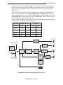
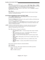
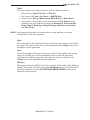
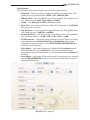
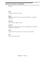
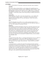
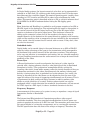
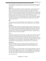
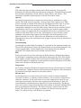
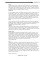
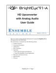
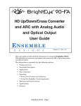
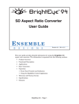
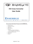
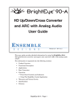
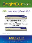
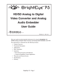
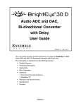
BrightEye 55
TM
Genlockable
Sync Generator and
Test Signal Generator
User Guide
ENSEMBLE
D
E
S
I
G
N
S
Revision 3.1 SW v1.0.2
This user guide provides detailed information for using the BrightEye 55
Genlockable Sync Generator and Test Signal Generator unit.
The information is organized into the following sections:
•
Product Overview
•
Functional Description
•
Applications
•
Rear Connectors
•
Operation
• Front Panel Controls and Indicators
• Using the BrightEye Control Application
•
Adjustments
•
Warranty and Factory Service
•
Specifications
•
Glossary
BrightEye 55 - Page 1
BrightEye 55 Genlockable SPG/TSG
PRODUCT OVERVIEW
BrightEye 55 is a genlockable sync and test signal generator that can be used as
either a slave or master reference generator. It can lock to house reference or it
can lock to its own internal precision standard. BrightEye 55 is well suited for
any application requiring genlocking of signals to a house reference as well as
remote trucks, desktop, and fly packs.
A variety of test signals including three color black variations, three color bar
variations, Safe Title, four sweep (multi-burst) variations, and several choices for
a user selectable test signal (selectable in BrightEye PC or Mac) are available on
the SDI and analog outputs.
A Slate ID with user-programmable text can overlay the test pattern output. The
cyclops feature adds a motion element on the video test signal, handy for live
applications.
The HD Tri Level Sync output provides reference to high definition equipment,
such as VTRs, disc recorders, and workstations. User-selectable formats include
720p, 1080i, 1080sF, and 1080p. Format selections and other controls are accessed
through the BrightEye Control application.
AES3id digital audio, analog audio with level adjustment, and embedded audio
reference outputs are provided.
A glossary of commonly used video terms is provided at the end of this manual.
FUNCTIONAL DESCRIPTION
The BrightEye 55 can lock to an external house reference or it can lock to its own
internal precision standard reference. Refer to the block diagram on the next page
while reading this section.
The Ref In BNC on the rear of the unit will accept an external PAL or NTSC
composite video signal as a reference. If a valid reference is detected on the Ref In
BNC, the unit switches to this reference automatically. The SDI, Tri Level Sync,
and AES outputs will all be synchronous relative to this reference. The overall
vertical and horizontal timing of the outputs can be adjusted in the BrightEye PC
or Mac Timing menu. Reference status is reported on the front of the unit and in
BrightEye PC or Mac. The Composite video output will have the same ScH phase
(or color framing) as the external reference.
A special case exists when simultaneously using PAL and NTSC. If the output
standard for the module is PAL and an NTSC reference is connected, BrightEye
55 will lock to the reference at the fundamental clock frequency common to PAL
and NTSC. This is referred to as “clock-locked”. The is no horizontal and vertical
relationship but BrightEye 55 will have the same frequency accuracy as the
reference and the AES audio output will be synchronous simultaneously to the
BrightEye 55 PAL output and the NTSC reference. The same case is true for an
NTSC standard with a PAL reference.
When no external reference is connected to the unit, the fundamental clock source
for BrightEye 55 is taken from a temperature compensated oscillator which
guarantees frequency accuracy to within 1 cycle of subcarrier (better than 0.2
ppm) across the full operating temperature range. In addition, because it does not
require a crystal oven, BrightEye 55 is accurate immediately upon power up. This
ensures that the BrightEye 55 outputs meet the most stringent standards.
BrightEye 55 - Page 2
BrightEye 55
TM
The external reference or master clock drives the Sync Gen block. The reference
choice is user configured for 525 (NTSC) or 625 (PAL) line rates. The standard
definition output feeds horizontal and vertical sync to the internal Test Signal
Generator.
The HD Tri Level Sync Gen block is further user configured in BrightEye PC or
Mac to one of four HD formats (1080i, 1080p, 720p, or 1080sF). The Tri Level
Sync output frame rate can be selected from two choices in BrightEye PC or Mac,
23.98/50/59.94, the most commonly used, and 24/30/60, a frame rate reserved for
use with special applications such as film.
The module will apply the selected Tri Level Sync frame rates to specific formats
and line rates as shown in the table below.
Frame Rate
23.98/50/59.94 Hz
24/30/60 Hz
Line Rate
NTSC
PAL
NTSC
PAL
1080i
59.94
50
60
50
720p
59.94
50
60
50
1080p
23.98
25
24
25
1080sF
23.98
25
24
25
HD Tri-Level
Sync Output
HD Tri-Level
Sync Gen
Uses internal Precision Reference
when no valid reference
is detected on Ref BNC
Composite Output
Composite
Encoder
Precision
Frequency
Reference
Sync
Generator
External
Reference
Input
Test Signal
Generator
SD SDI Output
Slate Text &
Cyclops
Motion Marker
Generator
Audio Embedder
Tone
Generator
Switches to External Reference
when valid reference
is detected on Ref BNC
2 Channel
D to A
6 Hz Pulse
BrightEye 55 Functional Block Diagram, Portrait View
BrightEye 55 - Page 3
AES Output
AES
Formatter
BrightEye 55 - Page 4
6 Hz Pulse
Switches to External Reference
when valid reference
is detected on Ref BNC
External
Reference
Input
Precision
Frequency
Reference
Uses internal Precision Reference
when no valid reference
is detected on Ref BNC
Test Signal
Generator
Slate Text &
Cyclops
Motion Marker
Generator
2 Channel
D to A
Tone
Generator
BrightEye 55 Functional Block Diagram, Landscape View
Sync
Generator
HD Tri-Level
Sync Gen
AES
Formatter
Audio Embedder
Composite
Encoder
AES Output
SD SDI Output
Composite Output
HD Tri-Level
Sync Output
BrightEye 55 Genlockable SPG/TSG
BrightEye 55
TM
The Sync Gen section also has an output which indicates coincidence between the
vertical intervals of the SD and HD outputs. In all formats except 1080sF/23.98,
the vertical intervals will be coincidental in every field or frame. In 1080sF/23.98
that coincidence occurs once for every 4 sF frames and every 5 SD (NTSC)
frames. Accordingly, this coincidence marker occurs at a 6 Hertz rate, and is
commonly referred to as a 6 Hz pulse.
The Tone Generator is also locked to the master clock or the external reference,
so the 48 KHz AES output will be synchronous to the video outputs. In NTSC
there are exactly 8008 audio samples in every five video frames. There will be
exactly 1920 audio samples in every PAL video frame.
The Tone Generator can be configured for a 1.0 KHz continuous tone, or an
interrupted tone which is coordinated with the Cyclops moving element. The Tone
Generator feeds the Analog Audio outputs through a precision digital to analog
converter. It feeds an AES formatter to produce a standard AES output. And
finally, it is fed to an audio embedder so that it’s present in the SDI output.
The user-selected test signal is produced in the Test Signal Gen block. The test
signal then passes to the Slate ID Text Generator which can overlay a line of user
programmable text across the test pattern. This block also has the Cyclops
Motion Marker which adds a moving element to the image.
This video signal is combined with the output of the Tone Generator to produce a
serial digital (SDI) output.
The same video signal is digitally encoded to composite video and converted to
analog form to drive the Analog Composite output.
BrightEye 55 is powered by a 12 volt DC universal power supply. This power
supply can accept an input voltage between 90 and 230 volts, at 50 or 60 Hertz. It
uses a standard IEC line cord and can be used anywhere in the world. It is
normal for the converter to be warm to the touch when operating.
BrightEye 55 - Page 5
BrightEye 55 Genlockable SPG/TSG
APPLICATIONS
BrightEye 55’s complete feature set makes it a versatile genlock sync and test
signal generator. It’s small size also makes it an excellent choice for use in mobile
applications. An example of a BrightEye 55 application is given below.
Genlocked Test Signals
With the external reference capability, BrightEye 55 can be used to input test
signals to facility devices timed to the same house reference. A number of test
signals can be fed to a router, switcher, and other devices in a facility where
genlocked timing is important.
As shown in the example below, a BrightEye 55 is fed with the house reference to
the Ref In BNC. The audio tone can be embedded into the SDI timed test signal
output and fed to an SDI router and switcher. This allows each of the test signals
to be in time with the signals fed to the other devices.
SDI Router
BrightEye 55
SDI Test Signal
with Embedded
Audio Tone
SDI Switcher
Ref In
House Ref
NTSC or PAL
BrightEye 55 Genlocked Test Signal Application
BrightEye 55 - Page 6
BrightEye 55
TM
REAR CONNECTORS
All connections to the BrightEye 55 converter are made on the rear of the unit.
Refer to the illustration below.
BrightEye 55 Rear Connectors
Power Connection
Connect a modular power supply to the 12 volt DC power input connection on the
far left of the unit. Use the locking ring to secure it.
USB Connector
The USB connector is used to provide more comprehensive control, diagnostics,
and upgrades to the unit from a PC or Mac. Use the BrightEye Control application included on CD-ROM to make adjustments as described in the OPERATION
section of this user guide.
Audio Out
The Audio Out provides two channels of an analog audio reference tone. Wiring
is done by inserting a 6 pin connector provided with the unit. Analog reference
levels can be configured from the BrightEye Control application. The pinouts for
the audio connector provided are shown in the diagram below.
Push in to release
Pin 1
+
-
Ch 1
+
-
Ch 2
Audio Output Connector
To connect audio to this connector type, strip the audio wire to about 3/8” (8 mm).
Solder tinning is not required. Push the wire into the opening at the bottom of the
connector to seat the connection. This will snap the wire into place.
To remove the wire, push in the pin above the connection with a small pointed
tool. This will release the wire from the connector.
Balanced Analog Audio Connection – to connect the audio output to an audio
XLR connector, connect the pins as follows:
•
Attach Ground from Pin 1 of the Audio Out to Pin 1 of the XLR.
•
Attach the + (plus) signal from Pin 2 of the Audio Out to Pin 2 of the XLR.
•
Attach the – (minus) signal from Pin 3 of the Audio Out to Pin 3 of the XLR.
BrightEye 55 - Page 7
BrightEye 55 Genlockable SPG/TSG
For Unbalanced Audio to a RCA Phono Input – to connect the audio output to a
consumer audio connector such as an RCA phono jack, connect the pins as
follows:
•
Attach Ground from Pin 1 of the Audio Out to the shell, Shield or Ground of
the RCA Phono jack.
•
Attach the + (plus) signal from Pin 2 of the Audio Out to the center pin of
the RCA Phono jack.
•
The – (minus) signal is not used in this application.
AES Out
The AES Out is a BNC connector that provides a digital audio output in the AES
format. The AES Output can be configured from the front panel and from the
BrightEye Control application.
HD Tri Level Sync Out
The HD Tri Level Sync Out is an output BNC connector that supplies HD
Tri Level Sync in a number of user selected formats. Either the front panel or the
BrightEye PC or Mac can be used to select the desired format. One of two
different TLS output frame rates can be selected in the BrightEye PC or Mac
Config menu (23.98/50/59.94 or 24/30/60).
SDI Out
The SDI Out is a BNC connector that provides test patterns or black in serial
digital component format. Test patterns and video standard can be selected from
the front panel as well as the BrightEye Control application. This output
conforms to the ITU-R 601 standard for serial digital video, with SMPTE 259M
serialization at 270 Mb/s. The AES audio test signals can be embedded in this
signal using BrightEye PC or Mac controls.
Cpst Out (Composite Out)
The Cpst Out is a BNC connector that presents either NTSC or PAL composite
output. This output provides the same test pattern as SDI Out, only in composite
format. The test pattern can be selected from the front panel and the BrightEye
Control application.
Ref In (Reference In)
The Ref In BNC will accept a PAL or NTSC reference input to provide an overall
genlock timing reference for the unit.
BrightEye 55 - Page 8
BrightEye 55
TM
OPERATION
Control and operation of the BrightEye 55 is performed from the front panel and
with the BrightEye Control application.
NOTE: Some control settings and parameter choices are only available with BrightEye PC or
Mac. These parameters cannot be monitored from the front panel.
Front Panel Controls and Indicators
The front panel shown in the figure below provides status indicators and control
over video and audio output.
BrightEye 55 Front Panel
Status Indicators
The following status indicators are provided on the front panel:
Std (Standard)
The currently selected output standard (NTSC or PAL) will illuminate green.
Ref (Reference)
The status indicator will be green when a valid reference is present and locked.
Video
The currently selected video pattern Black (choices include Black, Flat 20%,
Flat 80%), Bars (choices include 75% Bars, 100% Bars, SMPTE Bars), Safe
(Safe Title), Sweep (choices include Sweep, Mono Sweep, MultiBurst,
Mono Burst), or User (chosen in BrightEye PC or Mac) will illuminate green.
Selection of these different choices can be made from the front panel and in
BrightEye PC or Mac as explained next in the Controls section of this manual.
Slate
Illuminates green when the signal identification slate is enabled. To change the
Slate text ID, use the Config menu in the BrightEye Control application.
Tone
Illuminates green when analog audio tone is enabled.
BrightEye 55 - Page 9
BrightEye 55 Genlockable SPG/TSG
HD Sync
The currently selected HD Tri Level Sync format (1080i, 720p, 1080p, or 1080sF)
is illuminated green. One of two different Tri Level Sync (TLS) frame rates can be
selected in the Config menu of the BrightEye Control application as
23.98/50/59.94 (the most commonly used, default value) or 24/30/60 (for special
applications such as film).
Pwr (Power)
Illuminates green when power is applied to the unit and the internal voltage
regulator is functioning correctly.
ADJUSTING PARAMETERS FROM THE FRONT PANEL
Use the Mode, Right Arrow, and Left Arrow buttons to select and adjust
parameters from the front panel.
Pressing the Mode button activates the front panel for editing and tabs between
each section of editable parameters.
Pressing the Right Arrow or Left Arrow advances the selection within a given
section of parameters, or increases (Right Arrow) or decreases (Left Arrow) the
value of a selected parameter.
NOTE: The LED of an edited parameter will blink for 15 seconds, after which time its value is
stored in memory. If power is interrupted before this 15 second timeout period has
elapsed, the edited state will not be not saved.
The LED indicators will report the following:
•
•
•
•
•
•
Std (Standard) select – currently selected video output standard
blinks.
Ref – illuminates green when a valid NTSC or PAL reference is
detected. Off when no reference is detected.
Video – currently selected video pattern (or pattern group) output
blinks.
Slate on/off – blinks quickly when ID slate is enabled, slowly when
disabled.
Tone on/off – blinks quickly when tone is enabled, slowly when
disabled.
HD Sync select – currently selected HD Tri Level Sync format
blinks.
The controls and their indicators are described below:
Std (Standard)
This control selects the video output standard with the following choices:
NTSC – 525 NTSC standard
PAL – 625 PAL standard
BrightEye 55 - Page 10
BrightEye 55
TM
Video
This control selects the video test pattern with the following choices:
•
Black choices:, Black, Flat 20%, or Flat 80%.
•
Bar choices: 75% Bars, 100% Bars, or SMPTE Bars.
•
Sweep choices: Sweep, Mono Sweep, Multi Burst, or Mono Burst.
•
User choices – This pattern can be specified in the Test Pattern menu,
providing over eight additional patterns (Pathological, Pulse and Bar,
Ramp, Digital Blanking, Analog Blanking, Interlace, Crosshatch,
and Unit Circle).
NOTE: Mono Sweep and Mono Burst are recommended for analog applications and Sweep
and Multi Burst for SDI video applications.
Slate
This control allows the identification slate on the test signal output to be turned
on and off. The content of the slate can be configured in the Config menu in the
BrightEye Control application.
Tone
This control toggles the analog audio tone on and off. This applies to the analog
audio out, the AES out, and the embedded tone on the SDI out. Advanced
configuration of digital and analog audio reference levels is available in the
Config menu in the BrightEye Control application.
HD Sync
This control selects the HD Tri Level Sync standard. Select 1080i, 720p, 1080p, or
1080sF. This output also follows the output Standard selected, either 525 or 625.
For more information, see the FUNCTIONAL DESCRIPTION section at the
beginning of this manual.
BrightEye 55 - Page 11
BrightEye 55 Genlockable SPG/TSG
USING THE BRIGHTEYE CONTROL APPLICATION
The BrightEye PC and BrightEye Mac applications included on CD-ROM are
designed to allow you to configure and control the BrightEye 55 from a personal
computer. Installation and instructions for using this software application are
given in the PDF manual on disk. If the BrightEye 55 is connected to a computer
running this software, the following menus are available for controlling and
monitoring the unit:
Test Pattern Menu
•
Test Pattern – select the type of test pattern from the pulldown: Black,
Flat 20%, Flat 80%, 75% Bars, 100% Bars, SMPTE Bars, Safe Title,
Sweep, Mono Sweep, Multi Burst, Mono Burst, or User (defined under
User Pattern).
•
User Pattern – selects the pattern displayed when Test Pattern is set to
User. This pulldown lets you chose between: Pathological, Pulse and
Bar, Ramp, Digital Blanking, Analog Blanking, Interlace,
Crosshatch, and Unit Circle.
•
Y, Cr, and Cb Channels – these check boxes allow you to selectively
disable the output in particular luminance and color channels.
•
ID and ID Mode – these pulldowns control signal identification. Use ID to
turn signal identification On or Off. ID Mode selects between Slate Only,
Cyclops Only, or Slate & Cyclops. The content of the ID Slate can be
controlled from the Config Menu.
•
Tone and Tone Mode – these pulldowns control audio tone generation.
Tone turns tone generation On or Off. Tone Mode selects the style of tone
generated. Select between Continuous, Pop, or Beep.
•
Embedding – turning this control On embeds the audio test tone into the
SDI output. Turning it Off, does not embed the audio test tone.
BrightEye 55 - Page 12
BrightEye 55
TM
Config Menu
Use the Config menu shown below to set the following parameters:
•
Standard – select the output standard for SDI and composite video. This
pulldown lets you chose between: NTSC (525) and PAL (625).
•
HD Standard – select the HD Tri Level Sync standard. This pulldown lets
you choose between: 1080i, 720p, 1080p, or 1080sF.
•
Setup – turn Setup On or Off for 525 60Hz signals.
•
Slate Text - the contents of this text field will be displayed in the ID Slate.
Enter up to 19 characters.
•
Dig Ref Level – select the digital audio reference level. This pulldown lets
you choose between: -18dBFS or -20dBFS.
•
Analog Ref Level – select the analog audio reference level. This pulldown
lets you choose between: -10 dB, -6 dB, -4 dB, 0 dB, or +4 dB.
•
TLS Framerate – this control allows selection of the Tri Level Sync frame
rate output between 23.98/50/59.94 Hz and 24/30/60 Hz. Refer to the
discussion of this functionality in the FUNCTIONAL DESCRIPTION at
the front of this document.
•
Freq Adjust – this control temporarily enables the Freq Adjust control.
When this control is set to Allowed the user has 20 seconds to begin
adjusting the internal clock frequency, after 20 seconds this Freq Adjust is
disabled.
•
Freq Adjust – this control allows the internal timing source to be adjusted.
See the ADJUSTMENTS section of this manual for more details and the
adjustment procedure.
BrightEye 55 - Page 13
BrightEye 55 Genlockable SPG/TSG
Genlock Menu
Use the Genlock menu shown below to set the following parameters:
•
Reference – The type of external reference connected to the Ref In BNC
will be reported as No Ref, 525 Reference, or 625 Reference.
•
Ver Time – set the output timing of all output signals to match the vertical
timing in relation to the external reference connected to the Ref In BNC
in lines.
•
Hor Time – set the output timing of all output signals to match the horizontal timing in relation to the external reference connected to the Ref In
BNC in clocks.
BrightEye 55 - Page 14
BrightEye 55
TM
ADJUSTMENTS
Frequency Adjustment
The BrightEye 55 contains a precision timing source that is calibrated at the
factory to meet full specifications for timing precision. However, because clock
crystals shift frequency as they age, it may be necessary to adjust the frequency
of the internal source. This adjustment should not be necessary until after several
years of use.
Frequency Adjustment Procedure
Connect the BrightEye 55’s composite output to a vector scope that is externally
referenced to a known accurate source generator. With the external reference
enabled on the vectorscope, the vector display of the BrightEye 55 composite
signal will slowly rotate.
At this point, use the BrightEye Control Application to enable Freq Adjust and
adjust the frequency to bring the BrightEye 55 into spec by making the rotation
of its vector slow or stop.
The specification of ±1Hz of subcarrier (in either PAL or NTSC) is met if the
vector takes more than 1 second to make 1 full revolution.
The original factory adjustment is equal to a Freq Adjust value of 0.
BrightEye 55 - Page 15
BrightEye 55 Genlockable SPG/TSG
WARRANTY AND FACTORY SERVICE
Warranty
Ensemble Designs, Inc. warrants this product to be free from defect in material
and workmanship for a period of 5 years from the date of delivery. During this 5
year warranty period, Ensemble Designs, Inc. will repair any defective units at
Ensemble Designs’ expense if the unit should be determined to be defective after
consultation with a factory technician.
This warranty is not transferable. Any implied warranties expire at the expiration date of this warranty.
This warranty does not cover a defect that has resulted from improper or unreasonable use or maintenance as determined by us. This warranty is void if there is
any attempt to disassemble or adjust factory set presets without factory authorization.
Factory Service
If you require service (under warranty or not), please contact Ensemble Designs
and ask for Customer Service before you return the unit. This will allow the
service technician to provide any other suggestions for identifying the problem
and recommend possible solutions.
You may also refer to the technical support section of the Ensemble web site for
the latest information on your equipment at the URL below:
http://www.ensembledesigns.com/support
If you return equipment for repair, please get a Return Material Authorization
Number (RMA) from the factory first.
Ship the product and a written description of the problem to:
Ensemble Designs, Inc.
Attention: Customer Service RMA #####
870 Gold Flat Rd.
Nevada City, CA 95959 USA
(530) 478-1830
Fax: (530) 478-1832
[email protected]
http://www.ensembledesigns.com
Be sure to put your RMA number on the outside of the box.
BrightEye 55 - Page 16
BrightEye 55
TM
SPECIFICATIONS
Reference Input
Number
Signal Type
Return Loss
One
1V P-P PAL, NTSC, or 10 MHz
>40 dB DC to 5.5 MHz
Composite Output
Number
Signal Type
Impedance
Return Loss
Frequency Response
Output DC
K Factors
Differential Phase
SCH Phase
One
NTSC / PAL
75 1
>40 dB DC to 5.5 MHz
-0.1 dB 10 KHz to 5.0 MHz
± 50 mV
< 1.0%
< 1.0 degree
± 5 degrees
Accuracy and Timing Stability
Internal TCX0
PAL Fsc
4.43361875 MHz +/- 1 Hz
NTSC Fsc
3.579545 MHz +/- 1 Hz
601 Fs
27.000000 MHz +/- 5 Hz
Long Term Drift
<1 ppm/year
Analog Jitter
<1 ns
Digital Jitter
<0.2 UI (0.13 UI typical)
Serial Digital Output
Number
One
Signal Type
SMPTE 259M
Return Loss
> 15 dB to 270 MHz
Tri Level Sync Output
Number
One, 75 1
Type
1080i (SMPTE 274M -5, 6) 59.94, 50, 60 Hz
720p (SMPTE 296M -2, 3) 59.94, 50, 60 Hz
1080p (SMPTE 274M -9, 11) 23.98, 24, 25 Hz
1080sF (RP211 -14, 16) 23.98, 24, 25 Hz
Output DC
± 50 mV
Return Los
> 30 dB to 30 MHz
AES Output:
Number
Type
Resolution
One
AES3id, 1 KHz tone
24 bit
BrightEye 55 - Page 17
BrightEye 55 Genlockable SPG/TSG
Analog Audio Output
Number
Type
Impedance
Reference Level
One stereo pair or two mono
1 KHz tone
30 1, balanced
-10 to + 4 dBu, adjustable
General Specifications
Size
5.625” W x 0.8’’ H x 5.5’’ D
(143 mm x 20 mm x 140 mm)
including connectors
Weight
15 oz
Power
12 volts, 4 watts
(100-230 VAC modular power supply not included)
Temperature Range
0 to 40° C ambient
Relative Humidity
0 to 95%, non-condensing
Due to ongoing product development, all specifications are subject to change.
BrightEye 55 - Page 18
BrightEye 55
TM
BRIGHTEYE POWER SUPPLY INFORMATION
Below is a list of power supplies and optional items that may have come with your
BrightEye:
BEPS
BrightEye Individual Power Supply.
BEPS6
Spider Power Supply. This powers 6 single high BrightEyes or 3 double high
BrightEyes.
BEPS6-RP
Redundant Power Supply for Spider.
BERKMT
BrightEye Rack Mount. This holds 6 single high BrightEyes or 3 double high
BrightEyes, or a combination.
BEBP
BrightEye Blank Panel. Single high, for empty slots in Rack Mount.
BEAC
Analog Audio Breakout Cable.
BrightEye 55 - Page 19
BrightEye 55 Genlockable SPG/TSG
GLOSSARY
This is a brief glossary of commonly used terms associated with this product.
AES/EBU
The digital audio standard defined as a joint effort of the Audio Engineering
Society and the European Broadcast Union. AES/EBU or AES3 describes a serial
bitstream that carries two audio channels, thus an AES stream is a stereo pair.
The AES/EBU standard covers a wide range of sample rates and quantizations
(bit depths.) In television systems, these will generally be 48 KHz and either 20
or 24 bits.
Bandwidth
Strictly speaking, this refers to the range of frequencies (i.e. the width of the
band of frequency) used by a signal, or carried by a transmission channel.
Generally, wider bandwidth will carry and reproduce a signal with greater
fidelity and accuracy.
Beta
Sony Beta SP video tape machines use an analog component format that is
similar to SMPTE, but differs in the amplitude of the color difference signals. It
may also carry setup on the luminance channel.
Blanking
The Horizontal and Vertical blanking intervals of a television signal refer to the
time periods between lines and between fields. No picture information is transmitted during these times, which are required in CRT displays to allow the
electron beam to be repositioned for the start of the next line or field. They are
also used to carry synchronizing pulses which are used in transmission and
recovery of the image. Although some of these needs are disappearing, the
intervals themselves are retained for compatibility purposes. They have turned
out to be very useful for the transmission of additional content, such as teletext
and embedded audio.
CAV
Component Analog Video. This is a convenient shorthand form, but it is subject to
confusion. It is sometimes used to mean ONLY color difference component
formats (SMPTE or Beta), and other times to include RGB format. In any case, a
CAV signal will always require three connectors – either Y/R-Y/B-Y, or R/G/B.
Checkfield
A Checkfield signal is a special test signal that stresses particular aspects of
serial digital transmission. The performance of the Phase Locked-Loops (PLLs) in
an SDI receiver must be able to tolerate long runs of 0’s and 1’s.Under normal
conditions, only very short runs of these are produced due to a scrambling
algorithm that is used. The Checkfield, also referred to as the Pathological test
signal, will “undo” the scrambling and cause extremely long runs to occur. This
test signal is very useful for testing transmission paths.
BrightEye 55 - Page 20
BrightEye 55
TM
Chroma
The color or chroma content of a signal, consisting of the hue and saturation of
the image. See also Color Difference.
Component
In a component video system, the totality of the image is carried by three
separate but related components. This method provides the best image fidelity
with the fewest artifacts, but it requires three independent transmission paths
(cables). The commonly used component formats are Luminance and Color
Difference (Y/Pr/Pb), and RGB. It was far too unwieldy in the early days of color
television to even consider component transmission.
Composite
Composite television dates back to the early days of color transmission. This
scheme encodes the color difference information onto a color subcarrier. The
instantaneous phase of the subcarrier is the color’s hue, and the amplitude is the
color’s saturation or intensity. This subcarrier is then added onto the existing
luminance video signal. This trick works because the subcarrier is set at a high
enough frequency to leave spectrum for the luminance information. But it is not a
seamless matter to pull the signal apart again at the destination in order to
display it or process it. The resultant artifacts of dot crawl (also referred to as
chroma crawl) are only the most obvious result. Composite television is the most
commonly used format throughout the world, either as PAL or NTSC. It is also
referred to as Encoded video.
Color Difference
Color Difference systems take advantage of the details of human vision. We have
more acuity in our black and white vision than we do in color. This means that
we need only the luminance information to be carried at full bandwidth, we can
scrimp on the color channels. In order to do this, RGB information is converted to
carry all of the luminance (Y is the black and white of the scene) in a single
channel. The other two channels are used to carry the “color difference”. Noted as
B-Y and R-Y, these two signals describe how a particular pixel “differs” from
being purely black and white. These channels typically have only half the
bandwidth of the luminance.
Decibel (dB)
The decibel is a unit of measure used to express the ratio in the amplitude or
power of two signals. A difference of 20 dB corresponds to a 10:1 ratio between
two signals, 6 dB is approximately a 2:1 ratio. Decibels add while the ratios
multiply, so 26 dB is a 20:1 ratio, and 14 dB is a 5:1 ratio. There are several
special cases of the dB scale, where the reference is implied. Thus, dBm refers to
power relative to 1 milliwatt, and dBu refers to voltage relative to .775V RMS.
The original unit of measure was the Bel (10 times bigger), named after
Alexander Graham Bell.
BrightEye 55 - Page 21
BrightEye 55 Genlockable SPG/TSG
dBFS
In Digital Audio systems, the largest numerical value that can be represented is
referred to as Full Scale. No values or audio levels greater than FS can be reproduced because they would be clipped. The nominal operating point (roughly corresponding to 0 VU) must be set below FS in order to have headroom for audio
peaks. This operating point is described relative to FS, so a digital reference level
of -20 dBFS has 20 dB of headroom before hitting the FS clipping point.
EDH
Error Detection and Handling is a method to verify proper reception of an SDI or
HD-SDI signal at the destination. The originating device inserts a data packet in
the vertical interval of the SDI signal and every line of the HD signal which
contains a checksum of the entire video frame. This checksum is formed by
adding up the numerical values of all of the samples in the frame, using a
complex formula. At the destination this same formula is applied to the incoming
video and the resulting value is compared to the one included in the transmission.
If they match, then the content has all arrived with no errors. If they don’t, then
an error has occurred.
Embedded Audio
Digital Audio can be carried along in the same bitstream as an SDI or HD-SDI
signal by taking advantage of the gaps in the transmission which correspond to
the horizontal and vertical intervals of the television waveform. This technique
an be very cost effective in transmission and routing, but can also add complexity
to signal handling issues because the audio content can no longer be treated independently of the video.
Frame Sync
A Frame Synchronizer is used to synchronize the timing of a video signal to
coincide with a timing reference (usually a color black signal that is distributed
throughout a facility). The synchronizer accomplishes this by writing the
incoming video into a frame buffer memory under the timing direction of the sync
information contained in that video. Simultaneously the memory is being read
back by a timing system that is genlocked to a house reference. As a result, the
timing or alignment of the video frame can be adjusted so that the scan of the
upper left corner of the image is happening simultaneously on all sources. This is
a requirement for both analog and digital systems in order to perform video
effects or switch glitch-free in a router. Frame synchronization can only be
performed within a single television line standard. A synchronizer will not convert
an NTSC signal to a PAL signal, it takes a standards converter to do that.
Frequency Response
A measurement of the accuracy of a system to carry or reproduce a range of signal
frequencies. Similar to Bandwidth.
IEC
The International Electrotechnical Commission provides a wide range of
worldwide standards. They have provided standardization of the AC power connection to products by means of an IEC line cord. The connection point uses three
flat contact blades in a triangular arrangement, set in a rectangular connector.
The IEC specification does not dictate line voltage or frequency. Therefore, the
BrightEye 55 - Page 22
BrightEye 55
TM
user must take care to verify that a device either has a universal input (capable
of 90 to 230 volts, either 50 or 60 Hz), or that a line voltage switch, if present, is
set correctly.
Interlace
Human vision can be fooled to see motion by presenting a series of images, each
with a small change relative to the previous image. In order to eliminate the
flicker, our eyes need to see more than 30 images per second. This is accomplished in television systems by dividing the lines that make up each video frame
(which run at 25 or 30 frames per second) into two fields. All of the odd-numbered
lines are transmitted in the first field, the even-numbered lines are in the second
field. In this way, the repetition rate is 50 or 60 Hz, without using more
bandwidth. This trick has worked well for years, bit it introduces other temporal
artifacts. Motion pictures use a slightly different technique to raise the repetition
rate from the original 24 frames that make up each second of film—they just
project each one twice.
IRE
Video level is measured on the IRE scale, where 0 IRE is black, and 100 IRE is
full white. The actual voltages that these levels correspond to can vary between
formats.
ITU-R 601
This is the principal standard for standard definition component digital video. It
defines the luminance and color difference coding system that is also referred to
as 4:2:2. The standard applies to both PAL and NTSC derived signals. They both
will result in an image that contains 720 pixels horizontally, with 486 vertical
pixels in NTSC, and 576 vertically in PAL. Both systems use a sample clock rate
of 27 Mhz, and are serialized at 270 Mb/s.
Jitter
Serial digital signals (either video or audio) are subject to the effects of jitter. This
refers to the instantaneous error that can occur from one bit to the next in the
exact position each digital transition. Although the signal may be at the correct
frequency on average, in the interim it varies. Some bits come slightly early, other
come slightly late. The measurement of this jitter is given either as the amount of
time uncertainty or as the fraction of a bit width. For 270 Mb/s video, the
allowable jitter is 740 picoseconds, or 0.2 UI (Unit Interval – one bit width).
Luminance
The “black & white” content of the image. Human vision had more acuity in
luminance, so television systems generally devote more bandwidth to the
luminance content. In component systems, the luminance is referred to as Y.
Multi-mode
Multi-mode fibers have a larger diameter core than single mode fibers (either 50
or 62.5 microns compared to 9 microns), and a correspondingly larger aperture. It
is much easier to couple light energy into a multi-mode fiber, but internal reflections will cause multiple “modes” of the signal to propagate down the fiber. This
will degrade the ability of the fiber to be used over long distances.
See also Single-mode.
BrightEye 55 - Page 23
BrightEye 55 Genlockable SPG/TSG
NTSC
The color television encoding system used in North America was originally
defined by the National Television Standards Committee. This American standard
has also been adopted by Canada, Mexico, Japan, Korea, and Taiwan. (This
standard is referred to disparagingly as Never Twice Same Color.)
Optical
An optical interface between two devices carries data by modulating a light
source. This light source is typically a laser or laser diode (similar to an LED)
which is turned on and off at the bitrate of the datastream. The light is carried
from one device to another through a glass fiber. The fiber’s core acts as a
waveguide or lightpipe to carry the light energy from one end to another. Optical
transmission has two very significant advantages over metallic copper cables.
Firstly, it does not require that the two endpoint devices have any electrical connection to each other. This can be very advantageous in large facilities where
problems with ground loops appear. And secondly, and most importantly, an
optical interface can carry a signal for many kilometers or miles without any
degradation or loss in the recovered signal. Copper is barely useful at distances of
just 1000 feet.
Oversampling
A technique to perform digital sampling at a multiple of the required sample rate.
This has the advantage of raising the Nyquist Rate (the maximum frequency that
can be reproduced by a given sample rate) much higher than the desired
passband. This allows more easily realized anti-alias filters.
PAL
During the early days of color television in North America, European broadcasters developed a competing system called Phase Alternation by Line. This slightly
more complex system is better able to withstand the differential gain and phase
errors that appear in amplifiers and transmission systems. Engineers at the BBC
claim that it stands for Perfection At Last.
Progressive
An imaging scanning technique that progresses through all of the lines of a frame
in a single pass. Computer monitors all use progressive displays. This contrasts to
the Interlace technique common to television systems.
Return Loss
An idealized input or output circuit will exactly match its desired impedance
(generally 75 ohms) as a purely resistive element, with no reactive (capacitive or
inductive) elements. In the real world, we can only approach the ideal. So, our
real inputs and outputs will have some capacitance and inductance. This will
create impedance matching errors, especially at higher frequencies. The Return
Loss of an input or output measures how much energy is returned (reflected back
due to the impedance mismatch.) For digital circuits, a return loss of 15 dB is
typical. This means that the energy returned is 15 dB less than the original
signal. In analog circuits, a 40 dB figure is expected.
BrightEye 55 - Page 24
BrightEye 55
TM
RGB
RGB systems carry the totality of the picture information as independent Red,
Green, and Blue signals. Television is an additive color system, where all three
components add to produce white. Because the luminance (or detail) information
is carried partially in each of the RGB channels, all three must be carried at full
bandwidth in order to faithfully reproduce an image.
ScH Phase
Used in composite systems, ScH Phase measures the relative phase between the
leading edge of sync on line 1 of field 1 and a continuous subcarrier sinewave.
Due to the arithmetic details of both PAL and NTSC, this relationship is not the
same at the beginning of each frame. In PAL, the pattern repeats every 4 frames
(8 fields) which is also known as the Bruch Blanking sequence. In NTSC, the
repeat is every 2 frames (4 fields.) This creates enormous headaches in editing
systems and the system timing of analog composite facilities.
SDI
Serial Digital Interface. This term refers to inputs and outputs of devices that
support serial digital component video. This generally means standard definition
at 270 Mb/s. The use of “HD-SDI” is beginning to appear to indicate High
Definition Serial Digital Video at 1.485 Gb/s.
SMPTE
The Society of Motion Picture and Television Engineers is a professional organization which has done tremendous work in setting standards for both the film
and television industries. The term “SMPTE’” is also shorthand for one particular
component video format - luminance and color difference.
Single Mode
A single mode (or mono-mode) optical fiber carries an optical signal on a very
small diameter (9 micron) core surrounded with cladding. The small diameter
means that no internally reflected lightwaves will be propagated. Thus only the
original “mode” of the signal passes down the fiber. A single mode fiber used in an
optical SDI system can carry a signal for up to 20 kilometers. Single mode fibers
require particular care in their installation due to the extremely small optical
aperture that they present at splice and connection points.
See also Multi-mode.
TBC
A Time Base Corrector is a system to reduce the Time Base Error in a signal to
acceptable levels. It accomplishes this by using a FIFO (First In, First Out)
memory. The incoming video is written into the memory using its own jittery
timing. This operation is closely associated with the actual digitization of the
analog signal because the varying position of the sync timing must be mimicked
by the sampling function of the analog to digital converter. A second timing
system, genlocked to a stable reference, is used to read the video back out of the
memory. The memory acts as a dynamically adjusting delay to smooth out the
imperfections in the original signal’s timing. Very often a TBC will also function
as a Frame Synchronizer.
See also: Frame Sync.
BrightEye 55 - Page 25
BrightEye 55 Genlockable SPG/TSG
Time Base Error
Time base error is present when there is excessive jitter or uncertainty in the line
to line output timing of a video signal. This is commonly associated with playback
from video tape recorders, and is particularly severe with consumer type heterodyne systems like VHS. Time base error will render a signal unusable for
broadcast or editing purposes.
Tri Level Sync
An analog sync reference signal that is used in High Definition systems. Tri Level
Sync is constructed with three signal levels, the sync pulses extend above and
below a mid-level average voltage (the blanking level). Unlike conventional
analog sync which is bi-level, the proper 50% pickoff point is already identified in
Tri Level Sync. This contributes to lower jitter in digital systems.
YUV
Strictly speaking, YUV does not apply to component video. The letters refer to the
Luminance (Y), and the U and V encoding axes using in the PAL composite
system. Since the U axis is very close to the B-Y axis, and the V axis is very close
to the R-Y axis, YUV is often used as a sort of shorthand for the more longwinded “Y/R-Y/B-Y”.
Y/Cr/Cb
In digital component video, the luminance component is Y, and the two color difference signals are Cr (R-Y) and Cb (B-Y).
Y/Pr/Pb
In analog component video, the image is carried in three components. The
luminance is Y, the R-Y color difference signal is Pr, and the B-Y color difference
signal is Pb.
BrightEye 55 - Page 26