1
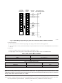
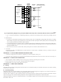
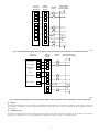
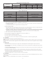
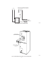
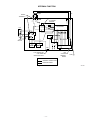
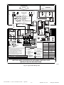
Installation Instructions
Smart Heat
Heat Pump
Heater Packages
KFCEH
NOTE: Read the entire instruction manual before starting the installation.
This symbol → indicates a change since last issue.
SAFETY CONSIDERATIONS
Installing and servicing of heating and air conditioning equipment can be hazardous due to system pressures and electrical components. Only
trained personnel should install or service heating and air conditioning equipment.
Untrained personnel can perform basic maintenance functions such as cleaning coils, or cleaning and replacing filters. All other operations should
be performed by trained personnel. When working on heating and air conditioning equipment, observe precautions in literature, on tags, and on
labels attached to the unit.
Follow all safety codes. Wear safety glasses and work gloves. Have a fire extinguisher available.
.
Recognize safety information. This is the safety-alert symbol
When you see this symbol on the unit and in instructions or manuals, be alert to the potential for personal injury.
Understand the signal words DANGER, WARNING, and CAUTION. These words are used with the safety-alert symbol. DANGER identifies the
most serious hazards which will result in severe personal injury or death. WARNING signifies hazards which could result in personal injury or
death. CAUTION is used to identify unsafe practices, which would result in minor personal injury or product and property damage. NOTE is used
to highlight suggestions which will result in enhanced installation, reliability, or operation.
INTRODUCTION
This instruction covers installation of Smart Heat electric heater packages Part No. KFCEH0101H10, KFCEH0201H15, and KFCEH0301H20 into
FA4, FB4, FC4, and FX4 fan coils. Check unit rating plates for compatibility of fan coil and electric heater combinations. See Table 1 for heater
package usage.
NOTE: The Smart Heat option is for use only on heat pumps, and is not approved for any other application.
Table 1—Accessory Heater Usage
ELECTRIC HEATER
PART NO.
KFCEH0101H10
KFCEH0201H15
KFCEH0301H20
MODELS FA4, FB4, FC4, FX4
SIZE
018-036
024-048
030-070
DESCRIPTION
10 kw, Non-Fused
15 kw, Fused
20 kw, Fused
DESCRIPTION AND USAGE
The Smart Heat electric heater package options allow the addition of accessory heaters and related controls to models FA4, FB4, FC4, and FX4
fan coils with heat pump outdoor units only. See Table 1 for heater package usage.
The Smart Heat electric heater package options enhance performance of heat pump by managing the electric heat. Heating elements are staged
on individually as required to maintain dwelling set point temperature. The controller will adjust the indoor blower speed tap to reduce airflow
in the ultra comfort mode.
The controller is not a substitute for good installation and ductwork practices. All ductwork should be free of air leakage and insulated.
Performance may not be satisfactory if good practices are not followed.
NOTE: Electric heaters require a minimum airflow. See Table 2 for minimum motor speed selection before installing. There is a 1-in. minimum
clearance to combustible materials for the first 36 in. of ductwork on all fan coils with 20-kw packages, and 024, 033, and 038 size fan coils with
15-kw heater packages.
WARNING: Before beginning any installation or modification, be sure the main electrical disconnect switch(es) is in
the OFF position. Tag the disconnect with a suitable warning label. Electrical shock can cause personal injury or death.
INSTALLATION
PROCEDURE 1—INSTALL ELECTRIC HEATER ASSEMBLY
NOTE: Ensure heater coils are not deformed or damaged during heater installation.
1. Make sure power is off.
2. Remove blower access panel of fan coil unit.
Form:
AG-FCEH-07
Cancels:
AG-FCEH-03
Printed in U.S.A.
5-00
Catalog No.
63FC-EH5
INSERT FUSE
BOX TAB HERE
COVER PLATE
OR
KNOCKOUT
SINGLE-CIRCUIT
GROUND LUG
FUSE BOX TAB
DIMPLE
FUSE BOX
DUAL-CIRCUIT
GROUND LUG
SLOTS
HEATER/CUTOUT
COVER
FUSE COVER
WIRE TIE
(REMOVE ON
LARGE FAN COILS)
A94126
Fig. 1—Installation of Heater Package and Printed-Circuit Board
3. Disconnect power leads, pigtail leads (black and yellow), fan leads (yellow, red, blue, and black), primary and secondary transformer leads,
and all low-voltage control wires. Remove existing printed-circuit board (PCB). Remove existing heater package or cooling control plate
from fan coil. (See Fig. 1.)
4. Insert heater assembly into front of fan coil until element rods engage holes in heat shield.
5. Attach heater control plate to fan coil using 2 screws. (See Fig. 1.)
Table 2—Minimum Motor Low-Speed Tap Selection
FAN COIL
FA4, FB4, FC4
018
024
030
033
036
038
042
048
060
070
FX4
—
—
030
—
036
—
042
048
060
—
10
Med*
Low
Low
Low
Low
—
—
—
—
—
HEATER KW
15
—
Med†
Low
Med†
Low
Low†
Low
Low
—
—
20
—
—
Med†
Low†
Low†
Low†
Low†
Low†
Low†
Low†
* High speed with 208v.
† Requires a minimum 1-in. clearance to combustible materials for the first 36 in. of ductwork. On 2-speed fan models, low speed may be used in place of medium (Med)
speed.
PROCEDURE 2—ATTACH FUSE BOX
For 15- and 20-kw fused heater:
1. After installing heater assembly, attach fuse assembly to side of fan coil unit by inserting fuse box tab between insulation and left side of
unit and fan deck, if necessary.
2. Mount front of assembly to side flange with 2 screws provided. On fan coil units size 042 and larger, remove wire tie that shortens wire
length between heater and fuses.
3. Close cover by engaging dimples in fuse box. (See Fig. 1.)
PROCEDURE 3—PRINTED-CIRCUIT BOARD (PCB) AND BRACKET INSTALLATION
CAUTION: Avoid direct contact with the PCB. The PCB is a static sensitive device. Handle by the sheet metal bracket
only. Static discharge can damage the PCB.
—2—
CEPL130121-01
MOV1
FS1
Z1
C14
R39
C4
D5
R23
C6
R7
R6
Y
R8
Z4
C11
R17
U1
LED1
R2
W2D
W 2T
Z3
R5
R40
R18
R11
U2
O
R16
R19
R10
C9
C8
JW6
G
R12
R20
C12
C10
R13
W3
C7
R15
D3
JW4
JW5
CLIP JUMPER FOR
HIGH SPEED FAN ONLY
B
C
K1
R14
R26
E
R29
D4
E
B
Q1
Q2
B
C
E D1
C
Q3
®
K2
6
DUMMY
T2
9
240 VAC
F1
T3
COMMON
DUMMY
®
HSCI
FAN
240
VAC
F2
JW2
(HIGH FAN
ONLY WHEN
CUT)
AUX+
P1
8
7
LR40061
5
4
T1
3
XFORM
Yo
AUX–
2
R27
JW8
R4
1
D2
1
JW1
(CUT WHEN
OUTDOOR
THERMOSTAT
IS USED)
JW1
Z2
R41
JW2
R36
R37
C15
C3
R38
C2
C13
R21
R9
JW7
R22
C
Z5
C5
CESS430121-01A
LOW VOLTAGE
TERMINAL
BOARD
R
R3
1
R28
R25
R24
ST1
R1
R30
JW3
SEC1
RECEPTACLE
CES0130025 –
SEC2
HI
LO
K3
A94127
Fig. 2—Printed-Circuit Board (PCB)
1. Install control board assembly into slots on blower deck. (See Fig. 1.)
2. Insert screw through mounting bracket into lip of fan coil and tighten.
PROCEDURE 4—ELECTRICAL CONNECTIONS
Refer to unit instructions for recommended wiring procedures. Install wiring in accordance with all applicable local and national codes. See Table
3 for recommended wire and fuse sizes. Harness contains both 24-v control, and high-voltage wiring.
1. Connect heater harness plug to receptacle on PCB. (See Fig. 2.) A secure connection MUST be made between plug and receptacle. Plug
will interlock with receptacle when properly seated.
2. Connect yellow common fan lead to PCB fan terminal F1.
3. Connect desired cooling speed to PCB terminal HI.
4. Connect lower speed desired for reduced heat pump speed to terminal LO. (See Tables 2, 4, and 5.)
5. Connect unused fan speed tap to dummy terminal F2.
6. For 24-v control system connections to unit PCB:
Refer to unit wiring instructions and diagrams for recommended wiring procedures. (See Fig. 3, 4, 5, 6, 7 and 8.) Use 18-gage thermostat
wire for low-voltage control field wiring. When over 100 ft, increase wire gage.
NOTE: PCB staging is automatic and controls its own algorithm. However, if local codes require using an outdoor thermostat (see applicable
outdoor unit Installation Instructions), cut jumper wire JW1 on PCB. (See Fig. 2.) All heaters are limited to 2 levels of heat with jumper JW1 cut.
(See Table 6 for capacity.)
CAUTION: Miswiring of transformer to printed circuit board will destroy both transformer and printed circuit board.
7. High-voltage supply connections to heater:
Unit wiring label is for 230-v operation. On transformers without primary leads, use the yellow and black pigtails provided with kit. Connect
yellow lead between transformer "C" and PCB "T1". Connect black lead between transformer 230 or 208 and PCB "T3". On transformers
with primary leads, connect primary transformer black lead to T1, blue lead to T2, and red lead to T3. When using 208v, connect red primary
lead to T2 and blue lead to T3.
8. Connect secondary transformer wires to PCB terminals SEC1 and SEC2. (See Fig. 2.)
NOTE: Heater supply circuit wire size and overcurrent protection must comply with National Electric Code (NEC) and Underwriters Laboratories
(UL) "Branch Circuit" requirements. (See Tables 3, 4, and 5.) Wires and overcurrent protection, integral to the heater, are not required to meet
branch circuit requirements. Internal circuit protection of 60 amps maximum is acceptable.
—3—
Table 3—Electric Heater Package Data
WATTS @ 240V: 9000
KFCEH0101H10
230-v
208-v
SINGLE CIRCUIT
HEATER AMPS
MCA*
MOP†
75°C WIRE SIZE (AWG)
MAXIMUM WIRE LENGTH
(FT)
35.9
48.3
50
8
32.5
44.0
45
8
61
60
KFCEH0201H15
230v
WATTS @ 240v: 15,000
208v
SINGLE CIRCUIT
HEATER AMPS
MCA
MOP
75°C WIRE SIZE (AWG)
MAXIMUM WIRE LENGTH
(FT)
59.9
80.3
90
4
54.2
73.2
80
4
92
92
DUAL CIRCUIT
WATTS @ 240v: 11,000
L1/L2
HEATER AMPS
MCA
MOP
75°C WIRE SIZE (AWG)
MAXIMUM WIRE LENGTH
(FT)
L3/L4
HEATER AMPS
MCA
MOP
75°C WIRE SIZE (AWG)
MAXIMUM WIRE LENGTH
(FT)
43.9
54.9
60
6
39.7
49.7
50
8
85
53
WATTS @ 240v: 4000
16.0
25.4
30
10
14.4
23.4
25
10
74
73
WATTS @ 240v: 20,000
KFCEH0301H20
230v
208v
SINGLE CIRCUIT
HEATER AMPS
MCA
MOP
75°C WIRE SIZE (AWG)
MAXIMUM WIRE LENGTH
(FT)
79.9
106.7
110
2
72.3
97.2
100
3
111
87
DUAL CIRCUIT
WATTS @ 240v: 10,000
L1/L2
HEATER AMPS
MCA
MOP
75°C WIRE SIZE (AWG)
MAXIMUM WIRE LENGTH
(FT)
L3/L4
HEATER AMPS
MCA
MOP
75°C WIRE SIZE (AWG)
MAXIMUM WIRE LENGTH
(FT)
40.0
56.8
60
6
36.2
52.0
60
6
82
81
WATTS @ 240v: 10,000
*MCA — Minimum Circuit Ampacity
†MOP — Maximum Overcurrent Protection
—4—
40.0
50.0
50
8
36.2
45.3
50
8
93
93
TYPICAL
HEAT PUMP
THERMOSTAT
INDOOR
CONTROL
BOARD
OUTDOOR
SPLICE
R
R
R
C
C
C
Y
Y
G
G
O
O
O
E
W2D
W2
W2
W2T
L
W3
SINGLE-SPEED HEAT
PUMP DEFROST BOARD
JW1
Y0
Y
L
A94128
Fig. 3—System Wiring Diagram Using A Typical Indoor Thermostat, With No Outdoor Thermostat
a. Nonprotected heaters
(1.) The 10-kw heater can be wired for single supply only. Supply circuits connect to heater pigtail leads.
(2.) The 10-kw heaters can use separate field-installed, factory-authorized disconnect kit Part No. KFADK0101DSC which installs in
fan coil.
b. Fused heater
(1.) The 15- and 20-kw heaters can be wired for single- or dual-supply circuits.
(2.) Single supply circuit wiring requires a factory-authorized, single point adapter kit Part No. KFASP0101SPK.
Table 4—Color Code For Motor Lead Wires
MOTOR SPEED TAP
WIRE COLOR
Common
Yellow
High
Black
Medium
Blue (3-speed only)
Low
Red (Blue — 2-speed motors)
Table 5—Fan Motor Speed Taps
UNIT
MOTOR SPEED
FA4A018-036
2
COOL SPEED
High
FA4A042-070
3
Medium
FB4A, FC4B, FX4A (All Sizes)
3
Medium
9. Ground Connections
→
WARNING: According to NEC, ANSI/NFPA 70, and local codes, the cabinet must have an uninterrupted or unbroken
ground to minimize personal injury if an electrical fault should occur. The ground may consist of electrical wire or metal
conduit when installed in accordance with existing electrical codes. (See Ground/Conduit Note below.) Failure to follow this
warning could result in electrical shock, fire, or death.
NOTE: Use UL-listed conduit and conduit connector for connecting supply wire(s) to unit to obtain proper grounding. If conduit connection uses
reducing washers, a separate ground wire must be used. Grounding may also be accomplished by using grounding lugs provided in control box.
a. For non-protected or single-circuit heaters, 1 equipment ground connection is provided on fan coil units. (See Fig. 1.)
—5—
INDOOR
CONTROL
BOARD
MODEL HP
THERMOSTAT
OUTDOOR
SPLICE
24 VAC HOT
R
R
R
24 VAC COMM
C
C
C
COOL / HEAT
STAGE 1
Y/Y2
Y
FAN
G
G
RVS COOLING
O/W2
O
O
W2D
W2
HEAT STAGE 2
W/W1
W2T
SINGLE-SPEED HEAT
PUMP DEFROST BOARD
JW1
W3
Y0
Y
A97217
Fig. 4—System Wiring Diagram Using A Corporate Model Heat Pump Indoor Thermostat, With No Outdoor Thermostat
b. For 15- and 20-kw fused heaters, an additional ground lug is provided on fuse mounting bracket for dual-circuit grounding. (See Fig.
1.)
10. Mode Selection
a. In some cases it is desirable for the PCB to operate in efficiency mode. This is accomplished by cutting jumper JW2. (See Fig. 2.) Jumper
JW2 is labeled. Cut jumper for high speed fan only. In this mode, the PCB only energizes the HI speed tap selection. With jumper JW2
cut, fan speed tap terminal LO becomes a dummy terminal.
b. In some instances when fan coil heater calls for a minimum speed selection of MED (blue) and desired cooling speed is MED (blue),
fan speed tap MED (blue) should be located on PCB fan terminal labeled HI, and JW2 jumper must be cut. Store unused fan taps on
terminals DUMMY and LO.
c. When 018 size fan coil unit is used on 208v, black speed tap must be connected to HI and JW2 must be cut.
11. Accessories
Use accessory kit Part No. KFAIR0101ACR to attach electronic air cleaner (EAC) or humidifier. (See Fig. 9.) Follow accessory kit
Installation Instructions.
PROCEDURE 5—ATTACH WIRING DIAGRAM AND RATING LABEL
1. Attach new wiring label to fan coil blower. Completely cover old wiring label. (See Fig. 12.)
2. Attach new heater rating label over existing electrical information rating label located on front access door of fan coil unit. (See Fig. 10.)
PROCEDURE 6—INSTALLATION VERIFICATION
1. After completion of heater installation, check to ensure proper connections and routings have been made.
2. Ensure all electrical covers are in place, and proper labels have been applied.
3. Reinstall blower access door before turning on unit power.
PROCEDURE 7—SMART HEAT OPERATION
A. Cooling
Smart Heat option controls the cooling mode in the same manner as conventional heat pumps are controlled. The fan has a 90 sec blower off delay
at the end of a cooling cycle.
B. Heat Pump Heating
Smart Heat option does not control heating in the conventional method. The PCB energizes the compressor 30 sec before the indoor fan is
energized. This allows the indoor coil to heat up eliminating cold-blow on start-up.
The electric heat is staged-on to allow continuous operation of heat pump and electric resistance heat below the balance point (below the point
where the heat pump cannot maintain dwelling temperature without supplemental heat) independent of outdoor thermostats.
Although the PCB has provisions for an outdoor thermostat, it is not needed for staging. On cycle down, indoor fan remains on 60 sec to recover
heat stored in indoor coil.
—6—
TYPICAL
HEAT PUMP
THERMOSTAT
INDOOR
CONTROL
BOARD
OUTDOOR
SPLICE
R
R
R
C
C
C
Y
Y
G
G
O
O
O
E
W2D
W2
W2
W2T
L
W3
SINGLE-SPEED
HEAT PUMP
DEFROST BOARD
CUT
JW1
Y0
ODT
Y
L
A94129
Fig. 5—System Wiring Diagram Using A Typical Indoor Heat Pump Thermostat, With 1 Outdoor Thermostat
MODEL HP
THERMOSTAT
INDOOR
CONTROL
BOARD
OUTDOOR
SPLICE
24 VAC HOT
R
R
R
24 VAC COMM
C
C
C
COOL / HEAT
STAGE 1
Y/Y2
Y
FAN
G
G
RVS COOLING
O/W2
O
O
W2D
W2
HEAT STAGE 2
W/W1
W2T
CUT
JW1
SINGLE-SPEED HEAT
PUMP DEFROST BOARD
ODT
W3
Y0
Y
A97218
Fig. 6—System Wiring Diagram Using A Corporate Model Heat Pump Indoor Thermostat, With 1 Outdoor Thermostat
C. Defrost
The Smart Heat PCB stages the correct amount of supplemental heat during defrost. If too much heat is added, the system will stay in defrost for
the completion of the defrost cycle even though the thermostat is satisfied. On the next cycle, 1 less element will be energized during the next
defrost period.
D. Diagnostic LED
The PCB of the Smart Heat option heater package contains a microprocessor which controls fan operation, fan speed, outdoor unit, and heater
elements. For troubleshooting, a service LED indicates the condition of the PCB. See Table 7 for LED flash codes.
—7—
TYPICAL
HEAT PUMP
THERMOSTAT
INDOOR
CONTROL
BOARD
OUTDOOR
SPLICE
R
R
R
C
C
C
Y
Y
G
G
O
O
O
W2D
W2
E
SHR
W2
W2T
L
W3
CUT
JW1
Y0
SINGLE-SPEED
HEAT PUMP
DEFROST BOARD
SHR ODT
Y
L
A94130
Fig. 7—System Wiring Diagram Using A Typical Indoor Heat Pump Thermostat, With Supplemental Heat Relay
MODEL HP
THERMOSTAT
INDOOR
CONTROL
BOARD
24 VAC HOT
R
24 VAC COMM
C
OUTDOOR
SPLICE
R
R
C
C
SINGLE-SPEED HEAT
PUMP DEFROST BOARD
SHR
COOL / HEAT
STAGE 1
Y/Y2
Y
FAN
G
G
RVS COOLING
O/W2
O
O
W2D
W2
HEAT STAGE 2
W/W1
W2T
CUT
JW1
SHR ODT
W3
Y0
Y
A97219
Fig. 8—System Wiring Diagram Using A Corporate Model Heat Pump Indoor Thermostat, With Supplemental Heat Relay
PROCEDURE 8—OPERATING AND INSTALLING CHARACTERISTICS
A.
PCB Component Layout, Description, and Function
1. Low-voltage terminal board is used to connect indoor thermostat to 24-v secondary side of transformer, and to serve as a junction between
indoor thermostat and outdoor unit. (See Fig. 2.)
a. R is used to connect secondary side of transformer to thermostat and outdoor unit. R is fused.
b. C is used to connect transformer secondary common for thermostat and outdoor unit.
c. Y is input signal from thermostat signaling heat pump operation.
d. G is input signal from thermostat, signaling continuous fan operation.
e. O is input and junction terminal for reversing valve signal.
f. W2D is input from outdoor unit (heat pump), signaling control board that heat pump is in defrost.
—8—
Table 6—Electric Heater Stage Limiting
STAGES (KW OPERATING)
HEATER PART NO.
W2T Only (JW1 cut)
W2T and W3
Heater Stage
1
2
3
4
KFCEH0101H10
10 kw Non-Fused
3
6
9
9
KFCEH0201H15
15 kw Fused
3
8
11
15
KFCEH0301H20
20 kw Fused
5
10
15
20
Table 7—LED Flash Code
FLASH CONDITION
NO LIGHT/FLASH
STEADY LIGHT
STEADY FLASH
1 FLASH
2 FLASHES
3 FLASHES
4 FLASHES
5 FLASHES
6 FLASHES
7 FLASHES
INPUT SIGNAL
—
—
—
Y only
Y and/or W2T
Y and/or W2T
Y and/or W2T
Y, O
Y, W2D, and/or W2T
W2T
PROBLEM INDICATION
No Power or Board Failure
Board Failure
Stand By Condition or Fan Only
Heat Pump Only Operating
Heat Pump Plus 1 Relay
Heat Pump Plus 2 Relays
Heat Pump Plus 3 Relays
Cool Mode
Defrost Mode
Emergency Heat Mode
g. W2T is input from thermostat signaling for supplemental or emergency heat.
h. W3 is input from outdoor thermostat. JW1 connects W3 to W2T as wired at factory. This input is used only if an outdoor thermostat
is required by local codes.
i. Y0 is output from control board to energize outdoor unit (heat pump) contactor.
2. Jumper wires (JW1 and JW2)
a. JW1 connects W2T to W3 to limit staging of electric heat with use of an outdoor thermostat. See Table 6 for staging. PCB controls
staging to extent that this feature is unnecessary unless required by local codes or regulations.
b. Cutting JW2 sets the PCB in efficiency mode. With JW2 cut, there is no loss of performance due to reduced indoor blower speed when
heat pump is operating near balance point. This jumper may be required to be cut if selected cooling fan speed is same as required
minimum motor LO speed tap selection as listed in Table 2. With JW2 cut, fan terminal LO becomes a dummy terminal.
3. A fuse is used to protect low-voltage transformer and PCB.
4. AUX+ and AUX- are connections for air conditioning accessories (EAC, humidifier, etc.).
5. F1, F2, HI, and LO are connections for indoor fan.
6. The 9-pin receptacle connects heater package wiring harness.
7. SEC1 and SEC2 are used to connect secondary side of transformer to PCB. SEC1 is connected to equipment ground.
B. Transformer
The proper wiring of the transformer on the PCB is illustrated in Fig. 11.
NOTE: Terminals T1, T2 (if used), and T3 are wired to primary or high side of transformer. The 208-v terminal (or blue wire if the transformer
has primary leads) is used on T3 for 208-v applications. The 230-v terminal (or red wire) is used on T3 for 230-v applications. The T2 is a dummy
terminal.
C.
Electric Heat
1. When thermostat calls for electric heat, 24-v signal is sent to PCB through W2T. PCB will energize first stage of electric heat.
2. First 2 stages will come on if W2T and Y are energized at same time. After each 10 minutes W2T is energized, another stage of electric
heat will energize.
3. As W2T is de-energized, electric heat will stage down in 8 minute steps with exception of first step. First step will be on only half as long
as it was prior to W2T de-energizing.
4. When W2T is energized by itself, JW1 is cut, and an outdoor thermostat is used and is open. Staging is limited as listed in Table 6.
5. When both W3 and W2T are energized without JW1 being cut, or with outdoor thermostat closed, system operation will stage heat up to
maximum level if signal is energized for proper amount of time.
6. If only W3 is energized, there is no effect on the PCB. No heat will be energized.
D. Accessories
Terminals AUX+ and AUX- are energized with 24vdc when fan is energized. The accessory kit Part No. KFAIR0101ACR is used to connect an
EAC or humidifier.
NOTE: Loads cannot be connected directly to AUX+ and AUX-. Use the specified kit only.
—9—
WHT
BLK
GRN
24 VDC RELAY
BLK
230 VAC OR 115 VAC BRANCH CKT FOR EAC
24 VAC LOW VOLTAGE CKT FOR HUMIDIFIER
GND HOT NEUT
PCB
AUX+ AUX–
WHT
BLK
TO EAC
OR
HUMIDIFIER
A00109
Fig. 9—Wiring Layout of KFAIR0101ACR
UNIT RATING
LABEL ON DOOR
HEATER LABEL
FROM KIT
A90111
Fig. 10—Heater Rating Label Location on Fan Coil Rating Plate
—10—
INTERNAL FUNCTION
24V
TRANS
208
230
DUMMY
TERMINALS
SEC2
3 2 1
6 5 4
9 8 7
CAP
SEC1
T1
T2
T3
9-PIN RECEPTACLE
TO HEATER
PACKAGE
PROCESSOR
F1
F2
K3
HI
LO
FAN
MOTOR
JW1
LOW
VOLTAGE
TERMINAL
BOARD
CLIP JUMPER FOR
HIGH SPEED
OPERATION ONLY
R
AUX–
AUX+
JW2
C
K1
Y
G
O
W2D
W2T
W3
Y0
K2
FUSE
LEGEND
INTERNAL CONDUCTORS
EXTERNAL WIRES
Fig. 11—PCB Schematic
—11—
A94149
CAUTION:
THIS COMPARTMENT MUST BE CLOSED EXCEPT FOR SERVICING
NOT SUITABLE FOR USE ON SYSTEMS EXCEEDING
150V TO GROUND
BLOWER MOTOR
ROTATION
ATTENTION:
NE CONVIENT PAS AUX INSTALLATIONS DE PLUS DE 150
V A LA TERRE
SCHEMATIC DIAGRAM
COMPONENT ARRANGEMENT
DISCONNECT PER NEC
BLK
BLK
RELAY 2
BLK
RELAY 2
RELAY
3
BLK
4
2
YEL
ORG
YEL
BRN
BLK
3
DUMMY
T2
4
8
7
BRN
COM
HI
MED
BRN
T3
BRN
Yo
LVTB
W3
W2T
RED
TRAN BRN
SEE NOTE #3
GRN/YEL
GND
8
4
208 V
0
1
RELAY 2
6
2
8
4
L4 FU4 60A
0
1
L2 FU2 60A
RELAY 1
F1
HI
F2
LO
6
HPLV
LEADS
RED-LOW
BLU-MED
BLK-HI
GRN/YEL-GND
GND
L1 FU1 60A
2
L3 FU3 60A
8
4
0
1
FM
BRN
BRN
YEL-COM
CAP
FAN MOTOR THERMALLY PROTECTED
O
LED FLASH CODES
R
C
Y G
O
NO LIGHT OR FLASH
C
E W2
STEADY LIGHT
INDOOR THERMOSTAT
SEE NOTES #2, #7,AND #8
LO
LEGEND
NOTES:
1.
2.
3.
4.
5.
2
GND
Y
R
FM
6
T2
W2
CAP
24 V
BRN
230 V
AUX +
T1
JW1
O
Y
G
C
YEL
R
BLK
5
9
COM 208V 230V
RED
BLK
AUX -
RED
YEL
BLU
3 2 1
6 5 4
9 8 7
RELAY
1
6
R
C
Y
G
O
W2D
W2T
W3
Yo
SEC 2
F
SEC 2
YEL
LO
F2
240 VAC
T3
1
2
W2D
HI
FAN
240
DUMMY VAC
SEC 1
COMM
PCB
PCB
SEC 1 F
LED
RELAY
2
VIO
XFORM
T1
F1
RED
RELAY 3
8
6
HTR1 BLK
LS1
COM
JW2 JW1
HTR2
LS2
LS2
LS3/4
SYSTEM TRANSFORMER: 40.0VA
FAN COIL/HEATER: 26.3VA
REMAINING VA AVAILABLE: 13.7VA
BRN
YEL
YEL
HTR4 BLK
3
LS1
HTR2
TRAN
BLK
HTR3 BLK RELAY 1
YEL LS3
2
4
2
4
LS4
1
L2
HTR3
HTR4
RELAY 3
2
4
YEL
L4
FU2
FU3
GND
BLK
L3
HTR1
SEE RATING PLATE
FOR VOLTS & HERTZ
SEE NOTE #1
FU4
L1
FU1
FIELD POWER WIRING
Use copper wire (75°C min) only between disconnect switch and unit.
Connect low voltage wiring as shown (24VAC).
Connect transformer primary to the proper voltage terminal
To be wired in accordance with N.E.C. and local codes.
If any of the original wire, as supplied, must be replaced,
use the same or equivalent type wire.
6. Replace low voltage fuse with no greater than 5 amp fuse.
7. Refer to thermostat instructions for "E" jumper installation.
8. Do NOT connect thermostat "E" to PCB "W3".
CAP
COMM
F
FW
GND
HPLV
HTR
LS
MINIMUM MOTOR LO SPEED TAP SELECTION
030 033 036 038 042 048 060 070
FAN COIL SIZE
MOTOR SPEED AT 20 KW MED MED LO LO LO LO LO LO
CAPACITOR
COMMON
LOW VOLT FUSE
FAN MOTOR
EQUIPMENT GROUND
HEAT PUMP LOW VOLT
HEATER
LIMIT SWITCH
LED
LVTB
TRAN
XFORM
STEADY FLASH
1 FLASH
DIAGNOSTIC LIGHT
LOW VOLT TERM BRD 2 FLASHES
TRANSFORMER
3 FLASHES
PCB TRAN TERMINALS
FIELD HIGH VOLTAGE 4 FLASHES
FIELD LOW VOLTAGE
5 FLASHES
HPLV LEADS
MARKED TERMINAL
324991-101
REV. A
6 FLASHES
PCB JUMPER (JW)
UNMARKED TERMINAL 7 FLASHES
NO POWER OR
BOARD FAILURE
BOARD FAILURE
STAND BY CONDITION
OR FAN ONLY
HEAT PUMP HEAT
ONLY OPERATING
HEAT PUMP PLUS
1 RELAY
HEAT PUMP PLUS
2 RELAYS
HEAT PUMP PLUS
3 RELAYS
COOL MODE
DEFROST MODE
EMERGENCY HEAT
MODE
USE THIS LABEL ON PRODUCTS WITH NEW CONTROLS. SEE
INSTRUCTION FOR DESCRIPTIONS.
A00098
→ Fig. 12—Typical 20kw Wiring Label
© 2000 CAC/BDP
P.O. Box 70, Indianapolis, IN 46206
agfceh07
—12—
Book/Tab: 1/3c, 4/2c
Catalog No. 63FC-EH5