1
BARCO PROJECTION SYSTEMS
BARCO PROJECTION SYSTEMS
RCVDS
05
RCVDS
05
R9827880
R9827881
R9827888
R9827889
OWNER'S MANUAL
Date:
30.06.98
R5975765 RCVDS05 020997
Revision :
06
R9827880
R9827881
R9827888
R9827889
OWNER'S MANUAL
Art. No.
R5975765 1
Date:
30.06.98
R5975765 RCVDS05 020997
Revision :
06
Art. No.
R5975765 1
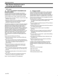
Due to constant research, the information in this manual is subject
to change without notice.
Due to constant research, the information in this manual is subject
to change without notice.
Produced by BARCO NV, June 1998.
All rights reserved.
Produced by BARCO NV, June 1998.
All rights reserved.
Trademarks are the rights of their respective owners.
Trademarks are the rights of their respective owners.
BARCO nv/Projection Systems
Noordlaan 5
B-8520 Kuurne
Belgium
BARCO nv/Projection Systems
Noordlaan 5
B-8520 Kuurne
Belgium
Printed in Belgium
2
Printed in Belgium
R5975765 RCVDS05 020997
2
R5975765 RCVDS05 020997
I. Safety instructions ............................................................................................. 7
I.1 Notice on Safety .................................................................................... 7
I.2. Installation instructions ......................................................................... 7
I.3. On safety .............................................................................................. 9
I.4. On installation ..................................................................................... 10
I.5. On servicing ........................................................................................ 11
I.6. On cleaning ........................................................................................ 11
I.7. On repacking ...................................................................................... 12
II. Introduction ..................................................................................................... 13
II. Introduction ..................................................................................................... 13
III. Input modules ................................................................................................ 15
A. Input module installation. ..................................................................... 16
III. Input modules ................................................................................................ 15
A. Input module installation. ..................................................................... 16
B. Source connection to the RCVDS05. .................................................. 17
B.1. Input module : Video/S-Video. .......................................................... 17
B.2. Input module : RGBS/RGsB analog. ................................................ 19
B.3. Input module : RGB3S/RG3sB analog. ............................................ 20
B.4. Input module : Component Video input ............................................ 21
B.5. Input module : RGBS/RGsB analog for LiDo. .................................. 22
IV. Special modules ............................................................................................ 23
A. Expansion module ................................................................................ 24
B. Communication interface module ........................................................ 25
C. 5 cable output module. ........................................................................ 26
V. Installation ...................................................................................................... 27
A. Power (mains) connection ................................................................... 27
A.1. Power requirements .......................................................................... 27
A.2. Power cord (mains lead) information. ............................................... 27
A.3. Power cord connection ..................................................................... 28
A.4. Switching on ...................................................................................... 28
B. RCVDS05 used as source selector for a BARCO projector. .............. 29
B.1. RCVDS05 to projector communication link. ..................................... 29
B.2. Signal connection. ............................................................................. 29
B.2.1. RCVDS05 to projector. .................................................................. 29
B.2.2. RCVDS05 to audio amplifier. ......................................................... 30
B.3. Using multiple RCVDS05's as source selector for a BARCO
projector. ................................................................................................... 30
B.3.1. Communications link between multiple RCVDS05's. .................... 30
B.3.2. Signal connection between multiple RCVDS05's. ......................... 30
B.4. Optional Remote IR receiver to RCVDS05. ..................................... 31
C. RCVDS05 used as stand alone switcher. ........................................... 33
C.1. Signal connection. ............................................................................ 33
C.1.1. RCVDS05 to display. ..................................................................... 33
C.1.2. RCVDS05 to audio amplifier. ........................................................ 34
C.2. Using multiple RCVDS05's as source selector for a display. .......... 34
C.2.1. Communications link between multiple RCVDS05's. ................... 34
R5975765 RCVDS05 020997
3
C. RCVDS05 used as stand alone switcher. ........................................... 33
C.1. Signal connection. ............................................................................ 33
C.1.1. RCVDS05 to display. ..................................................................... 33
C.1.2. RCVDS05 to audio amplifier. ........................................................ 34
C.2. Using multiple RCVDS05's as source selector for a display. .......... 34
C.2.1. Communications link between multiple RCVDS05's. ................... 34
R5975765 RCVDS05 020997
TABLE OF CONTENTS
TABLE OF CONTENTS
TABLE OF CONTENTS
TABLE OF CONTENTS
3
TABLE OF CONTENTS
4
C.2.2. Signal connection between multiple RCVDS05's. ........................ 34
C.3. Optional Remote IR receiver to RCVDS05. ..................................... 35
C.2.2. Signal connection between multiple RCVDS05's. ........................ 34
C.3. Optional Remote IR receiver to RCVDS05. ..................................... 35
D. RCVDS05 used as high bandwidth signal splitter. .............................. 37
D.1. Use of multiple output modules. ....................................................... 37
D.2. Signal connection. ............................................................................ 37
D.2.1. RCVDS05 to multiple displays ..................................................... 37
D.2.2. RCVDS05 to audio amplifier. ........................................................ 38
D.3. Data communication link between the RCVDS05 and one BARCO ...
projector. ................................................................................................... 38
E. RCVDS05 used with a central computer ............................................. 38
E.1. RCVDS05 connected with a projector .............................................. 38
E.1.1. Installing the link ............................................................................ 38
E.2. RCVDS05 as stand alone switcher. ................................................. 40
E.2.1. Installing the link. ........................................................................... 41
E.2.2. Address setting on the RCVDS05. ................................................ 41
E.3. Signal connection .............................................................................. 41
E.3.1. RCVDS05 to display ...................................................................... 41
E.3.2. RCVDS05 to audio amplifier. ......................................................... 42
E.4. Using multiple RCVDS05's with one central computer. ................... 42
E.4.1. Communication linking between multiple RCVDS05's. ................. 42
E.4.2. Signal connection between multiple RCVDS05's. ......................... 42
E.4.3. Signal connection between multiple RCVDS's and multiple
Displays .................................................................................................... 44
VI. Operating instructions ................................................................................... 46
A. ON/OFF switching ................................................................................ 46
VI. Operating instructions ................................................................................... 46
A. ON/OFF switching ................................................................................ 46
B. "BEEP" indication ................................................................................. 46
B. "BEEP" indication ................................................................................. 46
C. Numbering of the sources. .................................................................. 46
C.1. One RCVDS05. ................................................................................ 47
C.2. Multiple RCVDS05's. ........................................................................ 48
C.3. Multiple RCVDS05's controlled by a central computer. ................... 50
D. Operating the RCVDS05 with the button panel or RCU. .................... 51
D.1. Source selection. .............................................................................. 51
D.1.1. Source selection on a Single RCVDS05. ...................................... 51
D.1.2. Source selection on Multiple RCVDS05's. .................................... 52
D.2. Analog image settings ...................................................................... 53
D.3. Stand by ............................................................................................ 54
D.4. TEXT ................................................................................................. 54
D.5. PAUSE .............................................................................................. 55
D.6. Audio pre-fading. ............................................................................... 55
E. Operating the RCVDS05 with the central computer. ........................... 56
E.1. Communication protocol ................................................................... 56
E.2. The Command codes ....................................................................... 58
R5975765 RCVDS05 020997
TABLE OF CONTENTS
TABLE OF CONTENTS
TABLE OF CONTENTS
4
E. Operating the RCVDS05 with the central computer. ........................... 56
E.1. Communication protocol ................................................................... 56
E.2. The Command codes ....................................................................... 58
R5975765 RCVDS05 020997
TABLE OF CONTENTS
TABLE OF CONTENTS
VII. Error codes ................................................................................................... 66
VIII. Optional decoder ......................................................................................... 68
VIII. Optional decoder ......................................................................................... 68
TABLE OF CONTENTS
TABLE OF CONTENTS
VII. Error codes ................................................................................................... 66
R5975765 RCVDS05 020997
5
R5975765 RCVDS05 020997
5
TABLE OF CONTENTS
6
TABLE OF CONTENTS
TABLE OF CONTENTS
TABLE OF CONTENTS
R5975765 RCVDS05 020997
6
R5975765 RCVDS05 020997
SAFETY INSTRUCTIONS
I. SAFETY INSTRUCTIONS
I. SAFETY INSTRUCTIONS
I.1 Notice on Safety
I.1 Notice on Safety
RCVDS05s are built in accordance with the requirements of the international safety
standards IEC 950 and UL 1950, which are the safety standards of information
technology equipment including electrical business equipment.
RCVDS05s are built in accordance with the requirements of the international safety
standards IEC 950 and UL 1950, which are the safety standards of information
technology equipment including electrical business equipment.
These safety standards impose important requirements on the use of safety critical
components, materials and isolation, in order to protect the user or operator against
risk of electric shock and energy hazard, and having access to live parts.
Safety standards also impose limits to the internal and external temperature rises,
radiation levels, mechanical stability and strength, enclosure construction and
protection against the risk of fire.
Simulated single fault condition testing ensures the safety of the equipment to the
user even when the equipment's normal operation fails.
Simulated single fault condition testing ensures the safety of the equipment to the
user even when the equipment's normal operation fails.
II.2. Installation instructions
II.2. Installation instructions
Before operating the set please read this manual thoroughly, and retain it
for future reference.
Installation and preliminary adjustments should be performed by qualified
BARCO personnel or by authorized BARCO service dealers.
Installation and preliminary adjustments should be performed by qualified
BARCO personnel or by authorized BARCO service dealers.
OWNER’S RECORD
OWNER’S RECORD
The part number and serial number are located at the left side. Record these
numbers in the spaces provided below. Refer to them whenever you call upon your
BARCO dealer regarding this product.
The part number and serial number are located at the left side. Record these
numbers in the spaces provided below. Refer to them whenever you call upon your
BARCO dealer regarding this product.
PART NUMBER:
PART NUMBER:
SER. NUMBER:
SER. NUMBER:
DEALER:
DEALER:
R5975765 RCVDS05 020997
SAFETY INSTRUCTIONS
Before operating the set please read this manual thoroughly, and retain it
for future reference.
7
R5975765 RCVDS05 020997
SAFETY INSTRUCTIONS
SAFETY INSTRUCTIONS
7
SAFETY INSTRUCTIONS
SAFETY INSTRUCTIONS
The lightning flash with an arrowhead within a triangle is
intended to tell the user that parts inside this product may cause
a risk of electrical shock to persons.
The lightning flash with an arrowhead within a triangle is
intended to tell the user that parts inside this product may cause
a risk of electrical shock to persons.
The exclamation point within a triangle is intended to tell the
user that important operating and/or servicing instructions are
included in the technical documentation for this equipment.
The exclamation point within a triangle is intended to tell the
user that important operating and/or servicing instructions are
included in the technical documentation for this equipment.
WARNING
TO PREVENT FIRE OR ELECTRICAL SHOCK HAZARD, DO
NOT EXPOSE THIS RCVDS05 TO RAIN OR MOISTURE
WARNING
TO PREVENT FIRE OR ELECTRICAL SHOCK HAZARD, DO
NOT EXPOSE THIS RCVDS05 TO RAIN OR MOISTURE
FEDERAL COMMUNICATION COMMISSION (FCC STATEMENT)
R5975765 RCVDS05 020997
SAFETY INSTRUCTIONS
SAFETY INSTRUCTIONS
8
This equipment has been tested and found to comply with the limits of a class A
digital device, pursuant to Part 15 of the FCC Rules. These limits are designed to
provide reasonable protection against harmful interference when the equipment is
operated in a commercial environment. This equipment generates, uses and can
radiate radio frequency energy and, if not installed and used in accordance with the
instruction manual, may cause harmful interference to radio communications.
Operation of this equipment in a residential area is likely to cause harmful
interference in which case the user will be required to correct the interference at his
own expense.
FEDERAL COMMUNICATION COMMISSION (FCC STATEMENT)
8
This equipment has been tested and found to comply with the limits of a class A
digital device, pursuant to Part 15 of the FCC Rules. These limits are designed to
provide reasonable protection against harmful interference when the equipment is
operated in a commercial environment. This equipment generates, uses and can
radiate radio frequency energy and, if not installed and used in accordance with the
instruction manual, may cause harmful interference to radio communications.
Operation of this equipment in a residential area is likely to cause harmful
interference in which case the user will be required to correct the interference at his
own expense.
R5975765 RCVDS05 020997
SAFETY INSTRUCTIONS
SAFETY INSTRUCTIONS
* All the safety and operating instructions should be read before using this unit.
* All the safety and operating instructions should be read before using this unit.
* The safety and operating instructions manual should be retained for future
reference.
* The safety and operating instructions manual should be retained for future
reference.
* All warnings on the projector and in the documentation manuals should be adhered
to.
* All warnings on the projector and in the documentation manuals should be adhered
to.
* All instructions for operating and use of this equipment must be followed precisely.
* All instructions for operating and use of this equipment must be followed precisely.
I.3. On safety
I.3. On safety
* This product should be operated from an AC power source.
The power input is auto-ranging from 100 to 240 VAC
This RCVDS05 may be connected to an IT-power system.
* This product should be operated from an AC power source.
The power input is auto-ranging from 100 to 240 VAC
This RCVDS05 may be connected to an IT-power system.
* This product is equipped with a 3-wire grounding plug, a plug having a third
(grounding) pin. This plug will only fit into a grounding-type power outlet. This is a
safety feature. If you are unable to insert the plug into the outlet, contact your
electrician to replace your obsolete outlet. Do not defeat the purpose of the groundingtype plug.
WARNING FOR THE CUSTOMERS: THIS APPARATUS MUST BE GROUNDED
(EARTHED) via the supplied 3 conductor AC power cable.
(If the supplied power cable is not the correct one, consult your dealer.)
WARNING FOR THE CUSTOMERS: THIS APPARATUS MUST BE GROUNDED
(EARTHED) via the supplied 3 conductor AC power cable.
(If the supplied power cable is not the correct one, consult your dealer.)
A. Mains lead (AC Power cord) with CEE 7
plug:
A. Mains lead (AC Power cord) with CEE 7
plug:
The colors of the mains lead are colored in
accordance with the following code:
The colors of the mains lead are colored in
accordance with the following code:
R5975765 RCVDS05 020997
9
SAFETY INSTRUCTIONS
Green-and-yellow: Earth (safety earth)
Blue:
Neutral
Brown:
Line (Live)
SAFETY INSTRUCTIONS
Green-and-yellow: Earth (safety earth)
Blue:
Neutral
Brown:
Line (Live)
R5975765 RCVDS05 020997
9
SAFETY INSTRUCTIONS
SAFETY INSTRUCTIONS
B. Power cord with ANSI 73.11 plug:
B. Power cord with ANSI 73.11 plug:
The wires of the power cord are colored in
accordance with the following code.
The wires of the power cord are colored in
accordance with the following code.
Green/yellow: ground
White:
neutral
Black:
line (live)
* Do not allow anything to rest on the power cord. Do not locate this product where
persons will walk on the cord.
* Do not allow anything to rest on the power cord. Do not locate this product where
persons will walk on the cord.
To disconnect the cord, pull it out by the plug. Never pull the cord itself.
To disconnect the cord, pull it out by the plug. Never pull the cord itself.
* If an extension cord is used with this product, make sure that the total of the ampere
ratings on the products plugged into the extension cord does not exceed the
extension cord ampere rating. Also make sure that the total of all products plugged
into the wall outlet does not exceed 15 amperes.
* If an extension cord is used with this product, make sure that the total of the ampere
ratings on the products plugged into the extension cord does not exceed the
extension cord ampere rating. Also make sure that the total of all products plugged
into the wall outlet does not exceed 15 amperes.
* Never push objects of any kind into this product through cabinet slots as they may
touch dangerous voltage points or short out parts that could result in a risk of fire
or electrical shock.
* Never push objects of any kind into this product through cabinet slots as they may
touch dangerous voltage points or short out parts that could result in a risk of fire
or electrical shock.
Never spill liquid of any kind on the product. Should any liquid or solid object fall into
the cabinet, unplug the set and have it checked by qualified service personnel before
resuming operations.
Never spill liquid of any kind on the product. Should any liquid or solid object fall into
the cabinet, unplug the set and have it checked by qualified service personnel before
resuming operations.
* Lightning - For added protection for this video product during a lightning storm, or
when it is left unattended and unused for long periods of time, unplug it from the wall
outlet. This will prevent damage to the RCVDS05 due to lightning and AC powerline surges.
* Lightning - For added protection for this video product during a lightning storm, or
when it is left unattended and unused for long periods of time, unplug it from the wall
outlet. This will prevent damage to the RCVDS05 due to lightning and AC powerline surges.
I.4. On installation
I.4. On installation
* Do not place this set on an unstable cart, stand, or table. The set may fall, causing
serious damage to it.
* Do not use this set near water.
* Slots and openings in the cabinet and the back or bottom are provided for
ventilation; to ensure reliable operation of the RCVDS05 and to protect it from
overheating, these openings must not be blocked or covered. The openings should
never be blocked by placing the product on a bed, sofa, rug, or other similar surface.
R5975765 RCVDS05 020997
SAFETY INSTRUCTIONS
SAFETY INSTRUCTIONS
10
Green/yellow: ground
White:
neutral
Black:
line (live)
10
* Do not place this set on an unstable cart, stand, or table. The set may fall, causing
serious damage to it.
* Do not use this set near water.
* Slots and openings in the cabinet and the back or bottom are provided for
ventilation; to ensure reliable operation of the RCVDS05 and to protect it from
overheating, these openings must not be blocked or covered. The openings should
never be blocked by placing the product on a bed, sofa, rug, or other similar surface.
R5975765 RCVDS05 020997
SAFETY INSTRUCTIONS
This product should never be placed near or over a radiator or heat register. This
switcher should not be placed in a built-in installation or enclosure unless proper
ventilation is provided.
I.5. On servicing
I.5. On servicing
Do not attempt to service this RCVDS05 yourself, as opening or removing covers
may expose you to dangerous voltage potentials and risk of electric shock!
Refer all servicing to qualified service personnel.
Do not attempt to service this RCVDS05 yourself, as opening or removing covers
may expose you to dangerous voltage potentials and risk of electric shock!
Refer all servicing to qualified service personnel.
Unplug this product from the wall outlet and refer servicing to qualified
service personnel under the following conditions:
Unplug this product from the wall outlet and refer servicing to qualified
service personnel under the following conditions:
a. When the power cord or plug is damaged or frayed.
a. When the power cord or plug is damaged or frayed.
b. If liquid has been spilled into the RCVDS05.
b. If liquid has been spilled into the RCVDS05.
c.If the product has been exposed to rain or water.
c.If the product has been exposed to rain or water.
d. If the product does not operate normally when the operating instructions are
followed. Note :
Adjust only those controls that are covered by the operating instructions since
improper adjustment of the other controls may result in damage and will often
require extensive work by a qualified technician to restore the product to
normal operation.
e. If the product has been dropped or the cabinet has been damaged.
e. If the product has been dropped or the cabinet has been damaged.
f. If the product exibits a distinct change in performance, indicating a need for
service.
f. If the product exibits a distinct change in performance, indicating a need for
service.
Replacement parts - When replacement parts are required, be sure the service
technician has used original BARCO replacement parts or authorized replacement
parts which have the same characteristics as the BARCO original part. Unauthorized substitutions may result in degraded performance and reliability, fire, electric
shock or other hazards. Unauthorized substitutions may void warranty.
Safety check - Upon completion of any service or repairs to this switcher, ask the
service technician to perform safety checks to determine that the switcher is in
proper operating condition.
Safety check - Upon completion of any service or repairs to this switcher, ask the
service technician to perform safety checks to determine that the switcher is in
proper operating condition.
I.6. On cleaning
Unplug this product from the wall outlet before cleaning. Do not use liquid
cleaners or aerosol cleaners. Use a damp cloth for cleaning.
- To keep the cabinet looking brand-new, periodically clean it with a soft cloth.
Stubborn stains may be removed with a cloth lightly dampened with mild detergent
R5975765 RCVDS05 020997
SAFETY INSTRUCTIONS
This product should never be placed near or over a radiator or heat register. This
switcher should not be placed in a built-in installation or enclosure unless proper
ventilation is provided.
11
I.6. On cleaning
Unplug this product from the wall outlet before cleaning. Do not use liquid
cleaners or aerosol cleaners. Use a damp cloth for cleaning.
- To keep the cabinet looking brand-new, periodically clean it with a soft cloth.
Stubborn stains may be removed with a cloth lightly dampened with mild detergent
R5975765 RCVDS05 020997
SAFETY INSTRUCTIONS
SAFETY INSTRUCTIONS
11
SAFETY INSTRUCTIONS
SAFETY INSTRUCTIONS
solution. Never use strong solvents, such as thinner or benzine, or abrasive
cleaners, since these will damage the cabinet.
solution. Never use strong solvents, such as thinner or benzine, or abrasive
cleaners, since these will damage the cabinet.
I.7. On repacking
I.7. On repacking
Save the original shipping carton and packing material; they will come in handy if
you ever have to ship your set. For maximum protection, repack your set as it was
originally packed at the factory.
Save the original shipping carton and packing material; they will come in handy if
you ever have to ship your set. For maximum protection, repack your set as it was
originally packed at the factory.
SAFETY INSTRUCTIONS
SAFETY INSTRUCTIONS
12
R5975765 RCVDS05 020997
12
R5975765 RCVDS05 020997
INTRODUCTION
INTRODUCTION
II. INTRODUCTION
II. INTRODUCTION
The RCVDS05 offers the possibility to connect a wide range of video, data and
graphics sources to one or more projectors or other displays.
Its modular input design makes it possible to easily adapt the switcher to the user's
input requirements. This RCVDS05 can be equipped with up to 10 input modules.
The following input modules are available as option :
The following input modules are available as option :
- RGB analog with standard sync input module
- RGB analog with Tri-level sync input module
- Video/S-video input module
98 27900
- Component video (R-Y, Y, B-Y) input module
98 27910
98 27920
98 27930
98 27910
98 27920
98 27930
When using the optional expansion module (98 28000), it is possible to connect
several source switchers in series, which gives the opportunity to connect up to 90
sources simultaneously to one projector or display.
Additional output modules can be added which makes it possible to connect up to four
displays to one RCVDS05. It reconfigures the unit as a high bandwidth signal splitter.
With the additional communication module (98 28010), it is possible to control up to
16 RCVDS05 switchers (in stand alone use) from one central computer.
With the additional communication module (98 28010), it is possible to control up to
16 RCVDS05 switchers (in stand alone use) from one central computer.
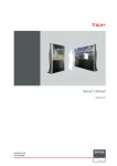
Principal connection diagrams.
Principal connection diagrams.
1. with BARCO projector.
1. with BARCO projector.
Communication link
Composite Video
Composite Video
RGB Analog
RGB Analog
R5975765 RCVDS05 020997
Composite Video
RGB Analog
RGB Analog
RCVDS05
INTRODUCTION
RCVDS05
RGB Analog
Communication link
Composite Video
13
RGB Analog
R5975765 RCVDS05 020997
INTRODUCTION
- RGB analog with standard sync input module
- RGB analog with Tri-level sync input module
- Video/S-video input module
98 27900
- Component video (R-Y, Y, B-Y) input module
13
INTRODUCTION
INTRODUCTION
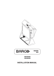
2. As splitter.
2. As splitter.
Communication link
Composite Video
Composite Video
RGB Analog
RGB Analog
Communication link
Composite Video
Composite Video
RGB Analog
RGB Analog
RCVDS05
RCVDS05
Comp.
Video
RGB Analog
Comp.
Video
RGB Analog
RGB Analog
RGB Analog
Comp.
Video
RGB Analog
Comp.
Video
RGB Analog
3. As stand alone system switcher.
3. As stand alone system switcher.
Composite Video
Composite Video
RCVDS05
RCVDS05
RGB Analog
RGB Analog
RGB Analog
RGB Analog
Comp. Video
Comp. Video
RS232
RGB Analog
Optional
control via
PC
R5975765 RCVDS05 020997
RGB Analog
INTRODUCTION
INTRODUCTION
14
RS232
14
Optional
control via
PC
R5975765 RCVDS05 020997
INPUT MODULES
III. INPUT MODULES
III. INPUT MODULES
As the RCVDS05 works as an interface between the different input sources and the
display (projector or monitor) it connects the following sources through to the output
module or modules (max 4):
- composite video
- S-video
- RGB analog with standard sync
- RGB analog with Tri-level sync
- Component video
Four input modules are available for the RCVDS05
- Video/S-video input module
- RGB analog input module with standard sync
- RGB analog input module with Tri-level sync
- Component video input module
- RGB analog input module with standard sync for LiDo (Line Doubling)
Four input modules are available for the RCVDS05
- Video/S-video input module
- RGB analog input module with standard sync
- RGB analog input module with Tri-level sync
- Component video input module
- RGB analog input module with standard sync for LiDo (Line Doubling)
(1)
98 27910
(2)
98 27920
(3)
98 27930
(4)
98 27900
(5)
An independent audio connection is provided on the backplane of the RCVDS05 for
each input slot. (The Video/S-Video module has a separate audio input for S-Video)
Use slots 1 to 10 to insert the input modules (see Input module installation).
R5975765 RCVDS05 020997
(1)
INPUT MODULES
98 27900
15
98 27910
(2)
98 27920
(3)
98 27930
(4)
(5)
An independent audio connection is provided on the backplane of the RCVDS05 for
each input slot. (The Video/S-Video module has a separate audio input for S-Video)
Use slots 1 to 10 to insert the input modules (see Input module installation).
R5975765 RCVDS05 020997
INPUT MODULES
INPUT MODULES
15
INPUT MODULES
INPUT MODULES
A. Input module installation.
Up to 10 input modules can be inserted in any order in the RCVDS05.
Up to 10 input modules can be inserted in any order in the RCVDS05.
Install the input modules in the RCVDS05 as follows :
Install the input modules in the RCVDS05 as follows :
1. Power down the RCVDS05 and disconnect the power cord from the wall outlet.
1. Power down the RCVDS05 and disconnect the power cord from the wall outlet.
2. Slide the input module into a free slot in the board rack (rear of the RCVDS05).
Insure that the module is seated correctly in the guide grooves A.
2. Slide the input module into a free slot in the board rack (rear of the RCVDS05).
Insure that the module is seated correctly in the guide grooves A.
3. Press the face of the input module until the module plug seats in the backplane
connector of the RCVDS05.
3. Press the face of the input module until the module plug seats in the backplane
connector of the RCVDS05.
4. Secure the input module by tightening the retaining screws B on top and bottom.
4. Secure the input module by tightening the retaining screws B on top and bottom.
%
%
$
INPUT MODULES
INPUT MODULES
16
A. Input module installation.
R5975765 RCVDS05 020997
16
$
R5975765 RCVDS05 020997
INPUT MODULES
INPUT MODULES
B. Source connection to the RCVDS05.
B. Source connection to the RCVDS05.
B.1. Input module : Video/S-Video.
B.1. Input module : Video/S-Video.
Order number : 98 27900
Order number : 98 27900
Signal connection : video composite, S-video and audio.
Signal connection : video composite, S-video and audio.
Composite Video : 1xBNC 1.0Vpp ± 3 dB
The audio signal, corresponding to the composite video signal must be connected
to the audio connector on the base plate just below the slot where the module is
inserted.
2 x RCA (cinch) 1 Vpp ± 3dB
Composite Video : 1xBNC 1.0Vpp ± 3 dB
The audio signal, corresponding to the composite video signal must be connected
to the audio connector on the base plate just below the slot where the module is
inserted.
2 x RCA (cinch) 1 Vpp ± 3dB
S-Video : (luma/chroma) 1x4 pins plug (mini DIN)
pin configuration
1 ground luminance
2 ground chrominance
3 luminance 1.0 Vpp ± 3 dB
4 chrominance 282 mVpp ± 3dB
The audio signal, corresponding to the S-Video signal must be directly connected
to the audio connectors on the input module.
2 x RCA (cinch) 1Vpp ± 3dB
Both sources on this input module are simultaniously available.
Both sources on this input module are simultaniously available.
The Video/S-Video input module can be inserted in any input between 1 and 10.
The Video/S-Video input module can be inserted in any input between 1 and 10.
S-Video in
S-Video in
Audio left in
Audio left in
Audio for
S-Video source
Audio for
S-Video source
Composite Video in
The audio signal for the Video source has to be
connected to the audio input just below the Video input slot.
R5975765 RCVDS05 020997
98 27900
17
Composite Video in
The audio signal for the Video source has to be
connected to the audio input just below the Video input slot.
R5975765 RCVDS05 020997
98 27900
INPUT MODULES
Audio right in
INPUT MODULES
Audio right in
17
INPUT MODULES
INPUT MODULES
Straps on module level :
Straps on module level :
Floating or non-floating input.
Floating or non-floating input.
Video input :
J11 : strap "yes" : non floating strap "no" : floating
Video input :
J11 : strap "yes" : non floating strap "no" : floating
S-Video input :
J12 : strap "yes" : non floating strap "no" : floating
J13 : strap "yes" : non floating strap "no" : floating
S-Video input :
J12 : strap "yes" : non floating strap "no" : floating
J13 : strap "yes" : non floating strap "no" : floating
Factory preset : strap on, input non floating.
Factory preset : strap on, input non floating.
-
-
-
-
-
-
) O R D W L Q J R U Q R Q I O R D W L Q J L Q S X W
Non-Floating
) O R D W L Q J R U Q R Q I O R D W L Q J L Q S X W
Non-Floating
INPUT MODULES
INPUT MODULES
18
Floating
R5975765 RCVDS05 020997
18
Floating
R5975765 RCVDS05 020997
INPUT MODULES
INPUT MODULES
B.2. Input module : RGBS/RGsB analog.
B.2. Input module : RGBS/RGsB analog.
Order number : 98 27910
Order number : 98 27910
RGBS/RGsB analog : 5 x BNC
Red : 0.7 Vpp ± 3 dB
Blue : 0.7 Vpp ± 3 dB
Green : 0.7 Vpp ± 3 dB
1 Vpp ± 3 dB if sync on green
Vert. sync : 1 Vpp to 4 Vpp ± 3 dB
Hor. sync / Composite sync :
1 Vpp to 4 Vpp ± 3 dB
RGBS/RGsB analog : 5 x BNC
Red : 0.7 Vpp ± 3 dB
Blue : 0.7 Vpp ± 3 dB
Green : 0.7 Vpp ± 3 dB
1 Vpp ± 3 dB if sync on green
Vert. sync : 1 Vpp to 4 Vpp ± 3 dB
Hor. sync / Composite sync :
1 Vpp to 4 Vpp ± 3 dB
Red
Green
All input signals are always 75 ohm terminated,
even in the "not selected" mode.
The audio signal corresponding
to the source has to be connected
to the audio input just below the
RGBS analog input slot.
Red
Green
All input signals are always 75 ohm terminated,
even in the "not selected" mode.
Blue
The audio signal corresponding
to the source has to be connected
to the audio input just below the
RGBS analog input slot.
Horizontal or composite
sync
Horizontal or composite
sync
Vertical sync
Straps on module level :
Floating or non-floating input.
Red : J3 : strap "yes" : non floating
Green : J4 : strap "yes" : non floating
Blue : J5 : strap "yes" : non floating
H/C : J6 : strap "yes" : non floating
V:
J7 : strap "yes" : non floating
strap "no" : floating
strap "no" : floating
strap "no" : floating
strap "no" : floating
strap "no" : floating
Vertical sync
Straps on module level :
Floating or non-floating input.
Red : J3 : strap "yes" : non floating
Green : J4 : strap "yes" : non floating
Blue : J5 : strap "yes" : non floating
H/C : J6 : strap "yes" : non floating
V:
J7 : strap "yes" : non floating
98 27910
strap "no" : floating
strap "no" : floating
strap "no" : floating
strap "no" : floating
strap "no" : floating
Factory preset : strap "yes", non floating input
Sync selection.
J8 : see drawing
Sync selection.
J8 : see drawing
Factory preset : separate sync.
Factory preset : separate sync.
19
98 27910
INPUT MODULES
INPUT MODULES
Factory preset : strap "yes", non floating input
R5975765 RCVDS05 020997
Blue
R5975765 RCVDS05 020997
19
INPUT MODULES
INPUT MODULES
-
6
-
-
-
-
< 1 & 6 ( / ( & 7 ,2 1
6 H S D U D W H V \ Q F
-
-
-
6
< 1 & 6 ( / ( & 7 ,2 1
-
-
-
6 \ Q F R Q J U H H Q
-
Non-Floating
Non-Floating
) OR D W LQ J R U Q R Q I OR D W LQ J LQ S X W
) OR D W LQ J R U Q R Q I OR D W LQ J LQ S X W
Floating
INPUT MODULES
INPUT MODULES
Floating
20
6 H S D U D W H V \ Q F
6 \ Q F R Q J U H H Q
R5975765 RCVDS05 020997
20
R5975765 RCVDS05 020997
INPUT MODULES
INPUT MODULES
B.3. Input module : RGB3S/RG3sB analog.
B.3. Input module : RGB3S/RG3sB analog.
Order number : 98 27920
Order number : 98 27920
RGB3S/RG3sB analog : 5 x BNC
Red : 0.7 Vpp ± 3 dB
Blue : 0.7 Vpp ± 3 dB
Green : 0.7 Vpp ± 3 dB
1 Vpp ± 3 dB if Tri-level sync on green
Vert. Tri-level sync : 1 Vpp to 4 Vpp ± 3 dB
Hor. Tri-level sync / Composite Tri-level sync:
1 Vpp to 4 Vpp ± 3 dB
RGB3S/RG3sB analog : 5 x BNC
Red : 0.7 Vpp ± 3 dB
Blue : 0.7 Vpp ± 3 dB
Green : 0.7 Vpp ± 3 dB
1 Vpp ± 3 dB if Tri-level sync on green
Vert. Tri-level sync : 1 Vpp to 4 Vpp ± 3 dB
Hor. Tri-level sync / Composite Tri-level sync:
1 Vpp to 4 Vpp ± 3 dB
All input signals are always 75 ohm
terminated, even in the "not selected"
mode.
The corresponding audio signal for
this source has to be connected to
the audio input just below the RGB3S
analog input slot.
Red
Green
All input signals are always 75 ohm
terminated, even in the "not selected"
mode.
Blue
Horizontal or composite
3 level sync
The corresponding audio signal for
this source has to be connected to
the audio input just below the RGB3S
analog input slot.
Vertical 3 level sync
Red
Green
Blue
Horizontal or composite
3 level sync
Vertical 3 level sync
98 27920
98 27920
Straps on module level :(see photo on
analog')
Floating or non-floating input.
Red : J3 : strap "yes" : non floating
Green : J4 : strap "yes" : non floating
Blue : J5 : strap "yes" : non floating
H/C : J6 : strap "yes" : non floating
V:
J7 : strap "yes" : non floating
Straps on module level :(see photo on
analog')
Floating or non-floating input.
Red : J3 : strap "yes" : non floating
Green : J4 : strap "yes" : non floating
Blue : J5 : strap "yes" : non floating
H/C : J6 : strap "yes" : non floating
V:
J7 : strap "yes" : non floating
page 20 'B.2. Input module : RGBS/RGsB
strap "no" : floating
strap "no" : floating
strap "no" : floating
strap "no" : floating
strap "no" : floating
page 20 'B.2. Input module : RGBS/RGsB
strap "no" : floating
strap "no" : floating
strap "no" : floating
strap "no" : floating
strap "no" : floating
Factory preset : strap "yes", non floating input
Factory preset : strap "yes", non floating input
Sync selection.
J8 : separate sync or sync on green.
Sync selection.
J8 : separate sync or sync on green.
Factory preset : separate sync.
Factory preset : separate sync.
INPUT MODULES
INPUT MODULES
R5975765 RCVDS05 020997
21
R5975765 RCVDS05 020997
21
INPUT MODULES
INPUT MODULES
B.4. Input module : Component Video input
B.4. Input module : Component Video input
Order number : 98 27930
Order number : 98 27930
Component video : 4 x BNC
R-Y : 0.7 Vpp ± 3 dB
B-Y : 0.7 Vpp ± 3 dB
Y:
0.7 Vpp ± 3 dB
1 Vpp ± 3 dB if Tri-level sync on green
Composite sync : 1 Vpp to 4 Vpp ± 3 dB
Component video : 4 x BNC
R-Y : 0.7 Vpp ± 3 dB
B-Y : 0.7 Vpp ± 3 dB
Y:
0.7 Vpp ± 3 dB
1 Vpp ± 3 dB if Tri-level sync on green
Composite sync : 1 Vpp to 4 Vpp ± 3 dB
Red - Luma
Luma
Luma
All input signals are always 75 ohm terminated,
even the module is "not selected".
All input signals are always 75 ohm terminated,
even the module is "not selected".
Blue - Luma
The corresponding audio signal for this source has
to be connected to the audio input just below the
component video input slot.
Blue - Luma
The corresponding audio signal for this source has
to be connected to the audio input just below the
component video input slot.
Sync
Straps on module level :
Floating or non-floating input.
R-Y : J3 : strap "yes" : non floating
Y:
J4 : strap "yes" : non floating
B-Y : J5 : strap "yes" : non floating
C:
J6 : strap "yes" : non floating
Sync
Straps on module level :
strap "no" : floating
strap "no" : floating
strap "no" : floating
strap "no" : floating
Floating or non-floating input.
R-Y : J3 : strap "yes" : non floating
Y:
J4 : strap "yes" : non floating
B-Y : J5 : strap "yes" : non floating
C:
J6 : strap "yes" : non floating
98 27930
strap "no" : floating
strap "no" : floating
strap "no" : floating
strap "no" : floating
Factory preset : strap "yes", non floating input
Factory preset : strap "yes", non floating input
Sync selection.
J8 :
strap "no" : separate sync
strap "yes" : sync on Y.
Sync selection.
J8 :
strap "no" : separate sync
strap "yes" : sync on Y.
J9 :
strap "yes" : Tri-level sync
strap "no" : normal sync.
J9 :
strap "yes" : Tri-level sync
strap "no" : normal sync.
Factory preset :
separate sync and
normal sync.
Factory preset :
separate sync and
normal sync.
98 27930
INPUT MODULES
INPUT MODULES
22
Red - Luma
R5975765 RCVDS05 020997
22
R5975765 RCVDS05 020997
INPUT MODULES
INPUT MODULES
)ORDWLQJRUQRQIORDWLQJLQSXW
)ORDWLQJRUQRQIORDWLQJLQSXW
Non-Floating
Non-Floating
Floating
-
-
-
-
-
-
-
-
-
-
6\QFVHOHFWLRQ
6 H S D UD WH V \ Q F
1 R UP D O6 \ Q F
R5975765 RCVDS05 020997
-
6 \ Q F R Q <
7ULOHYHO6\QF
INPUT MODULES
-
23
-
-
-
-
6\QFVHOHFWLRQ
6 H S D UD WH V \ Q F
1 R UP D O6 \ Q F
R5975765 RCVDS05 020997
6 \ Q F R Q <
7ULOHYHO6\QF
INPUT MODULES
Floating
23
INPUT MODULES
INPUT MODULES
B.5. Input module : RGBS/RGsB analog for Line Doubling*
B.5. Input module : RGBS/RGsB analog for Line Doubling*
Order number : R9828410
Order number : R9828410
RGBS/RGsB analog : 4 x BNC
Red : 0.7 Vpp ± 3 dB
Blue : 0.7 Vpp ± 3 dB
Green : 0.7 Vpp ± 3 dB
1 Vpp ± 3 dB if sync on green
Comp. Sync : 0.3 Vpp to 4 Vpp ± 3 dB
RGBS/RGsB analog : 4 x BNC
Red : 0.7 Vpp ± 3 dB
Blue : 0.7 Vpp ± 3 dB
Green : 0.7 Vpp ± 3 dB
1 Vpp ± 3 dB if sync on green
Comp. Sync : 0.3 Vpp to 4 Vpp ± 3 dB
Polarity of the input signals
R, G and B signal: positive signal
Sync Signals: negative Composite signal
Red
Green/Gs
Polarity of the input signals
R, G and B signal: positive signal
Sync Signals: negative Composite signal
Blue
Blue
All input signals are always 75 ohm terminated,
even in the "not selected" mode.
Composite Sync
The audio signal corresponding to the source has
to be connected to the audio input just below the
INPUT FOR LIDO slot.
Strap on module level:
Strap on module level:
Insertion or non of a strap on the module determines the following Sync mode:
Insertion or non of a strap on the module determines the following Sync mode:
No strap = Automatic detection of Separate or Sync on Green.
Strap in position RGBS: separate Sync.
Strap in the position RGsB: Sync. on Green.
RGBS
12
12
12
12
RGBS
12
12
12
12
RGsB
RGsB
12
12
12
12
12
INPUT MODULES
INPUT MODULES
Green/Gs
All input signals are always 75 ohm terminated,
even in the "not selected" mode.
Composite Sync
The audio signal corresponding to the source has
to be connected to the audio input just below the
INPUT FOR LIDO slot.
No strap = Automatic detection of Separate or Sync on Green.
Strap in position RGBS: separate Sync.
Strap in the position RGsB: Sync. on Green.
24
Red
*Line Doubling if RCVDS05 is equipped with a line Doubler unit
R5975765 RCVDS05 020997
24
12
12
12
12
*Line Doubling if RCVDS05 is equipped with a line Doubler unit
R5975765 RCVDS05 020997
SPECIAL MODULES
SPECIAL MODULES
IV. SPECIAL MODULES
IV. SPECIAL MODULES
A. Expansion module
A. Expansion module
Order number : 98 28000
Order number : 98 28000
To allow more inputs than a RCVDS05 can normally accept, several RCVDS05's can
be connected in series to allow swicthing of up to 90 sources.
To allow more inputs than a RCVDS05 can normally accept, several RCVDS05's can
be connected in series to allow swicthing of up to 90 sources.
Signal connection : 5 x BNC
Signal connection : 5 x BNC
The signal connection between RCVDS05 n and RCVDS05 (n+1) is established only
by 5 coaxial cables. Video, S-video, RGB analog and component video signals are
all transferred through these 5 cables (see installation, multiple RCVDS05).
The signal connection between RCVDS05 n and RCVDS05 (n+1) is established only
by 5 coaxial cables. Video, S-video, RGB analog and component video signals are
all transferred through these 5 cables (see installation, multiple RCVDS05).
Output signals
from next
RCVDS05
Red
Red
Green
Green
Output signals
from next
RCVDS05
Blue
Horizontal /
composite sync
Horizontal /
composite sync
Vertical sync
Vertical sync
98 28000
98 28000
25
SPECIAL MODULES
SPECIAL MODULES
R5975765 RCVDS05 020997
Blue
R5975765 RCVDS05 020997
25
SPECIAL MODULES
SPECIAL MODULES
B. COMMUNICATION INTERFACE MODULE
B. COMMUNICATION INTERFACE MODULE
order number : 98 28010
order number : 98 28010
When the RCVDS05's are linked or the optional IR remote receiver will be used or your
RCVDS05 will be controlled by a central computer, a communication module must be
installed in the slot near the output module.
For typical configurations see Installation.
When the RCVDS05's are linked or the optional IR remote receiver will be used or your
RCVDS05 will be controlled by a central computer, a communication module must be
installed in the slot near the output module.
For typical configurations see Installation.
Connections :
Connections :
* The female D9 Sub-D connector, indicated as "to host" must be connected to
the communication port RS232 on the computer.
* The female D9 Sub-D connector, indicated as "to host" must be connected to
the communication port RS232 on the computer.
* the male D9 Sub-D connector, indicated as "to next device" must be connected to
:
- to next RCVDS05 in the link (see installation)
or
- the optional IR remote receiver unit.
* the male D9 Sub-D connector, indicated as "to next device" must be connected to
:
- to next RCVDS05 in the link (see installation)
or
- the optional IR remote receiver unit.
From
central computer
From
central computer
Mode switch
"BARCO" or "RS232"
Mode switch
"BARCO" or "RS232"
To next RCVDS05
or
IR receiver unit
To next RCVDS05
or
IR receiver unit
98 28010
SPECIAL MODULES
SPECIAL MODULES
98 28010
26
R5975765 RCVDS05 020997
26
R5975765 RCVDS05 020997
SPECIAL MODULES
SPECIAL MODULES
Switch function RS232 - BARCO
Switch function RS232 - BARCO
a) RCVDS05 used with BARCO projector : switch in position "BARCO".
a) RCVDS05 used with BARCO projector : switch in position "BARCO".
b) RCVDS05 used as stand alone unit : switch in position "BARCO".
b) RCVDS05 used as stand alone unit : switch in position "BARCO".
c) RCVDS05 controlled by a central computer : switch in position "RS232"
c) RCVDS05 controlled by a central computer : switch in position "RS232"
Address setting on module level.
Address setting on module level.
This address setting is only necessary in stand alone use and during the control with
a central computer.
Addresses between 0 and 15 are possible.
Address setting is a hardware set up on the communication interface module.
Therefore 4 DIP switches are provided on the module.
Each DIP switch has its own decimal value. The sum of the values associated with
those DIP switches gives the address.
Switch
1
2
3
4
Switch
1
2
3
4
Value
1
2
4
8
Example : address 7
Value
1
2
4
8
Example : address 7
DIP switch
1 2
3
setting
1 1
1
Summary : 1x1 + 1x2 + 1x4 + 0x8 = 7
4
0
DIP switch
1 2
3
setting
1 1
1
Summary : 1x1 + 1x2 + 1x4 + 0x8 = 7
21 21 2)) 2)) 27
SPECIAL MODULES
SPECIAL MODULES
R5975765 RCVDS05 020997
4
0
R5975765 RCVDS05 020997
27
SPECIAL MODULES
SPECIAL MODULES
C. 5 cable output module.
C. 5 cable output module.
Order number : 98 27950
All signals, Video, S-Video, RGB analog as well as Component video are transferred
via 5 output BNC's.
This module is designed to be used as an output module in linked RCVDS's (as
replacement for the standard output module), except in the first RCVDS05.
Order number : 98 27950
All signals, Video, S-Video, RGB analog as well as Component video are transferred
via 5 output BNC's.
This module is designed to be used as an output module in linked RCVDS's (as
replacement for the standard output module), except in the first RCVDS05.
Red
Red
Green
Green
Blue
Blue
Horizontal /
composite sync
Horizontal /
composite sync
Vertical sync
Vertical sync
28
98 27950
SPECIAL MODULES
SPECIAL MODULES
98 27950
R5975765 RCVDS05 020997
28
R5975765 RCVDS05 020997
INSTALLATION
INSTALLATION
V. INSTALLATION
V. INSTALLATION
A. Power (mains) connection
A. Power (mains) connection
A.1. Power requirements
A.1. Power requirements
The power input is auto-ranging from 100 to 240 VAC
100 - 240 V 0.8 - 0.4 A 60 - 50 Hz 50 Watt
The power input is auto-ranging from 100 to 240 VAC
100 - 240 V 0.8 - 0.4 A 60 - 50 Hz 50 Watt
A.2. Power cord (mains lead) information.
A.2. Power cord (mains lead) information.
If it becomes necessary to use a power cord with another plug standard as the one
delivered with the RCVDS05, contact a qualified service technician.
If it becomes necessary to use a power cord with another plug standard as the one
delivered with the RCVDS05, contact a qualified service technician.
a. Power cord (mains lead) with CEE7 plug :
a. Power cord (mains lead) with CEE7 plug :
The wires of the delivered mains lead (power cord) are colored in accordance with the
following code :
The wires of the delivered mains lead (power cord) are colored in accordance with the
following code :
Green and yellow : ground (earth)
Blue : neutral
Brown : live
Green and yellow : ground (earth)
Blue : neutral
Brown : live
b. Power cord with an ANSI 73.11 plug.
b. Power cord with an ANSI 73.11 plug.
The wires of the delivered mains lead (power cord) are colored in accordance with the
following code :
The wires of the delivered mains lead (power cord) are colored in accordance with the
following code :
Green and yellow : ground (earth)
White : neutral
Black : live
Green and yellow : ground (earth)
White : neutral
Black : live
INSTALLATION
INSTALLATION
R5975765 RCVDS05 020997
29
R5975765 RCVDS05 020997
29
INSTALLATION
INSTALLATION
A.3. Power cord connection
A.3. Power cord connection
Plug the male end of the power cord into an available power outlet.
Plug the male end of the power cord into an available power outlet.
A.4. Switching on
A.4. Switching on
The RCVDS05 is switched ON and OFF using the power (mains) switch ON/OFF on
the front of the RCVDS05.
The RCVDS05 is switched ON and OFF using the power (mains) switch ON/OFF on
the front of the RCVDS05.
pressed : ON
not pressed : OFF
pressed : ON
not pressed : OFF
5(027(&21752//('9,'(2'$7$6(/(&725
67%< 3$86( 7(;7
212))
$8',2
3 ()$', *
6+$531 +8( 6$7 %5,*+71&2175
5&9'6
5(027(&21752//('9,'(2'$7$6(/(&725
67%< 3$86( 7(;7
,5
6(/(&7(',1387
212))
6+$531 +8( 6$7 %5,*+71&2175
,5
6(/(&7(',1387
INSTALLATION
INSTALLATION
30
$8',2
3 ()$', *
5&9'6
R5975765 RCVDS05 020997
30
R5975765 RCVDS05 020997
INSTALLATION
INSTALLATION
B. RCVDS05 USED AS SOURCE SELECTOR FOR A BARCO
PROJECTOR.
B. RCVDS05 USED AS SOURCE SELECTOR FOR A BARCO
PROJECTOR.
B.1. RCVDS05 to PROJECTOR communication link.
B.1. RCVDS05 to PROJECTOR communication link.
Plug the male D9 connector of a communication cable into the female D9 connector
labelled "to projector" on the back plane of the RCVDS05.
Plug the female D9 connector of the other end of the communication cable into the
male connector labelled "com port (800 peripherals)" on the rear or front panel of the
projector (depending on the type of projector).
B.2. Signal connection.
B.2. Signal connection.
B.2.1. RCVDS05 to PROJECTOR.
B.2.1. RCVDS05 to PROJECTOR.
Connect the video output of the RCVDS05 to the video input of the projector using a
coaxial cable with BNC connectors.
Connect the video output of the RCVDS05 to the video input of the projector using a
coaxial cable with BNC connectors.
Connect the S-Video output of the RCVDS05 to the S-Video input of the projector
using a 4-wire coaxial cable with 4 pin plugs.
Connect the S-Video output of the RCVDS05 to the S-Video input of the projector
using a 4-wire coaxial cable with 4 pin plugs.
Connect the Red, Green, Blue, H/S sync and V sync outputs of the RCVDS05 to the
Red, Green, Blue, H/S sync and V sync inputs of the projector using coaxial cable with
BNC connectors.
Connect the Red, Green, Blue, H/S sync and V sync outputs of the RCVDS05 to the
Red, Green, Blue, H/S sync and V sync inputs of the projector using coaxial cable with
BNC connectors.
To Video
input
To Video
input
To RGBH
input
98 27920
R
98 28020
98 27930
L
R
To RGBH
input
L
R
98 27920
98 28020
98 27930
TO PROJECTOR
R
L
R
L
R
TO PROJECTOR
To S-Video
input
To comm. port
(800 peripherals)
R5975765 RCVDS05 020997
31
'
PDOH
To audio
amplifier
To comm. port
(800 peripherals)
R5975765 RCVDS05 020997
INSTALLATION
To audio
amplifier
INSTALLATION
'
PDOH
To S-Video
input
31
INSTALLATION
32
B.2.2. RCVDS05 to AUDIO AMPLIFIER.
B.2.2. RCVDS05 to AUDIO AMPLIFIER.
Connect the left and right audio outputs (connectors below the output module) of the
RCVDS05 to the left and right audio inputs of an audio amplifier using two conductor
audio cables with RCA (cinch) connectors.
Connect the left and right audio outputs (connectors below the output module) of the
RCVDS05 to the left and right audio inputs of an audio amplifier using two conductor
audio cables with RCA (cinch) connectors.
B.3. Using multiple RCVDS05's as source selector for a
BARCO projector.
B.3. Using multiple RCVDS05's as source selector for a
BARCO projector.
The communication link and signal connections between the first RCVDS05 (master
RCVDS) and the projector remain the same as for one RCVDS05.
The communication link and signal connections between the first RCVDS05 (master
RCVDS) and the projector remain the same as for one RCVDS05.
A communication module must be installed in each RCVDS05, except in the last one
in the line.
A communication module must be installed in each RCVDS05, except in the last one
in the line.
B.3.1. Communication linking between multiple RCVDS05's.
B.3.1. Communication linking between multiple RCVDS05's.
Plug the female D9 connector of a data communication cable into the male D9
connector labelled "to next device" on the face of the RCVDS05 communication
interface module.
Plug the male D9 connector of the other end of the communication cable into the
female connector labelled "to projector" on the back plane of the second RCVDS05.
The position of the mode switch must be in the position "BARCO".
The position of the mode switch must be in the position "BARCO".
B.3.2. Signal connection between multiple RCVDS05's.
B.3.2. Signal connection between multiple RCVDS05's.
Each previous RCVDS05 in the link must be equipped with an expansion module.
Example : 4 RCVDS05's linked together, the first 3 RCVDS05's need an expansion
module.
The expansion module must be inserted in the last free slot of each RCVDS05 (all
input modules for this RCVDS must be on the left hand side of the expansion module).
Never insert an input module on the right hand side of the expansion module.
The signal transfer between two or more RCVDS05's happens on 5 coaxial cables
with BNC connectors.
The signal transfer between two or more RCVDS05's happens on 5 coaxial cables
with BNC connectors.
Connect 5 cables between the BNC connectors of the expansion module of the first
RCVDS and the BNC connectors (R, G, B, H/C, V) of the output module of the second
RCVDS.
The output module of the second RCVDS can be :
- a standard output module
or
- a 5 cable output module (optional).
Connect an audio cable between the output connectors of the second RCVDS05 and
the audio connector below the expansion module of the first RCVDS05.
Connection diagram on next page.
R5975765 RCVDS05 020997
INSTALLATION
INSTALLATION
INSTALLATION
32
Connection diagram on next page.
R5975765 RCVDS05 020997
INSTALLATION
INSTALLATION
RCVDS - 1
RCVDS - 1
Mode switch in
"BARCO" mode
Mode switch in
"BARCO" mode
98 27920
R
98 28000
L
98 27920
R
R
98 28020
L
R
R
'
I
98 27920
TO PROJECTOR
R
L
R
98 28000
L
98 27920
98 28020
98 27930
L
98 28010
TO PROJECTOR
R
R
L
R
R
TO PROJECTOR
L
R
TO PROJECTOR
RCVDS - 2
RCVDS - 2
'
PDOH
'
PDOH
R5975765 RCVDS05 020997
33
B.4. Optional Remote IR receiver to RCVDS05.
The RCVDS05 must be equipped with a communication interface module to connect
the optional Remote IR receiver to the RCVDS05.
The RCVDS05 and the projector may be controlled from a remote location via the
optional remote IR receiver. This allows the RCVDS05 and the projector to be
installed in a separate location from the control room. The selected source number
R5975765 RCVDS05 020997
INSTALLATION
The RCVDS05 must be equipped with a communication interface module to connect
the optional Remote IR receiver to the RCVDS05.
The RCVDS05 and the projector may be controlled from a remote location via the
optional remote IR receiver. This allows the RCVDS05 and the projector to be
installed in a separate location from the control room. The selected source number
INSTALLATION
B.4. Optional Remote IR receiver to RCVDS05.
'
I
98 28020
98 27930
L
98 28010
98 28020
33
INSTALLATION
INSTALLATION
by the remote IR receiver.
by the remote IR receiver.
Plug the male D9 connector of the communication cable into the female D9 connector
on the rear of the IR remote receiver.
Plug the male D9 connector of the communication cable into the female D9 connector
on the rear of the IR remote receiver.
Plug the female D9 connector of the communication cable into the male D9 connector
labelled "to next device" on the face of the RCVDS05 communication module.
Plug the female D9 connector of the communication cable into the male D9 connector
labelled "to next device" on the face of the RCVDS05 communication module.
The mode switch on the expansion module must be in the position 'BARCO'.
The mode switch on the expansion module must be in the position 'BARCO'.
The power to the IR remote receiver is supplied via the communication cable from the
RCVDS05.
The power to the IR remote receiver is supplied via the communication cable from the
RCVDS05.
To Video
input
To Video
input
To RGBHV
input
To RGBHV
input
Mode switch in
position "BARCO"
Mode switch in
position "BARCO"
98 27920
R
R
98 28010
98 28020
98 27930
L
L
R
TO PROJECTOR
'
IHPDOH
98 27920
R
R
98 28010
98 28020
98 27930
L
L
R
TO PROJE CTOR
'
IHPDOH
To S-Video
input
To S-Video
input
'
PDOH
'
PDOH
To audio
amplifier
To audio
amplifier
34
To comm port
(800 peripherals)
Optional IR
receiver
INSTALLATION
Optional IR
receiver
INSTALLATION
To comm port
(800 peripherals)
R5975765 RCVDS05 020997
34
R5975765 RCVDS05 020997
INSTALLATION
INSTALLATION
C. RCVDS05 USED AS STAND ALONE SWITCHER.
C. RCVDS05 USED AS STAND ALONE SWITCHER.
C.1. Signal connection.
C.1. Signal connection.
C.1.1. RCVDS05 to DISPLAY.
C.1.1. RCVDS05 to DISPLAY.
Connect the video output of the RCVDS05 to the video input of the display using a
coaxial cable with BNC connectors.
Connect the video output of the RCVDS05 to the video input of the display using a
coaxial cable with BNC connectors.
Connect the S-Video output of the RCVDS05 to the S-Video input of the display using
a 4-wire coaxial cable with 4 pin plugs.
Connect the S-Video output of the RCVDS05 to the S-Video input of the display using
a 4-wire coaxial cable with 4 pin plugs.
Connect the Red, Green, Blue, H/S sync and V sync outputs of the RCVDS05 to the
Red, Green, Blue, H/S sync and V sync inputs of the display using coaxial cable with
BNC connectors.
Connect the Red, Green, Blue, H/S sync and V sync outputs of the RCVDS05 to the
Red, Green, Blue, H/S sync and V sync inputs of the display using coaxial cable with
BNC connectors.
When using an RCU to control the RCVDS05, the RCU address must be set to "9"
or "0". When the address is set to "0", the RCVDS05 and all projectors in the room
will listen to the IR commands.
With address "9", it is possible to control only the RCVDS05.
If you want to control the RCVDS05 with an RCU on another address other than "0"
or "9", a communication interface module must be installed (see Special modules).
With this module, it is possible to set the RCVDS05 address between 0 and 15. Only
the addresses between 0 and 9 are valid when using an RCU.
Hint : the address can be displayed on the RCVDS05 by pressing the ADDR key on
the RCU. During 1.5 sec. an A.x is displayed, where x has a value between 0 and
F (hex).
To Video
input Display
To Video
input Display
To RGBH
input
Display
To RGBH
input
Display
98 27920
R
R
98 27920
98 28020
98 27930
L
L
R
TO P ROJECTOR
R
R5975765 RCVDS05 020997
35
R
L
R
TO P ROJECTOR
To S-Video
input Display
To audio
amplifier
R5975765 RCVDS05 020997
INSTALLATION
To audio
amplifier
INSTALLATION
To S-Video
input Display
98 28020
98 27930
L
35
INSTALLATION
36
C.1.2. RCVDS05 to AUDIO AMPLIFIER.
C.1.2. RCVDS05 to AUDIO AMPLIFIER.
Connect the left and right audio outputs (connectors below the output module) of the
RCVDS05 to the left and right audio inputs of an audio amplifier using two conductor
audio cables with RCA (cinch) connectors.
Connect the left and right audio outputs (connectors below the output module) of the
RCVDS05 to the left and right audio inputs of an audio amplifier using two conductor
audio cables with RCA (cinch) connectors.
C.2. Using multiple RCVDS05's as source selector for a
display.
C.2. Using multiple RCVDS05's as source selector for a
display.
The signal connections remain the same as for one RCVDS05.
Each RCVDS05, except the last one in the line, must be equipped with a communication and an expansion module.
The signal connections remain the same as for one RCVDS05.
Each RCVDS05, except the last one in the line, must be equipped with a communication and an expansion module.
C.2.1. Communication linking between multiple RCVDS05's.
C.2.1. Communication linking between multiple RCVDS05's.
Plug the female D9 connector of the communication cable into the male D9 connector
labelled "to next device" on the face of the RCVDS05 communication interface
module.
Plug the male D9 connector of the communication cable into the female connector
labelled "to projector" on the back plane of the second RCVDS05.
The mode switch on each communication interface module has to be set in the
position "BARCO".
The IR address is only determined by the DIP switch setting on the communication
module of the first RCVDS05 (see "Special Modules").
The mode switch on each communication interface module has to be set in the
position "BARCO".
The IR address is only determined by the DIP switch setting on the communication
module of the first RCVDS05 (see "Special Modules").
C.2.2. Signal connection between multiple RCVDS05's.
C.2.2. Signal connection between multiple RCVDS05's.
Each previous RCVDS05 in the link must be equipped with an expansion module.
Example : 4 RCVDS05's linked together, the first 3 RCVDS05's needed an expansion
module.
The expansion module must be inserted in the last free slot of each RCVDS05.
Never insert an input module on the right hand side of the expansion module.
The signal connection between two RCVDS05's happens on 5 coaxial cables with
BNC connectors.
The signal connection between two RCVDS05's happens on 5 coaxial cables with
BNC connectors.
Connect 5 cables between the BNC connectors of the expansion module of the first
RCVDS and the output module of the second RCVDS.
Connect 5 cables between the BNC connectors of the expansion module of the first
RCVDS and the output module of the second RCVDS.
The output module of the second RCVDS can be :
- a standard output module
or
- a 5 cable output module.
The output module of the second RCVDS can be :
- a standard output module
or
- a 5 cable output module.
Connect an audio cable between the audio connectors below the output module of
the second RCVDS05 and the audio connectors below the expansion module of the
first RCVDS05.
R5975765 RCVDS05 020997
INSTALLATION
INSTALLATION
INSTALLATION
36
Connect an audio cable between the audio connectors below the output module of
the second RCVDS05 and the audio connectors below the expansion module of the
first RCVDS05.
R5975765 RCVDS05 020997
INSTALLATION
INSTALLATION
RCVDS - 1
RCVDS - 1
Mode switch in
"BARCO" mode
98 27920
R
98 28000
L
98 27920
R
R
L
R
R
'
I
98 27920
TO PROJECTOR
R
L
R
98 28000
L
98 27920
98 28020
98 27930
L
98 28010
98 28020
Mode switch in
"BARCO" mode
TO PROJECTOR
R
R
L
R
R
TO PROJECTOR
L
R
TO PROJECTOR
RCVDS - 2
RCVDS - 2
'
PDOH
R5975765 RCVDS05 020997
37
C.3. Optional Remote IR receiver to RCVDS05.
The RCVDS05 must be equipped with a communication interface module to connect
the optional Remote IR receiver to the RCVDS05. The switch on the communication
interface module has to be set in the position "BARCO".
The RCVDS05 may be controlled from a remote location via the optional remote IR
receiver. This allows the RCVDS05 to be installed in a separate location from the
control room. The selected source number is displayed by the remote IR receiver.
R5975765 RCVDS05 020997
INSTALLATION
The RCVDS05 must be equipped with a communication interface module to connect
the optional Remote IR receiver to the RCVDS05. The switch on the communication
interface module has to be set in the position "BARCO".
The RCVDS05 may be controlled from a remote location via the optional remote IR
receiver. This allows the RCVDS05 to be installed in a separate location from the
control room. The selected source number is displayed by the remote IR receiver.
'
PDOH
INSTALLATION
C.3. Optional Remote IR receiver to RCVDS05.
'
I
98 28020
98 27930
L
98 28010
98 28020
37
INSTALLATION
INSTALLATION
Plug the male D9 connector of the communication cable into the female D9 connector
on the rear of the IR remote receiver.
Plug the male D9 connector of the communication cable into the female D9 connector
on the rear of the IR remote receiver.
Plug the female D9 connector of the communication cable into the male D9 connector
labelled "to next device" on the face of the RCVDS05 expansion module.
Plug the female D9 connector of the communication cable into the male D9 connector
labelled "to next device" on the face of the RCVDS05 expansion module.
The IR remote receiver is supplied by the RCVDS05 via the communication cable.
The IR remote receiver is supplied by the RCVDS05 via the communication cable.
To Video
input Display
To Video
input Display
To RGBHV
input
Display
To RGBHV
input
Display
Mode switch in
position "BARCO"
98 27920
R
R
98 28010
98 28020
98 27930
L
L
R
TO PROJECTOR
Mode switch in
position "BARCO"
'
IHPDOH
98 27920
R
R
98 28010
98 28020
98 27930
L
L
R
TO PROJECTOR
'
IHPDOH
To S-Video
input Display
To S-Video
input Display
'
PDOH
'
PDOH
To audio
amplifier
To audio
amplifier
Optional IR
receiver
38
To comm port
(800 peripherals)
Optional IR
receiver
INSTALLATION
INSTALLATION
To comm port
(800 peripherals)
R5975765 RCVDS05 020997
38
R5975765 RCVDS05 020997
INSTALLATION
INSTALLATION
D. RCVDS05 USED AS HIGH BANDWIDTH SIGNAL SPLITTER.
D. RCVDS05 USED AS HIGH BANDWIDTH SIGNAL SPLITTER.
D.1. Use of multiple output modules.
D.1. Use of multiple output modules.
The RCVDS05 can be equipped with maximum 4 output modules. The selected input
signal will be splitted to each output module.
The RCVDS05 can be equipped with maximum 4 output modules. The selected input
signal will be splitted to each output module.
D.2. Signal connection.
D.2. Signal connection.
D.2.1. RCVDS05 to MULTIPLE DISPLAYS
D.2.1. RCVDS05 to MULTIPLE DISPLAYS
Connect the signal from output 1 to display 1 as follows :
Connect the signal from output 1 to display 1 as follows :
Connect the video output (output module 1) of the RCVDS05 to the video input of the
display 1 using a coaxial cable with BNC connectors.
Connect the video output (output module 1) of the RCVDS05 to the video input of the
display 1 using a coaxial cable with BNC connectors.
Connect the S-Video output (output module 1) of the RCVDS05 to the S-Video input
of the display 1 using a 4-wire coaxial cable with 4 pin plugs.
Connect the S-Video output (output module 1) of the RCVDS05 to the S-Video input
of the display 1 using a 4-wire coaxial cable with 4 pin plugs.
Connect the Red, Green, Blue, H/S sync and V sync outputs (output module 1) of the
Connect the Red, Green, Blue, H/S sync and V sync outputs (output module 1) of the
S-VIDEO
98 28020
5
5
72352-(&725
'
PDOH
To audio
amplifier
R5975765 RCVDS05 020997
INSTALLATION
5
VIDEO
5
V
5
6
7
$
1
'
$
5
'
2
8
7
3
8
7
H/ C
5
B
98 28020
5
S-VIDEO
5
VIDEO
5
V
98 28020
6
7
$
1
'
$
5
'
2
8
7
3
8
7
H/ C
/
B
S-VIDEO
5
V
98 27910
H/ C
V
VIDEO
/
6
7
$
1
'
$
5
'
2
8
7
3
8
7
G
G
VIDEO
B
On
5
H/ C
R
98 27900
B
AUDIO
39
/
5
*
%
$
1
$
/
2
*
,
1
3
8
7
R
R
G
G
L
R5975765 RCVDS05 020997
INSTALLATION
72352-(&725
'
PDOH
To audio
amplifier
(
2
6
9
,'
(
2
,
1
3
8
7
S-VIDEO
98 28020
5
R
R
S-VIDEO
VIDEO
9
,'
V
5
6
7
$
1
'
$
5
'
2
8
7
3
8
7
H/ C
5
B
98 28020
5
S-VIDEO
5
VIDEO
98 28020
V
/
6
7
$
1
'
$
5
'
2
8
7
3
8
7
H/ C
S-VIDEO
5
V
V
VIDEO
98 27910
H/ C
On
/
B
VIDEO
B
H/ C
R
5
B
AUDIO
98 27900
6
7
$
1
'
$
5
'
2
8
7
3
8
7
G
G
G
G
L
/
5
*
%
$
1
$
/
2
*
,
1
3
8
7
R
R
R
R
S-VIDEO
(
2
6
9
,
'
(
2
,
1
3
8
7
On
On
On
On
9
,
'
39
INSTALLATION
INSTALLATION
RCVDS05 to the Red, Green, Blue, H/S sync and V sync inputs of the display 1 using
coaxial cable with BNC connectors.
RCVDS05 to the Red, Green, Blue, H/S sync and V sync inputs of the display 1 using
coaxial cable with BNC connectors.
Repeat these connections respectively for output module 2 to display 2, output
module 3 to display 3 and output module 4 to display 4.
Repeat these connections respectively for output module 2 to display 2, output
module 3 to display 3 and output module 4 to display 4.
D.2.2. RCVDS05 to AUDIO AMPLIFIER.
D.2.2. RCVDS05 to AUDIO AMPLIFIER.
Connect the left and right audio outputs of the RCVDS05 (below the most right output
module) to the left and right audio inputs of an audio amplifier using two conductor
audio cables with RCA (cinch) connectors.
Connect the left and right audio outputs of the RCVDS05 (below the most right output
module) to the left and right audio inputs of an audio amplifier using two conductor
audio cables with RCA (cinch) connectors.
D.3. Data communication link between the RCVDS05 and one
BARCO projector.
D.3. Data communication link between the RCVDS05 and one
BARCO projector.
Only one BARCO projector can have a communication link with the RCVDS05.
Only one BARCO projector can have a communication link with the RCVDS05.
Plug the male D9 connector of a communication cable into the female D9 connector
labelled "to projector" on the back plane of the RCVDS05.
Plug the female D9 connector the communication cable into the male connector
labelled "com port (800 peripherals)" on the rear or front panel of the projector
(depending on the type of projector).
E. RCVDS05 USED WITH A CENTRAL COMPUTER
40
E.1. RCVDS05 connected with a projector.
E.1. RCVDS05 connected with a projector.
In this configuration (BARCO projector connected with a RCVDS05 via the BARCO
communication cable) the RCVDS05 is always slave of the projector. The RS232
communication link must be made with the projector and not with the RCVDS05.
No Communication interface module is needed.
In this configuration (BARCO projector connected with a RCVDS05 via the BARCO
communication cable) the RCVDS05 is always slave of the projector. The RS232
communication link must be made with the projector and not with the RCVDS05.
No Communication interface module is needed.
E.1.1. Installing the link.
E.1.1. Installing the link.
Plug the male D9 connector of a communication cable into the female D9 connector
labelled "to projector" on the RCVDS05.
Plug the male D9 connector of a communication cable into the female D9 connector
labelled "to projector" on the RCVDS05.
Plug the female D9 connector of a communication cable into the male D9 connector
labelled "comm port - 800 peripherals" of the projector.
Plug the female D9 connector of a communication cable into the male D9 connector
labelled "comm port - 800 peripherals" of the projector.
Plug the male D9 connector of serial cable into the female D9 connector labelled
"RS232IN" of the projector.
Plug the male D9 connector of serial cable into the female D9 connector labelled
"RS232IN" of the projector.
R5975765 RCVDS05 020997
INSTALLATION
INSTALLATION
E. RCVDS05 USED WITH A CENTRAL COMPUTER
40
R5975765 RCVDS05 020997
INSTALLATION
INSTALLATION
To Video
input
projector
TO NEXT DEVICE
BARCO
5
RS 232
/
To RGBHV
input
projector
TO HOST
98 28020
98 27930
5
S-VIDEO
V
8
7
3
8
7
/
VIDEO
H/ C
6
7
$
1
'
$
5
'
2
COMMUNICATION INTERFACE
B
V
5
S
H/ C
98 27920
98 28010
72352-(&725
B-Y
B
&
2
0
3
2
1
(
1
7
9
,'
(
2
,
1
3
8
7
G
Y
G
3
8
7
R
R-Y
R
5
5
*
%
/
(
9
(
/
6
<
1
&
,
1
TO NEXT DEVICE
BARCO
/
RS 232
V
98 28020
98 27930
5
S-VIDEO
H/ C
/
VIDEO
B
V
8
7
3
8
7
To RGBHV
input
projector
TO HOST
G
S
H/ C
6
7
$
1
'
$
5
'
2
COMMUNICATION INTERFACE
R
B-Y
B
5
Y
G
98 27920
R-Y
R
3
8
7
&
2
0
3
2
1
(
1
7
9
,'
(
2
,
1
3
8
7
On
On
On
On
5
*
%
/
(
9
(
/
6
<
1
&
,
1
To Video
input
projector
98 28010
72352-(&725
To S-Video
input
projector
To S-Video
input
projector
'
PDOH
'
PDOH
To audio
amplifier
To audio
amplifier
To comm port
(800 peripherals)
To comm port
(800 peripherals)
BARCO communication
cable
BARCO communication
cable
'
PDOH
To RS232IN
To serial port
central computer
'
PDOH
To RS232IN
RS232; cable
41
RS232; cable
INSTALLATION
INSTALLATION
R5975765 RCVDS05 020997
To serial port
central computer
R5975765 RCVDS05 020997
41
INSTALLATION
Plug the female D9 connector of a serial cable into the male connector of the serial
port of your computer.
Plug the female D9 connector of a serial cable into the male connector of the serial
port of your computer.
All RS232 commands have to be sent to the projector. Only the comandfor the
projector can be used. These commands are described for CRT projector in the
manual "Projector Control Software", order number R9827530 and for LCD projectors in the manual "RS232 communication protocol", order number R5975236.
A projector controlled via the RS232 link acts in the same way as a projector
controlled via the RCU (remote control) or via the key panel on the RCVDS05.
Selecting a source of the RCVDS05 with the RCU or via RS232 commands is the
same.
A projector controlled via the RS232 link acts in the same way as a projector
controlled via the RCU (remote control) or via the key panel on the RCVDS05.
Selecting a source of the RCVDS05 with the RCU or via RS232 commands is the
same.
E.2. RCVDS05 as stand alone switcher.
E.2. RCVDS05 as stand alone switcher.
The RCVDS05 has to be equipped with a communication interface module.
No IR remote receiver can be connected to the RCVDS05.
The RCVDS05 has to be equipped with a communication interface module.
No IR remote receiver can be connected to the RCVDS05.
E.2.1. Installing the link.
E.2.1. Installing the link.
Plug the male D9 connector of a communication cable (straight cable) into the female
D9 connector labelled "to host" on the face of the communication interface module
in the RCVDS05.
Plug the male D9 connector of a communication cable (straight cable) into the female
D9 connector labelled "to host" on the face of the communication interface module
in the RCVDS05.
Plug the female D9 connector of the communication cable into the male connector
of the serial port of your computer.
Plug the female D9 connector of the communication cable into the male connector
of the serial port of your computer.
The switch on the communication interface module has to be set in the position
"RS232".
The switch on the communication interface module has to be set in the position
"RS232".
42
INSTALLATION
INSTALLATION
INSTALLATION
R5975765 RCVDS05 020997
42
R5975765 RCVDS05 020997
INSTALLATION
INSTALLATION
To RGBHV
input
To S-Video
input
To Video
input
D9
1
2
3
4
5
6
7
8
20
22
3
2
7
8
6
5
1
4
9
To RGBHV
input
Prot. GND
TxD
RxD
RTS
CTS
DSR
GND
DCD
DTR
RI
To S-Video
input
To Video
input
5
TO NEXT DEVICE
BARCO
98 28020
RS 232
/
TO HOST
5
S-VIDEO
98 27930
VIDEO
/
COMMUNICATION INTERFACE
5
98 28010
72352-(&725
V
5
6
7
$
1
'
$
5
'
2
8
7
3
8
7
H/ C
98 28020
B
/
G
5
R
V
98 27930
S
H/ C
/
&
2
0
3
2
1
(
1
7
9
,
'
(
2
,
1
3
8
7
B-Y
B
V
V
5
Y
G
5
*
%
/
(
9
(
/
6
<
1
&
,
1
3
8
7
Mode switch in
position "RS232"
98 27920
98 27920
R-Y
To serial port
central computer
R
S-VIDEO
H/ C
S
H/ C
TO NEXT DEVICE
BARCO
B
B-Y
B
VIDEO
RS 232
G
TO HOST
R
Y
G
6
7
$
1
'
$
5
'
2
8
7
3
8
7
COMMUNICATION INTERFACE
R-Y
R
&
2
0
3
2
1
(
1
7
9
,'
(
2
,
1
3
8
7
'
PDOH
D25
D9
1
2
3
4
5
6
7
8
20
22
3
2
7
8
6
5
1
4
9
On
On
On
On
5
*
%
/
(
9
(
/
6
<
1
&
,
1
3
8
7
D25
'
PDOH
Prot. GND
TxD
RxD
RTS
CTS
DSR
GND
DCD
DTR
RI
To serial port
central computer
Mode switch in
position "RS232"
98 28010
72352-(&725
To audio
amplifier
To audio
amplifier
To communicate with the computer, a unique address must be set on the communication module.
To communicate with the computer, a unique address must be set on the communication module.
That unique address must be an address between 0 and 15.
To set up the address, see chapter "Special modules", paragraph "Communication
interface module".
That unique address must be an address between 0 and 15.
To set up the address, see chapter "Special modules", paragraph "Communication
interface module".
E.3. Signal connection
E.3. Signal connection
E.3.1. RCVDS05 to DISPLAY
Connect the video output of the RCVDS05 to the video input of the display using a
coaxial cable with BNC connectors.
Connect the S-Video output of the RCVDS05 to the S-Video input of the display using
R5975765 RCVDS05 020997
43
E.3.1. RCVDS05 to DISPLAY
Connect the video output of the RCVDS05 to the video input of the display using a
coaxial cable with BNC connectors.
Connect the S-Video output of the RCVDS05 to the S-Video input of the display using
R5975765 RCVDS05 020997
INSTALLATION
E.2.2. Address setting on the RCVDS05.
INSTALLATION
E.2.2. Address setting on the RCVDS05.
43
INSTALLATION
44
a 4-wire coaxial cable with 4 pin plugs.
a 4-wire coaxial cable with 4 pin plugs.
Connect the Red, Green, Blue, H/S sync and V sync outputs of the RCVDS05 to the
Red, Green, Blue, H/S sync and V sync inputs of the display using coaxial cable with
BNC connectors.
Connect the Red, Green, Blue, H/S sync and V sync outputs of the RCVDS05 to the
Red, Green, Blue, H/S sync and V sync inputs of the display using coaxial cable with
BNC connectors.
E.3.2. RCVDS05 to AUDIO AMPLIFIER.
E.3.2. RCVDS05 to AUDIO AMPLIFIER.
Connect the left and right audio outputs (connectors below the output moduel) of the
RCVDS05 to the left and right audio inputs of an audio amplifier using two conductor
audio cables with RCA (cinch) connectors.
Connect the left and right audio outputs (connectors below the output moduel) of the
RCVDS05 to the left and right audio inputs of an audio amplifier using two conductor
audio cables with RCA (cinch) connectors.
E.4. Using multiple RCVDS05's with one central computer.
E.4. Using multiple RCVDS05's with one central computer.
E.4.1. Communication linking between multiple RCVDS05's.
E.4.1. Communication linking between multiple RCVDS05's.
Plug the female D9 connector of a communication cable into the male D9 connector
labelled "to next device" on the communication interface module of the first RCVDS05.
Plug the male D9 connector of the communication cable into the female D9
connector, labelled "to host" on the communication interface module of the second
RCVDS05.
If more RCVDS's are linked, repeat above both steps.
On each RCVDS05, a unique address must be installed and each RCVDS05 must
be controlled separately by the central computer. There is no communication
between the RCVDS's.
On each RCVDS05, a unique address must be installed and each RCVDS05 must
be controlled separately by the central computer. There is no communication
between the RCVDS's.
E.4.2. Signal connection between multiple RCVDS05's to one Display.
E.4.2. Signal connection between multiple RCVDS05's to one Display.
See installation diagram on next page.
Each RCVDS05 in the link must be equipped with an expansion module, except the
last one. This expansion module is considered by the computer as an input module.
Example : 4 RCVDS's linked together, the first 3 RCVDS's needed an expansion
module.
The expansion module must be inserted in the last free slot of each RCVDS05.
Never insert an input module on the right hand side of the expansion module.
The signal connection between two RCVDS's happens on 5 coaxial cables with BNC
connectors.
The signal connection between two RCVDS's happens on 5 coaxial cables with BNC
connectors.
Connect 5 coaxial cables between the BNC connectors of the expansion module of
the first RCVDS and the output module of the second RCVDS.
Connect 5 coaxial cables between the BNC connectors of the expansion module of
the first RCVDS and the output module of the second RCVDS.
The output module of the second RCVDS can be :
- a standard output module
or
- a 5 cable output module (optional).
Connect an audio cable between the audio connectors below the output module of
R5975765 RCVDS05 020997
INSTALLATION
INSTALLATION
INSTALLATION
44
The output module of the second RCVDS can be :
- a standard output module
or
- a 5 cable output module (optional).
Connect an audio cable between the audio connectors below the output module of
R5975765 RCVDS05 020997
INSTALLATION
INSTALLATION
RCVDS - 1
RS 232
TO NEXT DEVICE
BARCO
S-VIDEO
/
TO HOST
VIDEO
COMMUNICATION INTERFACE
V
V
'
PDOH
Mode switch in
position "RS232"
'
IHPDOH
98 28010
72 3 5 2 - ( & 72 5
5
On
TO NEXT DEVICE
BARCO
5
RS 232
/
TO HOST
V
5
S-VIDEO
H/C
S
98 28020
98 27930
/
VIDEO
B
B-Y
6
7
$
1
'
$
5
'
2
8
7
3
8
7
COMMUNICATION INTERFACE
G
Y
V
&
2
0
3
2
1
(
1
7
9
,
'
(
2
,
1
3
8
7
98 27920
5
R
R-Y
H/C
R5975765 RCVDS05 020997
H/C
H/C
B
(
9
(
/
6
<
1
&
,1
3
8
7
'
PDOH
Mode switch in
position "RS232"
98 28010
72 3 5 2 - ( & 72 5
RCVDS - 2
INSTALLATION
RCVDS - 2
the second RCVDS05 and the audio connectors below the expansion module of the
first RCVDS05.
B
B
G
5
*
%
/
98 28010
98 28020
5
R
'
PDOH
72 3 5 2 - ( & 72 5
6
7
$
1
'
$
5
'
2
8
7
3
8
7
98 28000
/
On
V
5
TO NEXT DEVICE
BARCO
S-VIDEO
H/C
98 28020
/
RS 232
VIDEO
B
V
5
G
G
98 27920
Mode switch in
position "RS232"
R
R
V
<
1
&
,
1
3
8
7
'
IHPDOH
(
;
3
$
1
6
,
2
1
,
1
3
8
7
5
TO HOST
G
S
H/C
6
7
$
1
'
$
5
'
2
8
7
3
8
7
98 27930
/
H/C
(
9
(
/
6
98 28010
COMMUNICATION INTERFACE
R
B-Y
B
98 27920
5
Y
G
&
2
0
3
2
1
(
1
7
9
,'
(
2
,
1
3
8
7
R-Y
R
(
9
(
/
6
<
1
&
,
1
3
8
7
B
5
*
%
/
Mode switch in
position "RS232"
On
On
5
*
%
/
On
G
'
PDOH
72 3 5 2 - ( & 72 5
5
To serial port
central computer
R
TO NEXT DEVICE
BARCO
/
RS 232
5
TO HOST
/
S-VIDEO
98 28020
98 28000
5
VIDEO
V
V
V
98 27920
6
7
$
1
'
$
5
'
2
8
7
3
8
7
H/C
H/C
H/C
(
;
3
$
1
6
,2
1
,
1
3
8
7
COMMUNICATION INTERFACE
B
B
B
<
1
&
,
1
3
8
7
G
G
G
(
9
(
/
6
R
R
R
5
*
%
/
On
On
On
To serial port
central computer
45
the second RCVDS05 and the audio connectors below the expansion module of the
first RCVDS05.
R5975765 RCVDS05 020997
INSTALLATION
RCVDS - 1
45
INSTALLATION
INSTALLATION
E.4.3. Signal connection between multiple RCVDS's multiple displays.
E.4.3. Signal connection between multiple RCVDS's multiple displays.
No expansion module must be installed in the RCVDS's.
The switch on each communication module must be set in the position 'RS232'.
No expansion module must be installed in the RCVDS's.
The switch on each communication module must be set in the position 'RS232'.
Example : 2 RCVDS's with 2 displays.
Example : 2 RCVDS's with 2 displays.
Display 1
RCVDS - 1
TO NEXT DEVICE
BARCO
S-VIDEO
'
IHPDOH
98 28010
TO NEXT DEVICE
BARCO
5
RS 232
/
TO HOST
V
98 28020
98 27930
5
S-VIDEO
H/C
8
7
3
8
7
/
VIDEO
B
,
'
(
2
,
1
3
8
7
6
7
$
1
'
$
5
'
2
COMMUNICATION INTERFACE
G
S
INSTALLATION
RS 232
Mode switch in
position "RS232"
72 3 5 2 -( & 72 5
5
R
B-Y
INSTALLATION
TO HOST
VIDEO
COMMUNICATION INTERFACE
V
Y
46
H/C
R-Y
V
R5975765 RCVDS05 020997
98 28020
/
'
PDOH
On
H/C
5
To audio amplifier 2
B
V
B
&
2
0
3
2
1
(
1
7
9
98 27920
Display 2
G
H/C
G
<
1
&
,
1
3
8
7
98 28010
8
7
3
8
7
5
R
5
*
%
/
(
9
(
/
6
72 3 5 2 -( & 72 5
6
7
$
1
'
$
5
'
2
98 27920
/
On
TO NEXT DEVICE
BARCO
5
RS 232
/
'
PDOH
Mode switch in
position "RS232"
R
B
V
<
1
&
,
1
3
8
7
98 27920
RCVDS - 2
To audio
amplifier 1
5
*
%
/
(
9
(
/
6
5
TO HOST
5
S-VIDEO
98 28020
98 27930
/
VIDEO
V
V
8
7
3
8
7
COMMUNICATION INTERFACE
6
7
$
1
'
$
5
'
2
H/C
S
H/C
,'
(
2
,
1
3
8
7
B
B-Y
B
5
G
Y
G
&
2
0
3
2
1
(
1
7
9
98 27920
H/C
<
1
&
,
1
3
8
7
98 28010
R
R-Y
R
<
1
&
,
1
3
8
7
B
'
IHPDOH
G
G
TO NEXT DEVICE
BARCO
5
*
%
/
(
9
(
/
6
Mode switch in
position "RS232"
On
On
5
*
%
/
(
9
(
/
6
R
R
'
PDOH
72 35 2 - ( &72 5
5
To serial port
central computer
On
On
RS 232
V
V
V
98 28020
/
5
TO HOST
S-VIDEO
H/C
H/C
H/C
8
7
3
8
7
98 27920
/
5
VIDEO
B
B
B
<
1
&
,
1
3
8
7
6
7
$
1
'
$
5
'
2
COMMUNICATION INTERFACE
G
G
G
5
*
%
/
(
9
(
/
6
98 27920
46
R
R
R
<
1
&
,
1
3
8
7
RCVDS - 1
To serial port
central computer
On
On
5
*
%
/
(
9
(
/
6
Display 1
'
PDOH
Mode switch in
position "RS232"
98 28010
72 3 5 2 - (& 72 5
RCVDS - 2
Display 2
To audio
amplifier 1
To audio amplifier 2
R5975765 RCVDS05 020997
INSTALLATION
INSTALLATION
The output signals on the output module of the first RCVDS05 are connected to the
inputs of the first display. The output signals on the output module of the second
RCVDS05 are connected to the inputs of the second Display.
As each RCVDS05 has a unique address, the computer can order each RCVDS to
display a different source.
INSTALLATION
INSTALLATION
R5975765 RCVDS05 020997
47
R5975765 RCVDS05 020997
47
OPERATING INSTRUCTIONS
OPERATING INSTRUCTIONS
VI. OPERATING INSTRUCTIONS
VI. OPERATING INSTRUCTIONS
A. ON/OFF switching
A. ON/OFF switching
The RCVDS05 is switched ON and OFF using the power (mains) switch ON/OFF on
the front of the RCVDS05.
The RCVDS05 is switched ON and OFF using the power (mains) switch ON/OFF on
the front of the RCVDS05.
pressed : ON
not pressed : OFF
pressed : ON
not pressed : OFF
5(027(&21752//('9,'(2'$7$6(/(&725
67%< 3$86( 7(;7
$8',2
3 ()$', *
6+$531 +8( 6$7 %5,*+71&2175
212))
5&9'6
5(027(&21752//('9,'(2'$7$6(/(&725
67%< 3$86( 7(;7
,5
,5
5&9'6
6(/(&7(',1387
B. "BEEP" indication
Each time a button on the front panel is pushed , a single "beep" sound will be
generated by the RCVDS05. This single "beep" sound indicates a correct action.
Each time a button on the front panel is pushed , a single "beep" sound will be
generated by the RCVDS05. This single "beep" sound indicates a correct action.
A double "beep" sound indicates an incorrect command, e.g. selecting a source
without an installed input module for this source number or pushing on a not used key.
A double "beep" sound indicates an incorrect command, e.g. selecting a source
without an installed input module for this source number or pushing on a not used key.
The "beep" sound can be toggled "off" and "on" by
pushing simultaneously the "+" and "-" prefading
buttons. The "beep" indication ON/OFF is memorized by the RCVDS05. Each time the RCVDS05
is switched on, it loads the latest saved "beep"
indication.
The "beep" sound can be toggled "off" and "on" by
pushing simultaneously the "+" and "-" prefading
buttons. The "beep" indication ON/OFF is memorized by the RCVDS05. Each time the RCVDS05
is switched on, it loads the latest saved "beep"
indication.
5(027(
$8',2
3 ()$', *
6+$531 +8( 6$7 %5,*+71&2175
C. Numbering of the sources.
The RGB analog, RGB Tri-level sync analog and the Component Video inputs occupy
one source number. The Video/S-Video input module occupies 2 source numbers,
one for the S-Video source and one for the Video source as both sources are
simultaneously available.
R5975765 RCVDS05 020997
OPERATING INSTRUCTIONS
OPERATING INSTRUCTIONS
6+$531 +8( 6$7 %5,*+71&2175
212))
B. "BEEP" indication
48
$8',2
3 ()$', *
6(/(&7(',1387
48
5(027(
$8',2
3 ()$', *
6+$531 +8( 6$7 %5,*+71&2175
C. Numbering of the sources.
The RGB analog, RGB Tri-level sync analog and the Component Video inputs occupy
one source number. The Video/S-Video input module occupies 2 source numbers,
one for the S-Video source and one for the Video source as both sources are
simultaneously available.
R5975765 RCVDS05 020997
OPERATING INSTRUCTIONS
OPERATING INSTRUCTIONS
C.1. One RCVDS05.
C.1. One RCVDS05.
The RCVDS05 counts its own inputs (free and occupied slots) starting with slot 1 (left
most slot when viewing the backside).
Each empty slot before the last occupied slot will be counted by the RCVDS05 as one
source number.
The RCVDS05 counts its own inputs (free and occupied slots) starting with slot 1 (left
most slot when viewing the backside).
Each empty slot before the last occupied slot will be counted by the RCVDS05 as one
source number.
Some examples will explain the above :
Some examples will explain the above :
Example one : RCVDS05 equipped with 5 input modules :
slot 1 : RGB analog input module
slot 2 : Video/S-video input module
slot 3 : RGB analog input module
slot 4 : Video/S-Video input module
slot 5 : RGB analog input module
Example one : RCVDS05 equipped with 5 input modules :
slot 1 : RGB analog input module
slot 2 : Video/S-video input module
slot 3 : RGB analog input module
slot 4 : Video/S-Video input module
slot 5 : RGB analog input module
98 27910
L
R
98 27910
98 27900
L
1
2
R
L
R
3
98 27910
98 27900
L
R
4
L
R
5
98 27910
98 28020
L
R
6
L
R
7
L
R
8
L
R
9
L
R
10
L
R
T O PR O JE CT OR
L
R
1
slot
number
98 27910
98 27900
L
2
R
L
R
3
98 27910
98 27900
L
R
4
L
R
5
98 28020
L
R
6
L
R
7
1
RGB analog
1
2
2
3
S-Video 2
Video
2
RGB analog
3
4
RGB analog
3
5
6
S-Video 4
Video
4
5
6
S-Video 4
Video
4
7
RGB analog
5
7
RGB analog
5
1
RGB analog
1
2
3
S-Video 2
Video
4
R5975765 RCVDS05 020997
8
L
R
9
L
R
10
L
R
T O PR O JE CT OR
slot
number
source number
49
R5975765 RCVDS05 020997
OPERATING INSTRUCTIONS
slot
slot
OPERATING INSTRUCTIONS
source
source
R
The RCVDS05 will count its source numbers as follows :
The RCVDS05 will count its source numbers as follows :
source number
L
49
OPERATING INSTRUCTIONS
OPERATING INSTRUCTIONS
Second example : RCVDS05 equiped with the same modules as in example one, but
the module in slot 4 is removed.
Second example : RCVDS05 equiped with the same modules as in example one, but
the module in slot 4 is removed.
98 27910
L
R
1
2
R
98 27910
98 27910
98 27900
L
L
R
3
98 27910
L
R
4
L
R
5
6
L
7
R
L
R
R
L
8
9
L
R
10
L
R
L
TO PROJECTOR
1
slot
number
2
R
L
R
3
98 27910
L
R
4
L
R
5
98 28020
R
L
6
L
7
R
L
R
R
L
8
9
source
slot
1
RGB analog
1
2
2
3
S-Video 2
Video
2
RGB analog
3
4
RGB analog
3
5
Empty slot
4
5
Empty slot
4
6
RGB analog
5
6
RGB analog
5
source number
source
slot
1
RGB analog
1
2
3
S-Video 2
Video
4
source number
L
R
10
L
R
TO PROJECTOR
slot
number
By pulling out the Video/S-Video input module, the RGB analog source on slot number
5 (example one) gets a new source number (source 6) (a Video/S-Video input module
occupies two source numbers). When selecting this new source 6, a new adjustment
block will be created by the projector.
By pulling out the Video/S-Video input module, the RGB analog source on slot number
5 (example one) gets a new source number (source 6) (a Video/S-Video input module
occupies two source numbers). When selecting this new source 6, a new adjustment
block will be created by the projector.
C.2. Multiple RCVDS05's.
C.2. Multiple RCVDS05's.
The source number counting starts with slot 1 of the first RCVDS05. It counts all
source input slots of the first RCVDS until it finds the expansion module. The counting
will be continued with slot 1 of the next RCVDS05.
Note : the expansion module must always be located after the occupied input slots.
Never insert an expansion module between two inputs, otherwise an error will be
displayed (see chapter "Error codes").
If there are free slots between the last occupied slot and the expansion module, these
slots will be taken into account to calculate the source numbers.
R5975765 RCVDS05 020997
OPERATING INSTRUCTIONS
OPERATING INSTRUCTIONS
L
The RCVDS05 will count its source numbers as follow :
The RCVDS05 will count its source numbers as follow :
50
R
98 27910
98 27900
98 28020
R
L
50
The source number counting starts with slot 1 of the first RCVDS05. It counts all
source input slots of the first RCVDS until it finds the expansion module. The counting
will be continued with slot 1 of the next RCVDS05.
Note : the expansion module must always be located after the occupied input slots.
Never insert an expansion module between two inputs, otherwise an error will be
displayed (see chapter "Error codes").
If there are free slots between the last occupied slot and the expansion module, these
slots will be taken into account to calculate the source numbers.
R5975765 RCVDS05 020997
OPERATING INSTRUCTIONS
OPERATING INSTRUCTIONS
Example one : Double RCVDS05 with the following input slots.
RCVDS - 1
slot 1 :
RGB analog input module
slot 2 : Video/S-Video input module
slot 3 : RGB analog input module
slot 4 : expansion module
Example one : Double RCVDS05 with the following input slots.
RCVDS - 1
slot 1 :
RGB analog input module
slot 2 : Video/S-Video input module
slot 3 : RGB analog input module
slot 4 : expansion module
RCVDS - 2
RCVDS - 2
9 8 2791 0
L
R
98 2 7900
L
9 8 2791 0
L
R
slot 1 :
slot 2 :
R
9 8 2 791 0
RGB analog input module
RGB analog input module
R
L
R
L
R
L
R
L
R
L
R
L
R
L
R
L
L
R
L
R
L
R
L
R
L
R
L
R
L
R
L
R
L
98 2 7910
L
R
R
9 8 2791 0
98 2 801 0
98 280 20
98 280 00
L
TO PROJE CTOR
L
T O P R OJ E CT OR
L
RGB analog
S-Video 2 (1)
Video
RGB analog
RGB analog
RGB analog
1 (1)
2 (1)
3 (1)
1 (2)
2 (2)
Example two : Double RCVDS05 with the following input slots.
RCVDS - 1
slot 1 :
RGB analog input module
slot 2 : Video/S-Video input module
slot 3 : RGB analog input module
slot 4 :
empty
slot 5 :
empty
slot 6 :
empty
slot 7 : expansion module
R5975765 RCVDS05 020997
9 8 2 791 0
R
L
R
L
R
L
R
L
R
L
R
L
R
L
R
L
L
R
L
R
L
R
L
R
L
R
L
R
L
R
L
R
L
98 2 7910
L
R
98 2 801 0
98 280 20
98 280 00
L
R
TO PROJE CTOR
98 280 20
R
T O P R OJ E CT OR
source number
51
1
2
3
4
5
6
source
slot
RGB analog
S-Video 2 (1)
Video
RGB analog
RGB analog
RGB analog
1 (1)
2 (1)
3 (1)
1 (2)
2 (2)
Example two : Double RCVDS05 with the following input slots.
RCVDS - 1
slot 1 :
RGB analog input module
slot 2 : Video/S-Video input module
slot 3 : RGB analog input module
slot 4 :
empty
slot 5 :
empty
slot 6 :
empty
slot 7 : expansion module
R5975765 RCVDS05 020997
OPERATING INSTRUCTIONS
slot
OPERATING INSTRUCTIONS
1
2
3
4
5
6
source
R
R
RGB analog input module
RGB analog input module
The RCVDS05 will count its source numbers as follows :
The RCVDS05 will count its source numbers as follows :
source number
98 2 7900
L
9 8 2791 0
98 280 20
R
R
slot 1 :
slot 2 :
51
OPERATING INSTRUCTIONS
RCVDS - 2
9 8 2791 0
L
R
98 2 7900
L
9 8 2791 0
L
R
slot 1 :
slot 2 :
R
RGB analog input module
RGB analog input module
9 8 2 791 0
RCVDS - 2
R
98 2 801 0
98 280 20
98 28 000
L
R
L
R
L
R
L
R
L
R
L
R
L
R
L
R
L
L
R
L
R
L
R
L
R
L
R
L
R
L
R
L
R
L
98 2 7910
L
OPERATING INSTRUCTIONS
R
9 8 2791 0
TO PROJE CTOR
L
98 280 20
R
L
52
slot
RGB analog
S-Video 2 (1)
Video
RGB analog
no source4 (1)
no source5 (1)
no source6 (1)
RGB analog
RGB analog
1 (1)
R
R
RGB analog input module
RGB analog input module
9 8 2 791 0
R
L
R
L
R
L
R
L
R
L
R
L
R
L
R
L
L
R
L
R
L
R
L
R
L
R
L
R
L
R
L
R
L
98 2 7910
L
R
98 2 801 0
98 280 20
98 28 000
L
R
TO PROJE CTOR
98 280 20
R
T O P R OJ E CT OR
The RCVDS05 will count its source numbers as follows :
source number
1
2
3
4
5
6
7
8
9
2 (1)
3 (1)
1 (2)
2 (2)
C.3. Multiple RCVDS05's controlled by a central computer.
Each RCVDS05 restarts its counting with slot 1.
As each RCVDS has its own unique address, the central computer can make a
difference between source 1 in the RCVDS - 1 and source 1 in the RCVDS - 2.
An expansion module will be considered as an input source and can be selected by
the central computer.
If two RCVDS05's are linked to ne display and controlled by a central compute, the
computer must select the expansion module in the first RCVDS05 and the desired
source number in the second RCVDS05.
R5975765 RCVDS05 020997
OPERATING INSTRUCTIONS
OPERATING INSTRUCTIONS
1
2
3
4
5
6
7
8
9
source
98 2 7900
L
9 8 2791 0
T O P R OJ E CT OR
The RCVDS05 will count its source numbers as follows :
source number
R
slot 1 :
slot 2 :
52
source
slot
RGB analog
S-Video 2 (1)
Video
RGB analog
no source4 (1)
no source5 (1)
no source6 (1)
RGB analog
RGB analog
1 (1)
2 (1)
3 (1)
1 (2)
2 (2)
C.3. Multiple RCVDS05's controlled by a central computer.
Each RCVDS05 restarts its counting with slot 1.
As each RCVDS has its own unique address, the central computer can make a
difference between source 1 in the RCVDS - 1 and source 1 in the RCVDS - 2.
An expansion module will be considered as an input source and can be selected by
the central computer.
If two RCVDS05's are linked to ne display and controlled by a central compute, the
computer must select the expansion module in the first RCVDS05 and the desired
source number in the second RCVDS05.
R5975765 RCVDS05 020997
OPERATING INSTRUCTIONS
OPERATING INSTRUCTIONS
D. OPERATING THE RCVDS05 WITH THE BUTTON PANEL OR
RCU.
D. OPERATING THE RCVDS05 WITH THE BUTTON PANEL OR
RCU.
The controls on the button panel of the RCVDS05 are :
- source selection
- analog image setting
- stand by switching
- text on/off
- pause function
- audio pre-fading
The controls on the button panel of the RCVDS05 are :
- source selection
- analog image setting
- stand by switching
- text on/off
- pause function
- audio pre-fading
D.1. Source selection.
D.1. Source selection.
When an available source is selected, the corresponding selection lamp on the input module will
light up and the source will be displayed on the
screen. The source number will be displayed on
the seven segment led display.
If the selected input module is not available, the
RCVDS generates a double "beep" (if enabled)
and returns to the previous selected source.
5&9'6
&21752//('9,'(2'$7$6(/(&725
,5
When an available source is selected, the corresponding selection lamp on the input module will
light up and the source will be displayed on the
screen. The source number will be displayed on
the seven segment led display.
If the selected input module is not available, the
RCVDS generates a double "beep" (if enabled)
and returns to the previous selected source.
6(/(&7(',1387
,5
D.1.1. Source selection on a Single RCVDS05.
If there are 10 or less sources connected to the RCVDS05 :
If there are 10 or less sources connected to the RCVDS05 :
0
-
7
8
-
5
6
-
3
4
-
1
2
-
+
TINT
+
COLOR
+
BRIGHTNESS
+
+
SHARPNESS
9
0
-
7
8
-
5
6
-
3
4
-
1
2
-
* Key in the source number with the numeric keys (button panel or RCU)
Source 10 can be selected by using numerique key "0".
Attention : If the RCVDS05 is connected with a BARCO projector and source 9 is
selected by keying in 9, the display on the RCVDS05 will show 9_. After two seconds
it will select source 9. When keying in 9, the RCVDS05 does not know if you want
to select source 9 or source 91 to 99 (see owner's manual projector "Source numbers
91 - 99).
53
Button panel RCVDS05
+
COLOR
+
BRIGHTNESS
+
CONTRAST
RCU
* Key in the source number with the numeric keys (button panel or RCU)
Source 10 can be selected by using numerique key "0".
Attention : If the RCVDS05 is connected with a BARCO projector and source 9 is
selected by keying in 9, the display on the RCVDS05 will show 9_. After two seconds
it will select source 9. When keying in 9, the RCVDS05 does not know if you want
to select source 9 or source 91 to 99 (see owner's manual projector "Source numbers
91 - 99).
R5975765 RCVDS05 020997
OPERATING INSTRUCTIONS
RCU
+
TINT
CONTRAST
OPERATING INSTRUCTIONS
Button panel RCVDS05
R5975765 RCVDS05 020997
6(/(&7(',1387
5(027(&21752//
+
SHARPNESS
9
D.1.1. Source selection on a Single RCVDS05.
5(027(&21752//
5&9'6
&21752//('9,'(2'$7$6(/(&725
53
OPERATING INSTRUCTIONS
If there are more than 10 sources connected to the RCVDS05 (max. 20 sources
possible):
When selecting a source between 2 and 9, key in the corresponding number with the
numeric keys.
When selecting a source between 10 and 20:
key in the first digit and enter the second digit within two seconds to select the
corresponding source number.
When the second digit is not entered within two seconds, source 1 or 2, corresponding
to the entered digit will be selected.
Example : selecting source 13
Example : selecting source 13
Press 1, the display shows :
Press 1, the display shows :
press 3 within 2 seconds, the display shows :
press 3 within 2 seconds, the display shows :
D.1.2. Source selection on Multiple RCVDS05's.
D.1.2. Source selection on Multiple RCVDS05's.
Use aways two digits to enter your source number.
Use aways two digits to enter your source number.
Example 1 : source 7
Enter "0" and
Example 1 : source 7
Enter "0" and
OPERATING INSTRUCTIONS
OPERATING INSTRUCTIONS
54
OPERATING INSTRUCTIONS
R5975765 RCVDS05 020997
54
R5975765 RCVDS05 020997
OPERATING INSTRUCTIONS
OPERATING INSTRUCTIONS
continue with 7.
Or enter 7 and wait two seconds, source
7 will selected.
continue with 7.
Or enter 7 and wait two seconds, source
7 will selected.
Example 2 : source 17
Enter 1, the display shows :
Example 2 : source 17
Enter 1, the display shows :
Enter 7 within two seconds, the corresponding source will be selected.
Enter 7 within two seconds, the corresponding source will be selected.
Only the first RCVDS will indicate the source number on its display. All others
RCVDS's will display a double point. The optional IR receiver, if connect, will always
display the source number.
Only the first RCVDS will indicate the source number on its display. All others
RCVDS's will display a double point. The optional IR receiver, if connect, will always
display the source number.
D.2. Analog image settings
D.2. Analog image settings
The analog image settings on the RCVDS05 are only active when a BARCO projector
is connected to the RCVDS05.
Press the "+" or "-" key to change one of the above indicated settings.
The analog image settings on the RCVDS05 are only active when a BARCO projector
is connected to the RCVDS05.
Press the "+" or "-" key to change one of the above indicated settings.
Analog settings on the button
panel
R5975765 RCVDS05 020997
-
7
8
-
+
TINT
5
6
-
3
4
-
1
2
-
+
COLOR
+
BRIGHTNESS
+
CONTRAST
RCU
55
$8',2
3 ()$', *
6+$531 +8( 6$7 %5,*+71&2175
Analog settings on the button
panel
R5975765 RCVDS05 020997
+
SHARPNESS
9
0
-
7
8
-
5
6
-
3
4
-
1
2
-
+
TINT
+
COLOR
+
BRIGHTNESS
+
CONTRAST
RCU
OPERATING INSTRUCTIONS
6+$531 +8( 6$7 %5,*+71&2175
0
OPERATING INSTRUCTIONS
$8',2
3 ()$', *
+
SHARPNESS
9
55
OPERATING INSTRUCTIONS
OPERATING INSTRUCTIONS
D.3. STAND BY
D.3. STAND BY
To go to stand by : press the stand by button (stby) once. All RCVDS05's will
display '-'.
To go to stand by : press the stand by button (stby) once. All RCVDS05's will
display '-'.
67%< 3$86( 7(;7
ADJ
EXIT
ADDR
(17(5
67%< 3$86( 7(;7
212))
PAUS E
Button panel RCVDS05
TEXT
ADDR
(17(5
STBY
PAUS E
Button panel RCVDS05
RCU
Restart :
Press stand by key : last selected source will be displayed.
or
Press a source number : the selected source will be displayed.
D.4. TEXT
D.4. TEXT
D.4.1. Software version display.
D.4.1. Software version display.
The software version of the RCVDS05
can be displayed by continious pressing
during 1.5 seconds on the TEXT button on
the front panel of the RCVDS05.
The software version of the RCVDS05
can be displayed by continious pressing
during 1.5 seconds on the TEXT button on
the front panel of the RCVDS05.
67%< 3$86( 7(;7
D.4.2. TEXT ON/OFF function.
D.4.2. TEXT ON/OFF function.
EXIT
ADDR
(17(5
STBY
PAUS E
TEXT
Button panel RCVDS05
The text ON/OFF function does not exist in
stand by mode.
This button acts as a toggle switch in operational mode between text ON and text OFF.
RCU
R5975765 RCVDS05 020997
212))
OPERATING INSTRUCTIONS
212))
ADJ
TEXT
RCU
Restart :
Press stand by key : last selected source will be displayed.
or
Press a source number : the selected source will be displayed.
67%< 3$86( 7(;7
OPERATING INSTRUCTIONS
EXIT
212))
STBY
56
ADJ
56
ADJ
EXIT
ADDR
(17(5
STBY
PAUS E
TEXT
Button panel RCVDS05
The text ON/OFF function does not exist in
stand by mode.
This button acts as a toggle switch in operational mode between text ON and text OFF.
RCU
R5975765 RCVDS05 020997
OPERATING INSTRUCTIONS
OPERATING INSTRUCTIONS
When text is ON, a bar scale and number indication will be displayed when activating
an image control.
When text is OFF, no indication will be displayed on the screen when activating an
image control.
When text is ON, a bar scale and number indication will be displayed when activating
an image control.
When text is OFF, no indication will be displayed on the screen when activating an
image control.
D.5. PAUSE
D.5. PAUSE
This button is only active when the RCVDS05 is used as source selector for a BARCO
projector.
This button is only active when the RCVDS05 is used as source selector for a BARCO
projector.
67%< 3$86( 7(;7
ADJ
EXIT
ADDR
(17(5
67%< 3$86( 7(;7
ADJ
EXIT
ADDR
(17(5
212))
212))
STBY
Button panel RCVDS05
PAUS E
STBY
TEXT
Button panel RCVDS05
RCU
PAUS E
TEXT
RCU
* Restart :
- Press Pause again. The image will be redisplayed and the audio will be switched
on
or
- enter a source number.
* Restart :
- Press Pause again. The image will be redisplayed and the audio will be switched
on
or
- enter a source number.
D.6. Audio pre-fading.
D.6. Audio pre-fading.
The level of the output signal for
each audio signal can be pre-adjusted with the audio pre-fading
buttons on the button panel of the
RCVDS05.
The level adjustment is possible
between -52 dB and +6 dB.
The level of the output signal for
each audio signal can be pre-adjusted with the audio pre-fading
buttons on the button panel of the
RCVDS05.
The level adjustment is possible
between -52 dB and +6 dB.
R5975765 RCVDS05 020997
67%< 3$86( 7(;7
212))
$8',2
3 ()$', *
57
R5975765 RCVDS05 020997
67%< 3$86( 7(;7
212))
$8',2
3 ()$', *
OPERATING INSTRUCTIONS
* Press Pause to interrupt the image projection and to switch off the audio .
OPERATING INSTRUCTIONS
* Press Pause to interrupt the image projection and to switch off the audio .
57
OPERATING INSTRUCTIONS
OPERATING INSTRUCTIONS
Proceed as follow :
- Select a source.
- Adjust the audio pre-fading with the "+" and "-" pre-fading button. The adjusted level
will be memorized by the RCVDS05 and recalled every time this source is selected.
Proceed as follow :
- Select a source.
- Adjust the audio pre-fading with the "+" and "-" pre-fading button. The adjusted level
will be memorized by the RCVDS05 and recalled every time this source is selected.
During an adjustment, the RCVDS05 will display a number between 1 and 10 followed
by a point.
During an adjustment, the RCVDS05 will display a number between 1 and 10 followed
by a point.
58
E. Operating the RCVDS05 with the central computer.
The RCVDS05 can be controlled by a central computer when using :
* the Projector Control Software. With the simulated RCU on the computer display,
image settings and source selections are possible.
or
* a custom written program. Therefore, the communication protocol is given.
The RCVDS05 can be controlled by a central computer when using :
* the Projector Control Software. With the simulated RCU on the computer display,
image settings and source selections are possible.
or
* a custom written program. Therefore, the communication protocol is given.
E.1. Communication protocol.
E.1. Communication protocol.
As already explained each RCVDS05 should have an unique address. The communication-settings are defined as fommows: -Baudrate 9600
- no parity
- 1 stopbit
- 8 Databits
When transmitting data from the computer to the RCVDS05, the transmission is
started using the STX byte(02H). After the STX byte, an address byte is transmitted
by the computer. All RCVDS's and Projectors compare this address byte with their
own address. The one which recognises its address will interpret the following bytes
and execute the commands requested by the computer.
If 02H (STX) appears in the data bytes following STX, the RCVDS05 or Projector
which did not recognise their address will be confused. They might interpret the
following bytes in a wrong way, reacting unpredictably.
To avoid this, a protocol is used which avoids the appearance of 02H (STX) in the
data bytes.
The protocol introduces an offset byte in the transferred bytes OFFS.
ADRo, DAT1o...DATno are bytes which are "encoded" in a way that none of them is
equal to 02. Their relation with the original bytes is :
The protocol introduces an offset byte in the transferred bytes OFFS.
ADRo, DAT1o...DATno are bytes which are "encoded" in a way that none of them is
equal to 02. Their relation with the original bytes is :
ADRo = ADR + OFFS
DATio = DATi + OFFS
STX
ADR
CMD
DAT1
DAT2
DAT3
DAT4
CHKS
start byte
addresss byte
command
Data byte 1
Data byte 2
Data byte 3
Data byte 4
Check sum
R5975765 RCVDS05 020997
OPERATING INSTRUCTIONS
OPERATING INSTRUCTIONS
E. Operating the RCVDS05 with the central computer.
58
ADRo = ADR + OFFS
DATio = DATi + OFFS
STX
ADR
CMD
DAT1
DAT2
DAT3
DAT4
CHKS
start byte
addresss byte
command
Data byte 1
Data byte 2
Data byte 3
Data byte 4
Check sum
R5975765 RCVDS05 020997
OPERATING INSTRUCTIONS
OPERATING INSTRUCTIONS
Where the CHKS is : (ADDR + CMD + DAT1 + DAT2 + DAT3 + DAT4)MOD256.
Where the CHKS is : (ADDR + CMD + DAT1 + DAT2 + DAT3 + DAT4)MOD256.
Only the least significant byte (MOD256) of the sum (ADDR + CMD + DAT1 + DAT2
+ DAT3 + DAT4) is used for the checksum.
Only the least significant byte (MOD256) of the sum (ADDR + CMD + DAT1 + DAT2
+ DAT3 + DAT4) is used for the checksum.
Because the number of bytes used in a transmission is always smaller than 254, we
are sure that we will always find a byte OFFS so that all the encoded bytes and OFFS
are different from 02.
Because the number of bytes used in a transmission is always smaller than 254, we
are sure that we will always find a byte OFFS so that all the encoded bytes and OFFS
are different from 02.
IMPORTANT : If only 1 RCVDS or projector is connected to the PC, than always
OFFS = 0 may be used, which makes it easier to send the command
IMPORTANT : If only 1 RCVDS or projector is connected to the PC, than always
OFFS = 0 may be used, which makes it easier to send the command
A possible solution to find OFFS and checksum :{}
A possible solution to find OFFS and checksum :{}
#define STX '\x02'
#define STX '\x02'
unsigned char find_offacs (unsigned char *pstart_loc)
{ /* find offset and check sum */
/* pstart_loc : pointer to record to be scanned */
unsigned char find_offacs (unsigned char *pstart_loc)
{ /* find offset and check sum */
/* pstart_loc : pointer to record to be scanned */
int count;
int check[256];
/* check[i] == TRUE means code 'i' occurs in record */
unsigned checksum;
int count;
int check[256];
/* check[i] == TRUE means code 'i' occurs in record */
unsigned checksum;
checksum = 0;
/* initialize checksum
for (count = 0; count <=255; count++)
/* init code checking array
check[count] = FALSE
for (count = 0; count <6; count ++)
/* scan codes in record
{ check[pstart_loc[count]] = TRUE
/* mark in checking array
checksum += pstart_loc[count]; }
/* build checksum value
checksum %= 256;
/* keep least significant byte
check[checksum] = TRUE
/* mark in checking array
for (count = 1; check[count] == TRUE; count++);
*/
*/
*/
*/
*/
*/
*/
*/
*/
Format sent from PC to RCVDS
STX OFFS ADRo CMDo DAT1o DAT2o DAT3o DAT4o CHKSo
Because only the signals RxD and TxD are used for the communication, there is no
way to detect if there is a RCVDS05 or projector listening and if it receives the data
R5975765 RCVDS05 020997
59
/* search checkin array :
/* skip value 0 and continue as long as code 'count' is marked TRUE
pstart_loc[6] = (byte) checksum;
/* store checksum in record
return ((unsigned char) (STX-count));
/* offset=STX-not_occuring_code
}
*/
*/
*/
*/
*/
*/
*/
*/
*/
*/
*/
CMD is the command given to the RCVDS05 with address ADR. DAT1-4 can contain
additional information, however, this information is not always used.
Format sent from PC to RCVDS
STX OFFS ADRo CMDo DAT1o DAT2o DAT3o DAT4o CHKSo
Because only the signals RxD and TxD are used for the communication, there is no
way to detect if there is a RCVDS05 or projector listening and if it receives the data
R5975765 RCVDS05 020997
OPERATING INSTRUCTIONS
CMD is the command given to the RCVDS05 with address ADR. DAT1-4 can contain
additional information, however, this information is not always used.
OPERATING INSTRUCTIONS
/* search checkin array :
/* skip value 0 and continue as long as code 'count' is marked TRUE
pstart_loc[6] = (byte) checksum;
/* store checksum in record
return ((unsigned char) (STX-count));
/* offset=STX-not_occuring_code
}
checksum = 0;
/* initialize checksum
for (count = 0; count <=255; count++)
/* init code checking array
check[count] = FALSE
for (count = 0; count <6; count ++)
/* scan codes in record
{ check[pstart_loc[count]] = TRUE
/* mark in checking array
checksum += pstart_loc[count]; }
/* build checksum value
checksum %= 256;
/* keep least significant byte
check[checksum] = TRUE
/* mark in checking array
for (count = 1; check[count] == TRUE; count++);
*/
*/
59
OPERATING INSTRUCTIONS
OPERATING INSTRUCTIONS
correctly. Therefore, the communication works with an ackowledge protocol using
the standard ASCII bytes ACK and NAK (06H and 15H). This protocol is only active
for communication from computer to RCVDS05.
For communication from RCVDS05 to computer, there is no acknowledgement
available. However there is only communication in this direction after a request is sent
from the computer to the RCVDS05. It is important that when the computer asks the
RCVDS05 for information that it is able to immediately receive the data from the
RCVDS05.
The RCVDS05 returns an ACK byte if it has received the data correctly or a NAK byte
if the received data is not correct. If no RCVDS05 is responding, then no byte is
returned.
The RCVDS05 returns an ACK byte if it has received the data correctly or a NAK byte
if the received data is not correct. If no RCVDS05 is responding, then no byte is
returned.
Computer to RCVDS05 :
Computer to RCVDS05 :
Record (9
bytes)
60
RCVDS05 to computer :
ACK or
NAK
ACK or
NAK
How the RCVDS05 answers
How the RCVDS05 answers
When the computer communicates with the RCVDS05, it is possible that the
computer requests for data from the RCVDS05.
When the computer communicates with the RCVDS05, it is possible that the
computer requests for data from the RCVDS05.
Example :
computer to RCVDS :
Example :
computer to RCVDS :
STX OFFS ADRo CMDo DAT1o DAT2o DAT3o DAT4o CHKSo
STX OFFS ADRo CMDo DAT1o DAT2o DAT3o DAT4o CHKSo
The RCVDS answers ACK
The RCVDS answers ACK
ADR CMD DAT1b DAT2b DAT3b DAT4b CHKSb
ADR CMD DAT1b DAT2b DAT3b DAT4b CHKSb
With : ADR = ADRo - OFFS
CMD = CMDo - OFFS
CHKSb = (ADR + CMD + DAT1b + DAT2b + DAT3b + DAT4b)MOD256
With : ADR = ADRo - OFFS
CMD = CMDo - OFFS
CHKSb = (ADR + CMD + DAT1b + DAT2b + DAT3b + DAT4b)MOD256
The RCVDS05 will always return its own address and the received command to the
computer. The computer checks these bytes as an extra control.
No offset is used in the RCVDS-answer.
E.2. The Command Codes.
"Category I" commands
These commands are keyboard or RCU commands.
bytes DAT1, DAT2, DAT3, DAT4 don't care.
The RCVDS answers only ACK or NAK
R5975765 RCVDS05 020997
OPERATING INSTRUCTIONS
OPERATING INSTRUCTIONS
RCVDS05 to computer :
Record (9
bytes)
60
The RCVDS05 will always return its own address and the received command to the
computer. The computer checks these bytes as an extra control.
No offset is used in the RCVDS-answer.
E.2. The Command Codes.
"Category I" commands
These commands are keyboard or RCU commands.
bytes DAT1, DAT2, DAT3, DAT4 don't care.
The RCVDS answers only ACK or NAK
R5975765 RCVDS05 020997
OPERATING INSTRUCTIONS
OPERATING INSTRUCTIONS
The available commands :
The available commands :
ADDR
STDBY
NUM_0
NUM_1
NUM_2
NUM_3
NUM_4
NUM_5
NUM_6
NUM_7
NUM_8
NUM_9
SAT_UP
SAT_DN
HUE_UP
HUE_DN
SHA_UP
SHA_DN
VOL_UP
VOL_DN
ADDR
STDBY
NUM_0
NUM_1
NUM_2
NUM_3
NUM_4
NUM_5
NUM_6
NUM_7
NUM_8
NUM_9
SAT_UP
SAT_DN
HUE_UP
HUE_DN
SHA_UP
SHA_DN
VOL_UP
VOL_DN
01HAddress RCVDS is displayed on RCVDS
0EH
Standby
10HNumeric keys
11H
"
12H
"
13H
"
14H
"
15H
"
16H
"
17H
"
18H
"
19H
"
2CH
Color saturation up
2DH
Color saturation down
2EH
Color tint up
2FH
Color tint down
36HSharpness up
37HSharpness down
38HPrefading up
39HPrefading down
01HAddress RCVDS is displayed on RCVDS
0EH
Standby
10HNumeric keys
11H
"
12H
"
13H
"
14H
"
15H
"
16H
"
17H
"
18H
"
19H
"
2CH
Color saturation up
2DH
Color saturation down
2EH
Color tint up
2FH
Color tint down
36HSharpness up
37HSharpness down
38HPrefading up
39HPrefading down
Another example : how to switch the RCVDS to source 12.
Example : RCVDS-address = 03
To switch the RCVDS05 to soruce 12, we have to send key 1 and then within 2
seconds key 2. This is exactly the same as pressing on key 1 and then key 2 on le
local keyboard or remote control.
Another example : how to switch the RCVDS to source 12.
Example : RCVDS-address = 03
To switch the RCVDS05 to soruce 12, we have to send key 1 and then within 2
seconds key 2. This is exactly the same as pressing on key 1 and then key 2 on le
local keyboard or remote control.
send key 1 :
02 00 03 11H 0 0 0 0 14H
offset 0 is permitted
RCVDS answers 06 (ACK)
send key 2 :
02 00 03 12H 0 0 0 0 15H
RCVDS answers 06 (ACK)
send key 1 :
02 00 03 11H 0 0 0 0 14H
offset 0 is permitted
RCVDS answers 06 (ACK)
send key 2 :
02 00 03 12H 0 0 0 0 15H
RCVDS answers 06 (ACK)
If we should use 10H for the offset, then we should have for sending key 1 :
02H 10H
13H 21H 10H 10H 10H 10H 74H
STX OFFS ADDR0 CMD0
DAT0 1....4
CHKS0
CHKS0 = ADDR0+CMD0+DAT01+DAT02+DAT03+DAT04
R5975765 RCVDS05 020997
61
If we should use 10H for the offset, then we should have for sending key 1 :
02H 10H
13H 21H 10H 10H 10H 10H 74H
STX OFFS ADDR0 CMD0
DAT0 1....4
CHKS0
CHKS0 = ADDR0+CMD0+DAT01+DAT02+DAT03+DAT04
R5975765 RCVDS05 020997
OPERATING INSTRUCTIONS
Example : STX OFFS ADR 15H x x x x CHKS will switch the RCVDS05 to source 5.
+OFFS
This action is exactly the same as pressing key 5 on the RCU or the frontpanel of the
RCVDS05.
OPERATING INSTRUCTIONS
Example : STX OFFS ADR 15H x x x x CHKS will switch the RCVDS05 to source 5.
+OFFS
This action is exactly the same as pressing key 5 on the RCU or the frontpanel of the
RCVDS05.
61
OPERATING INSTRUCTIONS
62
"Category II" commands.
"Category II" commands.
CatII commands are commands which are not possible with the RCU.
CatII commands are commands which are not possible with the RCU.
READ_SOURCE
READ_SOURCE
4AH
4AH
The RCVDS05 will return to the currently selected source and source type.
The DAT1, DAT2, DAT3, DAT4 transmitted to the RCVDS05 must be zero.
The RCVDS05 will return to the currently selected source and source type.
The DAT1, DAT2, DAT3, DAT4 transmitted to the RCVDS05 must be zero.
the RCVDS returns :
DAT1
decoder check
0 = no decoder & decoder interface installed.
1 = decoder interface installed.
3 = decoder & decoder interface installed.
DAT2
source number (1 to 20); 0 if no source selected (stand by)
DAT3
Source type
01 = Video
02 = S-Video
04 = RGsB
05 = RGBS
06 = RG3sB
07 = RGB3S
08 = Comp. Video, standard sync on Y
09 = Comp. Video, standard separate sync.
0A = Comp. Video, Tri-level sync on Y
0B = Comp. Video, sep. Tri-level sync.
0C = not used
0D = not used
0E = not used
7F = expansion module.
0 = no slot selected
DAT4
0
Example : current source is 7, source type : RGBS, no decoder installed.
Example : current source is 7, source type : RGBS, no decoder installed.
Computer to RCVDS :
Computer to RCVDS :
STX OFFS ADR 4AH 0 0 0 0 CHKS
+OFFS
return for RCVDS : ACK
ADR CMD 0 7 5 0 CHKS'
Example : if the address of the RCVDS is 7, we have to send (for the example above):
02 0 07 4AH 0 0 0 0 51H
The RCVDS returns : 06H (ACK) and then
07 4AH 0 07 05 0 5DH
R5975765 RCVDS05 020997
OPERATING INSTRUCTIONS
OPERATING INSTRUCTIONS
OPERATING INSTRUCTIONS
62
STX OFFS ADR 4AH 0 0 0 0 CHKS
+OFFS
return for RCVDS : ACK
ADR CMD 0 7 5 0 CHKS'
Example : if the address of the RCVDS is 7, we have to send (for the example above):
02 0 07 4AH 0 0 0 0 51H
The RCVDS returns : 06H (ACK) and then
07 4AH 0 07 05 0 5DH
R5975765 RCVDS05 020997
OPERATING INSTRUCTIONS
OPERATING INSTRUCTIONS
READ_POT
READ_POT
7AH
7AH
Reads the indicated EEPROM-value of the current selected source. The EEPROM
value may be prefading, sharpness, hue (tint) or saturation.
Reads the indicated EEPROM-value of the current selected source. The EEPROM
value may be prefading, sharpness, hue (tint) or saturation.
Computer to RCVDS :
Computer to RCVDS :
STX OFFS ADR CMD DAT1 0 0 0 CHKS
STX OFFS ADR CMD DAT1 0 0 0 CHKS
+OFFS
+OFFS
DAT1
DAT2
DAT3
DAT4
DAT1
kind of setting
03 = saturation
05 = tint (hue)
06 = sharpness
C3 = prefading
C4 = prefading
0
0
0
DAT2
DAT3
DAT4
RCVDS to computer :
ACK or NAK
ADR CMD DAT1' DAT2' DAT3' DAT4' CHKS'
RCVDS to computer :
ACK or NAK
ADR CMD DAT1' DAT2' DAT3' DAT4' CHKS'
DAT1'
DAT2'
DAT3'
DAT4'
DAT1
DAT2
returned value
22H ... 3FH
00H ... 7FH
E0H ... E3H
FFH
DAT4
WRITE_POT
kind of setting
03 = saturation
05 = tint (hue)
06 = sharpness
C3 = prefading
C4 = prefading
0
0
0
DAT1'
DAT2'
DAT3'
prefading
saturation or hue
sharpness
if no slot selected
DAT4'
DAT1
DAT2
returned value
22H ... 3FH
00H ... 7FH
E0H ... E3H
FFH
DAT4
WRITE_POT
79H
prefading
saturation or hue
sharpness
if no slot selected
79H
Write a value to indicated EEPROM of current selected source, and updates this
setting in the digital potentiometer.
Write a value to indicated EEPROM of current selected source, and updates this
setting in the digital potentiometer.
Computer to RCVDS :
Computer to RCVDS :
R5975765 RCVDS05 020997
prefading
saturation or hue
sharpness
63
DAT1
DAT2
DAT3
kind of setting
03 = saturation
05 = hue
06 = sharpness
C3 = prefading
C4 = prefading
0
value
22H ... 3FH
00H ... 7FH
E0H ... E3H
R5975765 RCVDS05 020997
prefading
saturation or hue
sharpness
OPERATING INSTRUCTIONS
DAT2
DAT3
kind of setting
03 = saturation
05 = hue
06 = sharpness
C3 = prefading
C4 = prefading
0
value
22H ... 3FH
00H ... 7FH
E0H ... E3H
OPERATING INSTRUCTIONS
DAT1
63
OPERATING INSTRUCTIONS
OPERATING INSTRUCTIONS
DAT4
1
RCVDS05 only answers ACK or NACK.
DAT4
1
RCVDS05 only answers ACK or NACK.
Example : STX OFFS ADR 79H 06 0 3AH 1 CHKS
Example : STX OFFS ADR 79H 06 0 3AH 1 CHKS
+OFFS
+OFFS
The computer will update the sharpness to the value 3AH and write it into the
EEPROM for the current selected source
The computer will update the sharpness to the value 3AH and write it into the
EEPROM for the current selected source
BLOCK_DEL
BLOCK_DEL
73H
73H
Set all the settings of the indicated source to default in the EEPROM.
Set all the settings of the indicated source to default in the EEPROM.
Computer to RCVDS : STX OFFS ADR 73H 0 DAT2 0 0 CHKS
Computer to RCVDS : STX OFFS ADR 73H 0 DAT2 0 0 CHKS
+OFFS
64
0
the indicated source number(1 to 20)
0
0
DAT1
DAT2
DAT3
DAT4
0
the indicated source number(1 to 20)
0
0
RCVDS05 only answers ACK or NACK.
RCVDS05 only answers ACK or NACK.
The default values are :
prefading
3CH (0dB)
tint (hue)
3FH (50%)
saturation
3FH (50%)
shapness
E1H (0dB)
The default values are :
prefading
3CH (0dB)
tint (hue)
3FH (50%)
saturation
3FH (50%)
shapness
E1H (0dB)
(These values are the same after starting up the RCVDS05 for the first time)
(These values are the same after starting up the RCVDS05 for the first time)
FORCE_TOGGLE 51H
FORCE_TOGGLE 51H
Forces a toggle to the desired state
Forces a toggle to the desired state
Computer to RCVDS : STX OFFS ADR 51H DAT1 0 0 DAT4 CHKS
Computer to RCVDS : STX OFFS ADR 51H DAT1 0 0 DAT4 CHKS
+OFFS
DAT1
DAT2
DAT3
DAT4
0BH "BEEP" on/off
0
0
0 = switched off
1 = switched on
RCVDS05 only answers ACK or NACK.
R5975765 RCVDS05 020997
OPERATING INSTRUCTIONS
OPERATING INSTRUCTIONS
DAT1
DAT2
DAT3
DAT4
+OFFS
64
+OFFS
DAT1
DAT2
DAT3
DAT4
0BH "BEEP" on/off
0
0
0 = switched off
1 = switched on
RCVDS05 only answers ACK or NACK.
R5975765 RCVDS05 020997
OPERATING INSTRUCTIONS
OPERATING INSTRUCTIONS
BLOCK TRANSFER EEPROM to PC
BLOCK TRANSFER EEPROM to PC
72H
72H
Send all the used bytes in the EEPROM to the PC (168 bytes)
Send all the used bytes in the EEPROM to the PC (168 bytes)
PC to RCVDS :
PC to RCVDS :
STX OFFS ADR 72H FFH FFH FFH FFH CHKS
STX OFFS ADR 72H FFH FFH FFH FFH CHKS
+OFFS
+OFFS
RCVDS to PC : ACK
ADR 72H FFH FFH FFH FFH CHKS
then 168 bytes (block) are sent
CHKS after the 168 bytes.
RCVDS to PC : ACK
ADR 72H FFH FFH FFH FFH CHKS
then 168 bytes (block) are sent
CHKS after the 168 bytes.
Block returned :1st byte = data addr 0 EEPROM
2 nd byte = data addr 1 EEPROM
....
168st byte = data addr 167 EEPROM
Block returned :1st byte = data addr 0 EEPROM
2 nd byte = data addr 1 EEPROM
....
168st byte = data addr 167 EEPROM
Meaning of these bytes
byte
0-7
contents source 1
8 - 15 contents source 2
16 - 23 contents source 3
24 - 31 contents source 4
.
.
.
.
.
.
160-167 contents source 20
Meaning of these bytes
byte
0-7
contents source 1
8 - 15 contents source 2
16 - 23 contents source 3
24 - 31 contents source 4
.
.
.
.
.
.
160-167 contents source 20
With for each source in this order (contents of all the sources)
byte 0
volume (22H .. 3FH)
1
tint (0 .. 7FH)
2
saturation (0 .. 7FH)
3
sharpness (E0H .. E3H)
4
source type
5
reserved
6
reserved
7
reserved
With for each source in this order (contents of all the sources)
byte 0
volume (22H .. 3FH)
1
tint (0 .. 7FH)
2
saturation (0 .. 7FH)
3
sharpness (E0H .. E3H)
4
source type
5
reserved
6
reserved
7
reserved
R5975765 RCVDS05 020997
65
source type : the same as the values returned in the command READ_SOURCE
(01 = video, 2 = SVHS, 4 = RGsB, ..., 7FH = expansion module and 7EH = no
module inserted.
Example : the 17 th receaved byte (if we give no. 0 to the first received byte (EEPROM
address 0) contains the tint of source 2.
R5975765 RCVDS05 020997
OPERATING INSTRUCTIONS
Example : the 17 th receaved byte (if we give no. 0 to the first received byte (EEPROM
address 0) contains the tint of source 2.
OPERATING INSTRUCTIONS
source type : the same as the values returned in the command READ_SOURCE
(01 = video, 2 = SVHS, 4 = RGsB, ..., 7FH = expansion module and 7EH = no
module inserted.
65
OPERATING INSTRUCTIONS
READ_VERSION
OPERATING INSTRUCTIONS
4CH
READ_VERSION
4CH
Reads the software version of the EEPROM of the RCVDS05.
Reads the software version of the EEPROM of the RCVDS05.
PC to RCVDS :
PC to RCVDS :
STX OFFS ADR 4CH 0 0 0 0 CHKS
STX OFFS ADR 4CH 0 0 0 0 CHKS
+OFFS
DAT1
DAT2
DAT3
DAT4
+OFFS
0
0
0
0
DAT1
DAT2
DAT3
DAT4
RCVDS to PC : ACK
ADR 4CH 20H DAT2 DAT3 0CH CHKS
DAT1
DAT2
DAT3
DAT4
RCVDS to PC : ACK
ADR 4CH 20H DAT2 DAT3 0CH CHKS
20H
version number before decimal point
version number after decimal point
0CH
DAT1
DAT2
DAT3
DAT4
Example software version 1.3
RCVDS to PC : ADR 4CH 20H 01 30H 0CH CHKS
RCVDS to PC : ADR 4CH 20H 01 30H 0CH CHKS
BLOCK TRANSFER PC to EEPROM
BLOCK TRANSFER PC to EEPROM
71H
71H
PC to RCVDS :
STX OFFS ADR 71H FFH FFH FFH FFH CHKS
PC to RCVDS :
STX OFFS ADR 71H FFH FFH FFH FFH CHKS
RCVDS to PC
PC to RCVDS
RCVDS to PC
+OFFS
ACK
(168 data bytes + OFFS) + CHKS (169 bytes total)
ACK
RCVDS to PC
PC to RCVDS
RCVDS to PC
+OFFS
ACK
(168 data bytes + OFFS) + CHKS (169 bytes total)
ACK
The 168 data bytes represent the 168 bytes in EEPROM (start address 0).
CONTROL RCVDS 62H
Control functions of the RCVDS
Computer to RCVDS
STX OFFS ADR 62H 01 DAT2 0 0 CHKS
+OFFS
RCVDS05 only answers ACK or NACK
R5975765 RCVDS05 020997
Meaning of the bytes : see command Block Transfer EEPROM to PC.
Insure that bytes 0 .. 7 will not be changed (therefore, execute first a block transfer
from EEPROM to PC to know the values of byte 0 to 7)
OPERATING INSTRUCTIONS
OPERATING INSTRUCTIONS
20H
version number before decimal point
version number after decimal point
0CH
Example software version 1.3
Meaning of the bytes : see command Block Transfer EEPROM to PC.
Insure that bytes 0 .. 7 will not be changed (therefore, execute first a block transfer
from EEPROM to PC to know the values of byte 0 to 7)
66
0
0
0
0
66
The 168 data bytes represent the 168 bytes in EEPROM (start address 0).
CONTROL RCVDS 62H
Control functions of the RCVDS
Computer to RCVDS
STX OFFS ADR 62H 01 DAT2 0 0 CHKS
+OFFS
RCVDS05 only answers ACK or NACK
R5975765 RCVDS05 020997
OPERATING INSTRUCTIONS
OPERATING INSTRUCTIONS
DAT1
DAT2
DAT3
DAT4
1
1
2
0
0
DAT1
DAT2
programming the output module
programming for Video
programming for S-Video
DAT3
DAT4
1
1
2
0
0
programming the output module
programming for Video
programming for S-Video
Example : 3 RCVDS05's linked and connected to one display, no decoder installed.
The mode switches are set in the RS232 mode.
The output module of the first RCVDS05 has to be programmed when a Video or SVideo source is selected and no decoder is installed in the selected RCVDS. If a
decoder is installed in the selected RCVDS, the output module of the first RCVDS has
not to be programmed.
If a component video or RGB analog source is selected, these signals are available
on the output module of the first RCVDS05 on the R, G, B BNC's.
Actions to be taken by the computer :
- select the expansion module in the first RCVDS and in the second RCVDS (with the
cat. I commands).
- select an input module in e.g. the third RCVDS05 (also cat. I commands).
- Read with the command Read_Source (4AH) the source type in the 3th RCVDS.
The returned bytes DAT1 and DAT3 give information about the source type and the
decoder availability.
If a Video or S-Video source is detected, the output module of the first RCVDS05 has
to be programmed for Video or S-Video.
With the information from READ_SOUCE, the output module of the first RCVDS05
can be programmed with the CONTROL RCVDS function (62H) as described above.
READ STATUS
READ STATUS
4BH
4BH
Read status of the RCVDS (standby or playing)
Read status of the RCVDS (standby or playing)
Computer to RCVDS
Computer to RCVDS
STX OFFS ADR 4BH 0 0 0 0 CHKS
STX OFFS ADR 4BH 0 0 0 0 CHKS
DAT3 80H
81H
DAT3 80H
81H
if RCVDS is operational
if RCVDS is in standby (no slot selected)
R5975765 RCVDS05 020997
67
if RCVDS is operational
if RCVDS is in standby (no slot selected)
R5975765 RCVDS05 020997
OPERATING INSTRUCTIONS
+ OFFS
RCVDS to computer
ACK
ADR 4BH 0 0 DAT3 0 CHKS
OPERATING INSTRUCTIONS
+ OFFS
RCVDS to computer
ACK
ADR 4BH 0 0 DAT3 0 CHKS
67
ERROR CODES
ERROR CODES
VII. ERROR CODES
68
During operation, the RCVDS05 can display several error codes on its seven
segment display.
During operation, the RCVDS05 can display several error codes on its seven
segment display.
The F error codes ask for an intervention by the operator himself.
The F error codes ask for an intervention by the operator himself.
The E error codes ask for a service intervention by your dealer. Call your BARCO
dealer for technical assistance.
The E error codes ask for a service intervention by your dealer. Call your BARCO
dealer for technical assistance.
Error F1 : expansion module is not in correct slot.
Power down the RCVDS05 and remove the expansion module. Re-insert the expansion module in the
last free slot of the RCVDS05 so that all input modules are located to the left of the expansion module.
Error F1 : expansion module is not in correct slot.
Power down the RCVDS05 and remove the expansion module. Re-insert the expansion module in the
last free slot of the RCVDS05 so that all input modules are located to the left of the expansion module.
Error E1 : I²C error, call for technical assistance.
Error E1 : I²C error, call for technical assistance.
Error E2 : I²C error, PCF8574 fails on communication
module, call for technical assistance.
Error E2 : I²C error, PCF8574 fails on communication
module, call for technical assistance.
Error E3 : I²C error, Controller eeprom (24C16), call for
technical assistance.
Error E3 : I²C error, Controller eeprom (24C16), call for
technical assistance.
Error E4 : I²C error audioprocessor, call for technical
assistance (TDA8425).
Error E4 : I²C error audioprocessor, call for technical
assistance (TDA8425).
Error E5 : I²C error, PCF8574 fails on the audiomodule,
call for technical assistance.
R5975765 RCVDS05 020997
ERROR CODES
ERROR CODES
VII. ERROR CODES
68
Error E5 : I²C error, PCF8574 fails on the audiomodule,
call for technical assistance.
R5975765 RCVDS05 020997
ERROR CODES
ERROR CODES
Error E6 : I²C error, TDA4670, call for technical
assistance (decoder module).
Error E6 : I²C error, TDA4670, call for technical
assistance (decoder module).
Error E7 : I²C error on decoder interface.
Error E7 : I²C error on decoder interface.
ERROR CODES
ERROR CODES
R5975765 RCVDS05 020997
69
R5975765 RCVDS05 020997
69
OPTIONAL DECODER
OPTIONAL DECODER
VIII. OPTIONAL DECODER.
VIII. OPTIONAL DECODER.
Order number : 98 28030
A decoder can be installed for Video, S-Video or Component Video decoding. All
signals are converted into RGB. The decoder must always be installed in the master
RCVDS05. So, in a multiple RCVDS05 installation, only one decoder has to be
installed.
A decoder can be installed for Video, S-Video or Component Video decoding. All
signals are converted into RGB. The decoder must always be installed in the master
RCVDS05. So, in a multiple RCVDS05 installation, only one decoder has to be
installed.
Attention : When multiple RCVDS05's are used in the RS232 mode, every RCVDS
where decoder operations have to be done, must be equipped with such a decoder.
Attention : When multiple RCVDS05's are used in the RS232 mode, every RCVDS
where decoder operations have to be done, must be equipped with such a decoder.
S-Video, Composite Video and Component Video with separate sync are converted
into RGBS analog.
Component video, with sync on Y is converted into RGsB.
S-Video, Composite Video and Component Video with separate sync are converted
into RGBS analog.
Component video, with sync on Y is converted into RGsB.
Example : Two RCVDS05's linked in BARCO mode. Video source connected to the
second RCVDS05.
The video signals will be transported from the second RCVDS05 to the first
RCVDS05.
The first RCVDS05 will decode and convert the Video signals into RGBS. These
RGBS signals will be available on the output module of the first RCVDS05.
A. RCVDS05 with decoder, connected to a projector.
A. RCVDS05 with decoder, connected to a projector.
If the projector software is adapted to receive converted signals from a RCVDS05, the
decoder inside the RCVDS05 will always be used even when the projector itself is
equipped with a decoder.
If the projector software is adapted to receive converted signals from a RCVDS05, the
decoder inside the RCVDS05 will always be used even when the projector itself is
equipped with a decoder.
B. RCVDS05 with decoder, used as stand alone switcher.
B. RCVDS05 with decoder, used as stand alone switcher.
The decoder settings will be 'memorized' per input source in the master RCVDS05.
During an adjustment, the RCVDS05 will display a number between 0 and 99 for
saturation and hue (tint) and -3, 0, 3 or 6 for sharpness.
The decoder settings will be 'memorized' per input source in the master RCVDS05.
During an adjustment, the RCVDS05 will display a number between 0 and 99 for
saturation and hue (tint) and -3, 0, 3 or 6 for sharpness.
70
OPTIONAL DECODER
OPTIONAL DECODER
Order number : 98 28030
R5975765 RCVDS05 020997
70
R5975765 RCVDS05 020997