1
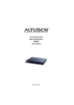
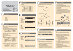
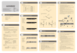
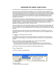
3
6
The KM0832 (Front View)
1
2
Single Stage Installation Diagram
1
3
KA9222 Console Module
4
6
3
5
Online Registration
International:
• http://support.aten.com
North America:
• http://www.aten-usa.com/product_registration
KM0832 Matrix KVM Switch Quick Start Guide
®
© Copyright 2010 ATEN International Co., Ltd. www.aten.com
Altusen and the Altusen logo are trademarks of ATEN International Co., Ltd.
All rights reserved. All other trademarks are the property of their respective owners.
This product is RoHS compliant
1
PAPE-1214-K00G Printing Date: 08/2010
Technical Phone Support
International:
• 886-2-8692-6959
China:
• 86-10-5255-0110
Japan:
• 81-3-5323-7178
Korea:
• 82-2-467-6789
North America:
• 1-888-999-ATEN Ext: 4988
United Kingdom:
• 44-8-4481-58923
Package Contents
4
5
1. Power LED
2. Port LEDs
3. User Port LEDs
4
• 1 KM0832 Matrix KVM Switch
• 1 Power Cord
• 1 Rack Mount Kit (Brackets and Philips hex head screws M3 x 8)
• 1 Foot Pad Set (4 pcs.)
• 1 User Manual
• 1 Quick Start Guide
6
4. Reset Button
5. User Port 1 Switch
6. User Port 1
2
5
3 4
6
1. Power Socket
2. Power Switch
3. Configuration Port
4. Firmware Upgrade Switch
7
KA9272 Console Module
7
The KM0832 (Rear View)
1
The complete KM0832 package consists of:
8
5. Grounding Terminal
6. Chain Out Port
7. User Port
8. KVM Ports
Cascaded Installation
Up to two additional levels of KM0832 Matrix KVM switches may be cascaded from the
KM0832's CPU ports.
1. Make sure that power to all the devices you will be connecting up has been turned off.
2. Use Cat 5 cable to connect any 8 CPU Ports on the First Stage KM0832 unit to the User
Ports on the Second Stage KM0832 unit.
Note: 1. The distance between the First and Third Stage KM0832 units must not exceed
300m (1000').
2. We strongly recommend that you use Cat 5 shielded twisted pair (STP) cable.
3. Use CPU Modules to connect any available CPU Port on the KM0832 to the keyboard, video
and mouse ports of the computers you are installing.
4. Plug the Second Stage unit's power cable into an AC source; plug the power adapter cable
into the unit's Power Socket.
5. Repeat steps 2 - 4 for any other Second Stage units you wish to install.
6. Repeat steps 2 - 5 for any Third Stage units you wish to install.
7. Turn on the power for the First Stage unit. Wait one minute.
8. Turn on the power for the Second Stage units. Wait one minute.
9. After all the Stations are on, power on the computers.
KA9222 Console Module
2
5
Single Stage Installation
Requirements
Console
• A VGA, SVGA, or Multisync monitor capable of the highest resolution that you will be using
on any computer in the installation.
• Either a PS/2 or a USB keyboard and mouse.
Computers
• An HDB-15 video port or, for legacy Sun systems, a Sun 13W3 video port.
• Either a PS/2 style (6 pin mini-DIN) mouse port and PS/2 style keyboard port; or USB ports
(for a USB keyboard and USB mouse); or, for legacy Sun systems, a Sun style keyboard port
(8 pin mini-DIN).
CPU Module
2
1. Connect the Console (keyboard, monitor and mouse) to the Console Module.
2. Connect the Console Module to a User Port on the KM0832.
3. Connect the CPU Module to the KM0832 using Cat 5 cable.
Note: 1. The distance between any Console Module and any CPU Module must not
exceed 300m (1000').
2. We strongly recommend that you use Cat 5 shielded twisted pair (STP) cable.
4. Connect the CPU Module to the computer. Repeat steps 1 - 4 for all consoles and
computers that you wish to connect.
5. After all the computers have been connected, plug the female end of the power cord into the
KM0832's Power Socket; plug the male end into an AC power source.
6. For each Console Module, plug its power adapter into an AC power source; plug the power
adapter cable into the unit's power jack.
7. Turn on the power to the KM0832.
8. Turn on the power to the computers.
8
Daisy Chained Installation
Note: If the daisy chain feature is not operative on your unit, you will need a newer version of the
firmware. Contact your dealer for details.
1. Make sure that power to all the devices you will be connecting up has been turned off.
2. Use a daisy chain cable set to connect the Chain Out port of the parent KM0832 unit to the
Chain In port of the child KM0432 unit.
3. If you wish to install any consoles on this switch, follow the procedure described for the Single
Stage Installation.
4. Use CPU Modules to connect any available CPU Port on the KM0432 to the keyboard,
video and mouse ports of the computers you are installing.
5. Repeat the above steps for any additional KM0432 units you wish to add to the chain.
6. Plug the power cord into an AC power source and into the KM0832's power socket.
7. Switch on the power for the KM0832. Wait one minute for the unit to
ascertain its position.
8. Switch on the power for each KM0432 Station on the installation in turn. In each case, wait for
the Station ID to be ascertained and displayed on the current station before powering on the
next one.
9. After all the Stations are up, power on the computers.
10
KM0832 Administrator Utility 2
The menu items at the top of the main screen are used to search for, and configure the KM0832
stations and ports, as well as manage user accounts.
The function of each menu item is described in the following table:
Menu Item
Description
VIEW
Click to open the View page and set screen viewing options.
SETTINGS
ADMINISTRATION
Account
User
Management Management
Group Management
Port Management
Station Management
Super Adm
Configuration
KM0832
Click to open the Settings page, which allows users to
change account passwords and set other OSD preferences.
Administrators can Add, Modify, or Delete user accounts;
or, select a user from the list to change the user's password,
group membership, and user type.
Administrators can Add, Modify, or Delete group accounts.
Click to open the Port Select page. Administrators can click
on a Port ID to configure the port.
Click to open the Station Management page, which allows
administrators to change the station name and set the
Webpage Session Timeout.
Set Network
Click to open the Network Settings page, which allows the
Super Administrator to change DHCP, SMTP server, and
network settings.
Date & Time
Click to open the Date & Time page, which allows the Super
Administrator to set the date and time of the KM0832.
System
Information
Click to open the System Information page, which displays
general system settings.
SEARCH
Click to open the Search page. Users can search the
KM0832 station and attached computer names by inputting
key strings.
The icons on the bar at the top of the screen are for use only by administrators (except for the
Logout icon). The function of each icon is described in the following table:
Icon
UPGRADE
KM0432
BACKUP
SESSION
LOG
LOGOUT
HELP
Description
Click to open the Firmware Upgrade page, which allows the Super Administrator to upgrade the firmware
version.
Click to open the Backup and Restore Settings page. It allows administrators to backup the system configuration to a
local computer, or to restore a system configuration to the station.
Administrators can click to view all active sessions. Select a session and click End Session to force a user logout.
Administrators can click to open the Event Log dialog box. To view log data, enter a date range in the From and
To fields, and click OK.
Click to logout from the KM0832 and close the session.
Click to open the KM0832 help file.
12
OSD Operation
Basics:
1. Tap the [Scroll Lock] key twice to bring up the OSD Main Screen.
2. When the login screen appears, key in a valid username and password, and then press [Enter].
Note: The first time that the OSD is run, or if the password function has not been set, simply
press [Enter].
3. The OSD always starts in List view, with the highlight bar at the same position it was in the last time it was closed.
The simplest way to access a port is to either double-click it, or move the highlight bar to it, and then press [Enter].
OSD Main Screen Headings:
Heading
Explanation
This column lists the Port ID numbers (Station Number – Port Number) for all the CPU ports on
the installation. The simplest method to access a particular computer is to move the
Highlight Bar to it, and then to press Enter
PN
TYPE
Lists the type of CPU Module used to attach the computer.
NOTE
If a port has been given a name, its name appears in this column.
OSD Navigation:
• To dismiss the Main Screen, and deactivate the OSD, Click the X at the upper right corner of the OSD Window; or
press [Esc].
• To Logout, press [F8] on the keyboard, or click F8 on the OSD menu bar.
• To move up or down through the list one line at a time, Click the Up and Down Triangle symbols or use the Up and
Down Arrow Keys.
• To move up or down through the list one screen at a time, click the Up and Down Arrow symbols or use the [Pg Up]
and [Pg Dn] keys.
• To activate a port, double-click on it, or move the Highlight Bar to it, and then press [Enter]. After performing any of
the above mentioned actions, you automatically return to the previous menu.
OSD Functions:
Description
Function Name
F1
HELP
F2
F7
VIEW VIEW allows you to broaden or narrow the scope of which ports the OSD displays (lists) on the main Screen.
SET allows the Administrator and Users to set up their own working environments.
SET A separate profile for each is stored by the OSD and is activated according to the Username that was provided
during Login.
ADM is an Administrator Only function that allows the Administrator to configure and control the overall
ADM
operation of the OSD.
SCH Please refer to the SEARCH function under
.
SCAN allows you to automatically switch among the available computers at regular intervals so that you can
SCAN monitor their activity without having to take the trouble of switching yourself.
F8
LOUT LOUT is used to log out of your current OSD session.
F3
F4
F5
Displays information about the user and briefly describes each OSD function.
KA9222 Console Module
Next
KM0432
11
Hotkey Operation
13
Specifications
Function
9
KM0832 Administrator Utility 1
The KM0832 Administrator
Utility is a browser-based
application that enables
administrators to manage users,
groups, stations, and ports;
configure network settings;
upgrade firmware; and backup
and restore configurations. Users
can change their account
passwords and configure personal
profile preferences. The default IP
Address to connect to the
KM0832 Administrator Utility is
192.162.0.10
Invoking Hotkey Mode (HKM)
1. Press and hold down the Num Lock key.
2. Press and release the Minus key.
3. Release the Num Lock key.
[Num Lock]+[-]
Computer Connections
[Port ID] [Enter]
[T] [n] [Enter]
[A]
[ ]
[ ]
[B]
The switch accesses the computer that corresponds to that Port ID.
Sets the Auto Scan interval to n seconds – where n is a number from 1-255
Invokes Auto Scan Mode. When Auto Scan Mode is in effect, [P] or left
clicking the mouse pauses Auto Scanning. When Auto Scanning is paused,
press any key or Left Click the mouse to resume Auto Scanning.
Skips from the current port to the first previous accessible port.
Skips from the current port to the next accessible port.
Toggles the Beeper On or Off.
Max.
8,000 (via Cascade)
8
Port Selection
Hotkey Summary
[Num Lock]
+ [-]
32
Console Connections
Connectors
Switches
LEDs
Emulation
KM0832
Direct
OSD, Hotkey
Console Ports
8 x RJ-45 Female (Black)
KVM Ports
32 x RJ-45 Female (Black)
Daisy Chain Out Ports
1 x HPDB-50 Female (Black)
Configuration
1 x RJ-45 Female (Black)
Maintenance
1 x RJ-45 Female (Black)
Power
1 x 3-prong AC Socket
Reset
1 x Semi-recessed Pushbutton
Power
1 x Rocker
F/W Upgrade
1 x Slide
User Port 1
1 x Slide
On Line (Console Port)
8 (Green)
On Line/Selected (KVM Port)
32 Dual Colored (Green/Red)
Power
1 (Blue)
Keyboard/ Mouse
PS/2; USB (PC, Mac, Sun); Serial
Video
1024x768@60Hz (300m)
Scan Interval
1–240 seconds
I/P Rating
100–240VAC, 50/60Hz; 1A
Power Consumption
Environment
Physical Properties
120V/19W; 230V/20W
Operating Temp.
0–50°C
Storage Temp.
-20–60°C
Humidity
0–80% RH, Non-condensing
Housing
Metal
Weight
4.90 kg
Dimensions (L x W x H)
43.36 x 38.00 x 4.40 cm (19”/1U)