1
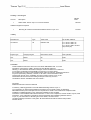
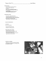
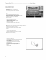
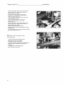
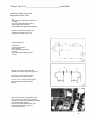
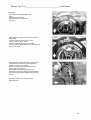
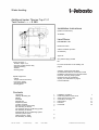
Water heating
Additional heater Thermo Top Z / C
Test Control ~ ~ ~ S 289
Installation Instructions
(Guide for instructions)
TT9903/04
Land Rover
DEFENDER Td5
Model Year 1999
Valid for all series (in terms
accessories)
Type: RF
Only valid for flying models
left
Legend of Figure 1
1Thermo Top Z / C-D
2Security system and fan relay
3Clock screening
4Muffler
5Dosing pump
For more information on the validity, see
page 2
Vehicles, engine types and series
accessories that are not mentioned in these
installation instructions have not been tested.
However, mounting obeying these
instructions may be considered.
Anyway, the instructions on page 2
must be followed!
Specific equipment
Collets
Torque wrench with a step
from 2.0 to 10 Nm
Seat E5 TORX 3/8 "
Riveting pliers
Contents
Land Rover
Heating / Mounting Kit
Validity
Preamble
General Tips
Preparatory tasks
Location of heater
Security system and fan relay
Fan mounting in vehicles
not equipped with air-conditioning system
Fan mounting in vehicles
equipped with an air conditioning system
Clock and preset option
setting summer / winter
Pre-assembly of heating
Ident.-Nr. 675 05D
Printed in Germany
04/03
Druck: Steffen
1
2
2
2
3
3
3
4
Installation of heating
Positioning relative to the circuit
water and non-return valve
Combustion air supply
Exhaust duct
Fuel inlet
Final tasks
4
5
6
7
© Webasto Thermo GmbH Germany
7
9
11
11
12
16
Thermo Top Z / C_________________________________Land Rover
Heating / mounting kit
Amount
1
Number
Order
Description
Water heater Thermo Top Z / C-D and accessories
892 44A
Additional equipment required:
1
Mounting Kit Land Rover Defender Model 99 Thermo Top Z / C-D
675 02A
Validity
Manufacturer
Type
Trade name
No. EG-BE / ABE No.
Land Rover
LD
Defender Td5
e11 * 96/79 * 0086 * 02
e11 * 96/79 * 0086 * 05
e11 * 96/79 * 0086 * 06 H571
(Car) K738 (car)
Engine Type
Category Engine
Performance in kW
Cm3 Cylinders
10P
Diesel
90
2,495
15P
Diesel
90
2,495
Preamble
These installation instructions refer to the Land Rover DEFENDER Td5 - For more
information concerning the validity, see the front page-Models 1999 and
following, to the extent that the technical changes of recent models have no influence
on mounting. We disclaim all responsibility for mounting on a newer vehicle
the models 1999. According to the standard vehicle and its accessories, additional instructions
may be required during assembly. However, in all cases, it will be essential to follow
requirements set forth in the "Installation and User's Guide" Thermo Top Z / C We
will therefore follow the instructions editing techniques when they are not in
contradiction with the "Installation and User's Guide."
CAUTION:
Additional instructions must be observed!
In Germany, obtaining permission to install additional heating Thermo Top Z / C
is not required if you follow these installation instructions since a specific section of descriptive
ABG addresses this point. Exemption from the requirement to obtain a new certificate of compliance after
installation of additional heating is only valid if the installation is fully compliant
instructions in the installation instructions below here. In case of non-compliance, however small it may be, these
instructions, a new certificate of compliance must be submitted (see installation guidelines Thermo
Top Z / C). The instructions in "Mounting and User's Guide," as well as those
complete assembly instructions in this guide. All these elements should be retained and provided
with the vehicle.
2
Thermo Top Z / C_________________________________Land Rover
General Tips
- Protect the bare parts of the body,
such as holes, with an anticorrosive
- Pipes, ducts and cables should be
covered by protective pipes where they
are vulnerable
- The acute angles must be covered
corner guards (supply pipe cut).
Preparatory tasks
- Report the number plate factory
original identification plate on the new
- Remove the incorrect year on the new plate
-Amenerlanouvelleplaque (plate
Identification) to the desired location.
Engine compartment
CAUTION:
Remove the battery!
- Remove the engine cover
- Disable the cooling system
Outer part of the vehicle
- Open the tank cap, air tank
- Remove the tank in accordance with
manufacturer's instructions
- Remove the insulation system sound on
right side of the chest wheel.
Location of heating
Heating (2/1) must be mounted horizontally
in the engine compartment, to the right from
the direction of travel.
3
Thermo Top Z / C_________________________________Land Rover
Security system and relay
fan
- Positioning the ends of the plate
Connection of the safety system (3/3) of
fan relay (3/1) and the ground terminal
on the mounting bracket as shown in Figure 3.
- Drill a bore of a diameter of 2.5 mm for the
security system, and a diameter of 4.0 mm
for the fan relay and backsplash.
- Fix the plate terminal system
security with metal screws 3,5 x13, and relay
fan and backsplash with metal screws
5.5 x9, 5
- Replace the security system on
connecting plate
- Connect the positive terminal of connector
the positive terminal of the starter
- Secure the wiring harness heating
the installation location of the
heating
- Secure the wiring harness from the clock
screening and flush with fan
cables available
- Set down the wiring harness from the pump
metering, along the cables located on the brake
headboard
TIP:
For all work on the cables, ensure
provide good protection against abrasion.
4
Thermo Top Z / C_________________________________Land Rover
Implementation of the fan
- Separate connector green / purple (4/2, 4/4)
theft security system (15A) near the
fan, as shown in Figure 4
- Fix circular connectorse
- Install connectors in accordance with the scheme
of Figure 5cffffffffffffffffffffffffffffffffffffffffffffff
- Connect the black connector (4/5) Fan K3/30
and connector Green / Purple (4/2) near the fan
- Connect the red connector (4/1) relay
K3/87a fan and connector green / purple (4/2)
the anti-theft security system (15A)
5
Thermo Top Z / C_________________________________Land Rover
Clock and preset option
setting summer / winter
CAUTION:
When mounting the clock preselection
not exert any pressure on the LCD screen.
TIP:
It is recommended to choose the location
presented to install the preset clock (6/2)
button and the summer / winter (6/1)! Please validate
installation location to your customers
before mounting.
- Place the template for the clock
Preset the desired location
- Operate two holes along the template
- Remove the template
- Fit the guide tube with sheet metal screws
TIP:
Pay attention to the direction of the ratchet teeth (see instructions
mounting)! When replacing the beam
electrical, pay attention to the protection against
friction!
- Run the wiring harness clock
screening through the aperture and securing the
lid
- Replace the clock screening
- Remove the baffle (6/3)
- Set the drilling of the summer / winter switch (6/1)
in the desired position and perform a bore
12 mm diameter
- Fix the summer / winter switch with washer
notched and a nut
- Connect the brown and purple connectors in
the switch as shown in Figure 7 (taken
bottom)
- Refit the baffle
6
Thermo Top Z / C_________________________________Land Rover
Pre-assembly of heating
- Shorten the exhaust piping
as shown in Figure 8
- Tighten the bolts (9/1, 2, 3) in the heating
(No 10 Nm) zzzzzzzzzzzzzzzzzzzzzzzzzzzzzz
- Replace the exhaust piping (9/6)
heating and secure it with a clamp
(9/5)
- Train the exhaust piping as
shown in Figure 9 eeeeeeeeeeeeeeeeeeeeeee
- Put two washers (9/4) on the
lower studs (9/3)
Installation of heating
- Move the template (10/1) on the trunk Wheel
as shown in Figure 10 and the position
bore (10/2, 3)
- Make a hole (10/2, 3) 8 mm diameter
in the trunk wheel
- Fold the ends drilled as indicated
Figure 11
7
Thermo Top Z / C_________________________________Land Rover
- Mount the bracket (12/5) on the wheel as safe
shown in Figure 12, using 2 M6x20 screws, 2
washers and 2 nuts collars
- Attach the strap (12/3) at the short ends
support with a screw M6x20 (12/4) and a nut
collar as shown in Figure 12
- Align the support and position the bore (12/2)
on the support rod (12/1)
- Remove again the support and the belt
- Make a hole diameter of 7 mm (12/2)
the support rod
- Mount the bracket (12/5) on the wheel as safe
shown in Figure 12, using 2 M6x20 screws, 2
washers and 2 nuts collars
- Mount the belt (12/3) ends the long
support rod (12/1) with a screw M6x16 (12/2) and
one flange nut
- Insert the heater (13/1) on the bracket and secure
with 3 nuts collars (13/2, 3, 4)
TIP:
Pay attention to the two washers on both
lower studs (13/2)
- Align the bracket with heating belt and
perform the set screw connections
- Replace the harness on heating
- Connect the power supply to the socket Mecanyl
heating through a flexible cable and clamps
clamping
- Leading power and beam Mecanyl
electric metering pump down
8
Thermo Top Z / C_________________________________Land Rover
Positioning relative to the circuit
water and non-return valve
TIP:
Secure all hose clamps with a pitch of 2.0
+ 0.5 Nm!
Recovering the liquid flowing cooling
with an appropriate container!
Install flexible water pipes without twisting!
Below you will find the representation
installing the heating circuit in line
Cooling of the vehicle (Figure 14)
Legend to Figure 14:
1 Expansion
2 Cooling Thermostat
Motor Vehicle 3
4 Circulation pump (heating)
5 Heating
6 Heat exchanger heating (vehicle)
7 Cooler
Cut
- Shorten the contour of the water pipe
flexible two sections as shown in Figure 15:
1 x 40 mm + 180 ° bend (15/1) (input
water heating to the engine output)
1 x 40 mm + 90 ° bend (15/2) (the output
water heating of the heat exchanger
vehicle)
Cut
- Disconnect the water hose flexible vehicle
(16/1) of the engine of the heat exchanger
vehicle with forceps and discarding the support
pipe (keep the pipe support)
- Cut the water pipe flexible vehicle (16/1)
level marks indicated on Figure 16
- Clean the hose (16/1)
9
Thermo Top Z / C_________________________________Land Rover
- Replace the hose water hose curvature
180 ° (17/1) on the water inlet of the heating, tilt
down and secure it with a clamp
- Connecting the flexible water pipe (17/1) in water pipe
flexible vehicle (17/2) at the output
motor using a connection pipe 20x15
and 2 clamps
- Connecting the flexible water hose of a curvature of 90 °
(18/3) of flexible water pipe of the vehicle (18/1),
level of the heat exchanger, using a
connecting tube 20x15 and 2 clamps
- Put the flexible water pipe (18/3) on the output
water heating and connect with a hose
Tightening
- Replace the plastic support (18/2) of the vehicle
CAUTION:
During assembly of the non-return valve, to
Note the direction of conduction!
- Disconnect the connector (19/1) from the end of
pipe (19/4) of the expansion vessel
- Insert the check valve (19/3) at the end
the pipe (19/4) (direction of conduction from the engine to
the expansion) and secure with a hose
Tightening
- Secure the vehicle connector (19/1) using
a hose (19/2) and two clamps
10
Thermo Top Z / C_________________________________Land Rover
Exhaust duct
- Place the cover (20/1) of the conduit
exhaust ports (20/2)
- Put the exhaust conduit (20/2) on the
heating, and secure it with a clamp,
as shown in Figure 20
- Attach the exhaust duct (20/2) with a cord
cable
Flue
CAUTION:
When assembling the flue, ensure that there
has a sufficient distance between the pipes and
cables! especially careful to maintain this
sufficient distance cables for vehicles
provided with an air conditioning system!
- Remove the securing bolt of the fairing wheel
- In space, attach the elbow (21/4)
the fairing wheel using the center hole,
as shown in Figure 21, using a screw
M6x20, a nut body and a collar nut
- Fasten the exhaust silencer (21/2) at room
angled (21/4) as shown in Figure 21, with
M6x20 screw and flange nut
- Put the exhaust conduit (21/1)
Heating of the muffler, and set
with a clamp
- Place the end of the exhaust duct (21/3)
exhaust silencer, attach a collar
tightening and towards the bottom, as shown in
Figures 21 and 22
- Make a hole diameter of 9 mm (22/1) in the
chassis as shown in Figure 22, and insert a
nut M6
- Attach the end of the exhaust duct (22/3) with
a clamp (22/2), a screw and a M6x20
spring washer for the nut (22/1)
- Align the end of the exhaust pipe as
shown in Figure 22
11
Thermo Top Z / C_________________________________Land Rover
Fuel inlet
CAUTION:
Install the fuel conduit so that it
can be protected in case of falling rocks! In
sharp edges, protect against friction
the fuel conduit and the harness!
TIP:
Be sure to install the metering pump in the correct location,
To do this, refer to the "Installation Guide".
Dosing pump
- Make a hole diameter of 9 mm fixing
the metering pump (23/4) and insert a M6 nut.
- Attach the metering pump (23/4) metal stamp
with a flexible clamp (23/6) and a nut
collar, as shown in Figure 23
- Lead the electrical harness (23/2) of the dosing pump
and the fuel conduit Mecanyl (23/1) along the
fuel lines of the vehicle, of the spar
frame right to the dosing pump
- Shorten the harness (23/2) at
the dosing pump, the duct away
rubber, position the lid, close and secure the
harness to the dosing pump.
- Shorten the fuel line (23/1)
Mecanyl, and connect it to the upper face of the
metering pump (side of the cover), with a cable
hose (23/3) and a clamp
12
Thermo Top Z / C_________________________________Land Rover
Fuel levy
- Cut the end of the sampling line fuel
(24/1)
- Shorten the riser 300 mm
- Insert the riser in the removal of
fuel (24/1)
- Replace the hose (25/2) on the riser and secure
with a clamp
- Insert the fuel line Mecanyl (25/1) in the
hose and secure with a clamp
- Attach fuel line Mecanyl (25/1) on the tank
of the vehicle along the vehicle's connectors and fix
with a power cable
- Reassemble the vehicle tank in accordance with
manufacturer's instructions and the lead pipe
Mecanyl fuel along the fuel lines
vehicle, to the right side member and moving
to the metering pump (26/1)
- Cut the fuel conduit Mecanyl (26/3) at the
low pressure plug of the dosing pump and attach
the metering pump with a flexible hose (26/2) and
clamp
- Attach the fuel lines and wiring harness
with bead wires
13
Thermo Top Z / C_________________________________Land Rover
14
Thermo Top Z / C_________________________________Land Rover
15
Thermo Top Z / C_________________________________Land Rover
Final tasks
- Reinstall the vehicle battery
- Reinstall the removed parts in the reverse order of disassembly
- Check that all cables, hoses, connectors and clamps, as well as all connections
power are secured
- Cover all connectors with a loose cable cord
- Protect the components of heating with anti-corrosive wax (Tectyl ML, No.
Command: 111329)
- Start the engine and bleed the water according to the instructions of the vehicle manufacturer,
refilling the liquid cooling
- Set the vehicle heater to "warm" and adjust the fan level 2
- Switch on the Webasto heater, see the "installation instructions / manual"
16
No.
order
Description
67366A
RISER FOR ROVER DISCOVERY TD5
1
67503A
BAG SMALL PARTS LAND ROVER DEFENDER TD5
1
Amount
152560
SPRING WASHER DIN128-A6-PHRF
1
19445A
COLLET NUT M6
3
242780
ELBOW ROOM
1
24304A
WASHER DIN9021-A7 0.4 ST-A3G
1
337749
NUT M6 x15.5
2,
36189A
6kt-SCHR.DIN933-M6X16-8.8-A3G
1
67365A
SUPPLY PIPE 4.5 bis 7.5 x3
1
88837A
WAY VALVE 2X8 K-PROT ENVELOPE.
1
90290B
CONNECTING TUBE 20 X 15
2
91885A
FIX. EJOT DG60X14, 5/M6X15, 5 / E5DACRO500
3
67504A
SUPPORT LAND ROVER DEFENDER TD5
1
67505A
ABB LAND ROVER DEFENDER TD5 TT-C
1
67506A
ABG LAND ROVER DEFENDER TD5 TT-C
1