1
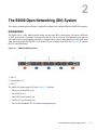
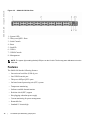
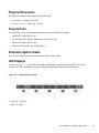
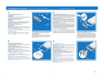
Dell Networking S6000-Open
Networking (ON) Installation
Guide
Publication Date: April 2014
Notes, Cautions, and Warnings
NOTE: A NOTE indicates important information that helps you make better use of your computer.
CAUTION: A CAUTION indicates either potential damage to hardware or loss of data and tells you how to
avoid the problem.
WARNING: A WARNING indicates a potential for property damage, personal injury, or death.
Information in this publication is subject to change without notice.
Copyright © 2014 Dell Inc. All rights reserved. This product is protected by U.S. and international copyright and intellectOctober
2014ual property laws. Dell and the Dell logo are trademarks of Dell Inc. in the United States and/or other jurisdictions. All other
marks and names mentioned herein may be trademarks of their respective companies.
April 2014
Contents
1 About this Guide
Related Publications . . . . . . . . . . . . . . . . . . . . . . . . . . . . . . . . . . . . . . . . . . . . . . . . . . 7
2 The S6000-Open Networking (ON) System
Introduction . . . . . . . . . . . . . . . . . . . . . . . . . . . . . . . . . . . . . . . . . . . . . . . . . . . . . . . . . 9
Features . . . . . . . . . . . . . . . . . . . . . . . . . . . . . . . . . . . . . . . . . . . . . . . . . . . . . . . . . . 10
Physical Dimensions . . . . . . . . . . . . . . . . . . . . . . . . . . . . . . . . . . . . . . . . . . . . . . . . . 11
Chassis Ports . . . . . . . . . . . . . . . . . . . . . . . . . . . . . . . . . . . . . . . . . . . . . . . . . . . . . . 11
Determine System Status . . . . . . . . . . . . . . . . . . . . . . . . . . . . . . . . . . . . . . . . . . . . . 11
LED Displays. . . . . . . . . . . . . . . . . . . . . . . . . . . . . . . . . . . . . . . . . . . . . . . . . . . . . . . 11
Basic Installation Requirements . . . . . . . . . . . . . . . . . . . . . . . . . . . . . . . . . . . . . . . . 12
Orderable S6000-ON Components. . . . . . . . . . . . . . . . . . . . . . . . . . . . . . . . . . . . . . 13
3 Site Location and Preparation
Site Selection . . . . . . . . . . . . . . . . . . . . . . . . . . . . . . . . . . . . . . . . . . . . . . . . . . . . . . 15
Cabinet Placement . . . . . . . . . . . . . . . . . . . . . . . . . . . . . . . . . . . . . . . . . . . . . . . . . . 16
Rack Mount . . . . . . . . . . . . . . . . . . . . . . . . . . . . . . . . . . . . . . . . . . . . . . . . . . . . . . . . 16
Ground . . . . . . . . . . . . . . . . . . . . . . . . . . . . . . . . . . . . . . . . . . . . . . . . . . . . . . . . . . . 16
Fans and Airflow . . . . . . . . . . . . . . . . . . . . . . . . . . . . . . . . . . . . . . . . . . . . . . . . . . . . 16
Fan Combinations . . . . . . . . . . . . . . . . . . . . . . . . . . . . . . . . . . . . . . . . . . . . . . . 16
Power . . . . . . . . . . . . . . . . . . . . . . . . . . . . . . . . . . . . . . . . . . . . . . . . . . . . . . . . . . . . 17
Storing Components . . . . . . . . . . . . . . . . . . . . . . . . . . . . . . . . . . . . . . . . . . . . . . . . . 17
4 Install the S6000-ON
Unpack the S6000-ON System . . . . . . . . . . . . . . . . . . . . . . . . . . . . . . . . . . . . . . . . . 19
Package Contents . . . . . . . . . . . . . . . . . . . . . . . . . . . . . . . . . . . . . . . . . . . . . . . 19
Unpacking Steps . . . . . . . . . . . . . . . . . . . . . . . . . . . . . . . . . . . . . . . . . . . . . . . . 20
Install Rack or Cabinet Hardware . . . . . . . . . . . . . . . . . . . . . . . . . . . . . . . . . . . . . . . 20
Rack Mount Safety Considerations . . . . . . . . . . . . . . . . . . . . . . . . . . . . . . . . . . 20
Installing the Dell ReadyRails System . . . . . . . . . . . . . . . . . . . . . . . . . . . . . . . . 21
Configuring a Two-Post Flush-Mount . . . . . . . . . . . . . . . . . . . . . . . . . . . . . . . . 22
Configuring a Two-Post Center-Mount . . . . . . . . . . . . . . . . . . . . . . . . . . . . . . . 23
Configure a Four-Post Thread . . . . . . . . . . . . . . . . . . . . . . . . . . . . . . . . . . . . . . 24
Installing the S6000-ON System . . . . . . . . . . . . . . . . . . . . . . . . . . . . . . . . . . . . . . . . 25
Installing a 1U Front-Rack . . . . . . . . . . . . . . . . . . . . . . . . . . . . . . . . . . . . . . . . . 25
Attaching the Ground Cable . . . . . . . . . . . . . . . . . . . . . . . . . . . . . . . . . . . . . . . . . . . 26
Installing an AC Power Supply. . . . . . . . . . . . . . . . . . . . . . . . . . . . . . . . . . . . . . 27
Installing QSFP+ Optics . . . . . . . . . . . . . . . . . . . . . . . . . . . . . . . . . . . . . . . . . . . . . . 29
Removing QSFP+ Optics. . . . . . . . . . . . . . . . . . . . . . . . . . . . . . . . . . . . . . . . . . 29
|
3
www.dell.com | support.dell.com
Power Up the S6000-ON System . . . . . . . . . . . . . . . . . . . . . . . . . . . . . . . . . . . . . . . 29
Power Up Sequence . . . . . . . . . . . . . . . . . . . . . . . . . . . . . . . . . . . . . . . . . . . . . 30
5 Power Supplies
Components . . . . . . . . . . . . . . . . . . . . . . . . . . . . . . . . . . . . . . . . . . . . . . . . . . . . . . . 31
Installing an AC Power Supply . . . . . . . . . . . . . . . . . . . . . . . . . . . . . . . . . . . . . . . . . 32
Replacing an AC Power Supply . . . . . . . . . . . . . . . . . . . . . . . . . . . . . . . . . . . . . . . . 33
After Installing the S6000-ON . . . . . . . . . . . . . . . . . . . . . . . . . . . . . . . . . . . . . . . . . . 33
6 Fans
Components . . . . . . . . . . . . . . . . . . . . . . . . . . . . . . . . . . . . . . . . . . . . . . . . . . . . . . . 35
Installing a Fan Module . . . . . . . . . . . . . . . . . . . . . . . . . . . . . . . . . . . . . . . . . . . . . . . 36
Replacing a Fan Module . . . . . . . . . . . . . . . . . . . . . . . . . . . . . . . . . . . . . . . . . . . . . . 36
7 Management Ports
Accessing the RS-232 Console Port. . . . . . . . . . . . . . . . . . . . . . . . . . . . . . . . . . . . . 37
Accessing the Console Port. . . . . . . . . . . . . . . . . . . . . . . . . . . . . . . . . . . . . . . . 38
Accessing the USB-B Console Port . . . . . . . . . . . . . . . . . . . . . . . . . . . . . . . . . . . . . 38
8 Specifications
Chassis Physical Design. . . . . . . . . . . . . . . . . . . . . . . . . . . . . . . . . . . . . . . . . . . . . . 41
Environmental Parameters . . . . . . . . . . . . . . . . . . . . . . . . . . . . . . . . . . . . . . . . . . . . 41
Power Requirements. . . . . . . . . . . . . . . . . . . . . . . . . . . . . . . . . . . . . . . . . . . . . . . . . 42
AC Input Specification . . . . . . . . . . . . . . . . . . . . . . . . . . . . . . . . . . . . . . . . . . . . 42
IEEE Standards. . . . . . . . . . . . . . . . . . . . . . . . . . . . . . . . . . . . . . . . . . . . . . . . . . . . . 42
Agency Compliance . . . . . . . . . . . . . . . . . . . . . . . . . . . . . . . . . . . . . . . . . . . . . . . . . 42
Network Equipment Building Systems (NEBS) Compliance . . . . . . . . . . . . . . . 42
USA Federal Communications Commission (FCC) Statement . . . . . . . . . . . . . 43
Canadian Department of Communication Statement . . . . . . . . . . . . . . . . . . . . 43
European Union EMC Directive Conformance Statement . . . . . . . . . . . . . . . . . 43
Japan: VCCI Compliance for Class A Equipment . . . . . . . . . . . . . . . . . . . . . . . 44
Korean Certification of Compliance . . . . . . . . . . . . . . . . . . . . . . . . . . . . . . . . . . 44
Safety Standards and Compliance Agency Certifications . . . . . . . . . . . . . . . . . 45
Electromagnetic Compatibility (EMC) . . . . . . . . . . . . . . . . . . . . . . . . . . . . . . . . 45
Product Recycling and Disposal . . . . . . . . . . . . . . . . . . . . . . . . . . . . . . . . . . . . 46
9 Technical Support
The iSupport Website . . . . . . . . . . . . . . . . . . . . . . . . . . . . . . . . . . . . . . . . . . . . . . . . 47
Accessing iSupport Services . . . . . . . . . . . . . . . . . . . . . . . . . . . . . . . . . . . . . . . 47
Contacting the Technical Assistance Center . . . . . . . . . . . . . . . . . . . . . . . . . . . . . . 48
4
|
Requesting a Hardware Replacement . . . . . . . . . . . . . . . . . . . . . . . . . . . . . . . . . . . 48
|
5
6
|
www.dell.com | support.dell.com
1
About this Guide
This guide provides site preparation recommendations, step-by-step procedures for rack mounting and
desk mounting, and connecting to a power source.
CAUTION: To avoid electrostatic discharge (ESD) damage, wear grounding wrist straps when handling this
equipment.
WARNING: Only trained and qualified personnel can install this equipment. Read this guide before you install
and power up this equipment. This equipment contains two power cords. Disconnect both power cords before
servicing.
WARNING: This equipment contains optical transceivers, which comply with the limits of Class 1 laser
radiation.
WARNING: When no cable is connected, visible and invisible laser radiation may be emitted from the
aperture of the optical transceiver ports. Avoid exposure to laser radiation and do not stare into open
apertures.
Related Publications
For more information about the S6000-ON system, refer to the S6000-Open Networking (ON) Getting
Started Guide.
NOTE: For the most recent documentation and software, visit iSupport at http://www.dell.com/support.
About this Guide
|
7
8
|
About this Guide
www.dell.com | support.dell.com
2
The S6000-Open Networking (ON) System
This chapter contains general features, capabilities, and physical configurations the S6000-ON supports.
Introduction
The S6000-ON is a fully featured switch/router one rack unit (RU) system where you require 10Gb and/
or 40Gb connections. It contains 32 ports of 40G that you can use to create a configuration of 96 ports of
10G small form-factor pluggable plus (SFP+) (using breakout cables) and eight ports of 40G quad small
form-factor pluggable plus (QSFP+). The S6000-ON power supply unit (PSU) side (Figure 2-1) contains
the PSU and fan modules.
Figure 2-1.
S6000-ON PSU-Side View
1 - PSU 1
2 - Fan Modules 1-3
3 - PSU 2
The S6000-ON input/output (I/O) side (Figure 2-2) includes:
• Thirty-two fixed QSFP+ ports
• One USB 2.0 port
• One USB-B serial console port
• One RS-232 serial console port
• One 10/100/1000BaseT (RJ-45) Ethernet management port
The S6000-Open Networking (ON) System
|
9
www.dell.com | support.dell.com
Figure 2-2.
S6000-ON I/O-Side View
1 - System LED
2 - Thirty-two QSFP+ Ports
3 - Serial Console
4 - Reset
5 - Stack ID
6 - USB-A
7 - USB-B Console
8 - Management
NOTE: The system light emitting diodes (LEDs) are on the I/O side. The fan tray power indicators are on the
PSU side.
Features
The S6000-ON has the following features:
• One universal serial bus (USB-A) port
• One USB-B console port
• Thirty-two 40Gbps QSFP+ ports
• On-board central processing unit (CPU) system
• Temperature monitoring
• Software-readable thermal monitor
• Real time clock (RTC) support
• Hot-plugging redundant power supply
• Current monitoring for power management
• Removable fan
• Standard 1U chassis high
10
|
The S6000-Open Networking (ON) System
Physical Dimensions
The S6000-ON has the following physical dimensions:
• 434 x 460 x 43.5 mm (W x D x H)
• 17.09 x 18.11 x 1.71 inches (W x D x H)
Chassis Ports
The following is a list of the standard ports located on each S6000-ON chassis:
• Serial RS-232 port (RJ-45 type)
• Out of band (OOB) Ethernet management port (RJ-45 type)
• Thirty-two 40Gbps QSFP+ ports
• One universal serial bus port (USB Type-A)
Determine System Status
You can view S6000-ON status information with the system LEDs.
LED Displays
As shown in Figure 2-3, the S6000-ON includes LED displays on both the I/O and PSU side of the
chassis. For LED information, refer to your third-party operating software documentation.
Figure 2-3.
PSU and Fan Tray LEDs
1- Fan Tray 1-3 LEDs
2 - PSU 1-2 LEDs
The S6000-Open Networking (ON) System
|
11
www.dell.com | support.dell.com
1 - Serial Console
2 - Master LED
3 - Power LED
4 - Fan Status LED
5 - Locator LED
6 - Stack ID
7 - USB-A
8 - USB-B Console
9 - Management
Basic Installation Requirements
Detailed installation instructions for the S6000-ON are provided in Site Location and Preparation and
Install the S6000-ON. However, here is an initial list of components required for a successful installation
of the S6000-ON:
• S6000-ON chassis
• AC cables to connect the AC power source to each of the chassis’ AC power supplies (country/regional
configured)
• Mounting brackets for rack installation (included)
• Screws for rack installation and #1 and #2 Phillips screwdrivers (not included)
• Ground cable (not included, optional)
• Ground cable screws (included)
• Copper/fiber cables
12
|
The S6000-Open Networking (ON) System
Optional components for installation:
• Additional power supply units
• Additional fan modules
• Additional mounting brackets (if installing in a 4-post rack or cabinet)
Orderable S6000-ON Components
You can order the S6000-ON system in several different configurations. Also, you can order optional
modules and optics separately.
The following is a list of different configurations and modules:
• S6000-ON AC Normal Airflow: thirty-two 40Gbps QSFP+ ports, two AC power supplies, and three fan
subsystems (airflow from the I/O side to the PSU side)
• S6000-ON AC Reverse Airflow: thirty-two 40Gbps QSFP+ ports, two AC power supplies, and three fan
subsystems Fan with airflow from the I/O side to the PSU side
• Fan with airflow from the PSU side to the I/O side
• AC Power supply with airflow from the I/O side to the PSU side
• AC Power supply with airflow from the PSU side to the I/O side
The S6000-Open Networking (ON) System
|
13
www.dell.com | support.dell.com
14
|
The S6000-Open Networking (ON) System
3
Site Location and Preparation
The S6000-ON is suitable for installation as part of a common bond network (CBN). It can be installed
in:
• Network telecommunication facilities
• Data centers
• Other locations where the national electric code (NEC) applies
This chapter contains the following sections:
• Site Selection
• Cabinet Placement
• Rack Mount (Optional)
• Ground (Optional)
• Fans and Airflow
• Power
• Storing Components
NOTE: Install the S6000-ON system into a rack or cabinet before installing any optional components.
Site Selection
Install the S6000-ON in an restricted access area. A restricted access area is one in which service
personnel can only gain access using a special tool, lock, key, or other means of security and access is
controlled by the authority responsible for the location.
Ensure that the area where the S6000-ON system is installed meets the following safety requirements:
• Near an adequate power source. Connect the system to the appropriate branch circuit protection as
defined by your local electrical codes.
• Environmental temperature between 32° to 113°F (0° to 45°C).
• Relative humidity that does not exceed 90 percent non-condensing.
• In a dry, clean, well-ventilated and temperature-controlled room, away from heat sources such as hot air
vents or direct sunlight.
• Away from sources of severe electromagnetic noise.
• Positioned in a rack or cabinet, or on a desktop with adequate space in the front, rear, and sides of the
S6000-ON for proper ventilation and access.
Site Location and Preparation
|
15
www.dell.com | support.dell.com
Cabinet Placement
Install the S6000-ON only in indoor cabinets designed for use in a controlled environment as described in
Site Selection. Do not install the S6000-ON in outside plant cabinets.
The cabinet must meet the following:
• Minimum cabinet size and airflow are according to the Electronic Industries Alliance (EIA) standard.
Rack Mount (Optional)
When you prepare your equipment rack, ensure that the rack is earth ground. Ground the equipment rack
to the same ground point used by the power service in your area. The ground path must be permanent.
Ground (Optional)
Use the S6000-ON in a CBN. Connect the grounding cables as described in Install the S6000-ON.
Fans and Airflow
The S6000-ON fans support two airflow options. Be sure to order the fans suitable to support your site’s
ventilation. Use a single type of airflow fan in your system. Do not mix reverse and normal airflows in a
single S6000-ON chassis.
Fan Combinations
The S6000-ON has stock keeping units (SKUs) that support the following configurations. Installation of
the fans is done as part of the factory install based on SKU type.
• AC PSU with fan airflow from I/O to PSU
• AC PSU with fan airflow from PSU to I/O
All fans and PSUs in a configuration must be in the same airflow direction.
The S6000-ON supports three fan trays with airflow directions from the I/O to the utility or the utility to
the I/O.
For proper ventilation, position the S6000-ON in an equipment rack (or cabinet) with a minimum of
5 inches (12.7cm) of clearance around the exhaust vents. When you install two S6000-ON systems near
each other, position the two chassis at least 5 inches (12.7cm) apart to permit proper airflow. The fan
speed increases when the internal temperature reaches 72°C and decreases to normal speed when the
temperature falls to 58°C. The S6000-ON never intentionally turns off the fans.
16
|
Site Location and Preparation
Power
To connect the chassis to the applicable power source, use the appropriate power cord with the
S6000-ON system. An AC power cord (country/region specific) is included with the system.
When installing AC systems, follow the requirements of the National Electrical Code, ANSI/NFPA 70
where applicable.
The system is powered-up as soon as the power cord is connected between the system and the power
source.
CAUTION: Always disconnect the power cable before you service the power supply slots.
CAUTION: Use the power supply cord as the main disconnect device on the AC system. Make sure that the
socket-outlet is located/installed near the equipment and is easily accessible.
Storing Components
If you do not install your S6000-ON and components immediately, Dell Networking recommends
properly storing the system and all optional components until you are ready to install them.
Follow these storage guidelines:
• Storage temperature must remain constant ranging from -4° to 158° F (from -20°C to 70° C).
• Store on a dry surface or floor, away from direct sunlight, heat, and air conditioning ducts.
• Store in a dust-free environment.
WARNING: ESD damage can occur when components are mishandled. Always wear an ESD-preventive
wrist or heel ground strap when handling the S6000-ON and its accessories. After you remove the original
packaging, place the S6000-ON and its components on an anti-static surface.
Site Location and Preparation
|
17
www.dell.com | support.dell.com
18
|
Site Location and Preparation
4
Install the S6000-ON
To install the S6000-ON system, Dell Networking recommends completing the installation procedures in
the order presented in this chapter.
Always handle the S6000-ON and its components with care. Avoid dropping the system or its field
replaceable units (FRUs).
This chapter describes the installation procedures as follows:
• Unpack the S6000-ON System
• Install Rack or Cabinet Hardware
• Installing the Dell ReadyRails System
• Configuring a Two-Post Flush-Mount
• Configuring a Two-Post Center-Mount
• Configure a Four-Post Thread
• Installing the S6000-ON System
• Installing a 1U Front-Rack
• Attaching the Ground Cable (Optional)
• Installing an AC Power Supply
• Installing QSFP+ Optics
• Power Up the S6000-ON System
WARNING: ESD damage can occur if components are mishandled. Always wear an ESD-preventive wrist or
heel ground strap when handling the S6000-ON and its components. As with all electrical devices of this type,
take all the necessary safety precautions to prevent injury when installing this system.
Unpack the S6000-ON System
NOTE: Before unpacking the system, inspect the container and immediately report any evidence of damage.
Package Contents
When unpacking the S6000-ON switch, make sure that the following items are included:
• One S6000-ON switch
• One RJ-45 to DB-9 female cable
• Two sets of rail kits (no tools required)
• Two PSUs
Install the S6000-ON
|
19
www.dell.com | support.dell.com
• At least one AC power cord (country/region specific)
• Getting Started Guide
• Safety and Regulatory Information
• Warranty and Support Information
Unpacking Steps
1
2
3
4
5
Place the container on a clean, flat surface and cut all straps securing the container.
Open the container or remove the container top.
Carefully remove the switch from the container and place it on a secure and clean surface.
Remove all packing material.
Inspect the product and accessories for damage.
Install Rack or Cabinet Hardware
You may either place the switch on the rack shelf or mount the switch directly into a 19" wide, EIA-310E- compliant rack (four-post, two-post, or threaded methods). The Dell ReadyRails™ system is provided
for one 1U front-rack and two-post installations. The ReadyRails system includes two separately
packaged rail assemblies and two rails that are shipped attached to the sides of the switch.
WARNING: This is a condensed reference. Read the safety instructions in your Safety, Environmental, and
Regulatory information booklet before you begin.
NOTE: The illustrations in this document are not intended to represent a specific switch.
NOTE: Do not the use the mounted Ready-Rails as a shelf or a workplace.
Rack Mount Safety Considerations
• Rack loading — Overloading or uneven loading of racks may result in shelf or rack failure, causing
damage to the equipment and possible personal injury. Stabilize racks in a permanent location before
loading begins. Mount the components beginning at the bottom of the rack, then work to the top. Do not
exceed your rack load rating.
• Power considerations — Connect only to the power source specified on the unit. When multiple
electrical components are installed in a rack, ensure that the total component power ratings do not
exceed the circuit capabilities. Overloaded power sources and extension cords present fire and shock
hazards.
• Elevated ambient temperature — If installed in a closed rack assembly, the operating temperature of the
rack environment may be greater than the room ambient temperature. Use care not to exceed the 40°C
maximum ambient temperature of the switch.
• Reduced air flow — Install the equipment in the rack so that the amount of airflow required for safe
operation of the equipment is not compromised.
20
|
Install the S6000-ON
• Reliable earthing — Maintain reliable earthing of rack-mounted equipment. Pay particular attention to
the supply connections other than the direct connections to the branch circuit, for example: use of power
strips.
• Do not mount the equipment with the rear panel facing in the downward position.
Installing the Dell ReadyRails System
The ReadyRails rack mounting system is provided to easily configure your rack for installation of your
S6000-ON system. You can install the ReadyRails system using the 1U tool-less method or one of three
possible 1U tooled methods (two-post flush mount, two-post center mount, or four-post threaded).
Step
1
Task
With the ReadyRails flange ears facing outward, place one rail between the left and right vertical posts. Align and
seat the rear flange rail pegs in the rear vertical post flange. In Figure 4-1, item 1 and its extractions show how the
pegs appear in both the square and non-threaded round holes.
Figure 4-1.
1U Tool-less Configuration
2
Align and seat the front flange pegs in the holes on the front side of the vertical post. Refer to Figure 4-1, item 2.
3
Repeat this procedure for the second rail.
4
To remove each rail, pull on the latch release button on each flange ear and unseat each rail. Refer to Figure 4-1,
item 3.
Install the S6000-ON
|
21
www.dell.com | support.dell.com
22
Configuring a Two-Post Flush-Mount
Step
1
Task
For this configuration, remove the castings from the front side of each ReadyRails assembly. Refer to Figure 4-2,
item 1. To remove the two screws from each front flange ear (on the switch side of the rail) and remove each
casting, use a Torx driver. Retain the castings for future rack requirements. It is not necessary to remove the rear
flange castings.
Figure 4-2.
|
Two-Post Flush-Mount Configuration
2
Attach one rail to the front post flange with two user-supplied screws. Refer to Figure 4-2, item 2.
3
Slide the plunger bracket forward against the vertical post and secure the plunger bracket to the post flange with
two user-supplied screws. Refer to Figure 4-2, item 3.
4
Repeat this procedure for the second rail.
Install the S6000-ON
Configuring a Two-Post Center-Mount
Step
1
Task
Slide the plunger bracket rearward until it clicks into place and secure the bracket to the front post flange with two
user-supplied screws. Refer to Figure 4-3, item 1.
Figure 4-3.
Two-Post Center-Mount Configuration
2
Slide the back bracket towards the post and secure it to the post flange with two user-supplied screws. Refer to
Figure 4-3, item 2.
3
Repeat this procedure for the second rail.
Install the S6000-ON
|
23
www.dell.com | support.dell.com
24
Configure a Four-Post Thread
Step
Task
1
For this configuration, remove the flange ear castings from each end of the ReadyRails assemblies. To remove the
two screws from each flange ear and remove each casting, use a Torx driver. Refer to Figure , item 1. Retain the
castings for future rack requirements.
2
For each rail, attach the front and rear flanges to the post flanges with two user-supplied screws at each end. Refer
to Figure , item 2.
Figure 4-4.
|
Install the S6000-ON
Four-Post Threaded Configuration
Installing the S6000-ON System
You can mount the system in the 1U front-rack or 1U two-post (flush and center) configurations. The
following is an example of a front-rack configuration. For the 1U two-post (flush and center)
configurations, slide the system into the rails in the same manner as the four-post configurations.
Installing a 1U Front-Rack
You must configure the rails that are attached to the system.
Step
1
Task
Attach the switch rails (inner chassis members) to the S6000-ON system. Figure 4-5, item 3 shows the detail for
the front standoff with the locking tab.
Figure 4-5.
Attaching the Switch Rails
Install the S6000-ON
|
25
www.dell.com | support.dell.com
Step
2
Task
After you have installed both switch rails, line them up on the previously mounted Ready-Rails and slide the
switch in until it is flush with front of rack. About three inches prior to full insertion, the rail locking feature
engages to keep the switch from inadvertently sliding out of the rack and falling.
NOTE: Do not the use the mounted Ready-Rails as a shelf or a workplace.
Figure 4-6.
Front Rack Installation
Attaching the Ground Cable (Optional)
To attach the ground cable to the chassis, use a single M4x0.7 screw. The cable itself is not included with
the S6000-ON. To properly ground the chassis, Dell Networking recommends using a 6AWG one-hole
lug, #10 hole size, 63" spacing (not included in shipping). The one-hole lug must be a UL recognized,
crimp-type lug.
To connect the ground cable to the system, follow these steps:
CAUTION: Grounding conductors must be made of copper. Do not use aluminum conductors.
NOTE: The rack installation “ears” are not suitable for grounding.
NOTE: Coat the one-hole lug with an anti-oxidant compound prior to crimping. Also, bring any un-plated
mating surfaces to a shiny finish and coat with an anti-oxidant prior to mating. Plated mating surfaces must be
clean and free from contamination.
26
|
Install the S6000-ON
Step
Task
1
Take the one M4x0.7 screw from the package.
2
Cut the cable to the desired length. The cable length must facilitate proper operation of the fault interrupt circuits.
Dell Networking recommends using of the shortest cable route allowable.
3
Attach the one-hole lug to the chassis using the supplied 10-32 screw with the captive internal tooth lock washer.
Torque the screw to 20 in-lbs.
4
Attach the other end of the ground cable to a suitable ground point. The rack installation ears are not a suitable
grounding point.
Installing an AC Power Supply
The S6000-ON supports two hot-swappable PSUs with integrated fans that provide cooling for the
system. The S6000-ON supports AC power supplies with two air-flow directions (I/O to PSU or PSU to
I/O). Two PSUs are required for full redundancy, but the system will operate with a single PSU.
NOTE: S6000-ON ships with two PSUs. However, it is possible to run the unit with a single PSU. If you use
a single PSU, install a blank plate in the other PSU slot. Dell Networking recommends using power supply 2
(PSU2) as the blank plate slot.
The PSUs are field replaceable. When running with full redundancy (two power supplies installed and
running), you can remove and replace one PSU while the other PSU is running without disrupting traffic.
WARNING: ESD damage can occur if components are mishandled. Always wear an ESD-preventive wrist or
heel ground strap when handling the S6000-ON and its components.
CAUTION: To prevent electrical shock, ensure the S6000-ON is grounded properly (optional). If you ground
your equipment incorrectly, excessive emissions may result. Use a qualified electrician to ensure the power
cables meet your local electrical requirements.
Figure 4-7.
S6000-ON Power Supply
1 - PSU 1
3 - PSU 2
Install the S6000-ON
|
27
www.dell.com | support.dell.com
NOTE: The PSU slides into the slot smoothly. Do not force a PSU into a slot as this may damage the PSU or
the S6000-ON chassis.
NOTE: Ensure that the PSU is correctly installed. When the PSU is correctly installed, the power connector is
on the right side of the PSU and the status LED is at the bottom of the PSU.
NOTE: S6000-ON ships with two PSUs. However, it is possible to run the unit with a single PSU. If you use a
single PSU, install a blank plate in the other PSU slot. Dell Networking recommends using power supply 2
(PSU2) as the blank plate slot.
Step
Task
1
Remove the PSU slot cover from the S6000-ON (PSU side of switch), either of the two PSU slots may be
selected.
2
Remove the PSU from the electrostatic bag.
3
Insert the PSU into the switch PSU slot (insert the PSU-exposed PCB edge connector first). The PSU slot is keyed
such that the PSU can only be fully inserted in one orientation.
1 - PSU
2 - Slot
When you install the PSU correctly it should snap into place and be flush with the back of the switch.
4
Plug in the appropriate cord (AC three prong) from the switch PSU to the external power source (an AC wall
outlet).
5
If you have a redundant PSU (2nd PSU), repeat steps 1 through 5 above using the 2nd PSU slot on the S6000-ON
system.
NOTE: The system powers up as soon as the cables are connected between the power supply and the power
source.
28
|
Install the S6000-ON
Installing QSFP+ Optics
The S6000-ON has thirty-two 40Gbps QSFP+ optical ports.
. WARNING: ESD damage can occur if components are mishandled. Always wear an ESD-preventive wrist
or heel ground strap when handling the S6000-ON and its components.
. WARNING: When working with optical fibers, follow all warning labels and always wear eye protection.
Never look directly into the end of a terminated or unterminated fiber or connector, which may cause eye
damage.
To install QSFP+ optics into an open port, follow these steps:
Position the optic so it is in the correct position. The optic has a key that prevents it from being
inserted incorrectly.
2 Insert the optic into the port until it gently snaps into place.
You can install LR4 optics only in the top-row front-end ports 1, 3, 5, 7, 9, 11, 13, 15, 17, 19, 21, 23, 25,
27, 29, and 31.
1
NOTE: Both rows of QSFP+ ports require that you insert the 40G optics with the tabs facing up.
Removing QSFP+ Optics
Remove an optic by pushing the tab on the optic and sliding the optic from the port.
When removing optics with direct attach cables (DACs) from the port, pull the release tab firmly and
steadily. Prior to pulling the release tab, you may need to gently push the optic into the port to ensure it is
seated properly. Do not jerk or tug repeatedly on the tab.
Power Up the S6000-ON System
Supply power to the S6000-ON after it is mounted in a rack or cabinet.
Dell Networking recommends re-inspecting your system prior to powering up. Verify that the:
• equipment is properly secured to the rack and properly grounded (optional).
• equipment rack is properly mounted and grounded (optional).
• ambient temperature around the unit (which may be higher than the room temperature) is within the
limits specified for the S6000-ON.
• airflow around the S6000-ON unit is sufficient.
• input circuits are correctly sized for the loads and that you are using sufficient over-current protection
devices.
• protective covers on the S6000-ON are in place.
• blank panels are installed over all openings in the S6000-ON chassis that would have contained optional
modules.
Install the S6000-ON
|
29
www.dell.com | support.dell.com
30
Power Up Sequence
When the system powers up, the fans immediately come on at high speed. The fan speed slows as the
system continues to boot up.
|
Install the S6000-ON
5
Power Supplies
The S6000-ON supports two hot-swappable PSUs with integrated fans that provide cooling for the
system. The S6000-ON supports AC power supplies with two air-flow directions (I/O to PSU and PSU to
I/O). Two PSUs are required for full redundancy, but the system will operate with a single PSU.
NOTE: If you use a single PSU, install a blank plate in the other PSU slot. Dell Networking recommends
using power supply 2 (PSU2) as the blank plate slot.
The PSUs are field replaceable. When running with full redundancy (two power supplies installed and
running), you can remove and replace one PSU without disrupting traffic.
WARNING: ESD damage can occur if components are mishandled. Always wear an ESD-preventive wrist or
heel ground strap when handling the S6000-ON and its components.
CAUTION: To prevent electrical shock, ensure the S6000-ON is grounded properly. If you ground your
equipment incorrectly, excessive emissions may result. Use a qualified electrician to ensure the power cables
meet your local electrical requirements.
Components
The following power supply options are available for the S6000-ON:
• AC power supply with integrated fan
• AC power supply with integrated reverse flow fan
Power supply 1 (PSU1) is on the left side of the chassis; power supply 2 (PSU2) is on the right side of the
chassis.
Figure 5-1.
S6000-ON with PSU
1 - PSU 1
2 - Fan Modules 1-3
3 - PSU 2
Power Supplies
|
31
www.dell.com | support.dell.com
The PSUs are in a single piece with the PSU fans (see Figure 5-1). You can replace the fan trays
individually, but you cannot replace the fans that are integrated in the PSUs—if the fans integrated in the
PSU fail, you must replace the entire PSU. For fan tray replacement procedures, refer to Fans.
WARNING: Prevent exposure and contact with hazardous voltages. Do not attempt to operate this system
with the safety cover removed.
CAUTION: Remove the power cable from the PSU prior to removing the PSU. Also, do not connect the power
cable before you insert the PSU in the chassis.
NOTE: To comply with the GR-1089 Lightning Criteria for Equipment Interfacing with AC Power Ports, use an
external surge protector device (SPD) at the AC input of the router.
Installing an AC Power Supply
To install an AC power supply, follow these steps:
NOTE: The PSU slides into the slot smoothly. Do not force a PSU into a slot as this may damage the PSU or
the S6000-ON chassis.
NOTE: Ensure that you correctly install the PSU. When you install the PSU correctly, the power connector is
on the left side of the PSU and the status LED is at the bottom of the PSU.
NOTE: If you use a single PSU, install a blank plate in the other PSU slot. Dell Networking recommends using
power supply 2 (PSU2) as the blank plate slot.
Step
Task
1
Remove the PSU slot cover from the S6000-ON (the PSU side of switch). You may select either of the two PSU slots.
2
Remove the PSU from the electro-static bag.
3
Insert the PSU into the switch PSU slot (insert the PSU exposed PCB edge connector first).
The PSU slot is keyed such that the PSU can only be fully inserted in one orientation.
1 - PSU
2 - Slot
When you install the PSU correctly, it snaps into place and is flushed with the back of the switch.
4
Plug in the appropriate cord (AC three prong) from the switch PSU to the external power source (an AC wall outlet).
5
If you have a redundant PSU (a second PSU), repeat steps 1 through 4 above using the second PSU slot on the S6000-ON
system.
NOTE: The S6000-ON powers up as soon as the cables are connected between the power supply
and the power source.
32
|
Power Supplies
Replacing an AC Power Supply
Caution: Disconnect the power cord before removing the power supplies. Also, disconnect all power cords
before servicing.
NOTE: The PSU slides into the slot smoothly. Do not force a PSU into a slot as this may damage the PSU or
the S6000-ON chassis.
NOTE: If a PSU fails, you must replace the entire unit. There are no field servicable components in the PSU.
To request a hardware replacement, refer to Technical Support.
NOTE: If you use a single PSU, install a blank plate in the other PSU slot. Dell Networking recommends using
power supply 2 (PSU2) as the blank plate slot.
Step
Task
1
Disconnect the power cable from the PSU.
2
Use the grab handle to slide the PSU out of the power supply bay.
3
Use the grab handle on the replacement PSU to slide the PSU into the power supply bay.
4
Attach the power cord to the replacement PSU.
WARNING: The S6000-ON powers up as soon as the cables are connected between the power
supply and the power source.
After Installing the S6000-ON
After you have securely installed and powered on the S6000-ON, refer to your ONIE-compatible thirdparty operating system documentation to configure your system.
Power Supplies
|
33
34
|
Power Supplies
www.dell.com | support.dell.com
6
Fans
The S6000-ON comes from the factory with two PSUs and three fan modules installed in the chassis (see
Figure 6-1). The S6000-ON has SKUs that support the following configurations. Installation of the fans is
done as part of the factory install based on SKU type.
• AC PSU with fan airflow from I/O to PSU
• AC PSU with fan airflow from PSU to I/O
All fans and PSUs in a configuration must be in the same airflow direction.
The S6000-ON supports three fan trays with airflow directions from the I/O to the utility or the utility to
the I/O.
Environmental factors can decrease the amount of time required between fan replacements. Check the
environmental factors regularly. An increase in temperature and/or particulate matter in the air might
affect performance (for example, new equipment installation).
CAUTION: Check the fans at six-month intervals and replace them as necessary. Regularly monitor the
speeds of the cooling fans in order to accurately determine replacement intervals.
Components
• S6000-ON Fan module
• S6000-ON Fan module - Reverse flow
Figure 6-1.
S6000-ON Fan Modules and PSU
1 - PSU 1
2 - Fan Modules 1-3
3 - PSU 2
Fans
|
35
www.dell.com | support.dell.com
Installing a Fan Module
CAUTION: DO NOT mix airflow directions. All fans must use the same airflow direction (reverse or normal).
The fan modules in the S6000-ON are field replaceable. Module slot 0 is on the left side of the chassis;
module slot 2 is on the right side of the chassis.
Step
Task
1
Take the fan module out of the shipping box.
2
Use the grab handle to slide the fan module into the bay.
Replacing a Fan Module
Step
Task
CAUTION: You must complete steps 1 and 2 within one minute or the system powers down.
36
|
1
Use the grab handle to slide the fan module out of the bay.
2
Use the grab handle on the replacement module to slide it into the bay.
Fans
7
Management Ports
Besides the 10Gigabit and 40Gigabit switch ports, the S6000-ON provides several ports for management
and storage.
Accessing the RS-232 Console Port
NOTE: Before starting this procedure, be sure that your PC has a 9-pin serial port and that you have a
terminal emulation program already installed and running on the PC.
NOTE: If your PC’s serial port cannot accept a female DB-9 connector, acquire a DB-9 male-to-male adaptor.
The RS-232 console port is located (and labeled) on the I/O-side of the S6000-ON chassis (see
Figure 7-1).
Figure 7-1.
Location of Console Port
1 - RS-232 console port
Management Ports
|
37
www.dell.com | support.dell.com
Accessing the Console Port
Step
Task
1
Install the provided RJ-45 connector side of the provided copper cable into the S6000-ON console port.
2
Install the DB-9 female side of the provided copper cable into your PC’s serial port (or into other DTE terminal
server hardware that you intend to use).
3
Keep the default terminal settings on the S6000-ON console as follows:
• 115200 baud rate
• No parity
• 8 data bits
• 1 stop bit
• No flow control
Accessing the USB-B Console Port
The terminal settings are the same for the USB-B port and the console port:
• 115200 baud rate
• No parity
• 8 data bits
• 1 stop bit
• No flow control
When you connect the USB-B port, it becomes the primary connection and, when the system is
connected, it sends all messages to the USB-B port.
Figure 7-2.
38
|
USB-B Console Port Connector
Management Ports
1 - USB-B port
2 - USB-A port
NOTE: Before starting this procedure, be sure you have a terminal emulation program already installed on
your PC. You will need to install the appropriate drivers to support the USB-B port. For assistance, contact
Dell Networking Technical Support.
Step
Task
1
Power on the PC (Dell Networking recommends using the XP operating system).
2
Connect the USB-A end of cable into an available USB port on the PC.
3
Connect the USB-B end of cable into the USB-B console port on the S6000-ON.
4
Power on the S6000-ON.
5
Install the necessary USB device drivers (you will need an internet connection).
For assistance, contact Dell Networking Technical Support.
6
Open your terminal software emulation program to access the S6000-ON.
7
Keep the default terminal settings on the S6000-ON console as follows:
• 115200 baud rate
• No parity
• 8 data bits
• 1 stop bit
• No flow control
Management Ports
|
39
40
|
Management Ports
www.dell.com | support.dell.com
8
Specifications
This chapter contains the following sections:
• Chassis Physical Design
• Environmental Parameters
• Power Requirements
• IEEE Standards
• Agency Compliance
Caution: Operate the product at an ambient temperature not higher than 40°C.
Lithium Battery Caution: There is a danger of explosion if the battery is incorrectly replaced. Replace
only with same or equivalent type of battery. Dispose of the batteries according to the manufacturer's instructions.
Chassis Physical Design
Parameter
Specifications
Height
1.71 inches (43.5 mm)
Width
17.08 inches (434 mm)
Depth
18.11 inches (460 mm)
Weight
16.12 lbs (7.32 kg)
Environmental Parameters
Parameter
Specifications
Operating temperature
32° to 113°F (0° to 45°C)
Operating humidity
5 to 90% (RH), non-condensing
Storage temperature
–40° to 158°F (–40° to 70°C)
Storage humidity
5 to 95% (RH), non-condensing
Maximum thermal output
419.7 BTU/hr
Specifications
|
41
www.dell.com | support.dell.com
Power Requirements
The following represents the PSU’s capabilities and does not represent S6000-ON operation.
AC Input Specification
Parameter
Specifications
Power supply
100–240 VAC 50/60 Hz
Maximum current draw per system
2.9 A @ 280 watts/100vac
1.4 A @ 280 watts/200vac
Maximum power consumption
286 Watts
Reliability
MTBF 355,178 hours
IEEE Standards
The S6000-ON system complies with the following IEEE standards:
• 802.3ab Gigabit Ethernet (1000BASE-T)
• 802.3ae 10 Gigabit Ethernet (10GBASE-X)
• 802.3ba 40 Gigabit Ethernet (40GBase-SR4, 40GBase-CR4) on optical ports
• 802.3u Fast Ethernet (100BASE-TX)
• 802.3z Gigabit Ethernet (1000BASE-X)
Agency Compliance
USA Federal Communications Commission (FCC) Statement
This equipment has been tested and found to comply with the limits for a Class A digital device, pursuant
to Part 15 of the FCC rules. These limits are designated to provide reasonable protection against harmful
interference when the equipment is operated in a commercial environment. This equipment generates,
uses, and can radiate radio frequency energy. If it is not installed and used in accordance to the
instructions, it may cause harmful interference to radio communications. Operation of this equipment in a
residential area is likely to cause harmful interference, in which case users will be required to take
whatever measures necessary to correct the interference at their own expense.
Properly shielded and grounded cables and connectors must be used in order to meet FCC emission
limits. Dell Networking is not responsible for any radio or television interference caused by using other
than recommended cables and connectors or by unauthorized changes or modifications in the equipment.
Unauthorized changes or modification could void the user’s authority to operate the equipment.
This device complies with Part 15 of the FCC Rules. Operation is subject to the following two conditions:
(1) this device may not cause harmful interference, and (2) this device must accept any interference
received, including interference that may cause undesired operation.
42
|
Specifications
Canadian Department of Communication Statement
European Union EMC Directive Conformance Statement
This product is in conformity with the protection requirements of EU Council Directive 2004/108/EC on
the approximation of the laws of the Member States relating to electromagnetic compatibility. Force 10
Networks can not accept responsibility for any failure to satisfy the protection requirements resulting
from a non-recommended modification of this product, including the fitting of non-Dell Networking
option cards.
This product has been tested and found to comply with the limits for Class A Information Technology
Equipment according to CISPR 22/European Standard EN 55022. The limits for Class A equipment were
derived for commercial and industrial environments to provide reasonable protection against interference
with licensed communication equipment.
WARNING: This is a Class A product. In a domestic environment, this device may cause radio interference, in
which case, you may be required to take adequate measures.
VORSICHT: Trennen Sie vor dem Entfernen des Netzteils das Netzstromkabel.
VORSICHT: Trennen Sie vor der Aufnahme von Wartungsarbeiten alle Stromkabel.
Anmerkung:
Das Gerät ist nicht für die Benutzung im unmittelbaren Gesichtsfeld am Bildschirmarbeitsplatz
vorgesehen.
VORSICHT:
Gleit-/schienengeführte Geräte sollen nicht als Regal oder Arbeitsfläche verwendet werden.
Japan: VCCI Compliance for Class A Equipment
This is Class A product based on the standard of the Voluntary Control Council For Interference by
Information Technology Equipment (VCCI). If this equipment is used in a domestic environment, radio
disturbance may arise. When such trouble occurs, the user may be required to take corrective actions.
WARNING: Use the AC power cords with Dell Networking equipment only. Do not use Dell Networking AC
power cords with any unauthorized hardware.
Specifications
|
43
www.dell.com | support.dell.com
Korean Certification of Compliance
Korean Package Label
Safety Standards and Compliance Agency Certifications
• CUS UL 60950-1, 2nd Edition
• CSA 60950-1-03, 2nd Edition
• EN 60950-1:2006 +A1:2010+A11:2009 +A12:2011/IEC 60950-1:2005 EN 62311:2008
• EN 60825-1, 1st Edition
• EN 60825-1 Safety of Laser Products—Part 1: Equipment Classification Requirements and User’s
Guide
• EN 60825-2 Safety of Laser Products—Part 2: Safety of Optical Fibre Communication Systems
• FDA Regulation 21CFR 1040.10 and 1040.11
• IEC 60950-1, 2nd Ed, including all National Deviations and Group Differences
44
|
Specifications
Electromagnetic Compatibility (EMC)
Emissions
• International: CISPR 22: 2006, Class A
• Australia/New Zealand: AS/NZS CISPR 22:2009, Class A
• Canada: ICES-003, Issue-4, Class A
• Europe: EN55022 2006 (CISPR 22: 2006), Class A
• Japan: V3/2012.04 Class A
• USA: FCC CFR47 Part 15, Subpart B, Class A
Immunity
• EN300 386 V1.4.1:2008 EMC for Network Equipment
• EN 55022:2006 +A1:2007/CISPR 22:2009 (Class A)
• EN 55024:1998 +A1:2001 +A2:2003
• EN 61000-3-2:2006 +A2:2009
• EN 61000-3-3:2008
• EN 61000-4-2 ESD
• EN 61000-4-3 Radiated Immunity
• EN 61000-4-4 EFT
• EN 61000-4-5 Surge
• EN 61000-4-6 Low Frequency Conducted Immunity
• EN 300 386 V1.4.1:2008
• RoHS: Directive 2011/65/EU
Product Recycling and Disposal
Recycle or discard this system according to applicable local and national regulations. Dell Networking
encourages owners of information technology (IT) equipment to responsibly recycle their equipment
when it is no longer needed. Dell Networking offers a variety of product return programs and services in
several countries to assist equipment owners in recycling their IT products.
Waste Electrical and Electronic Equipment (WEEE) Directive for Recovery, Recycle and Reuse of IT and
Telecommunications Products
Dell Networking switches are labeled in accordance with European Directive 2002/96/EC concerning
waste electrical and electronic equipment (WEEE). The Directive determines the framework for the
return and recycling of used appliances as applicable throughout the European Union. This label is
applied to various products to indicate that the product is not to be thrown away, but rather reclaimed
upon end of life per this Directive.
Specifications
|
45
www.dell.com | support.dell.com
Figure 8-1.
The European WEEE symbol
In accordance with the European WEEE Directive, electrical and electronic equipment (EEE) is to be
collected separately and to be reused, recycled, or recovered at end of life. Users of EEE with the WEEE
marking per Annex IV of the WEEE Directive, as shown above, must not dispose of end of life EEE as
unsorted municipal waste, but use the collection framework available to customers for the return,
recycling and recovery of WEEE. Customer participation is important to minimize any potential effects
of EEE on the environment and human health due to the potential presence of hazardous substances in
EEE.
Dell Networking products, which fall within the scope of the WEEE, are labeled with the crossed-out
wheelie-bin symbol, as shown above, as required by WEEE.
For information on Dell Networking product recycling offerings, see the WEEE Recycling instructions
on iSupport.
For more information, contact the Dell Networking Technical Assistance Center (TAC).
46
|
Specifications
9
Technical Support
This chapter contains the following sections:
• The iSupport Website
• Contacting the Technical Assistance Center
• Requesting a Hardware Replacement
The iSupport Website
iSupport provides a range of documents and tools to assist you with effectively using Dell Networking
equipment and mitigating the impact of network outages. Through iSupport you can obtain technical
information regarding Dell Networking products, access to software upgrades and patches, and open and
manage your technical assistance center (TAC) cases. Dell iSupport provides integrated, secure access to
these services.
Accessing iSupport Services
The URL for iSupport is http://www.dell.com/support/my-support. You must have a userid and password
to access iSupport services.
To request a userid and password, follow these steps:
Step
Task
1
On the Dell Networking Support page, click the Account Request link.
2
Fill out the User Account Request form and click Send. You will receive your userid and password by E-mail.
3
To access iSupport services, click the LOGIN link and enter your userid and password.
Technical Support
|
47
www.dell.com | support.dell.com
Contacting the Technical Assistance Center
How to Contact Dell
Networking TAC
Information to Submit When
Opening a Support Case
Log in to iSupport at http://www.dell.com/support/my-support and select the Service
Request tab.
• Your name, company name, phone number, and E-mail address
• Preferred method of contact
• Model number
• Software version number
• Symptom description
Managing Your Case
Log in to iSupport and select the Service Request tab to view all open cases and Return
Materials Authorizations (RMAs).
Downloading Software
Updates
Log in to iSupport and select the Software Center tab.
Technical Documentation
Log in to iSupport and select the Documents tab. You can access this page without logging
in using the Documentation link on the iSupport page.
Contact Information
Web: http://www.dell.com.
Telephone:
• US and Canada: 866.965.5800
• International: 408.965.5800
Requesting a Hardware Replacement
To request replacement hardware, follow these steps:
Step
Task
1
Determine the part number and serial number of the component. To list the numbers for all components installed in
the chassis, use the show hardware command.
2
Request an RMA number from TAC by opening a support case. Open a support case by:
• Using the Create Service Request form on the iSupport page.
• Contacting Dell Networking directly by E-mail or by phone.
• Provide the following information when using E-mail or phone:
• Part number, description, and serial number of the component.
• Your name, organization name, telephone number, fax number, and E-mail address.
• Shipping address for the replacement component, including a contact name, phone number, and E-mail address.
48
|
Technical Support
Printed in the U.S.A.
w w w. d e l l . c o m | s u p p o r t . d e l l . c o m