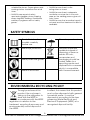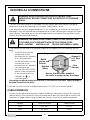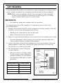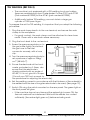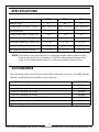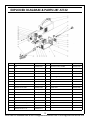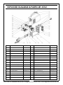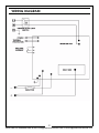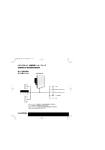
1
WARNING: A suitable welding headshield must be worn during use
WARNING: Read these instructions before using the machine
ARC/TIG WELDER
MODEL NO: AT101, AT132, AT161
PART NO: 6012237, 6012231, 6012250
OPERATION & MAINTENANCE
INSTRUCTIONS
LS0114
INTRODUCTION
Thank you for purchasing this CLARKE ARC/TIG Welder.
Before attempting to operate the machine, it is essential that you read this
manual thoroughly and carefully follow all instructions given. In doing so you
will ensure the safety of yourself and that of others around you, and you can
also look forward to the welder giving you long and satisfactory service.
The ARC/TIG welder, as its name suggests, is designed to be used for both
Metal ARC/ TIG welding. To accomplish this, two sets of welding leads are
required, one for each method employed.
TIG welding leads are not supplied with the machine. These are however
readily available from your CLARKE dealer. For the AT101 and AT132 (Part
number 6012232) for the AT161 (part number 6012233)
GUARANTEE
This CLARKE product is guaranteed against faulty manufacture for a period of
12 months from the date of purchase. Please keep your receipt as proof of
purchase.
This guarantee is invalid if the product is found to have been abused or
tampered with in any way, or not used for the purpose for which it was
intended.
Faulty goods should be returned to their place of purchase, no product can
be returned to us without prior permission.
This guarantee does not effect your statutory rights.
UNPACKING
Any damage or deficiency should be reported to your CLARKE dealer
immediately. you should find inside the following:
• 1 x ARC / TIG Inverter Welder
• 1 x Wire Brush / Hammer
• 1 x Electrode Clamp & Cable
• 1 x Carrying Strap (fitted)
• 1 x Earth Clamp & Cable
• 1 x Instruction Manual
2
Parts & Service: 020 8988 7400 / E-mail: [email protected] or [email protected]
GENERAL SAFETY INSTRUCTIONS
WARNING: WHEN USING ELECTRICAL TOOLS, BASIC SAFETY
PRECAUTIONS SHOULD ALWAYS BE FOLLOWED TO REDUCE THE RISK OF
FIRE, ELECTRIC SHOCK AND PERSONAL INJURY.
WARNING: READ ALL THESE INSTRUCTIONS BEFORE ATTEMPTING TO
OPERATE THIS PRODUCT AND KEEP THESE INSTRUCTIONS IN A SAFE PLACE.
ELECTRIC SHOCK
FUMES & GASES
• Always remove the plug from the
socket and wait 5 minutes to allow the
capacitors to discharge before
carrying out servicing or maintenance.
• The welding process generates
hazardous fumes as a by-product.
Inhalation of these fumes is hazardous
to health.
• Do not touch live electrical parts.
• Keep your head away from the weld to
avoid breathing the fumes.
• Never use electrode holders or cables
which are damaged.
• If welding in confined spaces, ensure
adequate ventilation and use a fume
extractor.
• Keep the working environment,
equipment, cables and clothing free
from grease, oil, moisture and dirt.
• By-products of welding can react to
create a toxic/explosive environment.
• Ensure the welding machine has been
correctly earthed.
FIRE OR EXPLOSION
• The operator must be insulated from the
floor and work bench, using a dry
insulation mat.
Welding can cause fire and explosions.
Precautions should be taken to prevent
these hazards.
• Always ensure a second person is
present in case of accident.
• Before starting work ensure the area is
clear of flammable materials.
• Never change electrodes with bare
hands or damp gloves.
• Move any combustible materials to a
safe distance, especially substances
likely to generate a dangerous vapour.
• Keep welding cables away from power
cables.
• The welding arc can cause serious
burns. Avoid contact with the skin.
• Regularly inspect the condition of the
cables for signs of damage.
• Sparks and molten metal are ejected
during welding. Take precautions to
prevent fire.
• Remove the plug from the mains socket
when not in use, do not leave the
machine unattended.
• Sparks and molten metal can pass
through gaps. Be aware that fire can
start out of sight.
• Ensure the earth clamp is secured to
bare metal adjacent to the weld seam,
and when not in use, is insulated for
safety. - Keep all equipment well
maintained.
• Do not weld pressurised containers. or
containers containing flammable
vapours e.g. fuel tanks.
• The operator shall prevent gas cylinders
in the vicinity of the workpiece from
becoming part of the welding circuit.
• Always have appropriate fire fighting
equipment to hand suitable for use in
electrical environments.
3
Parts & Service: 020 8988 7400 / E-mail: [email protected] or [email protected]
PROTECTIVE CLOTHING
• Avoid carrying any fuels with you e.g.
cigarette lighters or matches.
• Wear gauntlet gloves designed for use
in welding,
PERSONAL PROTECTION
• Wear an apron and protective shoes.
• The body should be protected by
suitable clothing.
• Wear cuffless trousers to avoid entry of
sparks and slag.
• The use of neck protection may be
necessary against reflected radiation.
• Avoid oily, greasy clothing.
• Protective head and shoulder
coverings should be worn when
overhead welding.
• Arc welding machines generate a
magnetic field which is detrimental to
pacemakers. Consult your doctor
before going near active welding
equipment/operations.
• Wear a welding headshield with
appropriate filter lenses or plates
(protected by clear glass). This is a MUST
for welding (and chipping) to protect
the eyes from radiant energy and
splatter. Replace cover glass when
broken, pitted, or splattered.
• The UV and IR radiation generated by
welding is highly damaging to the eyes,
causing burns. This can also affect the
skin.
• Always use a suitable welding shield
equipped with appropriate protective
filters.
NOTE: ALL protective wear inc. masks &
head shields MUST comply with PPE
Directive 89/686/EEC
• Where there are pedestrians and traffic,
ensure a protective screen is used to
avoid accidental arc glare.
ADDITIONAL SAFETY PRECAUTIONS FOR
ARC WELDERS
• Do not weld in the vicinity of children or
animals and ensure no one is looking
before striking an arc.
• NEVER attempt to remove any of the
exterior panels unless the machine is
disconnected from the power supply.
• Wear hearing protection if required.
• NEVER use the machine with any of the
panels removed.
• Allow the weld time to cool. Hot metal
should never be handled without
gloves.
• NEVER attempt any electrical or
mechanical repair unless your are a
qualified technician. If you have a
problem with the machine contact
your local CLARKE dealer.
• Take care when adjusting or
maintaining the torch, make sure it has
had time to cool sufficiently and the
welder is disconnected from the mains
supply.
• NEVER use or store in a wet/damp
environment. DO NOT EXPOSE TO RAIN.
• First aid facilities and a qualified first aid
person should be available unless
medical facilities are close by, for
immediate treatment of flash burns of
the eyes and for skin burns.
• NEVER allow children or animals in the
vicinity of a welding operation.
• ALWAYS remove all flammable materials
from the welding area.
• ALWAYS ensure that there is full free air
circulating around the outer casing of
the machine, and that the louvres are
unobstructed.
• A hard hat should be worn when others
are working overhead.
• Flammable hair sprays/gels should not
be used by persons intending to weld or
cut.
• Welding arc can seriously damage your
eyes. Both the operator and any
spectators should always use a proper
welding face shield or helmet, with
4
Parts & Service: 020 8988 7400 / E-mail: [email protected] or [email protected]
• ALWAYS ensure there is a fire
extinguisher on hand.
suitable filter lenses. Proper gloves and
working clothes should be worn at all
times.
• ALWAYS ensure there is adequate
ventilation or extraction in the work
area, as the welding process gives off
toxic fumes.
• ALWAYS wear a pair of safety
spectacles/goggles when chipping
away slag after welding,. Remember,
ordinary eye glasses are not safety
gasses.
• ALWAYS ensure that a medical supply is
on hand, and that treatment for burns is
available.
SAFETY SYMBOLS
Read this instruction
booklet carefully
before use.
Do not expose to rain.
Wear eye protection
Recycle unwanted
materials instead of
disposing of them as
waste. All tools,
accessories and
packaging should be
sorted, taken to a
recycling centre and
disposed of in a manner
which is compatible
with the environment.
Wear protective gloves
Wear a dust mask
ENVIRONMENTAL RECYCLING POLICY
Through purchase of this
product, the customer is
taking on the obligation to
deal with the WEEE in
accordance with the WEEE
regulations in relation to the
treatment, recycling & recovery and
environmentally sound disposal of
the WEEE.
In effect, this means that this product
must not be disposed of with general
household waste. It must be
disposed of according to the laws
governing Waste Electrical and
Electronic Equipment (WEEE) at a
recognised disposal facility.
5
Parts & Service: 020 8988 7400 / E-mail: [email protected] or [email protected]
ELECTRICAL CONNECTIONS
WARNING: READ THESE ELECTRICAL SAFETY INSTRUCTIONS
THOROUGHLY BEFORE CONNECTING THE PRODUCT TO THE MAINS
SUPPLY.
Connect the mains lead to a standard, 230 Volt (50Hz) electrical supply through an
approved 13 amp BS 1363 plug, or a suitably fused isolator switch.
If the plug has to be changed because it is not suitable for your socket, or because of
damage, it must be removed and a replacement fitted, following the wiring instructions
shown below. The old plug must be discarded safely, as insertion into a power socket
could cause an electrical hazard.
WARNING: THE WIRES IN THE POWER CABLE OF THIS PRODUCT ARE
COLOURED IN ACCORDANCE WITH THE FOLLOWING CODE:
BLUE = NEUTRAL
BROWN = LIVE YELLOW AND GREEN = EARTH
If the colours of the wires in the power cable do not agree with the markings on the
plug.
• The BLUE wire must be
connected to the
terminal which is marked
N or coloured black.
• The BROWN wire must be
connected to the
terminal which is marked
L or coloured red.
Plug must be BS1363/A approved.
Earth
(Green and
Yellow)
Neutral
(Blue)
• The YELLOW AND GREEN
wire must be connected
to the terminal which is
Always fit
a 13 Amp
fuse.
Live
(Brown)
Ensure that the outer sheath of
the cable is firmly held by the clamp
marked E or
or
coloured green.
We strongly recommend that this machine is connected to the mains supply through a
Residual Current Device (RCD)
If you are not sure, consult a qualified electrician. DO NOT try to do any repairs.
CABLE EXTENSION
Always use an approved extension cable suitable for the power rating of this tool (see
specifications), the conductor size should also be at least the same size as that on the
machine, or larger. When using a cable reel, always unwind the cable completely.
If a cable extension is needed it is essential to comply with the following data.
Voltage
Extension length
Cable section
230V
up to 20 m
2.5 mm2
230V
20 - 50 m
4 mm2
6
ARC WELDING
A consumable electrode is connected to a high ampage low voltage supply
which creates an electric arc between the electrode and the workpiece.
NOTE: When using the welder outside, you may need to take measures
to erect a wind break to make sure the shielding gas is not blown
away, thereby leaving a poor quality weld.
PREPARATION
• Arc welding cables are supplied with this machine.
To prepare the unit for ARC welding, it is important that you follow the
procedure below.
1. Making sure that the ON/OFF switch, located on the rear panel is in the OFF
position, connect the welding leads as follows:
• Welding rod holder lead to the +ve terminal.
• Work clamp lead to the -ve terminal.
2. Select the appropriate welding rod and insert it into the welding rod holder.
• The size (diameter) of the welding rod should be approximately the
same as the thickness of metal to be welded.
3. Attach the work clamp to the workpiece as close as possible to the area
being welded. Clean with a wire brush where necessary to ensure the
connection is as clean as possible.
4. Set the required current using the
current selector.
• With practice you will gain a feel
for the correct current setting for
different welding rod thicknesses.
• The following table gives a useful
guideline.
Welding Rod Size
Current (Amps)
1.5 mm
30-40
2.0 mm
50 - 65
2.5 mm
70 - 100
3.0 mm
100 - 125
Fig 1
7
Parts & Service: 020 8988 7400 / E-mail: [email protected] or [email protected]
5. Switch ON using the switch located on the rear panel.
• The green light on the front panel should glow, indicating the machine is
ON.
• If the machine stops at any time and the amber light comes ON, the
thermal overload device has intervened. Wait until the welder has
cooled sufficiently (the amber light goes out) before restarting work.
STRIKING THE ARC - WELDING
WARNING: WHEN WELDING ALWAYS ENSURE THERE IS ADEQUATE
VENTILATION IN THE WORK AREA AS THE WELDING PROCESS GIVES OFF
TOXIC FUMES.
WARNING: ALWAYS USE A SUITABLE WELDING MASK OR SHIELD WHEN
USING ANY WELDER.
The most difficult aspect of the arc welding process, particularly for beginners,
is that of striking an arc. We strongly recommend that you practice on some
pieces of scrap metal to get the feel of the operation, before you start on an
actual welding job.
1. Hold the electrode about 10 mm from the work and at an angle of about
70° to 80° to the work surface; take care not to accidentally touch the
workpiece until you are ready to start.
2. Holding the welding mask close-up to your face, give a short stroke with
the electrode on the workpiece. As soon as the arc is primed, withdraw the
electrode from the workpiece to leave a tiny gap of around 1.5mm (1/16").
The current will flow across the gap with a crackling noise and a brilliant
arc. Continue to weld in one direction, maintaining the small gap as you
go.
NOTE: When you prime the arc, be sure to withdraw the electrode swiftly
to leave the 1.5 mm. gap, otherwise the electrode will weld itself
to the workpiece. If this occurs give the electrode a short sharp
jerk to free it and, if necessary, prime the arc again. If you cannot
free the electrode, switch the machine off immediately and free
it. Take care the electrode will get red hot very quickly and will be
capable of burning through welding gloves.
3. At the end of the run, just lift the electrode away from the workpiece.
• Inspect the job carefully. Any slag forming on the surface should be
chipped away with a chipping hammer or pick. ALWAYS wear your
safety goggles when chipping away slag.
8
Parts & Service: 020 8988 7400 / E-mail: [email protected] or [email protected]
TIG WELDING
TIG welding is primarily for very thin materials. It uses a non-consumable
tungsten (or tungsten alloy) electrode, held in a torch.
A shielding gas (100% Argon), is fed through the torch to protect:
• The electrode,
• Molten weld pool,
• Solidifying weld metal from contamination by the atmosphere.
The electric arc is produced by the passage of current through the
conductive, ionized shielding gas. The arc is established between the tip of the
electrode and the work. Heat generated by the arc melts the base metal.
Once the arc and weld pool are established, the torch is moved along the
joint and the arc progressively melts the joined surfaces. Filler wire, if used, is
usually added to the leading edge of the weld pool to fill the joint.
This process is ideally suited for welding thin metals such as car body panels,
pressure vessels, heat exchangers, pipes etc., where accuracy and a high
quality weld is desired, as it produces a very low porosity weld.
MAIN FEATURES OF TIG WELDING
1. Electronic control of welding current.
2. Forced air cooling.
3. A thermal overload protection device prevents overheating.
TIG WELDING PROCESS ADVANTAGES
• It produces superior quality welds, generally free of defects.
• It is free of the spatter which occurs with other arc welding processes.
• It can be used with or without filler metal as required.
• It allows excellent control of root pass weld penetration.
• It can produce welds at high speeds.
• It allows precise control of the welding variables.
• Capable of welding very thin material (0.5mm), without undue
distortion.
LIMITATIONS
1. Greater weld dexterity is required.
2. These units have a DC output which is not suitable for welding aluminium.
9
Parts & Service: 020 8988 7400 / E-mail: [email protected] or [email protected]
TIG WELDING (REF FIG.2)
• The machine is not equipped with a TIG welding torch and cables;
these are available from your Clarke dealer. For the AT101 and AT132
(Part number 6012232) for the AT161 (part number 6012233).
• Additionally, before TIG welding, you must obtain a large gas
cylinder of 100% pure Argon.
To prepare the unit for TIG welding, it is important that you adopt the following
procedure.
1. Plug the work clamp lead in to the +ve terminal, and secure the work
clamp to the workpiece.
• For good contact, the work clamp must be attached to clean bare
metal. Clean with a wire brush where necessary.
2. Plug the torch lead to the -ve terminal.
3. Screw the pressure regulator on to
the gas bottle tightly, and attach
the gas hose to the inlet
connector securely, with a hose
clip.
Fig 2
4. Turn the pressure regulator knob to
set a pressure of approx. 2.5kg/
cm2. (35 lbf/in2).
5. Ensure the electrode at the torch
nozzle, protrudes by 4 - 5mm, also
ensure that the electrode is
sharply pointed with an angle of
40°-60°, if it is not, grind it to shape.
(Consult your TIG Torch manual for
the procedure for adjusting the electrode).
6. Set the welding current in accordance with the thickness of the material to
be welded and the size of tungsten electrode to be used, (See page 12),
7. Switch ON using the switch mounted on the rear panel. The green light on
the front panel will glow.
• If the machine stops at any time and the amber light comes ON, the
thermal overload has intervened. Wait until the welder has cooled
sufficiently (the amber light goes out) before restarting work.
10
Parts & Service: 020 8988 7400 / E-mail: [email protected] or [email protected]
8. Open the gas valve on the torch handle,
• This will allow gas to flow from the torch nozzle.
9. Cover your face with the head shield, bring the torch to within 3-4mm of
the work, and at an angle of 45°, so that the ceramic nozzle gently touches
the work surface. See fig. 3.
Fig 3
10. Scratch the tip of the electrode on soon as an arc develops, quickly
withdraw the electrode to maintain a gap of approx. 3-4 mm, and
proceed to weld. (See notes below).
• This method is referred to as ‘Scratch Arc’.
11. To stop welding, simply remove the torch from the workpiece.
12. Turn OFF the gas as soon as you finish welding.
NOTE:
• To avoid a visible strike mark on the surface of the workpiece, it is
advisable to strike the arc in the joint, where the mark will be
concealed by the weld.
• Thin sheet and stainless steel may be welded with or without filler,
similar to gas welding.
• The filler is fed in at the edge of the pool. The rod must not touch the
tip of the electrode or enter the arc. The end of the rod must always
be shielded by the argon atmosphere to prevent as far as possible
the formation of oxides of its surface. When welding stainless steel
and copper, it is often possible to feed in the filler continuously at
the edge of the pool.
• The arc length generally varies between 3 and 6 mm depending on
the type of joint, type and thickness of material, and so on.
• The torch is advanced in the direction of welding, without lateral
movement, maintaining the torch angle of 45o to the workpiece.
11
Parts & Service: 020 8988 7400 / E-mail: [email protected] or [email protected]
Guidelines for the TIG welding current needed and recommended electrode
sizes etc. for different gauges of material are shown in the chart below:
Metal
Welding
Current
(Amps)
Workpiece
Thickness
(mm)
Filler Rod
Dia (mm)
Welding
Electrode
Dia (mm)
Gas Flow
ltr/min
Mild Steel
30
1
0-2
1.6
4
70
2
2.0
1.6
4
115
3
2.4
2.4
4.3
125
3.5
2.4
2.4
4.6
35
1
0-2
1.6
4
80
2
2.4
2.4
4.3
Stainless
Steel
Copper
125
3
2.4
2.4
4.6
80
2
2.4
2.4
5
125
3
3.2
2.4
5
12
Parts & Service: 020 8988 7400 / E-mail: [email protected] or [email protected]
WELDING PITFALLS
The arc welding technique is an acquired skill and requires considerable
practice before perfect results are obtained. The diagrams below will help to
explain the pitfalls in your technique and how to overcome them.
ARC TOO SHORT
This causes irregular masses of weld to be deposited, with
slag contamination on an uneven surface.
ARC TOO LONG
This causes poor penetration resulting in a weak weld with
excessive spatter and porosity. Surface of the weld is rough
and the arc makes a hissing sound
ELECTRODE MOVED TOO SLOWLY
This causes a very wide and heavy deposit which overlaps
at the sides. It is wasteful both in terms of time and electrode
use.
ELECTRODE MOVED TOO QUICKLY
This causes poor penetration with a ‘stringy’ and incomplete
weld deposit. Slag is very hard to remove.
CURRENT TOO LOW
This causes poor penetration and causes the electrode to
stick to the workpiece too readily. Also results in a very
irregular and high weld deposit. Slag is very hard to remove.
CURRENT TOO HIGH
This causes excessive penetration with spatter and deep
pointed crater. It may also cause holes to be burned in the
workpiece.
Burns electrodes very quickly.
THE PERFECT WELD
With the correct combination of arc length, current
regulation, inclination and speed of the electrode, you will,
with practice, produce the perfect weld.
This should be regular with uniform ripples and no slag
contamination. The arc will make a steady crackling sound.
13
Parts & Service: 020 8988 7400 / E-mail: [email protected] or [email protected]
TROUBLESHOOTING
DEFECT
CAUSES
SUGGESTIONS
Spark will not start
Bad clamp connection.
Inverter printed circuit is
defective.
Check clamp connection.
Contact your nearest
CLARKE dealer.
No output voltage Overheated machine (the
yellow LED should be on).
Wait for thermal cutout to
be reset.
Under-voltage/over-voltage Check the mains distribution
limits exceeded. Yellow LED system.
on and green LED flashing. Wait for internal check of
input voltage.When this is
within normal limits, the
yellow LED will go out and
the green LED will stay on.
Internal relay has failed.
Contact your nearest
CLARKE dealer.
Inverter printed circuit is
defective.
Contact your nearest
CLARKE dealer.
Current selector control is
defective.
Contact your nearest
CLARKE dealer.
Low power supply voltage.
Check the mains distribution
system.
Porosity of welds
Acid electrode on steel
with high sulphur content.
Electrode oscillates too
much.
Workpieces are too far
apart.
Workpiece being welded is
cold.
Use basic electrode.
Move edges to be welded
closer together. Move slowly
at the beginning.
Cracks in weld
Material being welded is
dirty (e.g.oil, paint, rust,
oxides).
Not enough current.
Clean workpiece before
welding is an essential
method of achieving neat
weld beads.
Limited
penetration
Low current, high welding
rate, reversed polarity.
Electrode inclined in
position opposite to it's
movement.
Ensure operating para meters are regulated and
improve preparation of
work pieces.
Wrong output
current
14
Parts & Service: 020 8988 7400 / E-mail: [email protected] or [email protected]
DEFECT
CAUSES
SUGGESTIONS
High Sprays
Electrode is too inclined.
Make appropriate
corrections.
Profile defects.
Welding parameters are
incorrect.
Pass rate is not related to
operating parameter
requirements.
Electrode not inclined
constantly while welding.
Follow basic and general
welding principles.
Arc is unstable.
Insufficient current.
Check condition of
electrode and earth wire
connection.
Electrode melts
obliquely.
Electrode core is not
centred.
Magnetic blow
phenomenon.
Replace electrode.
Connect two earth wires
to opposite sites of the
work piece.
MAINTENANCE
The ARC/TIG Inverter, requires very little maintenance other than the following
guidelines. Under normal working conditions removing the covers and
cleaning with dry compressed air at reduced pressure once a year will be
quite sufficient. Cleaning at more frequent intervals is advisable however, if the
unit is operating in a dusty and dirty environment.
1. Keep the louvres clean to avoid a build up of dirt and oxides inside the
machine, which can reduce machine output.
2. Check all cables periodically for condition and security: They must be in
good condition and not cracked.
3. Always avoid getting particles of metal inside the machine since they
could cause short circuits.
IMPORTANT: Disconnect from mains before cleaning.
DO NOT attempt to carry out repairs yourself, unless you are fully competent,
all work must be carried out by a qualified technician.
15
Parts & Service: 020 8988 7400 / E-mail: [email protected] or [email protected]
RATING PLATE
AT101 SHOWN
AS AN EXAMPLE
1
Name and address of manufacturer
12
Rated Welding Current Symbol
2
Model Number, / Part Number
13
Conventional Load Voltage Symbol
3
Serial / Batch Number
14
Energy Supply Symbol
4
Welding Power Source
15
Rated Supply Voltage
5
British Standards applied
16
Rated Maximum Supply Current
6
Welding Process Symbol
17
Maximum Effective Supply Current
7
This symbol indicates that the unit is
suitable for carrying out welding
operations in an environment which
has an increased risk of electric
shock.
18
N/A
8
Welding Current Symbol
19
N/A
9
Rated No-load Voltage
20
N/A
10
Range Of Output
21
N/A
11
Duty Cycle Symbol
22
Degree of Protection
DUTY CYCLE
This welder is covered by regulations EN60974-1 and EN 50199, where the Duty
Cycle (X) is expressed as a percentage of time the machine may be used in a
given period for a specified welding current.
i.e. When welding at 65 Amps the machine may be used for 6 minutes (60%) in
any10 minute period,
16
Parts & Service: 020 8988 7400 / E-mail: [email protected] or [email protected]
SPECIFICATIONS
AT101
AT132
AT161
5.1
6.6
7.7
280 x 120 x 176
332 x 140 x 185
340 x 146 x 231
230V ~ 50Hz
230V ~ 50Hz
230V ~ 50Hz
10.4
18.3
24.1
64
64
78
10 - 80
10 - 130
10 - 160
IP21
IP21
IP21
1.6 - 2.5
1.6 - 3.2
1.6 - 4.0
Weight (kg)
Dimensions (l x W x h) (mm)
Power Supply
Rated Max Input Current (A)
Open Circuit Voltage (V)
Max/Min Welding Current (A)
Protection Class
Suitable Electrodes (mm)
NOTE: The details and specifications contained herein, are correct at the
time of going to print. However, CLARKE International reserve the
right to change specifications at any time without prior notice.
ACCESSORIES
The following are some of the accessories available from your CLARKE dealer.
Please quote the part numbers shown below:
DESCRIPTION
PART NUMBER
CWH6 Arc Activated Welding Headshield
6000671
2 mm Arc Welding Electrodes
3050555
2.5 mm Arc Welding Electrodes
3050560
3.2 mm Arc Welding Electrodes
3050565
TIG Welding Torch Assembly (AT101, AT132)
6012232
TIG Welding Torch Assembly (AT161)
6012233
Argon Gas Regulator
8134140
17
Parts & Service: 020 8988 7400 / E-mail: [email protected] or [email protected]
EXPLODED DIAGRAM & PARTS LIST AT101
NO
DESCRIPTION
PART NO
NO
DESCRIPTION
PART NO
1
Belt
SWAT10101
17
Quick Connector
SWAT10117
2
Steel Cover
SWAT10102
18
Heat Sink for F.R.D.
SWAT10118
3
IGBT
SWAT10103
19
Fast Recovery Diode
SWAT10119
4
Main Cable
SWAT10104
20
Temperature Controller
SWAT10120
5
Switch
SWAT10105
21
Electrode Holder
SWAT10121
6
Cable Clip
SWAT10106
22
Earth Clamp
SWAT10122
7
Fan Cover
SWAT10107
23
LED Cover
SWAT10123
8
Bridge
SWAT10108
24
Potentiometer Knob
SWAT10124
9
Heat Sink for IGBT
SWAT10109
25
PCB
SWAT10125
10
IGBT
SWAT10110
26
Inductance
SWAT10126
11
Fast Recovery Diode
SWAT10111
27
Yellow LED
SWAT10127
12
Fan
SWAT10112
28
Green LED
SWAT10128
13
Heat Sink for IGBT
SWAT10113
29
Potentiometer
SWAT10129
14
4.2 x 9.5 Screw
SWAT10114
30
Transformer
SWAT10130
15
Steel Base
SWAT10115
31
Control PCB
SWAT10131
16
Capacitor
SWAT10116
32
Insulating Clapboard
SWAT10132
18
Parts & Service: 020 8988 7400 / E-mail: [email protected] or [email protected]
EXPLODED DIAGRAM & PARTS LIST AT132
NO
DESCRIPTION
PART NO
NO
DESCRIPTION
PART NO
1
Belt
SWAT13201
18
Fast Recovery Diode
SWAT13218
2
Steel Cover
SWAT13202
19
Temperature Controller
SWAT13219
3
IGBT
SWAT13203
20
Electrode Holder
SWAT13220
4
Switch
SWAT13204
21
Earth Clamp
SWAT13221
5
Main Cable
SWAT13205
22
Insulating Clapboard
SWAT13222
6
Cable Clip
SWAT13206
23
Potentiometer Knob
SWAT13223
7
Fan Cover
SWAT13207
24
LED Cover
SWAT13224
8
IGBT IKW40N60H3
SWAT13208
25
Yellow LED
SWAT13225
9
Heat Sink for IGBT
SWAT13209
26
Green LED
SWAT13226
10
Fast Recovery Diode
SWAT13210
27
Inductance
SWAT13227
11
Heat Sink for IGBT
SWAT13211
28
Potentiometer
SWAT13228
12
Fan
SWAT13212
29
Transformer
SWAT13229
13
4.2x9.5 ST Screw
SWAT13213
30
Control PCB
SWAT13230
14
Steel Base
SWAT13214
31
Capacitor
SWAT13231
15
Heat Sink for Bridge
SWAT13215
32
Bridge
SWAT13232
16
Quick Connector
SWAT13216
33
PCB
SWAT13233
17
Heat Sink for F.R.D.
SWAT13217
19
Parts & Service: 020 8988 7400 / E-mail: [email protected] or [email protected]
EXPLODED DIAGRAM & PARTS LIST AT161
NO
DESCRIPTION
PART NO
NO
DESCRIPTION
PART NO
1
Belt
SWAT16101
18
Fast Recovery Diode
SWAT16118
2
Steel Cover
SWAT16102
19
Temperature Controller
SWAT16119
3
IGBT
SWAT16103
20
Electrode Holder
SWAT16120
4
Switch
SWAT16104
21
Earth Clamp
SWAT16121
5
Main Cable
SWAT16105
22
Inductance
SWAT16122
6
Cable Clip
SWAT16106
23
LED Cover
SWAT16123
7
Fan Cover
SWAT16107
24
Potentiometer Knob
SWAT16124
8
IGBT
SWAT16108
25
Yellow LED
SWAT16125
9
Fast Recovery Diode
SWAT16109
26
Green LED
SWAT16126
10
Heat Sink for IGBT
SWAT16110
27
Control PCB
SWAT16127
11
Heat Sink for IGBT
SWAT16111
28
Potentiometer
SWAT16128
12
Fan
SWAT16112
29
Transformer
SWAT16129
13
4.2 x 9.5 Screw
SWAR16113
30
PFC Control PCB
SWAT16130
14
Feet
SWAT16114
31
Heat Sink for Bridge
SWAT16131
15
Steel Base
SWAT16115
32
Bridge
SWAT16132
16
Heat Sink for F.R.D
SWAT16116
33
Capacitor
SWAT16133
17
Quick Connector
SWAT16117
34
PCB
SWAT16134
20
Parts & Service: 020 8988 7400 / E-mail: [email protected] or [email protected]
WIRING DIAGRAM
21
Parts & Service: 020 8988 7400 / E-mail: [email protected] or [email protected]
DECLARATION OF CONFORMITY
22
Parts & Service: 020 8988 7400 / E-mail: [email protected] or [email protected]
ALSO AVAILABLE FROM YOUR CLARKE DEALER
WELDING ELECTRODES
ARC ACTIVATED HEADSHIELD
Part Numbers
Part Number
• 2mm Electrodes (3050555)
• CWH6 Arc Activated Headshield
(6000671)
• 2.5mm Electrodes (3050560)
• 3.2mm Electrodes (3050565)
TIG WELDING TORCH KITS
ARGON GAS & GAS REGULATOR
Part Numbers
Part Numbers
• AT101/AT132 TIG Welding Torch Kit
(6012232)
• Argon Gas Regulator (8134140)
• AT161 TIG Welding Torch Kit
(6012233)
23
Parts & Service: 020 8988 7400 / E-mail: [email protected] or [email protected]