1
MicroSCADA Pro
SYS 600 9.2
Installation and Administration Manual
1MRS756115
MicroSCADA Pro
Issued: 30.10.2007
Version: B/30.10.2007
Installation and Administration Manual
SYS 600 9.2
Contents
Copyrights ................................................................................. 7
1. Introduction..............................................................9
1.1.
1.2.
1.3.
1.4.
1.5.
1.6.
This manual.............................................................. 9
Use of symbols ......................................................... 9
Intended audience ..................................................... 9
Product documentation ............................................. 10
Document conventions ............................................. 10
Document revisions...................................................11
2. Installation ............................................................. 13
2.1. Installing system servers ...........................................
2.1.1. Hardware requirements.................................
2.1.2. Software requirements ..................................
2.1.3. Installation procedure ...................................
2.1.4. Installing SYS 600 .......................................
2.1.5. Verifying SYS 600 installation ........................
2.2. Local Area Network (LAN).........................................
2.2.1. Network interface card ..................................
2.2.2. IP addresses...............................................
2.2.3. Host names ................................................
2.2.4. Configuring SYS 600 for LAN ........................
2.2.5. Verifying the LAN communication ...................
2.3. Installing workplaces ................................................
2.3.1. Installing Terminal Services ...........................
2.3.2. Terminal Server system requirements..............
2.3.3. Licensing service installation..........................
2.3.4. Installing Windows 2000/2003 Terminal
Services .....................................................
2.3.5. Installing Terminal Server Client .....................
2.3.6. Remote Display Protocol (RDP) Client ............
2.4. Citrix MetaFrame Application Server ...........................
2.4.1. Introduction.................................................
2.4.2. System requirements....................................
2.4.3. Installing Citrix MetaFrame Presentation
Server 4.0 system........................................
2.4.3.1. Windows components installation .....
2.4.3.2. Get Citrix license file from internet....
2.4.3.3. Installation and configuration of
MetaFrame Access Suite licensing ...
2.4.3.4. Install MetaFrame Presentation
Server 4.0 and its components ........
2.4.4. Publishing applications .................................
2.5. ICA Workstation Installation ......................................
13
13
14
14
15
19
25
25
25
26
26
27
27
27
29
30
32
35
36
37
37
38
38
38
39
40
44
49
56
3
SYS 600 9.2
MicroSCADA Pro
1MRS756115
Installation and Administration Manual
2.5.1.
Installation of “Program Neighborhood”-Client...
2.5.2.
Adding a new Application Set .......................
2.6. Installing process communication units ........................
2.6.1. PC-NET process communication unit ..............
2.6.1.1. Installing multiport serial card ..........
2.6.1.2. Installing LON cards ......................
2.6.1.3. Installing network cards ..................
2.6.1.4. Verifying PC-NET process
communication unit ........................
2.6.2. IEC 61850 ..................................................
2.7. Installing peripheral equipment ...................................
2.7.1. Installing printers .........................................
2.7.1.1. Connecting printers to the base
system.........................................
2.7.1.2. Connecting printers to LAN .............
2.7.1.3. Connecting printers to PC-NET
units............................................
2.7.2. Installing adapter cards.................................
2.8. Installing SYS 600 Application OPC Server..................
56
57
64
64
64
65
65
66
67
67
67
67
68
69
72
73
3. System administration............................................. 75
3.1. Transferring objects.................................................. 75
3.1.1. Opening and exiting Export/Import tool ............ 76
3.1.2. Exporting objects ......................................... 77
3.1.2.1. Exporting formats .......................... 79
3.1.2.2. Defining CSV attributes .................. 79
3.1.2.3. Defining common options for
exported data ............................... 83
3.1.3. Importing objects ......................................... 85
3.1.3.1. Defining common options for
imported data ............................... 87
3.2. Searching strings ..................................................... 88
3.2.1. Opening and exiting Search tool..................... 88
3.2.2. Making searches ......................................... 90
3.2.3. Defining searches ........................................ 91
3.2.4. Saving searches .......................................... 94
3.2.5. Analyzing search results ............................... 95
3.3. SCIL Database Tool ................................................. 96
3.3.1. Opening the SCIL Database File .................... 97
3.3.2. Creating a New SCIL Database File ............... 99
3.3.3. Creating New Section with Value...................100
3.3.4. Editing Section Value ..................................101
3.3.5. Saving SCIL Database File ..........................101
3.3.6. Renaming Sections .....................................102
4
1MRS756115
MicroSCADA Pro
SYS 600 9.2
Installation and Administration Manual
3.3.7.
3.3.8.
3.4.
3.5.
3.6.
3.7.
Deleting Selected Content ............................102
Transferring information between two SCIL
Database Tools ..........................................103
Hard disk management............................................103
3.4.1. Using Disk Management tool ........................104
3.4.1.1. Activating automatic disk space
settings.......................................106
3.4.1.2. Creating new file sets....................107
3.4.1.3. Deleting file sets...........................108
3.4.1.4. Defining file set properties..............108
3.4.1.5. Viewing execution messages.......... 110
3.4.1.6. Viewing log ................................. 110
Starting SYS 600 .................................................... 112
3.5.1. Starting base systems ................................. 112
3.5.2. Base System startup procedures ................... 112
3.5.3. Application startup procedures ...................... 112
3.5.4. Manual startup of SYS 600 Monitor ............... 113
3.5.5. Defining automatic startup for SYS 600 .......... 114
3.5.6. Opening SYS 600 Monitor manually .............. 114
3.5.7. Automatic logon of SYS 600......................... 116
3.5.8. Automatically opened MicroSCADA monitors... 117
3.5.9. Defining customized icon for SYS 600
monitors .................................................... 119
3.5.10. Automatic opening at application startup.........120
3.5.11. Automatically opened MicroSCADA monitor at
user logon .................................................120
3.5.12. Starting base systems from command line ......122
3.5.13. Starting PC-NET.........................................123
3.5.14. Shutting down SYS 600 ...............................125
3.5.15. Backup files ...............................................126
3.5.15.1. Creating online backup..................127
3.5.15.2. Configuring Backup Tool ................129
3.5.15.3. Testing new configuration...............131
3.5.16. Uninstalling MicroSCADA .............................131
Verifying SYS 600 startup ........................................133
SYS 600 Monitor Pro Remote Connection ..................137
4. Upgrading from earlier revisions ............................ 141
4.1. Base system ..........................................................141
4.1.1. Mirroring considerations ...............................142
4.1.2. Upgrading from revision 8.4.5 SP1 or 9.0 .......143
4.1.3. Upgrading from revision 8.4.3 .......................143
4.1.4. Upgrading from revision 8.4.2 .......................144
4.1.5. Upgrading from revision 8.4.1 .......................145
4.1.6. Upgrading from revision 8.4.0 .......................146
5
SYS 600 9.2
MicroSCADA Pro
1MRS756115
Installation and Administration Manual
4.2.
4.3.
4.4.
4.5.
4.6.
4.1.7. Upgrading from revision 8.2..........................146
4.1.8. Upgrading from revision 8.1..........................146
LIB 5xx .................................................................147
Monitor Pro............................................................148
4.3.1. Common applications with LIB 5xx ................148
Communication units ...............................................150
4.4.1. PC-NET ....................................................151
4.4.1.1. PC-NET from SYS 600 9.1 (COM
500 4.2) ......................................151
4.4.1.2. PC-NET from SYS 500 8.4.x ..........152
4.4.1.3. PC-NET from SYS 500 8.x ............153
4.4.2. IEC 61850 .................................................153
4.4.3. Modbus slave.............................................154
4.4.4. CDC-II slave ..............................................154
4.4.5. External OPC Data Access Client..................154
Communication gateway ..........................................154
4.5.1. Upgrading COM 500 revision 2.0, 3.0, 4.0, 4.1
and 4.2 .....................................................154
4.5.2. Upgrading COM 500i revision 1.0 ..................155
Updating device drivers ...........................................155
5. Abbreviations ....................................................... 157
6
1MRS756115
MicroSCADA Pro
SYS 600 9.2
Installation and Administration Manual
Copyrights
The information in this document is subject to change without notice and should not
be construed as a commitment by ABB Oy. ABB Oy assumes no responsibility for
any errors that may appear in this document.
In no event shall ABB Oy be liable for direct, indirect, special, incidental or
consequential damages of any nature or kind arising from the use of this document,
nor shall ABB Oy be liable for incidental or consequential damages arising from
use of any software or hardware described in this document.
This document and parts thereof must not be reproduced or copied without written
permission from ABB Oy, and the contents thereof must not be imparted to a third
party nor used for any unauthorized purpose.
The software or hardware described in this document is furnished under a license
and may be used, copied, or disclosed only in accordance with the terms of such
license.
© Copyright 2007 ABB. All rights reserved.
Trademarks
ABB is a registered trademark of ABB Group. All other brand or product names
mentioned in this document may be trademarks or registered trademarks of their
respective holders.
Guarantee
Please inquire about the terms of guarantee from your nearest ABB representative.
7
8
1MRS756115
MicroSCADA Pro
SYS 600 9.2
Installation and Administration Manual
1.
Introduction
1.1.
This manual
This manual provides thorough information on the SYS 600 software and hardware
installation: base systems, LAN connections, process communication systems,
workplaces and peripherals.
1.2.
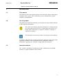
Use of symbols
This publication includes the following icons that point out safety-related conditions
or other important information:
The caution icon indicates important information or warning related to
the concept discussed in the text. It might indicate the presence of a
hazard which could result in corruption of software or damage to
equipment or property.
The information icon alerts the reader to relevant facts and conditions.
It should be understood that operation of damaged equipment could, under certain
operational conditions, result in degraded process performance leading to
information or property loss. Therefore, comply fully with all notices.
1.3.
Intended audience
This manual is intended for installation personnel, administrators and skilled
operators to support installation of the software.
9
MicroSCADA Pro
SYS 600 9.2
1MRS756115
Installation and Administration Manual
1.4.
Product documentation
Name of the document
Document ID
SYS 600 Connecting LONWORKS Devices
1MRS756154
SYS 600 IEC 61850 System Design
1MRS756119
SYS 600 Status Codes
1MRS756178
SYS 600 System Configuration
1MRS756112
SYS 600 System Objects
1MRS756177
SYS 600 OPC Server
1MRS756174
LIB 500 *4.2. Operation Manual
1MRS755359
LIB 500 *4.2. Configuration Manual
1MRS755360
SYS 600 Programming Language SCIL
1MRS756176
SYS 600 CDC-II Slave Protocol
1MRS756188
SYS 600 External OPC Data Access Client
1MRS756163
SYS 600 Communication Gateway, COM 500i User's 1MRS756157
Guide
RER 111 Technical Reference Manual
1MRS750104-MUM
Other related documents:
*
*
*
*
*
*
*
1.5.
Citrix documentation
LONWORKS PCLTA-20 PCI LonTalk Adapter, User's Guide
Microsoft Windows documentation
Product documentation of the used multiport serial card
Product documentation of the used network adapter card
Product documentation of the used PCLTA-10 card
RTU documentation
Document conventions
The following conventions are used for the presentation of material:
*
*
*
*
*
*
*
*
10
The words in names of screen elements (for example, the title in the title bar of a
dialog, the label for a field of a dialog box) are initially capitalized.
Capital letters are used for the name of a keyboard key if it is labeled on the
keyboard. For example, press the CTRL key. Although the Enter and Shift keys
are not labeled they are written in capital letters, e.g. press ENTER.
Lowercase letters are used for the name of a keyboard key that is not labeled on
the keyboard. For example, the space bar, comma key and so on.
Press CTRL+C indicates that you must hold down the CTRL key while pressing
the C key (to copy a selected object in this case).
Press ALT E C indicates that you press and release each key in sequence (to copy
a selected object in this case).
The names of push and toggle buttons are boldfaced. For example, click OK.
The names of menus and menu items are boldfaced. For example, the File menu.
The following convention is used for menu operations: Menu Name > Menu
Item > Cascaded Menu Item. For example: select File > Open > New Project.
1MRS756115
MicroSCADA Pro
SYS 600 9.2
Installation and Administration Manual
*
*
The Start menu name always refers to the Start menu on the Windows Task Bar.
System prompts/messages and user responses/input are shown in the Courier
font. For example, if you enter a value out of range, the following message is
displayed: Entered value is not valid.
You may be told to enter the string MIF349 in a field. The string is shown as
follows in the procedure: MIF349
*
1.6.
Variables are shown using lowercase letters: sequence name
Document revisions
Version
Software revision
number
Date
History
A
9.2
27.07.2007
Document created
B
9.2
30.10.2007
Document updated
11
12
1MRS756115
MicroSCADA Pro
SYS 600 9.2
Installation and Administration Manual
2.
Installation
2.1.
Installing system servers
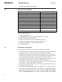
2.1.1.
Hardware requirements
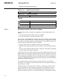
The MicroSCADA Pro base system sets the following minimum configuration
requirements. Follow Microsoft’s recommendations for supported operating
systems, Windows XP, Windows 2000, Windows Server 2003 as shown in the Table
below.
Table 2.1.1.-1
Hardware requirements
Operating System
Hardware
Available Disk minimum
Memory
Windows XP
2 GHz
20 GB
2 GB
Windows 2003 Server
2 GHz
20 GB
2 GB
Windows 2000
2 GHz
20 GB
2 GB
Other hardware requirements:
*
*
*
*
*
*
*
*
*
*
Echelon PCLTA-20 LON adapter requires one PCI-bus slot. One card supports
one LON channel. XLON PCI from DH Electronics takes also one slot per
channel. Adlink PCI-1760 or Nudaq PCI-7250 or PCI-7256 I/O cards require
one PCI slot.
Depending on the size of the application, MicroSCADA Pro requires
approximately 100 to 500 MB of disk space. The recommended total disk
capacity is at least 2GB. Any SCSI or IDE controller or RAID configuration
supported by Windows operating system can be used.
The recommended RAM size is 512 MB or more.
If the base system computer is also used as an operator's workplace, the screen
resolution should be at least 1024x768 pixels. The graphics adapter should
support at least a 256 color mode or a true color mode. To ensure high
ergonomics, the refresh rate of the screen should be at least 70 Hz for CRTscreens.
Any keyboard and mouse supported by Windows can be used.
A CD-ROM device is recommended for Windows installation.
A parallel port can be used for connecting a printer.
Any Ethernet adapter supported by Windows can be used for connecting the base
system computer to the LAN.
A PC 31/32 radio clock board from Meinberg Funkuhren, Germany, can be used
for synchronizing the clock. The board contains a radio receiver for the Frankfurt
DCF-77 77 kHz radio transmitter. Optionally the PC 32 board can be connected
with a serial line to a GPS receiver.
The Comtrol RocketPort multi-port serial communication board can be used to
provide the PC-NET with up to 8 COM ports. Moxa and Digi serial port adapters
are tested as well.
13
MicroSCADA Pro
SYS 600 9.2
1MRS756115
Installation and Administration Manual
2.1.2.
Software requirements
The MicroSCADA Pro system supports the following operating systems:
*
*
*
*
Microsoft Windows 2000 Professional
Windows 2000 Server
Microsoft Windows XP Professional or
Microsoft Server 2003 Standard Edition.
Other server versions might be compatible with MicroSCADA; however those are
not supported by this software.
For more information about operating systems, refer to Microsoft documentation.
The user documentation is available as PDF files on
www.abb.com/microscada, both as part of the product package and as separate files.
Adobe Acrobat Reader is not supplied with MicroSCADA Pro, but can
be downloaded for free from
http://www.adobe.com/products/acrobat/readstep2.html
MicroSCADA Pro supports only the 32-bit version of the operating system.
Additional software
The Hummingbird eXceed version 7.0 or newer is required as an X-server on the
workstation computer whenever the system includes distributed HSI (Human
System Interface), and uses MicroSCADA X and VS Remote monitor types (Classic
workplaces).
2.1.3.
Installation procedure
The MicroSCADA Pro base system installation procedure:
*
*
*
*
*
*
*
*
*
14
Install the network adapter card if a local area network is to be used.
Install the operating system.
Install corresponding device drivers and protocols for the local area network.
Install the PC cards used by MicroSCADA Pro: PC-NET cards, I/O units, LON
adapter cards and radio clock cards.
Install the X-server software, Exceed, if MicroSCADA Pro X-monitors or VS
remote monitors are shown on the base system computer display.
Install the MicroSCADA Pro base product software.
Install optional products, if used: LIB 500 and LIB 5xx.
Add and prepare applications.
Configure, test and start the possible drivers.
1MRS756115
MicroSCADA Pro
SYS 600 9.2
Installation and Administration Manual
*
*
2.1.4.
Modify the base system configuration files to match the actual configuration.
Perform administrative tasks: define the startup type, change passwords, share
resources, and so on.
Installing SYS 600
The MicroSCADA Pro installation package contains an installation program, which
creates the directory structure and copies the required files to your hard disk. By
default, the installation program also creates a new program folder named
MicroSCADA Pro Control System SYS 600 icons on the desktop. Any previously
installed MicroSCADA Pro software does not need to be removed before a new
installation. The old files will be overwritten, except for the following ones:
*
*
SHUTDOWN.CIN (in the folder\sc\prog\exec). Installation preserves the old
version of SHUTDOWN.CIN. The new version is copied into the same directory
and named SHUTDOWN$CIN.
PC_NET.CF1, PC_NET.COM, SYS_BASCON.COM, SYS_CONFIG.PAR,
MONITORS.DAT and SYS_NETCON.COM (in the folder \sc\sys\active_\sys_).
Installation preserves the old versions and the new versions are copied into same
directory and named PC_NET$CF1, PC_NET$COM, SYS_BASCON$COM,
SYS_CONFIG$PAR, MONITORS$DAT and SYS_NETCON$COM
respectively.
The applications located under the \sc\apl directory are not touched. The application
TUTOR and WD can be overwritten. The installation program asks whether to do
that or not.
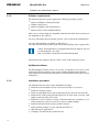
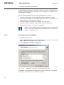
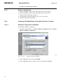
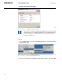
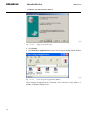
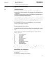
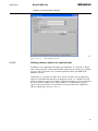
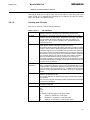
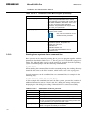
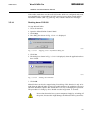
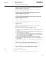
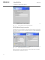
When installing MicroSCADA Pro or some other programs on server
versions of operating systems (2000/2003) use Add New Programs in
the Control Panel and browse the installation package. This will switch
Terminal Services automatically between install and run mode.
A070500
Fig. 2.1.4.-1
Add or Remove Programs window
MicroSCADA Pro installation procedure
To install the MicroSCADA Pro base product software:
15
SYS 600 9.2
MicroSCADA Pro
1MRS756115
Installation and Administration Manual
1. Restart the computer to remove possible memory resident data.
2. Logon as a user with administrator rights.
3. Double-click the installation icon to start the installation. It is recommended to
install using Add/Remove Programs from the Control Panel.
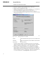
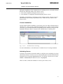
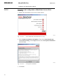
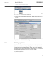
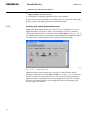
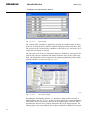
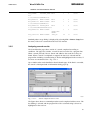
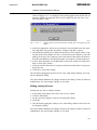
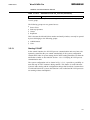
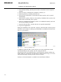
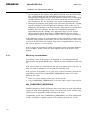
4. In the Product Installation dialog the software packages are listed, see
Fig. 2.1.4.-2. Select the software packages that you want to install by selecting
the appropriate check box.
A051494
Fig. 2.1.4.-2
Selecting products to be installed.
Program
contains MicroSCADA main program and must be installed in SYS
PC.
Workstation
monitor opening application (mons) is installed for VS and X Monitor
types
Documentation
will install documents
In practise, all three packages are installed in the SYS PC. This will allow
opening VS monitors locally on SYS PC and reading documents. Workstation
package is installed on workstation PC if VS/X -type monitors are used.
5. Select the drive in which the application is to be installed. The installation
program suggests a destination drive for the MicroSCADA Pro installation. If
MicroSCADA Pro has been installed before, the destination drive used in the
previous installation is shown as a default drive. Otherwise, the default drive is
C. To select another drive, click Change Drive and choose the drive.
16
1MRS756115
MicroSCADA Pro
SYS 600 9.2
Installation and Administration Manual
MicroSCADA Pro must be installed on a disk drive physically located
in the base system computer. It cannot be installed on a logical disk
drive, for example a network drive.
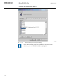
6. After selecting the components to be installed, click Start. If a previous
installation of the selected software package is detected, a System Information
dialog is shown.
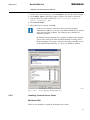
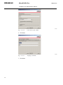
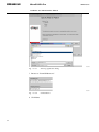
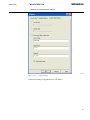
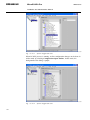
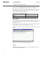
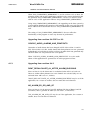
7. After the System Base Software has been installed, type a password for a
MicroSCADA user, see Fig. 2.1.4.-3. The MicroSCADA user is created during
the installation. It belongs to the Administrator group and it is the user who owns
the MicroSCADA processes.
The MicroSCADA user performs all references made by the processes. If two
base system computers share resources, the MicroSCADA user should be given
the same password on both computers. The password can be changed later from
the MicroSCADA Pro Control Panel.
This user name should not be used for purposes other than
administration tasks. If the MicroSCADA user already exists due to a
previous installation, the password is not changed.
A051498
Fig. 2.1.4.-3
MicroSCADA User Password dialog
8. After base software is installed, other selected packages are installed.
9. The installation completed dialog is shown when MicroSCADA Pro has been
installed.
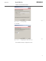
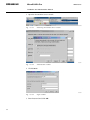
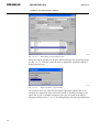
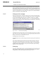
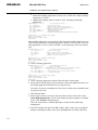
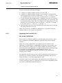
Installing COM 500i
Existing product COM 500 is included in SYS 600 9.2 or newer as a functionality
- COM 500i that is license dependent. COM 500i is a communication gateway
running on a MicroSCADA Pro platform. It provides a gateway between process
devices and eight Network Control Centers (NCC). The main tasks of COM 500i are
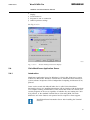
signal rerouting and protocol conversions. A COM 500i tab is constructed, when the
SYS 600 is started for the first time. Select the COM 500i tab from the Tool manager
to use the COM 500i functions, see Fig. 2.1.4.-4.
17
MicroSCADA Pro
SYS 600 9.2
1MRS756115
Installation and Administration Manual
A060262
Fig. 2.1.4.-4
COM 500i
COM 500i also handles the situation, when an existing COM 500
product is upgraded to SYS 600 9.2 or newer version.
Installing Microsoft Message Queuing (MSMQ)
Microsoft Message Queuing (MSMQ) is installed during SYS 600 installation and
the following installation steps are required if MSMQ is not already installed as part
of operating system installation.
Microsoft Windows installation disc may be required to complete the
installation.
To install Microsoft Message Queuing (MSMQ) on Windows 2000
1.
2.
3.
4.
5.
6.
In the Windows Components wizard, check Message Queuing.
Click Next.
Select Independent client.
Click Next.
Select Message queuing will not access a directory service.
Click Next to complete installation.
To install Microsoft Message Queuing (MSMQ) on Windows
Server 2003
1.
2.
3.
4.
5.
18
In the Windows Components wizard, select Application Server.
Click Details.
Check Message Queuing.
Click OK.
Click Next to complete the installation.
1MRS756115
MicroSCADA Pro
SYS 600 9.2
Installation and Administration Manual
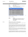
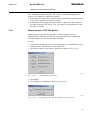
To install in Terminal Services environment
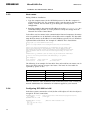
After program installation, edit MMC500_TS.cmd to match installation drive, then
run the command file. In a multi user environment like Terminal Server, Dynamic
Link Libraries (the .DLL files) may fail to open if more than one user attempts to
use them. The REGISTER utility allows you to tell the system that a particular .DLL
file should be made available globally to the system and to all users.
A070501
Fig. 2.1.4.-5
2.1.5.
Editing command
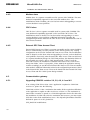
Verifying SYS 600 installation
During the installation of the MicroSCADA Pro kernel software, two empty
applications are created. The two applications are named TUTOR and WD.
The desktop icons for the MicroSCADA Pro Control System SYS 600 is created
during the installation. See Fig. 2.1.5.-1.
A070508
Fig. 2.1.5.-1
Desktop icon
SYS 600 Control Panel
The SYS 600 Control Panel dialog contains application management tools. The
MicroSCADA system can be started by clicking Start and stopped by clicking Stop
from these Application management tools.
19
SYS 600 9.2
MicroSCADA Pro
1MRS756115
Installation and Administration Manual
A051222
Fig. 2.1.5.-2
MicroSCADA Control Panel
SYS 600 Notify
The revision information and all the possible error messages that occur during the
start-up and operation of SYS 600 are shown in the Fig. 2.1.5.-3.
A070509
Fig. 2.1.5.-3
SYS 600 Notification Window
SYS 600 Monitor Pro
When an operator wants to supervise an application on a monitor screen of type VS
or X, the operator opens a MicroSCADA Pro monitor.
20
1MRS756115
MicroSCADA Pro
SYS 600 9.2
Installation and Administration Manual
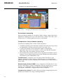
A070510
Fig. 2.1.5.-4
Monitor Pro Startup Window
SYS 600 Monitor
When an operator wants to supervise an application on a monitor screen of type VS
or X, the operator opens a SYS 600 Monitor with the MicroSCADA Monitor dialog.
A051226
Fig. 2.1.5.-5
MicroSCADA monitor dialog
External OPC DA Client
21
SYS 600 9.2
MicroSCADA Pro
1MRS756115
Installation and Administration Manual
A070511
Fig. 2.1.5.-6
External OPC DA Client
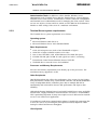
The shortcut menu for External OPC DA Client Control Panel provides a link to
External OPC DA tools.
Documentation
This icon links to Status Codes and Operation Manual.
61850 OPC Server
This icon links to Communication Engineering (CET) tool.
A070512
Fig. 2.1.5.-7
CET Tool
Applications
You can add additional applications by using the administration tools accessed from
the MicroSCADA Control Panel. The MicroSCADA administration tools also
provide means for listing and removing applications. When you add an application,
the application directories for the new application are created. The startup and
initialization pictures and dialogs are copied to the application directory apl_.
To open the Control MicroSCADA Applications dialog:
22
1MRS756115
MicroSCADA Pro
SYS 600 9.2
Installation and Administration Manual
1. Open the MicroSCADA Control Panel by double-clicking the icon.
A070513
Fig. 2.1.5.-8
Control MicroSCADA Applications dialog
2. Click Admin.
3. Click Applications to open the Control MicroSCADA Applications dialog.
In this dialog, it is possible to view, add, prepare and remove the applications.
Adding applications
To add a new application:
1. In the Control MicroSCADA Applications dialog, click Add to open the Add
new application dialog, see Fig. 2.1.5.-9.
A051504
Fig. 2.1.5.-9
Adding new application
23
MicroSCADA Pro
SYS 600 9.2
1MRS756115
Installation and Administration Manual
2. Type the name of the application to be created.
3. Click OK.
The new application directory and its subdirectories are created under the \sc\apl
directory. The initialization and startup pictures and dialogs are copied into the pict
subdirectory of the new application.
Preparing applications
When preparing an application, the necessary startup and initialization files are
copied to the application directory. If application is added as described before, it is
also prepared and no further preparations are needed. However, if MicroSCADA is
updated, applications need to be prepared again to use tools properly.
To prepare an application:
1.
2.
3.
4.
Open the Control MicroSCADA Applications dialog.
Select the application to be prepared.
Click Base Tools.
Select one of the following options:
*
Full prepare - copies all the initialization files and pictures to the application
directory. The possible existing files are overwritten.
*
Limited prepare - to copy initialization files but not the APL_INIT and
APL_START pictures. Use this option if you wish to keep the existing
APL_INIT and APL_START files. For instance, if you have prepared the
application for LIB 500, you should use Limited prepare.
If LIB 500 is used, prepare the applications for LIB 500.
1. Open the Control MicroSCADA Applications dialog.
2. Select the application to be prepared.
3. Click LIB 500 and refer to the LIB 500 documentation to complete the
preparation.
Removing applications
To remove an existing application:
1. Open the Control MicroSCADA Applications dialog.
2. Select the application to be removed.
3. Click Remove to remove the selected application directory and its subdirectories.
Using this utility physically removes the application from the SYS 600
computer file system. Therefore it is important to verify that the backup
of the application exists, in case it is required for later use.
24
1MRS756115
MicroSCADA Pro
SYS 600 9.2
Installation and Administration Manual
2.2.
Local Area Network (LAN)
A local area network (LAN) is a group of computers and associated devices that
share a common communications line or wireless link. Local area networks are built
with hardware such as Ethernet cables, network adapters, hubs and managed or
unmanaged switches. Wireless LAN and other more advanced LAN hardware
options also exist. LANs connect MicroSCADA workstations and SYS 600
computers and other supported devices like IEDs using IEC 61850 protocol. Each
individual device connected to LAN has its own IP address. They are able to access
data and devices anywhere on the LAN, they can share resources on LAN. Users
can also use the LAN to communicate with each other. There are many different
types of LANs. Our scope is on Ethernet and used protocol is TCP/IP. See detailed
installation instructions from corresponding Windows Operating System manual.
2.2.1.
Network interface card
Each computer on the LAN contains a network interface card and software for
handling the card and the used protocols.
Insert the network interface card before installing the Windows operating system.
Most computers are equipped with a built-in network interface card. The LAN
software is installed and configured during the operating system installation.
2.2.2.
IP addresses
The communication protocol supported by MicroSCADA is TCP/IP.
Each node or host in a TCP/IP network has an unique identifier, also called an IP
address. The IP address is composed of four numbers in the range from 0 to 255.
The numbers are separated with dots. For example: 192.168.0.1
The smallest LAN can have exactly two computers, a large LAN can accommodate
many thousands of computers. Because every computer on an IP network must have
a unique IP address, careful planning of IP addresses to the whole system is
important. You should remember to take care of the future needs in address areas
when planning large networks.
There are some special IP addresses. 127.0.0.1 is known as the loopback address
and it always refers to the local computer. Hostname used for the address is
'localhost'.
Use static addressing in MicroSCADA networks.
The IP addresses of the MicroSCADA Pro base system and workplaces must
comply with the addresses of other nodes on the network. Consult the local area
network administrator for valid IP addresses and other LAN configuration issues.
This document does not include planning guide for TCP/IP networks. You can find
these guides from Microsoft or other Internet sites.
25
MicroSCADA Pro
SYS 600 9.2
1MRS756115
Installation and Administration Manual
2.2.3.
Host names
During Windows installation:
1. Type the computer name for the NETBIOS protocol so that the computer is
recognized on the LAN. The computer's name is not the same as the host name
used by TCP/IP. The host name is given during the TCP/IP protocol
configuration.
2. Read the computer's host name and IP address by typing: ipconfig /all in a
Command Prompt window. It is also possible to verify the settings from the
Network Tool in the Control Panel.
To be able to use host names in the communication front-end computers, the names
to be recognized have to be defined in a host table on the computer. The host table
maps the host name to an IP address. On most Windows systems it is at C:\Windows
\System32\Drivers\Etc\Hosts. An example of a HOSTS file is listed below:
#
#
#
#
#
#
#
#
#
#
#
#
#
#
#
#
#
Copyright (c) 1993-1999 Microsoft Corp.
This is a sample HOSTS file used by Microsoft TCP/IP for Windows.
This file contains the mappings of IP addresses to host names. Each
entry should be kept on an individual line. The IP address should
be placed in the first column followed by the corresponding host name.
The IP address and the host name should be separated by at least one
space.
Additionally, comments (such as these) may be inserted on individual
lines or following the machine name denoted by a '#' symbol.
For example:
102.54.94.97
38.25.63.10
rhino.acme.com
x.acme.com
# source server
# x client host
The following is an example of a host table. Here each node has two names, one in
lower case letters and one in upper case letters. The items in a host table are
separated by spaces or tabs.
127.0.0.1
localhost
10.58.125.45
apassi
APASSI
10.58.125.46
ws1
WS1
10.58.125.47
ws2
WS2
10.58.125.48
fe1
FE1
There are, however, other mechanisms such as DNS that can be used. Consult your
network administrator for information on solutions applied to your network.
2.2.4.
Configuring SYS 600 for LAN
In the base systems connected to a LAN, define a LIN object of LAN. One object is
enough for all LAN connections.
#CREATE LIN:V = LIST(- ;Link to other SYS or LAN frontend (requires TCP/IP)
LT = "LAN")
;Link type
#CREATE LIN1:B = %LIN
#CREATE NOD:V = LIST(LI = 1,NN = "10.58.125.131",DI = 10,DT = 30,-
26
;Node for LAN frontend or SYS
1MRS756115
MicroSCADA Pro
SYS 600 9.2
Installation and Administration Manual
SA = 232)
#CREATE NOD32:B = %NOD
#CREATE NOD:V = LIST(LI = 1,NN = "System2",DI = 10,DT = 30,SA = 230)
#CREATE NOD30:B = %NOD
2.2.5.
;Node for LAN frontend or SYS
Verifying the LAN communication
Use the ping utility to test the connectivity on the LAN and determine if a host is
available and active. The syntax is: ping host where 'host' is the computer's IP
address or node name on the network. If the computer responds, a message is
produced with some diagnostic information.
A070514
Fig. 2.2.5.-1
Testing LAN Connectivity
Example:
Ping 192.10.0.210
Reply from 192.10.0.210: bytes = 32 time < 10ms TTL 255
The typical reply time is below 10ms. If the reply time exceeds 50 ms on normal 10/
100Mb/s Wired or Fibre Optic Network, it is recommended to check the LAN
communication equipment.
2.3.
Installing workplaces
2.3.1.
Installing Terminal Services
Terminal Services is a component of Microsoft Windows (both server and client
versions) that allows a user to access applications and data stored on a remote
computer over a network. This feature is needed to be able to open
MicroSCADA Pro FrameWindow –type pictures on workstations.
27
SYS 600 9.2
MicroSCADA Pro
1MRS756115
Installation and Administration Manual
A050195
Fig. 2.3.1.-1
Principles of Terminal Server based computing
Server-based computing
With server-based computing it is possible to deploy, manage, support and execute
applications completely on a server. The client devices, whether “fat or thin”, have
instant access to it without application rewrites or downloads.
Components of server-based computing
Server-based computing relies on three critical components:
1. A multiuser operating system that allows multiple concurrent users to log on and
run applications in separate, protected sessions on a single server.
2. A remote presentation services architecture capable of separating the
application's logic from its user interface, in such a way that only keystrokes,
mouse clicks, and screen updates travel the network.
3. The Terminal Server product consists of four components: the Windows Server
multiuser core, the Remote Display Protocol, the Windows-based client software
and enhanced system administration tools.
Terminal Server: A multiuser server core that provides the ability to host
multiple, simultaneous client sessions on Windows Server 4.0 (Terminal Server
Edition) and on later versions of Windows Server (Windows Server 2000, Windows
Server 2003).
Remote Display Protocol (RDP): A key component of Terminal Server is the
protocol, which allows a client to communicate with the Terminal Server over the
network. It is a multichannel protocol tuned for high-bandwidth enterprise
environments. Furthermore, it supports three levels of encryption.
Terminal Server Client: The client software presenting or displaying the 32-bit
Windows user interface on a range of desktop hardware.
28
1MRS756115
MicroSCADA Pro
SYS 600 9.2
Installation and Administration Manual
Administration Tools: In addition to all the familiar Windows Server
administration tools, Terminal Server adds the Terminal Server License Manager,
Terminal Server Client Creator, Terminal Server Client Connection Configuration
and Terminal Server Administration tools for managing the client sessions. There
are two new objects, Session and User, which are also added to the Performance
Monitor to allow tuning of the server in a multiuser environment.
2.3.2.
Terminal Server system requirements
The Terminal Server system requirements are as follows.
Operating system:
*
*
Microsoft Windows 2000 Server or
Microsoft Windows Server 2003 Standard Edition
Base Requirements:
*
*
*
*
*
*
32-bit x86 microprocessor (such as Intel PentiumIII or higher)
1024x768 or higher resolution monitor, 256 colors
One or more hard disks, with 1GB minimum of free hard disk space
256 MB of RAM, plus 10 MB for each typical user who is connecting
Transmission Control Protocol/Internet Protocol (TCP/IP)
CD-ROM drive or network access for installation
Processor and Memory Requirements:
Processor and memory requirements scale linearly up to four processors. The
maximum memory supported is 4 GB.
Other Peripherals:
Hard disk throughput also affects the performance of the system. For the highest
disk performance, consider using a SCSI RAID controller. The RAID (Redundant
Array of Independent Disks) controllers place data on multiple disk drives
automatically and can therefore increase disk performance and improve data
reliability.
Although the Remote Desktop Protocol used with Terminal Server causes negligible
network load, a high-performance network interface card (NIC) is recommended.
This is particularly important, if many users require access to data stored on network
servers or run client/server applications.
If a multiport asynchronous communications adapter is installed for supporting dialin users, be sure to use an intelligent (microprocessor-based) adapter to reduce
interrupt overhead and increase throughput.
Client System:
29
MicroSCADA Pro
SYS 600 9.2
1MRS756115
Installation and Administration Manual
A Terminal Server Client can be used on a client PC to access a Terminal Server
using the TCP/IP protocol from a network or by connecting via a Remote Access
Service (RAS) connection.
The minimum requirements for the 32-bit Terminal Server Client are:
*
*
*
*
*
Personal computer with an x86 compatible processor, Pentium or higher.
The Client is available on any Windows operating system. It is included or can
be downloaded to older Windows versions.
1024x768 or higher resolution video adapter, min. 256 colors.
Network interface card (NIC) using the Microsoft TCP/IP protocol.
Microsoft serial mouse or 100 percent compatible.
Windows XP or Windows 2000 Professional does not contain Terminal
Services, but only the RDP Client. Terminal Services is a feature of
Windows 2000/2003 Servers.
2.3.3.
Licensing service installation
To install the license service:
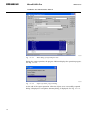
1. Choose Terminal Server Licensing during product setup, or at any time click the
Add or Remove Programs icon on Control Panel.
2. Click Add/Remove Windows Components.
A051187
Fig. 2.3.3.-1
Add/Remove Components, Terminal Services Licensing
In Windows Server 2003, the licensing service can be installed on a workgroup
based server, a member server or a domain controller.
30
1MRS756115
MicroSCADA Pro
SYS 600 9.2
Installation and Administration Manual
During the installation of the Terminal Server Licensing service, you need to choose
between the following modes of the license server:
*
*
Your entire enterprise (enterprise license server)
Your domain or workgroup (domain/workgroup license server)
Normally, your domain or workgroup is used. In this scenario, a license server is
automatically discovered by any terminal server within the same subnet as the
license server.
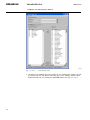
License installation
License tokens must be installed on your license server in order to deploy them to
client devices. After you have purchased Terminal Service Client Access Licenses
(TS CAL)s, you can then install the corresponding license tokens by using the CAL
Installation Wizard, which is located in the Terminal Server Licensing tool.
A070706.
Fig. 2.3.3.-2
Terminal Services Licensing
For more information, see the Microsoft Terminal Server Licensing document.
Activating license
A license server must be activated in order to certify the server and allow it to issue
client license tokens. A license server is activated using the Activation Wizard in the
Terminal Server Licensing administration tool. To activate a license server, select
Action > Activate Server while the server is highlighted.
There are three connection methods to activate your license server:
31
MicroSCADA Pro
SYS 600 9.2
1MRS756115
Installation and Administration Manual
*
*
*
Internet (Automatic): The quickest and easiest way to activate and install
licenses, which is also recommended by Microsoft. This method requires
Internet connectivity from the device running the Terminal Server Licensing
admin tool. Internet connectivity is not required from the license server itself.
The internet method uses TCP/IP (TCP port 443) to connect directly to the
Clearinghouse.
Web: The Web method should be used when the device running the Terminal
Server Licensing admin tool does not have internet connectivity, but you do have
access to the Web by means of a Web browser from another computer. The URL
for the Web method is displayed in the Activation Wizard.
Phone: The phone method allows you to talk to a Microsoft Customer Service
Representative to complete the activation or license installation transactions. The
appropriate telephone number is determined by the country/region you choose in
the Activation Wizard and is displayed by the wizard.
A license server must be activated only once. While waiting to complete the
activation or license token installation processes, your license server can issue
temporary tokens for clients that allow Terminal Server Licensing.
Purchasing license
The process for purchasing TS CALs for Windows Server 2003 remains the same as
for purchasing other Microsoft Client Access licenses. Customers might purchase
these licenses by obtaining a Microsoft License Pack (MLP), Microsoft Open
License, or through one of Microsoft's volume licensing programs, such as
Microsoft Select.
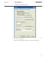
2.3.4.
Installing Windows 2000/2003 Terminal Services
To install Windows 2000/2003 Terminal Services:
1. Open the Control Panel.
2. Double-click the Add/Remove Programs icon. The Add/Remove Programs
dialog is displayed.
3. Click Add/Remove Windows Components on the left pane. The Windows
Components Wizard is displayed.
4. Scroll down the list to find Terminal Services and choose it by selecting a check
box on the left of it. If you click Details, you will see that there are two subcomponents:
*
Client Creator Files
*
Enable Terminal Services. See Fig. 2.3.4.-1.
32
1MRS756115
MicroSCADA Pro
SYS 600 9.2
Installation and Administration Manual
A050088
Fig. 2.3.4.-1
Subcomponents of Terminal Services dialog
5. The next dialog informs you to install Terminal Services to run in one of the two
modes:
*
Remote Administration or
*
Application Server.
The Application mode is required. This also requires the Terminal Services
Licensing service to be installed. A Terminal Services Client Access License
is also required for non-Windows 2000 Professional clients.
6. After selecting the mode, click Next to continue.
The following two dialogs concern the applications. In the first dialog, you can
determine how much you would like to restrict the users from accessing the
registry. Some applications store user settings in the registry, and will therefore
need more permission to it than others.
7. Select Windows 2000 Users. A warning dialog may appear even if everything is
done correctly. After that, the file copying progress dialog is displayed.
8. Click Finish to finish the installation.
9. Restart the computer.
Windows Server 2003
When you install Windows Server 2003, you are not prompted to install Terminal
Services. You can only enable or disable connections to the computer.
You can use Add or Remove Programs to install Terminal Server.
33
MicroSCADA Pro
SYS 600 9.2
1MRS756115
Installation and Administration Manual
A070708
Fig. 2.3.4.-2
Installing Terminal Services
Terminal Server Licensing is a required component that licenses clients on a
terminal server. You must install Terminal Server Licensing or your terminal server
will stop accepting connections from unlicensed clients 120 days from the date of
the first client logon. For small deployments, it is acceptable to install both the
Terminal Server and Terminal Server Licensing service on the same physical
computer. For larger deployments, it can be installed on a separate server.
Managing Terminal Services Users
Each user who logs on to a Terminal Services session must have a user account
either on the server or in a domain on the network that the server is on. The Terminal
Services user account contains additional information about the user.
Windows Server 2003 family operating systems contain a built-in User group called
Remote Desktop Users, which is used to manage Terminal Services users.
When you install one of the Windows Server 2003 operating systems, the Remote
Desktop Users group is one of the built-in user groups on your computer. Members
of this group have the same access as members of the Users group, but they have the
additional ability to log on remotely to the computer. By default, this group is not
populated when you install Terminal Server. You must choose the users and groups
that you want to have permission to log on remotely to the terminal server, and
manually add them to the Remote Desktop Users group.
To add users to the Remote Desktop Users group:
1.
2.
3.
4.
34
Open Computer Management.
In the console tree, click the Local Users and Groups node.
In the details pane, double-click the Groups folder.
Double-click Remote Desktop Users, and then click Add.
1MRS756115
MicroSCADA Pro
SYS 600 9.2
Installation and Administration Manual
5. On the Select Users dialog box, click Locations to specify the search location.
6. Click Object Types to specify the types of objects you want to search for.
7. Type the name you want to add in the Enter the object names to
select (examples): box.
8. Click Check Names.
9. When the name is located, click OK.
In the server computer, client users were previously granted
Administrator rights to get access to the MicroSCADA and its related
tools from the client computer. The following now describes an
alternative solution.
By default, a Remote Desktop Users group is available in the operating
system. The client login names should be defined to belong to this
Remote Desktop Users group. After this, the rights to Modify Access
to the MicroSCADA directory, i.e.<drive>\sc should be granted.
A070740
Fig. 2.3.4.-3
2.3.5.
Access rights for MicroSCADA users
Installing Terminal Server Client
Windows 2000
There are two methods to install the Terminal Server Client.
35
SYS 600 9.2
MicroSCADA Pro
1MRS756115
Installation and Administration Manual
The Client Creator can be used to create disks for installing the client software on a
user's computer. You can use these disks to distribute the appropriate Terminal
Services Client to each user.
One of the directories created in Terminal Services installation is WINNT\system32
\clients\tsclient.
By sharing this directory as read-only, you can install the Terminal Server Client
over the network without using discs. This is done simply by running setup.exe
from the net\win32 directory.
Windows Server 2003/XP Professional computers
The Client is installed as default.
The Terminal Services Client, called the Remote Desktop Connection (RDC),
provides substantial improvements over previous releases, including greater
functionality through a simplified user interface.
Remote Desktop Connection for Windows XP (Terminal Services Client 6.0) is
available from Microsoft site (see KB925876). This will give some new useful
features, for example, it is possible to use large two monitor displays on
workstations.
This version of Remote Desktop Connection (Terminal Services Client 6.0) can be
installed on client computers running Windows XP Service Pack 2. It can be used to
connect to terminal servers or remote desktops running earlier versions of Windows,
but the new features are available only when the remote computer is running
Windows Vista or Windows Server, code name "Longhorn."
2.3.6.
Remote Display Protocol (RDP) Client
To open the Remote Desktop Connection (RDP) Client select Startup >
Accessories > Communications > Remote Desktop Connection. See Fig. 2.3.6.-1
below.
A051130
Fig. 2.3.6.-1
Opening the Remote Desktop Connection
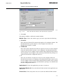
Customizing the Remote Connection
To change the various options for configuring the remote connection, a property
sheet with tabs shows the controls for
36
1MRS756115
MicroSCADA Pro
SYS 600 9.2
Installation and Administration Manual
*
*
*
*
Display
Local Resources
Programs to run on connection
Other Experience settings
See Fig. 2.3.6.-2
A070515
Fig. 2.3.6.-2
Remote Desktop Connection Display
2.4.
Citrix MetaFrame Application Server
2.4.1.
Introduction
MetaFrame Application Server for Windows is Citrix's thin client/server system
software for Microsoft's Windows Terminal Server. MetaFrame thin client/server
system software incorporates Citrix's Independent Computing Architecture (ICA)
protocol.
Latest version tested with MicroSCADA Pro is called Citrix MetaFrame
Presentation Server 4.0. Installing MetaFrame will not interfere with the functions
of a computer running Terminal Server. This means that clients can connect and
execute programs on the server regardless of whether they are running the Citrix
ICA protocol, or the standard Terminal Server client using RDP. The main
differences are in the features each protocol and its respective clients support.
Install MetaFrame Presentation Server after installing the Terminal
Services.
37
MicroSCADA Pro
SYS 600 9.2
1MRS756115
Installation and Administration Manual
2.4.2.
System requirements
*
*
*
*
*
Microsoft Windows 2000 Server and Service Pack 4.0 (or later) or
Microsoft Windows Server 2003 and Windows Server 2003 SP1
Microsoft NET Framework version 1.1
Java Runtime Enviroment (JRE) version 1.4.1_02 (or later)
ASP.NET (Microsoft component)
2.4.3.
Installing Citrix MetaFrame Presentation Server 4.0 system
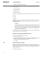
2.4.3.1.
Windows components installation
To install the Windows component:
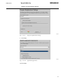
1. From the Control Panel, go to Add or Remove Programs and select Add or
Remove Windows Components.
A070516
Fig. 2.4.3.1.-1
Windows Component Wizard
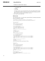
2. Select Application Server and click Details.
3. Select Application Server Console, if not yet checked and ASP.NET.
38
1MRS756115
MicroSCADA Pro
SYS 600 9.2
Installation and Administration Manual
A070517
Fig. 2.4.3.1.-2
Application Server dialog
4. Click OK in the Application Server dialog and click Next in the Windows
Components Wizard.
5. Click Finish.
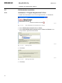
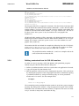
2.4.3.2.
Get Citrix license file from internet
1. Go to http://mycitrix.com. The Citrix Login page is displayed.
A070518
Fig. 2.4.3.2.-1
2.
3.
4.
5.
Citrix Login Window
Type Login ID, Password and click Login.
Click Licensing.
Click Citrix Activation System (CAS).
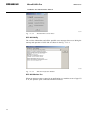
Click Activation of licenses. Follow the rules for Citrix License Activation.
39
SYS 600 9.2
MicroSCADA Pro
1MRS756115
Installation and Administration Manual
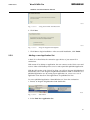
2.4.3.3.
Installation and configuration of MetaFrame Access Suite
licensing
1. Install Citrix Presentation server CD in a SYS 600 PC.
A070519
Fig. 2.4.3.3.-1
Citrix MetaFrame Presentation Server setup
2. Select Product installations and updates. Then select Install MetaFrame
Access Suite licensing, click Accept and next select Prerequisites Installation
and click Next.
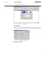
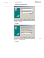
A070520
Fig. 2.4.3.3.-2
3. Click Next.
40
Prerequisites installation
1MRS756115
MicroSCADA Pro
SYS 600 9.2
Installation and Administration Manual
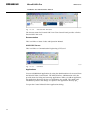
A070521
Fig. 2.4.3.3.-3
Component selection
4. Click Next.
41
SYS 600 9.2
MicroSCADA Pro
1MRS756115
Installation and Administration Manual
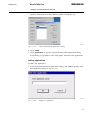
A070522
Fig. 2.4.3.3.-4
Citrix MetaFrame Access Suite licensing setup
5. Click Next and then accept Destination Folder by clicking Next. Accept the
selected features and click Next.
42
1MRS756115
MicroSCADA Pro
SYS 600 9.2
Installation and Administration Manual
A070523
Fig. 2.4.3.3.-5
License files location
6. In the License Files Location, copy your license file in SYS 600 to c:\Program
Files\Citrix\Licensing\MyFiles\
A070524
Fig. 2.4.3.3.-6
Web Server selection
7. Select Next.
A070525
Fig. 2.4.3.3.-7
Restart server dialog
8. Click Next and then Finish.
43
SYS 600 9.2
MicroSCADA Pro
1MRS756115
Installation and Administration Manual
2.4.3.4.
Install MetaFrame Presentation Server 4.0 and its components
1. Click Install MetaFrame Presentation Server 4.0 and its components as
shown in the figure below.
A070526
Fig. 2.4.3.4.-1
MetaFrame Presentation Server and components installation dialog
2. Accept the license agreement and continue.
A070527
Fig. 2.4.3.4.-2
License agreement
A070528
Fig. 2.4.3.4.-3
3. Click Next.
44
Component Selection for MetaFrame Presentation Server
1MRS756115
MicroSCADA Pro
SYS 600 9.2
Installation and Administration Manual
A070529
Fig. 2.4.3.4.-4
Warning dialog
4. Follow the Components Setup messages. In most cases there is no need change
default setup.
5. The following is an example setting when joining a Farm.
A070530
Fig. 2.4.3.4.-5
Server farm window
Farm name: SCADA
45
SYS 600 9.2
MicroSCADA Pro
1MRS756115
Installation and Administration Manual
A070531
Fig. 2.4.3.4.-6
Create Server farm window
6. Click Next.
A070532
Fig. 2.4.3.4.-7
7. Click Next.
46
Assigning credentials
1MRS756115
MicroSCADA Pro
SYS 600 9.2
Installation and Administration Manual
A070533
Fig. 2.4.3.4.-8
Licensing settings
8. Click Next.
A070534
Fig. 2.4.3.4.-9
Configuring Citrix XML Service Port
The installation summary is displayed at the end.
47
SYS 600 9.2
MicroSCADA Pro
1MRS756115
Installation and Administration Manual
A070535
Fig. 2.4.3.4.-10
Installation summary window
Citrix will set Only Launch Published Applications selection on both
connection types, ICA and RDP. Installing Citrix MetaFrame affects
also Terminal Services RDP! You have to deselect Only Launch
Published Applications.
To do so:
1. Go to All Programs -> Citrix -> Administration Tools -> Citrix Connection
Configuration Tool
A070536
Fig. 2.4.3.4.-11
Citrix Client configuration tool
2. In the Citrix Connection Configuration, right click “..rdp-tcp..” and click Edit.
48
1MRS756115
MicroSCADA Pro
SYS 600 9.2
Installation and Administration Manual
A070537
Fig. 2.4.3.4.-12
Citrix Connection Configuration
3. Deselect Only Launch Published Applications. Do the same procedure for icatcp also.
A070538
Fig. 2.4.3.4.-13
2.4.4.
Advanced connection settings
Publishing applications
It is MetaFrame Presentation Server's integral function to make applications and
their content available to users. If you are logged into a certain server farm, use
Presentation Server Console to publish applications on any server in the server farm.
You do not have to run Presentation Server Console from the same MetaFrame
Presentation Server, where the applications are installed. The server or servers, that
host the published applications, has to be a server farm member.
To publish an application:
49
SYS 600 9.2
MicroSCADA Pro
1MRS756115
Installation and Administration Manual
1. Open the Presentation Server console.
A070720
Fig. 2.4.4.-1
Launching Presentation Server console
A070721
Fig. 2.4.4.-2
Authentication window
2. Click Cancel.
A070722
Fig. 2.4.4.-3
Logon window
3. Enter Password and click OK.
50
1MRS756115
MicroSCADA Pro
SYS 600 9.2
Installation and Administration Manual
A070723
Fig. 2.4.4.-4
Selecting applications
4. Select Applications.
A070724
Fig. 2.4.4.-5
Selecting published applications
5. Select Actions > New > Publish Application.
A070725
Fig. 2.4.4.-6
Publishing wizard
6. Define the display name and application description and click Next.
51
SYS 600 9.2
MicroSCADA Pro
1MRS756115
Installation and Administration Manual
A070726
Fig. 2.4.4.-7
Selecting application dialog
7. Browse to “FrameWindow.exe”
A070727
Fig. 2.4.4.-8
8. Click Next.
52
Command line
1MRS756115
MicroSCADA Pro
SYS 600 9.2
Installation and Administration Manual
A070728
Fig. 2.4.4.-9
Program neighborhood settings
9. Click Next.
A070729
Fig. 2.4.4.-10
Application appearance
10.Click Next.
53
SYS 600 9.2
MicroSCADA Pro
1MRS756115
Installation and Administration Manual
A070730
Fig. 2.4.4.-11
Client requirements
11.Click Next.
A070731
Fig. 2.4.4.-12
12.Click Next.
54
Configuring access control
1MRS756115
MicroSCADA Pro
SYS 600 9.2
Installation and Administration Manual
A070732
Fig. 2.4.4.-13
Specifying servers
13.Add server and click Next.
A070733
Fig. 2.4.4.-14
Specifying users
14.Click Finish and exit from the Management Console.
55
SYS 600 9.2
MicroSCADA Pro
1MRS756115
Installation and Administration Manual
2.5.
2.5.1.
ICA Workstation Installation
Installation of “Program Neighborhood”-Client
1. Install Citrix Presentation server CD (Components Disk ) to Workstation.
A070715
Fig. 2.5.1.-1
Citrix MetaFrame Presentation Server Clients
2. Select MetaFrame Presentation Server Clients.
3. Select Install MetaFrame Presentation Server Client for Windows, next
accept License Agreement and continue.
A070716
Fig. 2.5.1.-2
Selecting client
4. Click Next.
A070717
Fig. 2.5.1.-3
5. Click Next.
56
Entering client name
1MRS756115
MicroSCADA Pro
SYS 600 9.2
Installation and Administration Manual
A070718
Fig. 2.5.1.-4
Using Local Name and Password
6. Click Next.
A070719
Fig. 2.5.1.-5
Program Neighborhood Options
7. Click Next to begin installation. After successful installation, click Finish.
2.5.2.
Adding a new Application Set
A basic ICA client limits the connection type choices to just custom ICA
connections.
With custom ICA desktop or application, the user connects to the Citrix server and
receives either a full desktop on the server or runs a particular published application.
With the full version of the Citrix ICA client, you will get Program Neighborhood
functionality. The Citrix Program Neighborhood enables to make a connection to a
published application set. By setting up an application set, a user sees a set of
application icons based on what applications are published for him.
To access published application “FrameWindow.exe” from the workstation:
1. Browse to Program Neighbourhood and doubleclick.
A070539
Fig. 2.5.2.-1
Start Menu
2. Select Find New Application Set.
57
SYS 600 9.2
MicroSCADA Pro
1MRS756115
Installation and Administration Manual
A070540
Fig. 2.5.2.-2
Find new application set
3. Click Next.
4. Type the name SCADA1, click Server Location, add address and click OK.
A070541
Fig. 2.5.2.-3
New application set
5. Select the name of server from the drop-down list. Note that MicroSCADA Pro
is running on SV_SER1.
58
1MRS756115
MicroSCADA Pro
SYS 600 9.2
Installation and Administration Manual
A070542
Fig. 2.5.2.-4
Locating
6. Click Next.
A070543
Fig. 2.5.2.-5
Customizing settings
7. Click Next.
59
SYS 600 9.2
MicroSCADA Pro
1MRS756115
Installation and Administration Manual
A070544
Fig. 2.5.2.-6
Setup successful message
8. Click Finish.
9. Click Find New Application Set in the Citrix Program Neighborhood window.
A070545
Fig. 2.5.2.-7
Citrix Program Neighborhood Window
Logon settings of Application Set “SCADA1” User “valvomo” of SV_SER1 is a
member of Remote desktop users.
60
1MRS756115
MicroSCADA Pro
SYS 600 9.2
Installation and Administration Manual
A070552
Fig. 2.5.2.-8
Logon settings
Connection Settings of Application Set "SCADA1"
61
SYS 600 9.2
MicroSCADA Pro
1MRS756115
Installation and Administration Manual
A070549
Fig. 2.5.2.-9
Connection settings
Default Options of Application Set “SCADA1”
62
1MRS756115
MicroSCADA Pro
SYS 600 9.2
Installation and Administration Manual
A070550
Fig. 2.5.2.-10
Default options
When selecting Application Set “SCADA1” then following folder appears.
63
SYS 600 9.2
MicroSCADA Pro
1MRS756115
Installation and Administration Manual
A070551
Fig. 2.5.2.-11
FrameWindow MicroSCADA
To open a FrameWindow MicroSCADA picture select “SER1 SYS600 Pro
Monitor”
2.6.
Installing process communication units
2.6.1.
PC-NET process communication unit
The PC-NET process communication unit is a Windows executable which is
automatically installed when the SYS 600 packet is installed or upgraded. The
instances of these units are defined with the system configuration tool, see System
Configuration manual, chapter ‘Configuring process communication’. In runtime,
each configured NET in the system configuration will have a corresponding
pc_nets.exe process running.
Depending on configuration, the communication lines configured to PC-NET
instances will use serial ports, network adapters or PCLTA extension cards (LON
communication). The required hardware must be installed and configured before a
complete verification of the system configuration can be done.
The installation of the computer hardware used by PC-NET process communication
units is described in Section 2.6.1.1. Installing multiport serial card, Section 2.6.1.2.
Installing LON cards, Section 2.6.1.3. Installing network cards and Section 2.6.1.4.
Verifying PC-NET process communication unit.
2.6.1.1.
Installing multiport serial card
Each PC-NET instance supports 12 communication lines and in most cases,
additional COM ports are required. The usage of standard COM ports 1-4 is also
possible.
64
1MRS756115
MicroSCADA Pro
SYS 600 9.2
Installation and Administration Manual
The multiport serial card is an extension card which is installed to a PCI slot in the
motherboard of the PC. As to the installation procedure, refer to the installation
manual of the product. In principle, any PCI based serial card can be used but
following product lines and manufacturers are verified and widely used in
MicroSCADA Pro systems:
*
*
*
RocketPort from Comtrol Corp.
DigiBoard from Digi International
MOXA serial boards from Moxa Technologies, Inc.
The serial port products which are not PCI-based are also widely available.
However, as long as the COM ports provided by these products may disappear from
the system during runtime, the overall reliability of the system is worse than in PCIbased alternatives.
In all cases, for the COM port, the communication line used is defined with the SDattribute of the line object.
2.6.1.2.
Installing LON cards
For installation of LON cards, refer to Connecting LONWORKS Devices manual.
2.6.1.3.
Installing network cards
If the system configuration contains protocols which use LAN, the necessary
network adapters must be installed. In most cases, the process communication uses
the same network adapter as the MicroSCADA Pro base system and the installation
procedure is the same as described in Section 2.2. Local Area Network (LAN)
The communication lines created to PC-NET instances may use multiple local IPaddresses especially when there is multiple connection to Network Control Centers
(slave protocols) or the IEDs which are connected the MicroSCADA Pro are
divided to multiple networks (master protocols).
In Windows, it is possible to define multiple IP-addresses to the same network
adapter but it is also possible that the used IP-addresses are divided to multiple
network adapters. Multiple network adapters are often used in systems requiring
redundant communication lines. When the installation and the configuration of the
network adapters is complete, the successful ‘ping’ test described in Section 2.2.
Local Area Network (LAN) indicates that the given IP-address is present in the
system and it can be used by the PC-NET.
In all LAN protocols supported by PC-NET, line attribute LD defines which local
IP-address is used by the communication line.
65
SYS 600 9.2
MicroSCADA Pro
1MRS756115
Installation and Administration Manual
2.6.1.4.
Verifying PC-NET process communication unit
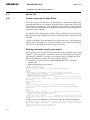
In order to verify the operation of the PC-NET process communication unit, the
system configuration must contain at least one configured NET node. When
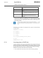
MicroSCADA Pro system is started, following printout shown in Fig. 2.6.1.4.-1 is
displayed in the notification window for each configured NET node.
A070502
Fig. 2.6.1.4.-1
Notification window
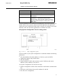
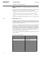
In case the configuration already contains communication lines and there are errors
in the configuration, corresponding printouts will be found from the notification
window as shown in Fig. 2.6.1.4.-2 and from file “sys_error.log”. In the printout
below, the communication line 1 in NET 2 has failed to open the serial port
configured for it. When this happens, usually the configured port is already in use or
the installation of the serial card is not complete and the given port cannot be found
from the system.
A070507
Fig. 2.6.1.4.-2
Notification window showing errors in configuration
As described in the system configuration manual, the startup of the PC-NET process
communication unit can be done also using the SCIL procedures. When this method
has been used and system is started, the existence of the NET nodes can be verified
e.g. using the ‘Open Online’ function of the system configuration tool. If the
66
1MRS756115
MicroSCADA Pro
SYS 600 9.2
Installation and Administration Manual
configuration contains errors, the error printout can still be found from the
notification window and the used status codes are the same as with the system
configuration tool. The status codes are listed in a separate MicroSCADA Pro
manual ‘Status Codes’.
2.6.2.
IEC 61850
The IEC 61850 related process communication unit is an Windows executable,
which has been automatically installed during the SYS 600 software installation.
Before any actual IEC 61850 process communication occurs from the set of IEC
61850 IED's (i.e. process devices) into SYS 600 process database, there is a need to
configure each of the IEC 61850 process communication units to represent the
certain part of the underlying process devices. This is made by using the tools
included into SYS 600 software, see IEC 61850 System Design manual, chapter
Configuration. At run-time, each configured IEC 61850 process communication
unit is called an instance. Each of these instances can be seen that the corresponding
opcs_iec61850.exe process is running.
The actual IEC 61850 protocol communication occurs over the physical TCP/IP
network. However depending on the selected configuration, different TCP/IP
network related hardware and software has been installed and configured
accordingly before the complete verification of the IEC 61850 system configuration
can be done, see IEC 61850 System Design manual, chapter Requirements.
2.7.
Installing peripheral equipment
2.7.1.
Installing printers
Printers are used for automatic event and alarm print, and for operator initiated hard
copy. For hard copy, the hard copy functions of eXceed or Windows can be used
without any configuration measures in MicroSCADA Pro. On the other hand, the
automatic event and alarm print requires that the printers are connected to
MicroSCADA Pro. These printers can also be used for MicroSCADA Pro initiated
hard copy. The installation descriptions below apply to the printers used by
MicroSCADA Pro. Regarding the installation of Windows hard copy devices, refer
to the Windows and the printer manuals.
A MicroSCADA Pro printer can be connected in the following ways:
*
*
*
2.7.1.1.
Directly to a base system computer, through the parallel port or a serial port.
To a LAN via a printer server.
Communication unit (NET, serial type connection)
Connecting printers to the base system
Printers connected to a NET unit can be made accessible to all base systems in the
entirely distributed MicroSCADA Pro system. A printer connected directly to a base
system can also be used by other base systems on the LAN. The printer has to be
67
MicroSCADA Pro
SYS 600 9.2
1MRS756115
Installation and Administration Manual
defined as “shared” in the computer's operating system configuration to which it is
directly connected. Printers connected to a LAN can be made accessible to all base
systems on the LAN.
On the application level, the printing can be accomplished according to two
different principles which determine the appearance of a printout:
*
*
Picture based printing (old, “out of use, no printers available” )
SCIL defined printing ("transparent" printing)
The SCIL defined printout can contain any characters supported by the printer.
The last mentioned type is specified by the SCIL function PRINT_TRANSPARENT.
The picture based printout produced by printers connected to a Windows computer
or a LAN is always semi-graphic. Pixel based printout can be obtained only on
printers connected to a NET. The fully graphic printout can be obtained on any
printers. Each base system and each application is able to recognize and use up to 20
printers. It is possible to configure virtual printers without a real physical
correspondence for logging in a file on a disk. When a printer is defined for printer
logging, all printout sent to the printer is stored on a disk. This is useful when
configuring an event log, that is a disk copy of the event list. A physical printer can
also be given more than one printer object definitions to enable several different
types of printout to the same printer. The printer operation can be supervised and
controlled, for example temporarily stopped and restarted, or the printout can be
redirected to another printer. This can be done by means of the ST and CL attributes
(refer to the System Objects manual).
2.7.1.2.
Connecting printers to LAN
Printers connected to a base system computer or LAN must be configured in all base
systems that uses the printers. Configure the printer in each base system as follows:
1. Create a PRIn:B base system object, with at least the following attributes (see
System Objects manual):
DT
"NORMAL" (black-and-white ASCII based print out) or
"TRANSPARENT" (SCIL defined print out)
DC
"LINE"
SD
Printer device name including UNC path (SD="\
\My_Computer\My_printer"). The printer must be shared
for the UNC name to be a valid value of the attribute
TT
"LOCAL"
In addition, optional features are defined by the following attributes:
68
1MRS756115
MicroSCADA Pro
SYS 600 9.2
Installation and Administration Manual
LP
Lines per page, this should > = the number set on the
printer
QM
Printer queue length
OD
Output destination: "PRINTER", "LOG" (disk files) or
"BOTH"
LD, LL, LF
Printer log attributes, specially the management of log
files. The attributes are meaningful, if OD = "LOG" or
"BOTH"
OJ
Open on Job Basis, set value to 1. The printer is opened
before each print job and closed when the job is
completed
2. If needed, map the printer for an application with the APLn:BPR attribute.
Printers can be mapped for an application, which means that the application
recognizes the devices under logical numbers. The printer mapping is required
only if you want to use a logical printer number which is not the same as the
printer object number.
Only the printers mapped with the logical printer numbers 1 ...15 can
be used as alarm and event printers; printer 15 is reserved for event
lists.
The following is an example of a configuration where a printer is connected directly
to a base system:
#CREATE PRI:V = LIST(TT = "LOCAL",DT = "NORMAL",DC = "LINE",SD = "\\My_SYS_name\My_Printer_name",LP = 66)
#CREATE PRI2:B = %PRI
2.7.1.3.
Connecting printers to PC-NET units
A printer connected to a NET can be used by all base systems connected to the same
network. The printer must be defined both in the base systems which uses it and in
the NET unit to which it is directly connected. It is assumed here that the NET unit
has been defined to the base system as a NODn:B object. Include the following
definitions in each base system which will use the printer:
1. Create a PRIn:B base system object with at least the following attributes:
69
SYS 600 9.2
MicroSCADA Pro
1MRS756115
Installation and Administration Manual
TT
"LOCAL"
ND
The node number of the NET unit to which the printer is
directly connected
TN
The device number of the printer in the NET unit to which it
is directly connected
DT
"COLOR", "NORMAL", or "TRANSPARENT". Select
"NORMAL", if the printer will be used exclusively for the
black-and-white character-based printout. Select
"COLOR" for all other types of picture-based printout. Even
the printer will be black-and-white, "COLOR" is preferable
as this mode provides a more picture resembling printout
by exchanging graphical characters to printer specific
characters. Select "TRANSPARENT", if the printout will be
SCIL defined.
DC
"NET"
In addition, optional features are defined by the following attributes:
LP
Lines per page
QM
Queue length maximum
OD
Output destination: "PRINTER", "LOG" (disk files) or
"BOTH"
LD, LL, LF
Printer log attributes, specially the management of log
files. The attributes are meaningful, if OD = "LOG" or
"BOTH"
2. If needed, map the printer for an application with the APLn:BPR attribute,
("Device Mapping"). The printer mapping is required only if you want to use a
logical printer number which is not the same as the printer object number.
Include the following definitions in the NET unit to which the printer is directly
connected:
1. Select a line for the printer and define the line with the ASCII protocol:
PO
4
IU
1
LT
0
MS, MI
System message handling, see chapter 17
PS
Buffer pull size, see
BR
Baud rate (recommended value 2400)
PY
0
RD
8
SB
1
TD
8
OS
Output synchronization, refer to the system objects
manual, chapter 13
2. Define a printer (a PRI object) on the selected printer line with the attributes:
70
1MRS756115
MicroSCADA Pro
SYS 600 9.2
Installation and Administration Manual
LI
The number of the selected line
IU
1
MI, MS
System message handling, see
AL, AS
0 (the printer reservation is handled automatically by the
base system)
PT
Printer type 1 = character-based, black-and-white 2 =
"transparent" 3 = pixel-based, black-and-white 4 =
character-based, black-and-white, graphical characters
replaced by printer characters 6 = Facit 4544 7 = pixelbased, color
For more information on the attributes of the PRI object, refer to the System Objects
manual. When a base system is started, its default application (the application
created first in SYS_BASCON.COM) sends a message to the printers (form feed).
Therefore, make sure that these applications are defined in the NETs.
Using System Configuration Tool for setting printer
A070737
Fig. 2.7.1.3.-1
Base configuration system
Create an outline of your system configuration or a table that includes the following
information:
*
*
*
*
The node numbers and station addresses of the base system and NETs.
Application numbers and possible names.
NET line numbers.
Station numbers (in NET and in the base system if different) and station
addresses (slave numbers) of all devices.
Use System Configuration Tool and do next steps:
1. Define a configuration, which at least contains the ASCII Printer communication
line.
2. Specify the ASCII Printer line specific attributes IU and SD.
3. Save the active configuration.
71
MicroSCADA Pro
SYS 600 9.2
1MRS756115
Installation and Administration Manual
4.
5.
6.
7.
Close the tool, re-open it, and open the active configuration.
Under Program/User_Defined you will find preconfigured file for printer.
Edit it (remove semicolons) to fit your purpose.
Stop the running MicroSCADA and re-start MicroSCADA.
A070738
Fig. 2.7.1.3.-2
System configuration tool
A070739
Fig. 2.7.1.3.-3
2.7.2.
SCIL editor
Installing adapter cards
To install an adapter card, mount the alarm card used into a free PCI expansion slot
in the base system computer. A PCI card selects the necessary I/O port addresses
automatically.
To use these cards, settings to SYS_BASCON.COM must be done:
72
1MRS756115
MicroSCADA Pro
SYS 600 9.2
Installation and Administration Manual
Alarm I/O cards
Set parameters SYS:BAA to value representing the card type you use
AA = 1;(if no AD is given then old Flytec card)
AW = xx;(seconds between watchdog pulses)
AD = "Nudaq PCI-7256"; supported Nudaq PCI-7256, Nudaq PCI-7250 or Advantech PCI1760
Watchdog output D25 pins 17 and 18 are open when program not running and
closed when running.
To check I/O, use test picture and next commands:
@A = audio_alarm( "all","on")
@A = audio_alarm("all","off")
@A = audio_alarm(xx,"on/off") xx=1..7
External clocks
To use a Meinberg PCI511 radio clock in the base system, set the SYS:BCL
attribute to one of next:
"NONE" = No external clock
"PC31 " = Radio clock used in PC/ATs. The radio clock is synchronised in accordance
with Central European radio time signals.
"PC32" = PC clock card of type PC32
"PCI510" = PC clock card type PCI510 and new PCI511
# CREATE SYS:V
.......
# SET SYS:BCL = "PC510"
# SET SYS:BCA = 1
.......
# CREATE SYS:B = % SYS
2.8.
Installing SYS 600 Application OPC Server
Hardware requirements
The SYS 600 Application OPC Server (AOPCS for short) has no specific hardware
requirements. It is compatible with any modern PC hardware. The client application
connecting to AOPCS may, of course, have its own hardware requirements.
Software requirements
AOPCS has been tested on the following operating systems:
*
*
*
*
*
Windows
Windows
Windows
Windows
Windows
2000 Professional
2000 Server
Server 2003
Server 2003, Enterprise x64 Edition
XP Professional
Installation
AOPCS may be installed in any directory. The installation dialog suggests the
directory \SC\PROG\AOPCS.
Configuration
73
SYS 600 9.2
MicroSCADA Pro
1MRS756115
Installation and Administration Manual
The instructions to configure the installed AOPCS can be found in the SYS 600
OPC Server manual.
74
1MRS756115
MicroSCADA Pro
SYS 600 9.2
Installation and Administration Manual
3.
System administration
3.1.
Transferring objects
The following common functionality is provided by the Export/Import tool:
*
*
*
Recognizing of all the application objects from the selected MicroSCADA Pro
application.
Defining the common options for the exported and imported application objects.
Exporting and importing application objects.
The common options for the exported and imported data are provided in the Export
and Import field. The application objects to be handled are listed in the Applications
Objects list. The progress of operation is indicated by using the progress indicator
and the status bar field. The user can operate by clicking the appropriate buttons in
the tool. See Fig. 3.1.2.-1
The Export/Import tool can also act as stand-alone tool and be consequently
accessed directly through Tool Manager.
Recognizing application objects
During the start-up of the tool, the list of MicroSCADA Pro applications is read.
The application, where the Export/Import tool has been started, is used as a default
item.
The list of object types contains the following application objects, which are
indicated with letters:
P
Process Object Groups
IX
Process Objects
X
Scale Objects
D
Data Objects
C
Command Procedures
T
Time Channels
A
Event Channels
UP
User Defined Process Objects
F
Free Type Objects
H
Event Handling Objects
It is also possible to select All Object Types from the Object Type drop-down list.
When All Object Types is selected, the Export/Import tool operates with all the
application objects found from the selected application.
Export/Import Tool composition
The Export/Import Tool is composed of:
*
*
a menu bar
a tabbed page containing search conditions
75
MicroSCADA Pro
SYS 600 9.2
1MRS756115
Installation and Administration Manual
*
*
Import, Export and Close buttons
a tabbed page containing application objects to be handled
At the lowest part of Export/Import Tool dialog, there is a status bar showing the
number of processed application objects found and selected.
3.1.1.
Opening and exiting Export/Import tool
Application Object Import/Export Tool can be run as a standalone tool or as a
Application Object Navigator's subtool. The standalone tool can be started by
clicking the Import/Export icon and then selecting File>Open, see Fig. 3.1.1.-1. If
the standalone tool is used, it is possible to export and import the application objects
according to the common options for the exported and imported data.
A050154
Fig. 3.1.1.-1
Export/Import icon
Application Object Export/Import Tool can also be started from the Object
Navigator menu item by selecting Data > Export.... See Fig. 3.1.1.-2. In this case,
the tool is started on export mode, that is it can only be used for exporting the
application objects. Depending on the selected application objects in the Object
Navigator, the common options in the Application Object Export/Import Tool
become assigned as defaults.
76
1MRS756115
MicroSCADA Pro
SYS 600 9.2
Installation and Administration Manual
A051193
Fig. 3.1.1.-2
Open the tool from the Object Navigator dialog
When Application Object Export/Import Tool is started from the Object Navigator
menu item by selecting Data > Import. See 3.1.1.-2. In this case, the tool is started
on import mode, i.e. it can only be used for importing the application objects. When
the import operation is finished, the selected Object Navigator view becomes
updated.
Close the Export & Import Tool by clicking the Close button. The tool can also be
closed by selecting Object > Exit or by the keystroke Alt+F4. See Fig. 3.1.2.-1.
3.1.2.
Exporting objects
Use common options to define the set of application objects to be exported. The
application objects that match the common options are listed in the Application
Objects tabbed page. Select the application objects that need to be exported. When
Select All is clicked, all the objects are selected. When Unselect All is clicked, none
of the objects are selected. To select separate application objects from the list, hold
the Ctrl key down while clicking the objects.
When the selection contains at least one application object, Export is enabled.
When the button is clicked, a destination (export) file is created. See Fig. 3.1.2.-1.
When Export All is clicked, all objects are exported without selecting any objects.
The Application Objects tabbed page shows only the first 10 000 objects in the list.
The button also exports the objects that are not shown in the tabbed page.
77
SYS 600 9.2
MicroSCADA Pro
1MRS756115
Installation and Administration Manual
A050155
Fig. 3.1.2.-1
Main dialog of Export/Import Tool
During the export operation, the progress indicator displays the operation progress.
See Fig. 3.1.2.-2.
A050158
Fig. 3.1.2.-2
Export operation progress dialog
At the end of the export operation, either the objects were successfully exported
dialog is displayed or exceptions summary dialog is displayed. See Fig. 3.1.2.-3.
78
1MRS756115
MicroSCADA Pro
SYS 600 9.2
Installation and Administration Manual
A050157
Fig. 3.1.2.-3
3.1.2.1.
Objects are successfully exported
Exporting formats
The Export/Import tool supports three formats:
*
*
*
ASCII File Format (ASC)
SCIL Database Format (SDB)
Comma Separated Values Format (CSV)
ASCII File Format (ASC)
The ASC Export format is an outdated export format. The ASC format is not
editable and data is saved in a slow sequential text file. The file name extension is .
asc by default.
SCIL Database Format (SDB)
The SDB export format is based on the SCIL database files or SCIL data files. The
SDB format is not editable. The SCIL database files are not limited and the SCIL
database's structure is optimized for fast access. Hence it is possible to transfer a
program in one step with the SDB export format. The file name extension is .sdb by
default.
Comma Separated Values Format (CSV)
The CSV export format is an editable export format and list-based engineering
(LBE) uses it. The file name extension is .csv by default.
3.1.2.2.
Defining CSV attributes
To form the CSV data, the following options are available:
*
Delimiter is Comma
The data's delimiter is a comma (,) instead of a semicolon (;). Select the
Delimiter is Comma check box, if the dot is used as a decimal point instead of
comma.
*
OI Attribute Split
79
MicroSCADA Pro
SYS 600 9.2
1MRS756115
Installation and Administration Manual
The OI (Object Identifier) attribute of process objects can have a structure. If the
structure exists and the OI Attribute Split check box is selected, the attribute's
value is splitted according to the attribute's structure.
*
Attribute Name Header
By default the first row of the CSV data represents the two letter attribute names,
which you can select. If the Attribute Name Header check box is selected, the
first row represents mnemonic instead of attribute names and the two letter
attribute names are represented on the second row.
*
Vertical Text Vectors
By default the complicated attrubute values are represented as a dumped in a line
(compare with SCIL function DUMP). If the Vertical Text Vectors check box is
selected, the type text vector's attribute values are represented as vertical.
*
Vertical Vectors
If Vertical Vectors check box is selected, the type none-text vector's attribute
values are represented as vertical.
*
Vertical Lists
If Vertical Lists check box is selected, the type list vector's attribute values are
represented as vertical.
Define how to form data, their attributes and their order in the CSV data, using the
CSV Attibute Tool dialog as shown in Fig. 3.1.2.2.-1. To open the CSV Attribute
Tool dialog, select Tools > CSV Attributes from the Application Object Export
\Import Tool dialog. See Fig. 3.1.2.2.-1.
A050160
Fig. 3.1.2.2.-1
80
Opening CSV Attribute Tool dialog
1MRS756115
MicroSCADA Pro
SYS 600 9.2
Installation and Administration Manual
To define CSV attributes:
1. In the CSV Attribute Tool dialog, select the object type from the Object Type
drop-down list. If the pre-defined (IX) or user-defined (UP) process object type
is selected, select the sub type from the Sub Type drop-down list.
2. In the Sub Type drop-down list, either select the common attributes or the
process object type specific attributes. See Fig. 3.1.2.2.-2
3. On clicking the CSV Attributes tab the following two lists are displayed: All
Attributes and Selected CSV Attributes. The All Attributes list contains all
configurable attribute names, which are available for the current object type. The
Selected CSV Attributes list contains attribute names, which are selected from
the All Attributes list. By selecting Edit menu, it is possible to edit the Selected
CSV Attributes list's attributes. See Fig. 3.1.2.2.-2.
4. There are three buttons between Selected CSV Attributes and All Attributes lists:
left arrow, Reset and Save button. See Fig. 3.1.2.2.-2.
*
The left arrow button is enabled when one attribute is selected from the All
Attributes list. Click this button, if you want to copy the selected attributes to
the Selected Attributes list.
*
Click the Reset button to select and move the configurable attributes to the
Selected CSV Attributes list.
*
Click the Save button to save all selected attribute names of the object types
to a file. When opening the CSV Attribute Tool again, the CSV attributes are
read from this file. Attribute names are saved during the last export session by
default, to the CSV_ATTRIBUTES.INI file. See Fig. 3.1.2.2.-2.
81
SYS 600 9.2
MicroSCADA Pro
1MRS756115
Installation and Administration Manual
A050159
Fig. 3.1.2.2.-2
CSV Attribute Tool
5. Click the CSV Attribute File tab to change a CSV attribute file. Change the file
by clicking Set File (the button with three dots). New attribute names can be
loaded from the file by clicking the Load File button. See Fig. 3.1.2.2.-3.
82
1MRS756115
MicroSCADA Pro
SYS 600 9.2
Installation and Administration Manual
A050161
Fig. 3.1.2.2.-3
3.1.2.3.
CSV Attribute File tab
Defining common options for exported data
In addition to the application and object type definitions, it is possible to define
other common options for the exported data. Define also the export type, available
types are ASC file format, CSV (Comma Separated Values) and SDB (SCIL
Database) formats.
Furthermore, it is possible to define SCIL Search Condition for the application
objects to be handled through this tool during the export. As a default, the SCIL
Search Condition is empty. For example, if the Process Object's type is selected and
the SCIL Search Condition LN=="KUI_SABAY1" is defined, all the process
objects with Logical Name "KUI_SABAY1" become listed in the Application
Objects tabbed page. See Fig. 3.1.2.3.-1.
83
SYS 600 9.2
MicroSCADA Pro
1MRS756115
Installation and Administration Manual
A051194
Fig. 3.1.2.3.-1
Filter dialog
The existing Filter Condition is applied by selecting the condition from the dropdown list or using the SCIL Search Condition dialog (the button with three dots).
The tool stores the 30 latest Filter Conditions in the history list. The history list is
read in the tool during its start-up.
The file name to be used as a destination (Export) is defined by selecting the file
with the File Chooser component (the button with three dots) on the right of the
field. The default file name is assigned to the running application's picture folder
(logical path PICT is used). See Fig. 3.1.2.3.-2.
A050156
Fig. 3.1.2.3.-2
File chooser dialog
Regarding the file handling options, it is possible to define either Overwrite or
Append option. See Fig. 3.1.2.-1. In the Overwrite option, the existing destination
file becomes always overwritten. Whereas in the Append option, the new data is
appended into the end of the existing destination file. In the Append option, the
existing objects are only modified. If you choose SDB (SCIL Database) for export
84
1MRS756115
MicroSCADA Pro
SYS 600 9.2
Installation and Administration Manual
type, the new data is not appended, if the data already exists. When Read File is
clicked, the source file defined by file name is read and the result is shown in the
Application Objects tabbed page.
The Save Datalog Values option can be toggled on/off, depending whether the user
wants to store the datalog values during the import operation. Default value is off.
3.1.3.
Importing objects
The file name that contains the application objects is displayed in the common
options. When the application objects are read from the export file by clicking Read
File button, the progress indicator displays the read or review operation progress.
While previewing objects in the CSV format, the progress indicator cannot show the
total number of objects. When all the application objects are read, they are listed
into the Application Objects tabbed page. Read objects are saved in a temporary
SDB data file, except those objects, which are already in SDB format. Exceptions
the preview are shown in the summary dialog. In addition, the Export/Import tool
creates the formats during the export. The Export/Import tool also recognizes Load
File format (LOF files).
When Select All is clicked, all the objects is selected. When Unselect All is clicked,
none of the objects is selected. To select separate application objects from the list,
hold the Ctrl key down while clicking the objects.
When the selection contains at least one application object, the Import button is
enabled, and when the button is clicked a source (import) file is read. See
Fig. 3.1.3.-1.
The Import All button also imports those objects that are not shown in the tabbed
page. The Application Objects tabbed page shows only the first 10 000 objects in
the list.
85
SYS 600 9.2
MicroSCADA Pro
1MRS756115
Installation and Administration Manual
A050163
Fig. 3.1.3.-1
Main dialog of Export/Import Tool
During the import operation, the progress indicator displays the operation progress.
See Fig. 3.1.3.-2. If the file cannot be read, an appropriate notification dialog is
displayed for the user.
A051195
Fig. 3.1.3.-2
Import operation progress dialog
An exception can occur, when the tool imports application objects. Due to an
exception, the application object cannot be created or modified according to the
import file. If one or multiple exceptions occur, they are listed in the Import
Exceptions dialog. See Fig. 3.1.3.-3. This dialog displays the following information:
86
1MRS756115
MicroSCADA Pro
SYS 600 9.2
Installation and Administration Manual
Type
Letter that identifies the object type
Name
Name of an object
Exception
Context of exception (create new or modify an existing object)
Status
SCIL status received from the system
Conflicting Object
The name of the object that causes the conflict
A051196
Fig. 3.1.3.-3
Import Exceptions dialog
Functions of the dialog:
3.1.3.1.
Button
Functions
Save As...
Opens the file chooser to specify the location for .log file to save
the occurred exceptions. As a default, the file chooser is
opened in the application's PICT folder, and the default file
name is Default.log.
Close
Closes the dialog
Defining common options for imported data
In addition to the application and object type definitions, it is possible to define
other common options for the imported data.
The file name to be used as a destination source (Import) is defined by typing the
file name into appropriate field or selecting the file by using the File Chooser
component (the button with three dots) on the right of the field. The default file
name is assigned to the running application's picture folder (logical path PICT is
used). See Fig. 3.1.2.3.-2.
Regarding the object handling options, it is possible to define either Overwrite or
Append option. In the Overwrite option, data of the existing destination object are
always overwritten. Whereas in the Append option, data of the object are appended
to a database, if the object does not exist.
The Create Dummy Scales and Create Dummy Event Handling Objects options can
be toggled on/off depending on whether the user wants to create scales and event
handling objects that do not exist, while process objects are imported. Objects will
87
SYS 600 9.2
MicroSCADA Pro
1MRS756115
Installation and Administration Manual
be created with their original names, but they are dummy. So, they should be
modified afterwards to make process objects work properly. The Import Exceptions
dialog informs about created objects.
The Save Datalog Values option can be toggled on/off, depending whether the user
wants to store the datalog values during the import operation. Default value is off.
The Preimport Activities and Postimport Activities options can be toggled on/off
depending on whether the user wants to execute activities just before and after the
proper import. Pre- and postimport definition tools are started from menu Tools —>
Preimport ... and Tools —> Postimport ... . A pre/postimport command procedure/
SCIL file is executed by DO function. In postimport an argument in DO function
call is a list which includes all imported predefined process objects. The list is in
form list(LN, IX), where the vector attribute LN includes logical names and IX
indexes. The second argument passed in function call is the number of the
application, where objects are imported into. Import tool assumes that procedures/
SCIL files return the status of operation. If preimport fails, a notice dialog with
status will be raised to ask whether to do the actual import or not. If preimport (or
postimport) totally fails (syntax error, etc.), the standard error dialog will be raised
and import will be interrupted.
3.2.
Searching strings
The Search Tool is used for searching strings in objects and files. The tool can
search strings through command procedure and data objects, text files, pictures and
Visual SCIL Object files (VSO files). The Search Tool can be opened through the
Object Navigator. The input for the tool is selected object types in the Object
Navigator. If objects or files are also selected, they act as targets for the search. The
search type, target names and other search conditions are saved in the SEARCH.INI
parameter file , when the tool is closed. The Search Tool can also act as a standalone tool and be opened through the Tool Manager.
3.2.1.
Opening and exiting Search tool
Select Data > Search in Object Navigator to open the Search Tool. Before opening
the Search Tool, the object types can be selected in the Object Navigator. These
objects act as an input for the Search Tool. If no object type is selected, Text file
search is default. If objects or files are also selected, they act as targets for the
search. In Fig. 3.2.1.-1 the first four command procedures of the external
application are selected for search in the Object Navigator.
The Search Tool can also be opened as a stand-alone tool from the Tool Manager's
Miscellaneous tab.
88
1MRS756115
MicroSCADA Pro
SYS 600 9.2
Installation and Administration Manual
A051529
Fig. 3.2.1.-1
Opening the Search Tool from Object Navigator.
Fig. 3.2.1.-2 shows Search Tool, when the tool is started through the Object
Navigator. Note that in case the Search string(s) field is empty it should be filled out
before the search can be completed.
A051530
Fig. 3.2.1.-2
View of the Search Tool started from Object Navigator.
Close the Search Tool by clicking Close. The tool can also be closed by selecting
File > Exit or by pressing ALT+F4.
89
SYS 600 9.2
MicroSCADA Pro
1MRS756115
Installation and Administration Manual
3.2.2.
Making searches
After defining the search conditions, click Search to start the search. Search can
also be started by pressing Enter.
When a search starts, the tool initializes a search first by locating targets according
to search conditions. At this stage the empty Progress Indicator dialog is displayed
and the Searching text is shown on the status bar. At initiation stage, it is not
possible to stop a search in the Search Tool. After the initiation, the proper search
takes place, and the Stop button in the indicator dialog is enabled. A search is
stopped by clicking Stop. The dialog disappears, the result page shows search
results and the status bar informs about search statistics.
Fig. 3.2.2.-1 shows a picture search in progress.
A051531
Fig. 3.2.2.-1
A picture search in progress
Fig. 3.2.2.-2 shows a completed ‘VSO files’ search and one error is found.
90
1MRS756115
MicroSCADA Pro
SYS 600 9.2
Installation and Administration Manual
A051532
Fig. 3.2.2.-2
3.2.3.
A completed ‘VSO files’ search with a failure
Defining searches
The search conditions are the input for a search. They consist of a search type, an
application, target names and paths, search strings, overlapping strings to be
excluded and two boolean options: Include subdirectories and match case.
Search conditions are saved in the SEARCH.INI parameter file when the Search
Tool is closed.
If the search criteria (a search type, target names, target paths) include incompatible
files, a warning dialog informs that the incompatible files were skipped from the
search. Dialog occurs if, for example, the following criteria are selected:
Search type
Text files
Target name
*
Target path
Folder containing pictures and/or VSO files.
The files are skipped, because they are not text files.
Search types
Select the appropriate search type from the Search type drop-down list.
Supported search types for report database search:
*
*
Command procedures
Data objects
Supported search types for file searches:
91
MicroSCADA Pro
SYS 600 9.2
1MRS756115
Installation and Administration Manual
*
*
*
Pictures
VSO files
Text files
When the Search Tool is opened, it displays the default search type, which depends
on how the tool is started.
If Search Tool is started through Object Navigator, the default search type is selected
on Object Navigator. For example, if the VSO files object is selected on Object
Navigator and Search Tool is opened. The default search type is VSO files in the
Search type drop-down list. If no object type is selected or Search Tool does not
support the selected type, default search type is Text files.
If the tool is started as stand-alone, default search type is the last saved search type
in the SEARCH.INI parameter file while the Search Tool was closed. If the tool is
started for the first time, default search type is Command procedures.
When the appropriate type is selected, the Target names drop-down list is also
changed to correspond the search type, see Fig. 3.2.2.-2.
Application
Select the application, where the search is performed, from the application dropdown list. The application list is updated when the search type is changed. The
option is disabled when searching text files.
Applications are in the form <name>(n), where <name> is the application's name
and (n) is the application's logical number. Local applications are available for both
the file and database searches. External applications are available only for database
searches.
If Search Tool is started through Object Navigator, the default application is the
application that was selected before the Search Tool was opened. If the tool is
started as stand-alone, default application is the last saved search type in the
SEARCH.INI parameter file while the Search Tool was closed.
Target names
The Target names drop-down list can be edited. The Target names box can be
edited as follows:
*
*
92
Type a name or names separated with a delimiter. Wildcard characters are
allowed in the names.
Select an earlier saved item from the drop-down list.
1MRS756115
MicroSCADA Pro
SYS 600 9.2
Installation and Administration Manual
*
*
Select a file by browsing the directory. Add a file by clicking the Add file button.
In the Select File dialog, select the appropriate file. The file name is the last in
the Target names box and it is separated by the delimiter from the other file
names. A directory name is added to the target paths box.
Select objects or files in Object Navigator. The selected items are target names
when Search Tool is started. If the selected objects or files are more than 255
characters long, the extra characters are removed. The search is single search,
because of this the Target name box is disabled. To enable the Target names
drop-down list, make another selection in Object Navigator or click the Add file
button.
The default target names for the different search types:
Command procedures
*
Picture
*.PIC
VSO files
*.VSO
Text files
*
Data objects
*
Target paths
The Target paths option can be used only for file searches. When performing the
report database searches, the option is disabled. The Target paths box can be edited
as follows:
*
*
*
Type a directory name or names separated with a delimiter.
Select an earlier saved item from the drop-down list.
Select a directory by browsing the directory. Add a directory by clicking the Add
file button. In the Select Directory dialog, select the appropriate directory. The
directory is the last in the Target paths box and it is separated by the delimiter
from the other file names.
If the selected application is the current one (the application number is zero), the
field also accepts logical paths as input. For other local applications, logical paths
are not available. Therefore, when an application is selected in the Search Tool, the
field is changed to ‘PICT' and dimmed. The ‘PICT' stands for ‘\sc\apl\<apl_name>
\pict'. It is not a logical path anymore.
Include subdirectories
If the Include subdirectories check box is selected, the tool also searches all
subdirectories. The option is used only for the file searches and it is disabled for the
other searches.
93
SYS 600 9.2
MicroSCADA Pro
1MRS756115
Installation and Administration Manual
Search strings
The Search strings drop-down list can be edited. Its text box shows a string or
strings to be searched. Different strings are separated by the delimiter to enable
multiple searches. Earlier searched strings can be selected to the text box from the
saved choices in the drop-down list.
Match case
If the Match case is selected, letters are case sensitive.
Exclude overlapping strings
Strings can be typed to the text box, when the Exclude overlapping strings check
box selected.
When the check box is selected, a defined string is excluded from a search, if they
overlap the strings selected in the Search strings box. When the check box is not
selected, the text box is disabled.
Changing delimiter
The default delimiter is semicolon (;) and it separates the editable search conditions
items. To open the Delimiter dialog, select Options > Set Delimiter.
When a delimiter is changed, all the choices containing old delimiter in the dropdown lists are updated with the new one.
3.2.4.
Saving searches
Search results can be saved and printed. To save the search results, select File >
Save Results and to print the search results, select File > Print Results.
Both produce the following output:
Search type: 'Pictures'
Target name(s): '*.PIC'
Target path(s): 'C:\SC\LIB4'
Search string(s): 'store'
Exclude overlapping string(s): '!restore'
Application: 0
Name
Location
Program
Line
Column Search
string
1
4
C:\SC\LIB4\base\ALARM\USE
BAU_ALARM1.
PIC
94
PF:ALARM_BASE EXIT
store
1MRS756115
MicroSCADA Pro
SYS 600 9.2
Installation and Administration Manual
BAU_ALARM2.
PIC
PF:TEMP2_BASE EXIT
1
4
store
C:\SC\LIB4\base\BBONE\inst
BGI_BASE.PIC
MAIN PICTURE
EXIT
1
4
store
BGI_BASE2.PIC MAIN PICTURE
EXIT
1
4
store
EXIT
1
4
store
C:\SC\LIB4\base\BBONE\use
BGU_DBTLA.PIC PF:DBT_BASE
C:\SC\LIB4\FMOD\MVPROCESS\Use
FPU_BAY2A.PIC MAIN PICTURE
.
START_PROGRAM2
3
2
store
FPU_C501V.PIC MAIN PICTURE
.KEY_OK
22
11
store
...
Standard printer set-up dialog is displayed by selecting File > Printer Setup from
the menu, if the tool is started from the local VS monitor.
3.2.5.
Analyzing search results
The Search Results page shows results of a search completed according to
conditions. The page has a header, a result list and a text box for a program line.
When a search proceeds, hits are shown and added to the result list as they are
found. When a search is completed or stopped, the last hit is selected and the
program line including a searched string is shown and highlighted in the text box, if
no errors are encountered. See Fig. 3.2.5.-1
Up to 10000 results can be handled on Search Results page. If the limit is exceeded,
the search is interrupted and an information dialog pops up.
A070492
Fig. 3.2.5.-1
Search completed with no errors
The figure above shows a command procedure search completed with no errors. The
last finding is selected and the program line with a searched string is shown as
highlighted in the text box.
95
MicroSCADA Pro
SYS 600 9.2
1MRS756115
Installation and Administration Manual
If the Search Tool is started via the Object Navigator, double-clicking the selected
hit result starts the corresponding editor or dialog and brings up the program, where
the searched string was found (for ‘VSO files’ search only VS Dialog editor is
started). If the tool is started as stand-alone, straight away editing is possible only for
Text files searches.
3.3.
SCIL Database Tool
In MicroSCADA, it is possible to create SCIL database files that may contain any
SCIL data types. For more information on SCIL databases, see the Programming
Language SCIL Manual. In the operating system's file system, the SCIL database
files are recognized by their file extension .SDB (SCIL Database file).
SCIL Database Tool provides the following functions for these files:
*
*
*
*
*
Creating a new file
Opening an existing file to display the contents of the file in a structured way
Editing the file with regard to the sections, element names and their values
Saving the file
Copy and paste the contents of the file between two SCIL Database tools open at
the same time
A051199
Fig. 3.3.-1
Main view of the SCIL Database Tool
The main view of the tool consists of the following parts. See Fig. 3.3.-1
*
*
*
96
Menubar
Toolbar
Area for displaying the file contents in a structured way
1MRS756115
MicroSCADA Pro
SYS 600 9.2
Installation and Administration Manual
3.3.1.
Opening the SCIL Database File
When File > Open is selected or the appropriate toolbar button is clicked, the File
Chooser dialog is opened. See Fig. 3.3.1.-1.
A051205
Fig. 3.3.1.-1
Selecting a file in File Chooser
The default folder for File Chooser is the active application's PICT folder. The files,
which have the .SDB extension are shown as default. When the SCIL Database file
to be opened is located in another folder, use the File Chooser to select the
appropriate drive and folder. To open the file, select the file name from the list or
type the name of the file to the File name field. It is also possible to open the latest
files from the tool's file history list, located in the File menu of the tool.
When the file is opened, its contents is displayed in the tool in a structured way.
If the Text Database files (SYS_TEXT.SDB, APL_TEXT.SDB or other
Text Database files defined by the APL:BTD Text Databases attribute)
are opened in SCIL Database Tool, the following dialog is displayed
for the user. See Fig. 3.3.1.-2.
A051206
Fig. 3.3.1.-2
Notification for opened Text Database files
97
MicroSCADA Pro
SYS 600 9.2
1MRS756115
Installation and Administration Manual
In this case, the tool disables the saving function. This is because, the Text
Translation Tool should be used for localization purposes of these files. However, it
is possible to edit the contents of this file, and save it to another file name.
When the file is opened in the tool, its contents is shown in the tree. Sections node
of the tree displays the number of sections included in this file. As a default, the
Sections node is expanded, thus displaying all the sections found from the file. The
contents of each section becomes displayed, when the appropriate Section node in
the tree is expanded.
For each section and element, the following information is displayed:
*
*
*
Name of the section or element
Data type of the section or element
Value of the section or element
Section is identified in the tree with following icon.
The data types for element values are identified with icons
following Fig. 3.3.1.-3
98
according to the
1MRS756115
MicroSCADA Pro
SYS 600 9.2
Installation and Administration Manual
A051207
Fig. 3.3.1.-3
3.3.2.
Data type icons
Creating a New SCIL Database File
When File > New is selected or the appropriate toolbar button is clicked
, the
contents of the SCIL Database file tree is cleared in the tool. If the current SCIL
database file in the tool has been modified before creating a new file, the following
dialog is displayed to the user. See Fig. 3.3.2.-1.
99
SYS 600 9.2
MicroSCADA Pro
1MRS756115
Installation and Administration Manual
A051200
Fig. 3.3.2.-1
Current file is modified notification
When Yes is clicked, the tool saves the current SCIL database file before clearing
the contents of tree. If No is clicked, the contents of tree is cleared without saving
the content of the current SCIL database file. If Cancel is clicked, the contents of
tree is not cleared.
3.3.3.
Creating New Section with Value
When root node Sections is selected in the tree, select Object > New from the
. Then the New dialog is
menubar or click the appropriate toolbar button
opened. See Fig. 3.3.3.-1
A051201
Fig. 3.3.3.-1
Opening the New dialog
Type the section name in the Section text field, and the value in the Value text field.
Here are some examples for entered values:
TRUE
10
"10"
LIST(FIRST=1, SECOND=VECTOR(1,2,3), THIRD=TIME)
VECTOR(TRUE, FALSE, 12)
Clicking OK or pressing ENTER creates a new section in the tool with the entered
value and closes the New dialog. Clicking Cancel discards the entered section with
value and closes the dialog.
100
1MRS756115
MicroSCADA Pro
SYS 600 9.2
Installation and Administration Manual
3.3.4.
Editing Section Value
When some section is selected in the tree, select Object > Edit from the menubar or
. Then the Edit dialog is opened. See
click the appropriate toolbar button
Fig. 3.3.4.-1
A051202
Fig. 3.3.4.-1
Edit dialog
Modify the contents of the existing value in the text field. When OK is clicked or
ENTER is pressed, the modified value is applied into tool and Edit dialog is closed.
If the entered value does not follow the SCIL syntax (for more information on this,
see the Programming Language SCIL manual), the message dialog (Fig. 3.3.4.-2 is
displayed for the user. Clicking Cancel discards the entered value and closes the
dialog.
A051203
Fig. 3.3.4.-2
3.3.5.
Incorrect value entered in the Edit dialog
Saving SCIL Database File
When File > Save As is selected from the menubar, the Save As dialog is opened.
See Fig. 3.3.5.-1. The files with .SDB extension are recognized as SCIL Database
files and are listed in the default folder. Type the file name in the text field, and click
Save. Or select some existing file name in the list to replace the existing file.
Clicking Cancel discards the operation and closes the dialog.
101
SYS 600 9.2
MicroSCADA Pro
1MRS756115
Installation and Administration Manual
A051208
Fig. 3.3.5.-1
Save as dialog
If an existing file has been modified in the tool, select File > Save from the menubar
to save the file with the same name.
or click the appropriate toolbar button
3.3.6.
Renaming Sections
Select some existing section in the tree, and select Object > Rename from the menu
. Then the Rename dialog is opened. See
or click the appropriate toolbar button
Fig. 3.3.6.-1
A051204
Fig. 3.3.6.-1
Rename dialog
Type another section name in the text field. Clicking OK or pressing ENTER
accepts the entered section name in the tool and closes the Rename dialog. Clicking
Cancel discards the entered new section name and closes the dialog.
3.3.7.
Deleting Selected Content
Select some existing section or value in the tree, and select Edit > Cut or click the
appropriate toolbar button. The selected content is deleted. However, it is possible to
paste this section or value later, because it is saved to the clipboard of tool.
102
1MRS756115
MicroSCADA Pro
SYS 600 9.2
Installation and Administration Manual
3.3.8.
Transferring information between two SCIL Database Tools
It is possible to copy and paste section and value information between two parallel
SCIL Database Tools. The purpose of this function is to provide easier engineering,
when there is a need to reuse the data from one SCIL Database File to another. This
can be done by the following way:
1.
2.
3.
4.
Start the first SCIL Database Tool from the Tool Manager.
Start the second SCIL Database Tool from Tool Manager
Open the SCIL Database in this tool. Select some section name in the tree.
Select Edit > Copy from the menubar or click the appropriate toolbar button.
The contents of the selected section is copied to the clipboard of the first tool.
After this is done, do as follows:
5. Select the root node of the tree, that is, click the Sections item.
6. Select Edit > Paste from the menubar or click the appropriate toolbar button.
The contents of the copied section is pasted in the contents of the second tool. See
Fig. 3.3.8.-1
A051209
Fig. 3.3.8.-1
3.4.
Transferring information between two tools
Hard disk management
The Disk Management Tool (DMT) is designed for automatic and manual hard disk
management in MicroSCADA Pro, that is file deleting, moving and compression, in
order to free up disk space. The Disk Management Tool requires MicroSCADA
version 8.4.3 or higher. The DMT uses external executable AR.EXE for
compression.
The Disk Management Tool is able to perform the following actions to maintain the
disk space available:
*
*
*
Deleting files
Moving files to another hard disk or removable media
Compressing files and deleting original ones, archives created by the DMT are
handled by the DMT User Interface part
The DMT can be activated in one or more of the following ways:
*
*
*
Manual triggering via the User Interface
Automatic periodic triggering at predefined time of the day
Automatic triggering based on the LIB 5xx hard disk space alarm
103
SYS 600 9.2
MicroSCADA Pro
1MRS756115
Installation and Administration Manual
3.4.1.
Using Disk Management tool
The Disk Management Tool is accessed by double-clicking the Disk Management
icon in the Miscellaneous tab of the Tool Manager. When the DMT User Interface
part is started, the main dialog box appears. The typical appearance of the main
dialog box is shown in 3.4.1.-1.
A051549
Fig. 3.4.1.-1
104
The Disk Management Tool main dialog box
1MRS756115
MicroSCADA Pro
SYS 600 9.2
Installation and Administration Manual
Menus
Table 3.4.1.-1
File menu commands
Save
This command saves current activation settings and file sets to
the parameter file. Base system objects are updated according
to the new activation settings. The left toolbar button also
corresponds to this command.
View Log
View logThis command opens the viewer dialog box to view the
log created by the Execution part. Log messages are displayed
as plain text, each one on a single line. Messages include date
and time stamp, message type (information, caution and critical),
and the message text.
‘Information' messages are those not requiring immediate
attention, such as the number of processed files from each file
set, the time when the Execution part was started and so on.
‘caution' messages are logged when there is an I/O or other nocritical error, but the DMT is able to recover and continue
execution.
‘critical' messages are logged when there is a critical error, which
has caused the Execution part to stop.
Note that the log viewer is able to display up to10000 messages
of the log, so it is necessary to clear the log periodically. The log
file is stored in the language-independent format. When it is
viewed in the UI part, messages are translated using the current
language. The second toolbar button corresponds to this
command.
Clear log
This command empties the log file and immediately logs a
message that the log file was cleared. The third toolbar button
also corresponds to this command.
Run now
This command activates the Execution part immediately, if it is
not already running. If there are unsaved changes in file sets or
activation settings, the tool prompts whether to save them prior
to activating the Execution part. The fourth toolbar button also
corresponds to this command.
View messages
This command shows the dialog box containing recent
messages received from the Execution part. The dialog box also
opens automatically when a new ‘critical' or ‘caution' message is
received. See for more detailed description of the message
dialog.
Exit
This command closes the UI dialog box. If there are unsaved
changes in file sets or activation settings, the tool prompts
whether to save them.
Table 3.4.1.-2
Open
Archive menu command
This command allows the user to view and extract files from
archives created by the Execution part. See for the description of
the archive-handling dialog.
105
MicroSCADA Pro
SYS 600 9.2
1MRS756115
Installation and Administration Manual
Table 3.4.1.-3
Toolbar Visible
Table 3.4.1.-4
About
Options menu command
This option toggles the toolbar state.
Help menu command
This command opens the About information sheet.
Toolbar
Corresponds to the Save command in the File menu.
Corresponds to the View log command in the File menu.
Corresponds to the Clear log command in the File menu.
Corresponds to the Run now command in the File menu.
3.4.1.1.
Activating automatic disk space settings
The following activation methods are supported by the Disk Management Tool
(DMT):
*
*
The time-based activation (daily, weekly or monthly)
The activation based on LIB 500 disk space alarm
These options are independent of each other, but only one instance of the Execution
part may run at a time. Therefore, if the Execution part was triggered by the disk
space alarm or manually, and has not finished before the time-based activation has
occurred, then the time-based activation is ignored.
1. Setting a daily, weekly or monthly activation in the main dialog
2. Select the Activation schedule check box in order to activate the option buttons.
See
3. Select on of the following options, Daily at, Weekly at or Monthly at, depending
on which kind of activation is preferred.
Type the time of the day for the activation in the freely editable text box next to the
option button. The time must be typed in 24 hour format, for example 16:30. For the
Daily at activation, in addition to the time of the day, also the day of the week has to
be selected from the drop-down list next to the time text box. For the Monthly at
activation, in addition to the time of the day, also the date has to be selected from the
spin box next to the time text box.
The monthly activation will be ignored on months, which do not contain the
selected day. For example, the Execution part will not be activated on February, if
the 30th day is selected.
Setting activation on disk space alarm is done by selecting the Activate on disk
space alarm check box. The disk space alarm limit can be adjusted with the LI
attribute of the process object 10 in the B_HDS process object group, see the
Application Objects manual for more detailed information on adjusting the attribute.
106
1MRS756115
MicroSCADA Pro
SYS 600 9.2
Installation and Administration Manual
Changing B_HDS process object group also effects LIB 5xx since it uses the same
group. If LIB 5xx is installed after adjusting the LI attribute, the LIB 5xx default
value will replace the adjusted value.
3.4.1.2.
Creating new file sets
Each file set consists of the following attributes:
Table 3.4.1.2.-1
File attributes
Source path
This is the directory specification, where source files are located. It can be
application-related or operating system-dependent absolute path.
File mask
This attribute is the pattern of the file names to operate on. It is also
possible to specify several patterns separated by semicolon. The DMT
correctly handles file names matching more than one pattern. For
example, if A*.* and *.PHD are specified, APL_991004.PHD will be
processed only once.
Action
One of the following actions can be performed by DMT on file sets:
Delete: Deletes all files matching the pattern and criteria.
Move: Moves all files matching the pattern and criteria to another location.
Compress: Places all files matching the pattern and criteria into the archive
and deletes original ones if the operation was successful. The archive file
name can be a maximum of eight characters long, excluding the extension.
The extension can be freely chosen and a maximum of three characters
long. Character selection for both the archive name and the extension
follow the standard DOS file naming convention. Note that for the
compression operation to succeed, the amount of free disk space on the
drive where MicroSCADA is installed needs to be more than twice the size
of the files to be compressed.
Action
Destination
This attribute is only applied for Move and Compress actions. For Move
action, it specifies the directory, where to move the affected files. For the
Compress action, it specifies the destination archive file. The archive name
can be a maximum of eight characters long, excluding the three character
extension, because the destination file name is given as an argument to
AR.EXE.
Criteria
One of the following criteria can be checked by the DMT to find out
whether to process the file set:
Time: All files older than the specified time stamp and matching the pattern
are processed.
Size: If the size of any file matching the pattern is greater than the specified
limit, the file is processed.
Criteria value
This is the number of criteria units, selected for the file set. This value must
be between 1 and 999.
Criteria unit
The following units are applied to the ‘Time' criteria:
‘day'
‘month'
‘year'
The following units are applied to the ‘Size' criteria:
KB
Kilobyte, is equivalent to 1 000 bytes.
MB
Megabyte, is equivalent to 1 000 000 bytes
GB
Gigabyte, is equivalent to 1 000 000 000 bytes
107
SYS 600 9.2
MicroSCADA Pro
1MRS756115
Installation and Administration Manual
File sets are processed by the Execution part in the same order as they are listed in
the UI main window. Two buttons, Move up and Move down, allow changing the
order.
3.4.1.3.
Deleting file sets
File Sets can be deleted as follows:
1. Select the file set(s) to be deleted. Several file sets can be selected by holding
down Ctrl and clicking on the sets to be selected. Clicking Select All selects all
the file sets in the main dialog box.
2. Click Delete. The tool promps to confirm the operation.
3.4.1.4.
Defining file set properties
The File Set Properties dialog allows to create file sets and edit attributes of existing
file sets. The appearance of the dialog is shown in Fig. 3.4.1.4.-1.
A051594
Fig. 3.4.1.4.-1
The File Set Properties dialog
The File Set Properties dialog contains dialog items for all attributes described in the
File sets section. The browse button enables a file chooser allowing selecting the
directory or file specification.
Adding new file sets
New file sets can be added as follows:
1. Click the Add command button in the DMT main dialog.
2. Select a Source path by typing the path in the freely editable text box, or click the
Browse button next to the text box and select the path with the file chooser.
3. Insert File mask by typing the pattern in the freely editable text box. Acceptable
extensions for the files are phi, phd, cfg, dat and inf, files with other extensions
are not handled. It is also possible to specify several patterns separated by
semicolon. If, for example, d*.*;u*.ini is used as the file mask pattern, a warning
108
1MRS756115
MicroSCADA Pro
SYS 600 9.2
Installation and Administration Manual
shown in Figure 11.2.2.-2 is displayed. The warning appears after the first file set
that may include not supported files, has been approved, but only once every
time the DMT is used.
A051595
Fig. 3.4.1.4.-2
Warning about a file mask that may include files not supported by the
DMT.
4. Select the appropriate Action for processing the files included in the file mask.
The drop-down list provides the Delete, Compress and Move options.
5. The destination path has to be defined for the Move and Compress actions. Type
the path in the freely editable text box or click on the browse button to select the
path by file chooser. For Compress action a file name for the archive file needs to
be defined in addition to the destination path, for example \sc\temp\compress.ar.
6. In the Criteria group box, click Older than to select time criteria or Occupy more
than to select space criteria.
7. Select the criteria value from it’s respective spin box and unit from it’s respective
drop-down list.
8. Click OK to accept the settings.
The OK button propagates the new file set to the main dialog and then closes the
File Set Properties dialog.
The Cancel button abandons any changes and closes the dialog. If there are unsaved
modifications, the tool prompts whether to save them.
Editing existing file sets
Existing file sets can be edited as follows:
1.
2.
3.
4.
5.
In the DMT main dialog click on the file set to be edited.
Click the Edit button.
Do the necessary changes in the File Set Properties dialog.
Click OK.
The OK button propagates changes to the main dialog and then closes the File
Set Properties dialog.
The Cancel button abandons any changes and closes the dialog. If there are unsaved
modifications, the tool prompts whether to save them.
109
SYS 600 9.2
MicroSCADA Pro
1MRS756115
Installation and Administration Manual
The two navigation buttons in the File Set Properties dialog can be used to move
between file sets in the main dialog. The left arrow moves to the previous file set in
the list and the right arrow moves to the next one. If there are unsaved changes in the
File Set Properties dialog, the tool asks whether to save them prior to moving. Saved
changes are propagated to the main dialog; the separate Save command should be
given to save file sets to the parameter file.
3.4.1.5.
Viewing execution messages
When the Execution part is activated, and the UI part is open, the Execution part
sends urgent messages to the UI part. All messages sent to UI are also logged, but
not all of the logged messages are sent to UI. When a ‘critical’ or a ‘caution’
message arrives, see File > View Log in Section 3.4.1. Using Disk Management
tool, the UI part opens the Execution Message dialog. The appearance of the dialog
is shown in Fig. 3.4.1.5.-1.
A051569
Fig. 3.4.1.5.-1
The Execution Part dialog
The dialog shows the message status icon, the time stamp, the message text, and the
SCIL status code if any. These messages are not stored permanently. When the main
dialog is closed, they are automatically removed.
The Close button closes the dialog.
The Clear button removes all the messages from the list, but they still remain in the
log file.
The "Open this dialog upon incoming critical and caution messages" check box
allows turning off the dialog pop-up. If this option is turned on, then incoming
‘information’ messages are placed on the list, but the dialog is not automatically
opened. However, the last message sent by the Execution part opens the dialog
regardless of the message status.
3.4.1.6.
Viewing log
The Archive dialog handles archives created and updated by the Execution part. It
allows deleting compressed file sets and extracting individual files from archives.
The appearance of the Archive dialog is shown in Fig. 3.4.1.6.-1.
110
1MRS756115
MicroSCADA Pro
SYS 600 9.2
Installation and Administration Manual
A051597
Fig. 3.4.1.6.-1
The Execution Part dialog
The Source file text box shows the name and the path of the currently open archive.
The corresponding Browse button allows selecting another archive.
The leftmost list contains IDs of compressed file sets in the first column. IDs are 4digit numbers assigned in the ascending order. The result of the first compression
receives the ID 0000, the next one has the ID 0001, and so on. Other two list
columns contain the original and the compressed size of the whole data.
The rightmost group box displays the following information related to the selected
file set:
*
*
*
*
*
Time stamp, the date/time when the compression was performed
Location, the original location of files
File mask, the file mask of the file set
Condition, the condition used to select files
The list, that shows the name and the original size for each file
The Refresh command button forces the tool to refresh the contents of the archive. It
is useful to reflect changes made by the recent activation of the Execution part.
The Extract files... command button allows to extract all or only selected files from
one file set at a time. When this button is clicked, a dialog is displayed allowing
changing the destination directory.
The Delete file set button allows deleting one or more selected file sets. There is no
way to delete individual files from a compressed file set.
111
MicroSCADA Pro
SYS 600 9.2
1MRS756115
Installation and Administration Manual
3.5.
Starting SYS 600
3.5.1.
Starting base systems
To start a base system:
1. Switch on the computer and the display.
2. After the power has been switched on, the memory is tested and the operating
system is started.
3. MicroSCADA can be started either manually or automatically, depending on the
configurations made to the system.
4. You can log on to Windows, either automatically or manually, depending on the
configurations you have made to the system. Manual logging is needed only if
monitors are opened manually in the same computer where base system is
running.
3.5.2.
Base System startup procedures
Base system runs as a service in the operating system. This means that the program
runs in the background without any visible user interface.
At startup, the MicroSCADA main program runs the following operations:
*
*
3.5.3.
The base system is configured with the SYS_BASCON.COM file.
The remote communication system is configured and possible NET units are
started (SYS_NETCON.COM).
Application startup procedures
The applications that are configured in the SYS_BASCON.COM are started after
the service has started. For each application that has started and has been set to
"HOT", the following tasks are performed:
*
*
*
The entire process database of the application is copied from disk to the primary
memory. The values for process objects with SS= =2 are marked as not logged
(status code 10).
An event channel (APL_INIT_1) is activated. Often the channel starts an
application-specific command procedure(s). The function is defined in the event
channel configurations.
All time channels in the active applications, which are connected to data objects
and should have started during the system break, are executed. The missing
report data, due to the break, is marked as not logged. Command procedures and
data objects with SE= =1 are executed. After the marking of data objects is
complete, another event channel (APL_INIT_2) starts another command
procedure(s).
The tasks are performed regardless of whether they are started from the
SYS_BASCON.COM file or later on. If the application is a part of a hot stand-by
system, the procedures are identical.
112
1MRS756115
MicroSCADA Pro
SYS 600 9.2
Installation and Administration Manual
The command procedure started by APL_INIT_1 is normally programmed to
perform, for example, the following operations:
*
*
3.5.4.
Reading process object values from the remote terminal units and updating them
in the process database (the primary memory).
Completing and modifying the equipment/line configuration. The command
procedure started by APL_INIT_2 can, for example, be programmed to send
messages to printers.
Manual startup of SYS 600 Monitor
Manual startup means that MicroSCADA is started manually, from the
MicroSCADA Control Panel. If the base system has not been configured for
automatic startup, start the MicroSCADA manually.
To start:
1. Log into the operating system as a user belonging to the Administrator group.
2. Double-click the MicroSCADA Control Panel icon.
3. The MicroSCADA Control Panel is displayed as shown in Fig. 2.1.5.-2.
A051222
Fig. 3.5.4.-1
MicroSCADA Control Panel
4. Click Start.
5. The dialog box is displayed as shown in Fig. 3.5.4.-2.
A051223
Fig. 3.5.4.-2
This dialog box tells that MicroSCADA has been started
113
MicroSCADA Pro
SYS 600 9.2
1MRS756115
Installation and Administration Manual
6. Click OK.
7. The application defined in the configuration is started and MicroSCADA VS/X type monitors are opened to the defined workstations.
3.5.5.
Defining automatic startup for SYS 600
Automatic startup means that MicroSCADA service is started directly after
Windows has been started. No user needs to log in. In addition to automatic startup,
automatic logon into Windows can be used and MicroSCADA monitors can be
opened automatically.
To define the automatic startup:
1.
2.
3.
4.
5.
6.
Open the SYS 600 Control Panel.
Click Admin.
Click Service.
The dialog shown in Fig. 3.5.5.-1 is displayed on the screen.
Select the Automatic Startup type.
Click OK.
A051229
Fig. 3.5.5.-1
Automatic startup of MicroSCADA is chosen in this dialog
Disabled startup determines that MicroSCADA cannot be started. Disabled startup
is also chosen as described above.
3.5.6.
Opening SYS 600 Monitor manually
To define a SYS 600 Monitor for manual opening:
1. Double click the SYS 600 Monitor icon.
2. Define the following:
*
Monitor Type
*
Application number
*
Application Monitor number
*
The size of picture
*
VS Printer - used only with VS Remote monitors
114
1MRS756115
MicroSCADA Pro
SYS 600 9.2
Installation and Administration Manual
A051226
Fig. 3.5.6.-1
Basic MicroSCADA Monitor (SYS 600 Monitor) Definitions
3. Click OK.
The options available to define the monitor include:
Monitor Type: Choose the monitor type you want to open from the following:
*
VS Local
This is the local Visual SCIL monitor and requires no X emulation software. The
MicroSCADA base system must be on the computer from where the
MicroSCADA monitor is started.
*
VS Remote
This is the remote Visual SCIL monitor. It requires an X-server on the computer
where the MicroSCADA monitor is to be displayed. The MicroSCADA base
system can be on any computer on the network and the MicroSCADA monitor
can be opened to any computer on the network, provided that the privileges are
sufficient and network configuration allows it.
*
X
This is the X monitor. It requires an X-server on the computer where the
MicroSCADA monitor is to be displayed. The MicroSCADA base system can be
on any computer on the network and the MicroSCADA monitor can be opened
on any computer on the network, provided that the privileges are sufficient and
network configuration allows it.
Application #: Choose the application you want to connect to.
Application Monitor #: Choose the MicroSCADA monitor in the application you
want to use.
Picture Size: Choose the picture size to be used in the MicroSCADA monitor.
115
MicroSCADA Pro
SYS 600 9.2
1MRS756115
Installation and Administration Manual
The possibilities are:
*
*
*
*
640 by 480 pixels
960 by 720 pixels
1280 by 960
1600 by 1200 pixels
Picture size is always 48x80. Semi graphic characters and the sizes of the fonts are:
*
*
*
*
8x10
12x15
16x20
20x25
VS Printer: This property is only used with VS Remote monitors. This printer is
used for Visual SCIL screen dumps and the output for the Visual SCIL object
VS_PRINT_OBJECT.
Example:
For example the printer LPT1 stands for the local printer using the LPT1:
parallel port connected to the MicroSCADA base system computer. You can
also give an UNC path to a printer shared on the network. The UNC path to
the printer shared as MYPRINTER on the computer MYCOMPUTER is: \
\MYCOMPUTER\MYPRINTER.
The MicroSCADA user must have appropriate rights to use the shared printer. The
printer defined must be a postscript printer
Opening a Predefined MicroSCADA monitor
To open a predefined MicroSCADA monitor:
1. Select In Use check box.
2. Insert the setting number and the name of the base system computer where the
monitors.dat file is. These definitions are described in Section 3.5.8.
Automatically opened MicroSCADA monitors
3. Click OK.
3.5.7.
Automatic logon of SYS 600
Automatic startup means that MicroSCADA service is started directly after the
Windows has been started. No user needs to log in. In addition to automatic startup,
automatic logon into Windows can be used and MicroSCADA monitors can be
opened automatically.
To enable automatic logon:
116
1MRS756115
MicroSCADA Pro
SYS 600 9.2
Installation and Administration Manual
1.
2.
3.
4.
Open the SYS 600 Control Panel.
Click Admin.
Click AutoLogon.
The dialog shown in the Fig. 3.5.7.-1, is displayed on the screen.
A051230
Fig. 3.5.7.-1
Automatic logon of SYS 600 Monitor
5. Type the user name and the password.
6. Select Automatic Logon Enabled.
7. Click OK.
Using Automatic Logon might compromise the security of the MicroSCADA
system. To override Automatic Logon, press the SHIFT key during Windows
startup. The user is prompted for the user name and password. If the user logs on as
a different user than was defined for the Automatic Logon, the Automatic Logon
has to be re-enabled from the SYS 600 Control Panel.
3.5.8.
Automatically opened MicroSCADA monitors
When MicroSCADA is started, the monitors can be opened automatically, for
example, to the operator workstations.
Predefined MicroSCADA monitors
Predefined monitors (up to 999) can be defined to simplify and automate the startup
of MicroSCADA monitors. The MicroSCADA monitors are defined in the file
monitors.dat located in the \sc\sys\active\sys_ folder of the base system computer.
To define predefined monitors:
1. Edit the monitors.dat file in a text editor. The monitors.dat file is described in the
following section.
2. Copy a monitor definition block of the required type and change the predefined
monitor number to a previously unused number.
3. Modify the block to meet your needs regarding:
*
MicroSCADAmonitor type
*
application
*
logical monitor number
117
SYS 600 9.2
MicroSCADA Pro
1MRS756115
Installation and Administration Manual
*
*
*
semi-graphic font
display
print file
To change the font, copy the desired font name of the MicroSCADA monitor
type in question from the comment part of the file. When entering a print file
name in the file, the name must end with a colon (:).
4. Save the file as an ASCII file.
Monitors.dat
The monitors.dat file is a text file with a specified format. The default monitors.dat
file has the following contents:
; The comments (lines beginning with ’;’) can be removed.
; NOTE no space character is allowed before and after the equal sign
; The following attributes can be set for the different monitors
;
; VS Local Monitor:
; SCS_MON_TYPE
; LVS
; SCS_MS_WINDOWS_APPLICATION
; 0 - 20 (0 stands for default)
; SCS_MS_WINDOWS_MONITOR
; 0 - 50 (0 stands for default)
; SCS_X_TERMINAL_FONT
; family:MicroSCADA0810-size:10
; family:MicroSCADA1215-size:15
; family:MicroSCADA1620-size:20
; family:MicroSCADA2025-size:25
; FONT
; family:MS Sans Serif-size:8 (default)
; DISPLAY
; (should be empty)
; VS Remote Monitor:
; SCS_MON_TYPE
; RVS
; SCS_MS_WINDOWS_APPLICATION
; 0 - 20 (0 stands for default)
; SCS_MS_WINDOWS_MONITOR
; 0 - 50 (0 stands for default)
; SCS_X_TERMINAL_FONT
; -abb-scada-medium-r-normal–10-100-75-75-c-100-iso8859-1
; -abb-scada-medium-r-normal–15-150-75-75-c-100-iso8859-1
; -abb-scada-medium-r-normal–20-200-75-75-c-100-iso8859-1
; -abb-scada-medium-r-normal–25-250-75-75-c-100-iso8859-1
; FONT
; family:helvetica-size:12 (default)
; DISPLAY
; the name of the display
; PRINTFILE
; the name of the printer to send monitor dumps
; note: the printer "name" must end with a colon
;;
; X Monitor:
; SCS_MON_TYPE
; XMON
; SCS_X_TERMINAL_APPLICATION
; 0 - 20 (0 stands for default)
; SCS_X_TERMINAL_MONITOR
; 0 - 50 (0 stands for default)
; SCS_X_TERMINAL_FONT
; -abb-scada-medium-r-normal–10-100-75-75-c-100-iso8859-1
; -abb-scada-medium-r-normal–15-150-75-75-c-100-iso8859-1
; -abb-scada-medium-r-normal–20-200-75-75-c-100-iso8859-1
; -abb-scada-medium-r-normal–25-250-75-75-c-100-iso8859-1
; DISPLAY
; the name of the display
[1]
SCS_MON_TYPE=LVS
SCS_MS_WINDOWS_APPLICATION=0
SCS_MS_WINDOWS_MONITOR=0
SCS_X_TERMINAL_FONT=family:MicroSCADA0810-size:10
DISPLAY=
118
1MRS756115
MicroSCADA Pro
SYS 600 9.2
Installation and Administration Manual
[2]
SCS_MON_TYPE=RVS
SCS_MS_WINDOWS_APPLICATION=0
SCS_MS_WINDOWS_MONITOR=0
SCS_X_TERMINAL_FONT=-abb-scada-medium-r-normal–15-150-75-75-c-100-iso8859-1
DISPLAY=localhost:0
PRINTFILE=LPT1:
[3]
SCS_MON_TYPE=XMON
SCS_X_TERMINAL_APPLICATION=0
SCS_X_TERMINAL_MONITOR=0
SCS_X_TERMINAL_FONT=-abb-scada-medium-r-normal–15-150-75-75-c-100-iso8859-1
DISPLAY=localhost:0
The first part of the file is composed of comments. The three blocks in the latter half
of the file define three MicroSCADA monitors numbered 1, 2 and 3. MicroSCADA
monitor number 1 is of type “Local VS” and it uses the smallest semi-graphic font
(scada810). MicroSCADA monitor number 2 is of type “Remote VS”. It is also to
be shown on the base system. It uses the medium size semi-graphic font
(scada1215).
All MicroSCADA monitors will be connected to the default application and given
default logical monitor numbers. MicroSCADA monitor number 3 is an “X” type
monitor to be shown on the base system screen. It uses the medium size semigraphic font (scada1215).
The monitors.dat file can include for example the following lines (for VS objects):
FONT=family:MS Sans Serif-size:8. When the user wants to use these
definitions from monitors.dat, mons must be started with -d -option.
The predefined monitors numbered 1, 2 and 3 are examples and can be
removed from the monitors.dat file.
3.5.9.
Defining customized icon for SYS 600 monitors
To define an icon for opening a SYS 600 Monitor with predefined properties
without using the MicroSCADA Monitor dialog box:
1. Define a predefined monitor in the base system where the application is located.
2. Copy the original SYS 600 Monitor icon.
3. Edit the properties of the new icon by changing the target line. This can be done
by choosing the properties of the icon/program. Insert the command for opening
a predefined monitors by setting the following flags -d for the predefined
monitor and -r for retries. See the example below.
Example:
mons -r 4 -d mycomp 4
The command opens the predefined monitor number 4 on the base system computer
mycomp. By stating retries with the -r flag the program tries again if the network
initialization has not finished when the monitor is requested. The retries are made
every 5 seconds as many times stated after the flag.
119
SYS 600 9.2
MicroSCADA Pro
1MRS756115
Installation and Administration Manual
3.5.10.
Automatic opening at application startup
A MicroSCADA monitor should be configured to be opened automatically at
application startup if the MicroSCADA monitors are to be opened to an operator
workstation but the Windows in the same computer is not logged into.
To configure a MicroSCADA monitor to be opened automatically at the startup of
an application:
1. Define a predefined monitor in the base system computer as described in
Section 3.5.8. Automatically opened MicroSCADA monitors.
2. Insert the SCIL function OPS_PROCESS or OPS_CALL with the command for
starting a predefined monitor.
By using the -n flag MicroSCADA knows that the monitor request was
given from within MicroSCADA. If an error occurs, the error message
will not be displayed on the screen. It is put in the event log of the
operating system. If you use the -n flag, the MicroSCADA monitor
properties must be predefined. If a MicroSCADA monitor is started
from within MicroSCADA and the monitor is to be displayed on the
base computer screen, there must be a user logged on.
Example:
@OPS = OPS_CALL("mons -n -d mycomp 4",1)
The command opens the predefined monitor number 4 defined on the base system
computer mycomp. The ‘-n’ flag should be used when opening the MicroSCADA
monitor from within MicroSCADA. The -fl, -fr and -s parameters cannot be used
together with the -d parameter and the -n parameter can only be used with the -d
parameter. The predefined monitors numbered 1, 2 and 3 are examples and can be
removed from the monitors.dat file.
The X-server program should not be started from within MicroSCADA
using OPS_CALL. Use the Startup folder for starting the X-server or
start the X-server manually. If the MicroSCADA monitor requires the
X-server program, the X-server should also be started from the Startup
folder.
3.5.11.
Automatically opened MicroSCADA monitor at user logon
To configure a MicroSCADA monitor to be opened automatically when a user logs
on to Windows:
120
1MRS756115
MicroSCADA Pro
SYS 600 9.2
Installation and Administration Manual
1. Define a MicroSCADA monitor in the base system as described in Section 3.5.8.
Automatically opened MicroSCADA monitors.
2. Copy a MicroSCADA Monitor program icon into the Startup folder of the user.
3. Change the target line (found by choosing the properties of the icon/program) by
setting the following flags -d for the predefined monitor and -r for retries. See the
example below.
Example:
mons -r 4 -d mycomp 4
The command opens the predefined monitor number 4 on the base system computer
mycomp. By stating retries with the -r flag the program tries again if the network
initialization has not finished when the MicroSCADA monitor is requested. The
retries are made every 5 seconds as many times stated after the flag.
If the MicroSCADA monitor requires the X-server program, the X-server should
also be started from the Startup folder.
Table 3.5.11.-1
Parameters of the Mons Program
Parameter
Description
-d mycomp x
where mycomp = computer name and x =
number of predefined monitors. Use this
parameter when predefined monitor is to be
opened.
-n
Non-interactive; Use this parameter when
monitor is opened from within MicroSCADA.
-r n
Number of retries, where n = integer
-fl font_local
where font_local is the font to be used in VS local
monitors. For example "family:MS Sans Serifsize:12".
-fr font_remote
where font_remote is the font to be used in VS
remote monitors. For example "family:Helveticasize:12".
-s n
Picture size value in the MicroSCADA monitor
dialog, where n = integer, 1...4.
-start_serv
If this parameter is given, MicroSCADA service
is started automatically during monitor start if
service is not already started. The dialog box
informing that MicroSCADA service is started
successfully is not shown, when this parameter
is used.
121
SYS 600 9.2
MicroSCADA Pro
1MRS756115
Installation and Administration Manual
Table 3.5.11.-1
Parameters of the Mons Program (Continued)
Parameter
Description
-serv_create_dir_disabled
If this parameter is given, no directories are
created during MicroSCADA service startup.
This means that, for example, with current SYS
500 default installation, directories "Form" and
"Pic" are not created under application
directories. This parameter can only be used
with "-start_serv" parameter.
-start_as_logon_user
With this parameter the monitor is started as
logged-in user's context.
Only VS Local monitors can be
started with this parameter.
-default
3.5.12.
With this parameter a monitor with default
properties is opened. Properties are:
Monitor type: VS Local
Application #: 0
Application Monitor #: 0
Font: family:MicroSCADA0810-size:10
VS Printer: LPT1
Starting base systems from command line
Base systems can be started by running the ms_serv.exe program together with the
parameters described in Table 3.5.11.-1. The ms_serv.exe is located in sc\prog\exec\
folder. The MicroSCADA service can be started, for example from the operating
system command prompt with the following command line:
ms_serv -start
When running this command line from the command prompt, the working directory
should be the same as the file's location, which in this case is the sc\prog\exec.
Several parameters can be combined into one command line, for example in the
following way:
ms_serv -start -no_create_dir -no_info_dialog
In this example the command line starts the base system, prevents the creation of
additional directories such as "Form" and "Pic" during the startup, and prevents
displaying the info dialog box telling if MicroSCADA is started successfully.
122
Table 3.5.12.-1
Parameters of the ms_serv.exe
Parameter:
Description:
-start
With this parameter MicroSCADA service is started.
-stop
With this parameter MicroSCADA service is stopped.
-forced_stop
With this parameter MicroSCADA service is forcibly stopped.
-no_create_dir
If this parameter is given, additional directories such as "Form" and
"Pic" are not created under application directories during service startup. This parameter can only be used with "-start".
-no_info_dialog
If this parameter is given, the info dialog telling if MicroSCADA is
started or stopped successfully is not shown.
1MRS756115
MicroSCADA Pro
SYS 600 9.2
Installation and Administration Manual
Table 3.5.12.-1
Parameter:
Parameters of the ms_serv.exe (Continued)
Description:
The service start and stop access can be granted only for user-defined groups and
"Users" group.
The following groups are not granted access:
*
*
*
*
Power Users
Back-up Operators
Guests
Replicator
This is because the MicroSCADA monitor and notify window, can only be opened
by users belonging to the following groups:
*
*
3.5.13.
Administrators
Users
Starting PC-NET
In the normal situation, the PC-NET process communication units need not to be
separately started but they are started automatically if the system configuration
contains NET nodes. In system startup, the PC-NET starting should be seen from the
notification window as described in Section 2.6.1.4. Verifying PC-NET process
communication unit.
The system configuration tool as shown in Fig. 3.5.13.-1 provides a possibility to
start and stop PC-NET instances during runtime. This feature is useful when the
system is under testing and the configuration changes has been done. In normal use
of a MicroSCADA Pro system, this function is not needed and PC-NET processes
are running without interruptions.
123
SYS 600 9.2
MicroSCADA Pro
1MRS756115
Installation and Administration Manual
A070504
Fig. 3.5.13.-1
System configuration tool
When PC-NET process is running, on-line configuration changes can be done in
online mode by selecting Configuration>Open On-line. In this mode, the
background of the dialog is purple.
A070505
Fig. 3.5.13.-2
124
System configuration tool
1MRS756115
MicroSCADA Pro
SYS 600 9.2
Installation and Administration Manual
If the online mode does not show all NET nodes which are configured and saved,
most probably the corresponding PC-NET process has not been started and the
notification window (and “sys_error.log” file) contains related error messages.
3.5.14.
Shutting down SYS 600
To stop MicroSCADA:
1.
2.
3.
4.
Close all monitors.
Open the MicroSCADA Control Panel.
Click Stop.
The dialog box shown in Fig. 3.5.14.-1 is displayed.
A070494
Fig. 3.5.14.-1
Stopping service confirmation dialog box
5. Click Yes.
6. The dialog box shown in Fig. 3.5.14.-2 is displayed, when the applications have
been closed.
A051228
Fig. 3.5.14.-2
Shutting down SYS 600
7. Click OK.
MicroSCADA can also be stopped using Forced Stop. This function is only to be
used when the MicroSCADA system is not stable and has to be ended fast. However
when the shutdown sequence has started there is no way of changing the operation.
The procedure of closing by force should not take longer than 15 seconds.
Do not shut down the base system computers simply by switching off
the power, because this might damage the MicroSCADA system files.
125
SYS 600 9.2
MicroSCADA Pro
1MRS756115
Installation and Administration Manual
3.5.15.
Backup files
With Backup Tool you can make an online backup of the MicroSCADA application.
MicroSCADA is running while the backup is made.
This tool makes a backup of the main application, not of the whole MicroSCADA.
In other words, it makes a backup of everything located under \SC\APL\'main
application name'.
This means that you always need a second backup of \SC, if you change
SYS_BASCON.COM or other files located outside the application.
This backup makes a shadow of the application in an other application (shadow
application). In normal use the shadow application is passive.
When the backup starts, it removes all the files in the shadowing application and
after that, it copies files from the main application to the shadowing application.
If some changes are made on files, which are already copied, it copies them again.
When the copying is ready, it freezes the shadow application and starts to copy the
shadow application to the tape or to some other media.
This tool is meant to be used for making an online backup in the single
MicroSCADA system. This is not meant for the online backup
functionality in the redundant (HSB) MicroSCADA systems.
126
1MRS756115
MicroSCADA Pro
SYS 600 9.2
Installation and Administration Manual
A051197
Fig. 3.5.15.-1
3.5.15.1.
Main view of the Backup Tool
Creating online backup
This section provides information on how to use the backup function.
Manual Backup:
Click Backup in the Backup Tool window shown in Fig.3.5.15.-1, and after that
click Yes. The procedure takes about 1 1/2 hour with a medium application with
reporting.
When you start a manual backup from this tool, it will trigger the command
procedure BCK_START, which starts the backup.
Auto Backup:
When No Backup is selected in the Backup Tool window shown in Fig.3.5.15.-1, no
automatic backup is made. If Once a month is selected, the time channel
BACKUP_1 activates the start of backup.
127
SYS 600 9.2
MicroSCADA Pro
1MRS756115
Installation and Administration Manual
If Once a week is selected, the BACKUP_2 activates the start of backup, and if
Once a Day is selected then BACKUP_3 activates the start of backup.
As default, the time channels are started as shown in Table 3.5.15.1.-1. If there is a
need to change the time, it can be done with the Time Channel Tool, which is
opened from the application object navigator.
Table 3.5.15.1.-1
Backup time channels
BACKUP_1
First day every month at 00:10 (once a
month)
BACKUP_2
Every Friday at 18:01 (once a week)
BACKUP_3
Every day at 00:10 (once a day)
Backup Media:
It is possible to select where the application backup is created. When you select the
Tape, it will be the Windows Backup, which creates a backup of the backup
application to a tape.
If the Directory is selected, the backup application is copied in that directory. The
directory definition should be in the operating system format.
If Advanced is selected, it is possible to define a SCIL program, which creates the
backup.
A051198
Fig. 3.5.15.1.-1
Example of a advanced backup definition.
General:
When Backup has been started, this tool can follow the shadowing of the main
application to the backup application.
128
1MRS756115
MicroSCADA Pro
SYS 600 9.2
Installation and Administration Manual
When the shadowing is ready, and the backup creation command has been executed,
it shows the following message, "Shadowing is ready. Backup will be created by
operating system".
This means that this tool does not have any connection to the creation of the backup,
which is normally made by the operating system tools like Windows Backup.
In the lower part of the tool dialog, there is an info bar, which shows different
system messages. One of the fields shows when the last backup has been made.
During the installation, the standard template file, sys_bascon.bck, to be used
together with online backup functionality is installed into the \sys\active\sys_ folder.
3.5.15.2.
Configuring Backup Tool
The configuration of Backup Tool requires the following steps:
1. Stop MicroSCADA
2. Copy the Sys_Bascon.bck to be the Sys_Bascon.com. The following definitions
in Sys_Bascon.com are important for the shadowing and backup procedures. See
Sys_bascon.bck in \sys\active\sys_ folder.
3. Define the system node name, main application name and application numbers.
Normally the main and watchdog application can be the same.
@SYSTEM = "SYS_A
; System node name or TCP/IP address
@APL_NAME = "TUTOR"
; Name of main application
@APL_NUMS = (1,1,3)
; Application numbers in the following order:
(Main, Watch-dog, Backup), application number must be <= 10
Base system shadowing must be set in use:
#CREATE SYS:B = List(SA = 209,ND = 9,SH = 1,DN = 1,-
; Station address of base system
; Node number of base system
; SHADOWING ENABLED
; Default NET node number
...
LAN link is needed:
#CREATE LIN:V = LIST(TCP/IP)
LT = "LAN")
#CREATE LIN2:B = %LIN
; Link to other SYS or LAN frontend (requires
; Link type
Base system node is needed:
#CREATE NOD:V = LIST(NN = %System,LI = 2,SA = 209)
#CREATE NOD9:B = %NOD
*
*
; Node for Base System
Main and watchdog applications must have at least 2 parallel queues.
Main and backup applications must have the shadowing attributes defined
correctly.
129
SYS 600 9.2
MicroSCADA Pro
1MRS756115
Installation and Administration Manual
*
*
Main and watchdog applications must be set to HOT state, and the backup
application to COLD.
Application mapping must be made in main, watchdog and backup
applications.
#CREATE APL:V = LIST(; ** Main Application **
TT = "LOCAL",; Translation Type
NA = %APL_NAME,; Name of application directory
AS = "HOT",; Application state (COLD, WARM, HOT)
PQ = 2,; Number of parallel queues
SN = %APL_NUMS(3),; SHADOW APPLICATION
SW = %APL_NUMS(2),; SHADOW WATCHDOG
SC = 240,; SHADOW MAXIMUM CONNECTION TIME IN SECONDS
...
#LOOP_WITH I = 1 .. LENGTH(%APL_NUMS)
@NUM = %APL_NUMS(%I)
#SET APL:VAP(%NUM) = %NUM
#LOOP_END
This watchdog application is not needed, if the main and watchdog applications are
combined by selecting the watchdog application number to be the same as for the
main application in vector "@APL_NUMS", in the beginning of the Sys_Bascon.
com.
#CREATE APL:V = LIST(TT = "LOCAL",NA = "WD",AS = "HOT",PQ = 2,-
; ** Watch dog Application **
; Translation Type
; Name of application directory
; Application state (COLD,WARM,HOT)
; Number of parallel queues
...
#LOOP_WITH I = 1 .. LENGTH(%APL_NUMS)
@NUM = %APL_NUMS(%I)
#SET APL:VAP(%NUM) = %NUM
#LOOP_END
4. Create a backup application:
#CREATE APL:V = LIST(; ** Backup Application **
TT = "LOCAL",; Translation Type
NA = SUBSTR("BCK" + %APL_NAME,1,8),-; Name of application directory
AS = "COLD",; Application state (COLD, WARM, HOT)
SN = %APL_NUMS(1),- ; Shadow application = Main application
SW = %APL_NUMS(2); Shadow watchdog
...
#LOOP_WITH I = 1 .. LENGTH(%APL_NUMS)
@NUM = %APL_NUMS(%I)
#SET APL:VAP(%NUM) = %NUM
#LOOP_END
5. Create a backup application with the MicroSCADA control panel.
6. Set the name to BCK, plus five first characters of the main application name (see
the backup application definition in Sys_Bascon.com).
The name can also be something else, but it has to be the same as defined in the
Sys_Bascon.com file.
7. Start MicroSCADA.
8. Enter a Base system tool picture and select Base Object, (SYS), then select
Tools>HSB Management. Check if the shadowing object manager is installed.
If not, Click Install to install package.
This will create all the command procedures needed for the shadowing
management.
9. Enter this backup tool and select File > Save. Then it asks you to modify the
backup command procedure name from SHADBACKUP to BCK_CREATE.
130
1MRS756115
MicroSCADA Pro
SYS 600 9.2
Installation and Administration Manual
This creates the line @BCK_PROC = "BCK_CREATE" in the SHADGLOBAL
command procedure.
10.Select File > Save again, and it asks you to create the following objects:
BCK_START:C
BCK_CREATE:C
BACKUP_1:T
BACKUP_2:T
BACKUP_3:T
3.5.15.3.
Testing new configuration
A new configuration can be tested as follows:
*
*
*
*
3.5.16.
Click the Backup button and check that the shadowing function is working
correctly.
Select Base system from the tool picture and check that the shadowing on
applications is sending and transmitting correctly.
Watch the Notify window in case there are some error messages.
If something has gone wrong and the shadowing does not stop, change the
shadowing state in the Basesystem Configuration Tool to "NONE" for both main
and backup application.
Uninstalling MicroSCADA
At the moment there is no uninstall program in MicroSCADA releases. The
following items have to be deleted when uninstalling MicroSCADA.
Please note that the control set numbering may vary in different
computers.
Delete the following:
1. \sc directory (and subdirectories)
2. Service (only, if CAP 50x/SMS510 are not installed into the same computer,
otherwise those products do not work)
(KEY_LOCAL_MACHINE\SYSTEM\CurrentControlSet\Services
\MicroSCADA)
(HKEY_LOCAL_MACHINE\SYSTEM\ControlSet001\Services
\MicroSCADA)
(HKEY_LOCAL_MACHINE\SYSTEM\ControlSet003\Services
\MicroSCADA)
Use uninstall program of the services, if possible
3. MicroSCADA group from start menu
4. Shortcut to MicroSCADA group on desktop
5. Following fonts from Windows font directory:
131
SYS 600 9.2
MicroSCADA Pro
1MRS756115
Installation and Administration Manual
scada0810.fon
scada1215.fon
scada1620.fon
scada2025.fon
scalo0810.fon
scalo1215.fon
scalo1620.fon
scalo2025.fon
abb10.fon
abb14.fon
abb18.fon
6. Package & Product information from registry:
HKEY_LOCAL_MACHINE\SOFTWARE\ABB\PAK\SYS_600\..
KEY_LOCAL_MACHINE\SOFTWARE\ABB\Products\SYS_600\..
7. Driver information from registry:
HKEY_LOCAL_MACHINE\SYSTEM\ControlSet001\Services\...Driver
HKEY_LOCAL_MACHINE\SYSTEM\ControlSet001\Services\EventLog
\System\.. Driver
HKEY_LOCAL_MACHINE\SYSTEM\CurrentControlSet\Services\...Driver
HKEY_LOCAL_MACHINE\SYSTEM\CurrentControlSet\Services\EventLog
\System\...Driver
The drivers are named starting with letters "MiSC" (MiSCAlrm,
MiSCRAM...).
8. Misc event log information from registry:(only, if CAP 50x/SMS510 are not
installed into the same computer, otherwise those products do not work.)
HKEY_LOCAL_MACHINE\SYSTEM\CurrentControlSet\Services\EventLog
\Application\MicroSCADA
HKEY_LOCAL_MACHINE\SYSTEM\ControlSet001\Services\EventLog
\Application\MicroSCADA
HKEY_LOCAL_MACHINE\SYSTEM\ControlSet003\Services\EventLog
\Application\MicroSCADA
9. Path definitions (this one is needed for older MicroSCADA product versions):
132
1MRS756115
MicroSCADA Pro
SYS 600 9.2
Installation and Administration Manual
HKEY_LOCAL_MACHINE\SYSTEM\CurrentControlSet\Control\Session
Manager\Environment\ key "MS_SYS"
HKEY_LOCAL_MACHINE\SYSTEM\ControlSet001\Control\Session
Manager\Environment\ key "MS_SYS"
HKEY_LOCAL_MACHINE\SYSTEM\ControlSet003\Control\Session
Manager\Environment\ key "MS_SYS"
sc\prog\exec from
HKEY_LOCAL_MACHINE\SYSTEM\CurrentControlSet\Control\Session
Manager\Environment\ key “Path”
sc\prog\exec from
HKEY_LOCAL_MACHINE\SYSTEM\ControlSet001\Control\Session
Manager\Environment\ key “Path”
sc\prog\exec from
HKEY_LOCAL_MACHINE\SYSTEM\ControlSet003\Control\Session
Manager\Environment\ key “Path”
Please note the following, when uninstalling MicroSCADA:
*
*
*
*
*
Wserver-process should be killed first. (only, if CAP 50x/SMS510 are not
installed)
Starting of Wserver should be removed also from the Startup folder. (only, if
CAP 50x/SMS510 are not installed)
Service should be uninstalled second. This should be done before deleting scdirectory, because service can be uninstalled with the command "servinst -r".
(only, if CAP 50x/SMS510 are not installed)
MicroSCADA fonts from Exceed -directory should be removed too.
MicroSCADA user should be removed too. (only, if CAP 50x/SMS510 are
not installed)
In the directory HKEY_LOCAL_MACHINE\SOFTWARE\ABB the following
keys:
HKEY_LOCAL_MACHINE\SOFTWARE\ABB\PAK\SYS_500
HKEY_LOCAL_MACHINE\SOFTWARE\ABB\Products\SYS_500
HKEY_LOCAL_MACHINE\SOFTWARE\ABB\Products\Common\MSSBASE (this key only if CAP 50x/SMS510 are not installed)
3.6.
Verifying SYS 600 startup
Follow this procedure when starting up the entire SYS 600 system:
133
SYS 600 9.2
MicroSCADA Pro
1MRS756115
Installation and Administration Manual
1. If not already running, start the process units as described in their respective
manuals.
2. Start the remote communication equipment, modems, etc.
3. Start the printers by switching the power on.
4. Switch on the workstations, so that MicroSCADA monitors can be opened
automatically.
5. Start the base systems. If there are hot stand-by (redundant) base systems, start
both the hot and stand-by base systems.
6. Start the communication frontends. If there are redundant frontends, start both
the hot and stand-by frontends.
7. Open the MicroSCADA monitors that are not opened automatically.
8. Log into the application.
During the installation of the SYS 600 software, a MicroSCADA Control System
SYS 600 icon is created, in which you will find links to available tools. Refer to the
Fig. 3.6.-1 given below.
A070495
Fig. 3.6.-1
Links to available tools
In addition to MicroSCADA kernel software, two empty applications named
TUTOR and WD are also created. You can verify the start of
MicroSCADA SYS 600, MicroSCADA and SYS 600 Pro Monitor without any
further editing, by opening the SYS 600 Notify window shown in Fig. 3.6.-2 to see
information messages and the possible reasons for failure.
Software revision information is available in the Notification Window.
134
1MRS756115
MicroSCADA Pro
SYS 600 9.2
Installation and Administration Manual
A070497
Fig. 3.6.-2
Notification window
More information of installed MicroSCADA software is available in .log files under
sc\Setup directoryas shown in Fig. 3.6.-3.
A070741
Fig. 3.6.-3
Revision info
To verify the start of MicroSCADA SYS 600, MicroSCADA and SYS 600 Pro
Monitor:
1.
2.
3.
4.
5.
Open SYS 600 Control Panel.
Click Start.
Click OK in opened window.
Double click MicroSCADA Icon.
Log into TUTOR application using the dialog shown in Fig. 3.6.-4 by typing in
the user name and password. For example: tutor, tutor.
135
SYS 600 9.2
MicroSCADA Pro
1MRS756115
Installation and Administration Manual
A070496
Fig. 3.6.-4
Tutor application logon dialog
SYS 600 Monitor Pro
To open Monitor Pro locally, double click the SYS 600 Monitor Pro Icon. The
Monitor Pro Login window opens as shown in Fig. 3.6.-5
A070498
Fig. 3.6.-5
136
Monitor Pro Login dialog
1MRS756115
MicroSCADA Pro
SYS 600 9.2
Installation and Administration Manual
3.7.
SYS 600 Monitor Pro Remote Connection
Pro remote connection means that MicroSCADA Pro monitor is not opened on the
SYS but on a separate PC. To establish a connection between MicroSCADA base
system and workstation on which the Pro type monitor is opened, the following
steps are needed:
To establish SYS 600 Monitor Pro remote connection:
A070499
Fig. 3.7.-1
Computer management window
1. Create a user to the MicroSCADA Pro server which is running Terminal Services
and licensing service. Licensing service must be available in the same PC or in
the same network in another PC.
2. Open Computer Management and select Local Users and Group/Users Action/
New User as shown in Fig. 3.7.-1.
3. Add created Users to Remote Desktop Users Group in the Remote Desktop User
Properties dialog shown in Fig 3.7.-2.
137
SYS 600 9.2
MicroSCADA Pro
1MRS756115
Installation and Administration Manual
A070506
Fig. 3.7.-2
Remote Desktop User Properties dialog
Note: Before starting SYS 600, remember to edit and execute
MMC500_TS.cmd which lies under \sc\prog\exec.
138
1MRS756115
MicroSCADA Pro
SYS 600 9.2
Installation and Administration Manual
A051183
Fig. 3.7.-3
Remote Desktop Connection General dialog
On the client side:
1. Open Remote Desktop Connection from programs/Accessories/
Communications.
2. Select options like Display properties and programs that you want to start when
connecting as shown in Fig. 3.7.-3 and Fig. 3.7.-4.
3. If Start a program is deselected a desktop is shown. Type the name of Computer
then press Connect.
139
SYS 600 9.2
MicroSCADA Pro
1MRS756115
Installation and Administration Manual
A051186
Fig. 3.7.-4
Remote Desktop Connection Programs dialog
SYS 600 Monitor Remote connection
Terminal Services can be utilized also when using VS type monitor. On client side,
Open Remote Desktop Connection and input parameters. Set Start a program as
shown in Fig. 3.7.-5.
A070503
Fig. 3.7.-5
SYS 600 Monitor Remote Connection
Mons.exe program is started with parameter –start_as_logon_user and –default.
SYS 600 Monitor is installed on volume e:\.
140
1MRS756115
MicroSCADA Pro
SYS 600 9.2
Installation and Administration Manual
4.
Upgrading from earlier revisions
This chapter describes upgrading information related to the base system,
communication system and LIB 500 system.
Previous and current program packages available for MicroSCADA usage are
shown in Table.4.-1.
Table 4.-1
Previous and current program packages available for usage
SYS revision
Base LIB revision
Application library revision
SYS 600
LIB 500 4.2
LIB
LIB
LIB
LIB
510
520
530
542
4.2
4.1
4.0.4
4.0.5
LIB 500 4.1
LIB
LIB
LIB
LIB
510
520
530
542
4.1
4.1
4.0.4
4.0.5
LIB 500 4.2
LIB
LIB
LIB
LIB
510
520
530
542
4.2
4.1
4.0.4
4.0.5
LIB 500 4.1
LIB
LIB
LIB
LIB
510
520
530
542
4.1
4.1
4.0.4
4.0.5
LIB 500 4.0.5
LIB
LIB
LIB
LIB
510
520
530
542
4.0.5
4.0.4
4.0.4
4.0.5
LIB 500 4.0.4
LIB
LIB
LIB
LIB
510
520
530
542
4.0.4
4.0.4
4.0.4
4.0.4
SYS 500 8.4.4 SP1 or newer
SYS 500 8.4.4 or newer
Application Libraries:
*
*
*
*
4.1.
LIB
LIB
LIB
LIB
510
520
530
542
Application
Application
Application
Application
Library
Library
Library
Library
for
for
for
for
Medium Voltage process
High Voltage process
High Voltage process
Medium Voltage process
Base system
From the base system point of view, no modifications to the application are required
to start it after the installation. However, there are some issues to be considered to
make the application work exactly as before (or better):
141
MicroSCADA Pro
SYS 600 9.2
1MRS756115
Installation and Administration Manual
*
*
The configuration file templates SYS_BASCON$COM, SYS_BASCON.HSB,
SYS_CONFIG$PAR and SHUTDOWN$CIN should be merged to the
corresponding old application files SYS_BASCON.COM, SYS_CONFIG.PAR
and SHUTDOWN.CIN to enable new features introduced in newer revisions.
The configuration files are described in the System Configuration manual.
During the development of the product some errors have been fixed in a way that
may have influence on the old applications that have relied on the error. In
addition, the default behavior in some situations, often related to event and alarm
handling, have been changed. The Revision Compatibility mechanism,
implemented as the RC attribute of the application object (see the System
Objects manual) and the REVISION_COMPATIBILITY function (see the
Programming Language SCIL manual), may be used to keep the old behavior.
In the following sections, the most important revision compatibility switches to be
considered at the upgrade are described. They are listed in the reverse order of the
revision of the old system. For example, if the system is upgraded from 8.4.3 to 9.2,
the sections down to 4.1.3 are relevant.
If the system to be upgraded is running an operating system other than Windows
(Unix or iRMX), please consult our SA-D Support Line for the details of the
upgrade.
4.1.1.
Mirroring considerations
If mirroring is used in the system to be upgraded, it is recommended that the
MicroSCADA Pro Hotfix MSH07-001 is applied after the installation of SYS 600
9.2.
If the system works as a mirroring host and any of its images run revision 8.4.5 or
older, the hotfix is mandatory to even make the mirroring work.
If the system to be upgraded is or is going to be a part of a mirroring network, the
compatibility switch "844_COMPATIBLE_MIRRORING" must be set in the
following two cases:
*
*
There is a system running revision 8.4.4 in the network.
"844_COMPATIBLE_MIRRORING" is set in the other systems of the network.
844_COMPATIBLE_MIRRORING
Mirroring between revision 8.4.4 and any later revision does not work when default
settings are used. When upgrading from 8.4.4, both the host system and the image
system has to be upgraded to make mirroring work again.
Compatibility switch "844_COMPATIBLE_MIRRORING" has been implemented
to make it possible to upgrade systems of the mirroring network one by one.
142
1MRS756115
MicroSCADA Pro
SYS 600 9.2
Installation and Administration Manual
When "844_COMPATIBLE_MIRRORING" is set (in revision 8.4.5, or later), the
mirroring works with an 8.4.4 application, and also with a newer application that
has specified "844_COMPATIBLE_MIRRORING". However, it does not work
with an 8.4.5 or later application without "844_COMPATIBLE_MIRRORING".
Using "844_COMPATIBLE_MIRRORING", the upgrading can be done system by
system without disturbing the operation of the network. In this case, each new node
that is added to the network later must set "844_COMPATIBLE_MIRRORING" as
well.
The setting of "844_COMPATIBLE_MIRRORING" does not affect the
functionality of the program or cause any decrease in performance.
4.1.2.
Upgrading from revision 8.4.5 SP1 or 9.0
COUPLE_AUDIO_ALARMS_AND_PRINTOUTS
Generation of audio alarms has been changed in SYS 600 revision 9.1 and in
SYS 500 revision 8.4.5 SP2. Audio alarms and alarm printouts are now generated
independently of each other. In earlier revisions, an audio alarm was generated only
when an alarm row was printed on the event printer.
When "COUPLE_AUDIO_ALARMS_AND_PRINTOUTS" is set, the audio
alarms of the application are generated as in earlier program revisions.
4.1.3.
Upgrading from revision 8.4.3
DONT_RECALCULATE_AL_AFTER_ALARM_BLOCKING
Since revision 8.4.4, the alarm state is recalculated when AB is set back to 0.
However, neither alarm printouts nor event channels are activated (they are not
activated when AB is set to 1, neither).
"DONT_RECALCULATE_AL_AFTER_ALARM_BLOCKING" may be set if the
application, for a reason or another, does not want this new behaviour.
NO_ALARM_BY_OR_AND_OF
Since revision 8.4.4, the protocol specific attribute OR (Out of Range) and OF
(Overflow) value 1 generate an alarm (cf. OS value 1, or FAULTY).
"NO_ALARM_BY_OR_AND_OF" may be set if the application, for a reason or
another, does not want this new behavior.
143
SYS 600 9.2
MicroSCADA Pro
1MRS756115
Installation and Administration Manual
DEFAULT_DAYLIGHT_POLICY_IS_CALENDAR
In revision 8.4.4, the implementation of time handling was comprehensively
rewritten. Both local and UTC time as well as daylight saving time are fully
supported. There is a slight incompatibility between the new and old
implementation of the scheduling of time channels: The default behaviour of time
channels at daylight saving time / standard time transitions has been changed.
Prior to revision 8.4.4, the scheduling of time channels was synchronized to the
local time of the system. When the local time was moved backwards at daylight
saving to standard time transition, the time channels stopped for an hour.
Correspondingly, at standard to daylight saving time transition, the time channels
were excessively scheduled.
In revision 8.4.4, the default behaviour is that the time channels are scheduled
evenly (synchronized to UTC time) when the local time changes due to daylight
saving and there is a new attribute DP (Daylight Switch Policy) to specify the
behaviour, see the manual “Application Objects”.
When "DEFAULT_DAYLIGHT_POLICY_IS_CALENDAR" is set, the time
channels created with earlier program revisions keep behaving as before. Even
scheduling is the default behaviour of new time channels, however.
ALLOW_CONFLICTING_F_ATTRIBUTE_NAMES
When a pre-8.4.3 application is upgraded to 8.4.5 or later, the creation of F (Free
Type) objects fails by PROF_FREE_ATTRIBUTE_NAME_ALREADY_EXISTS
(2212), if the F object defines attribute names implemented as common process
attributes in the base system in revisions up to 8.4.4. Examples of such conflicting
attributes are RB, TI, TY, OI, BL, RB, OR and CT.
When "ALLOW_CONFLICTING_F_ATTRIBUTE_NAMES" is set, such
conflicting attribute names are accepted when an F object is created.
This switch should be used only when an old application is upgraded, because the
new base system functionality implemented by conflicting attributes will be lost
when the name is overloaded. In addition, some common SCIL tools (such as the
Object Navigator) and other SCIL software may be confused when the data type and
meaning of some common attributes are not that expected.
4.1.4.
Upgrading from revision 8.4.2
NO_QUALITY_ATTRIBUTE_SEMANTICS
In revision 8.4.2 and earlier, the quality attributes SB (Substituted), BL (Blocked),
OR (Out of Range) and OF (Overflow) have been information-only attributes, i.e.
they have been stored in the process object to be available for SCIL but their values
have not affected the behavior of the process object in any way.
144
1MRS756115
MicroSCADA Pro
SYS 600 9.2
Installation and Administration Manual
In newer revisions the following rules apply:
*
*
*
*
A change of a quality attribute generates an event if EE = 1
A change of a quality attribute activates an event channel, a printout and/or
history logging if the activation is enabled (AE == 1, LD <> 0 or HE == 1) and
the activation criterion (AA, PA or HA) is "NEW VALUE" or "UPDATE".
In such activation, the changed attribute is reported as the value of CA pseudoattribute. If more than one attribute is changed at the same time, each change will
be reported separately in any order. For example, if OV changes from 0 to 1 and
SB from 1 to 0, two activations occur, one with CA == "BI", BI == 1 and SB ==
0, the other with CA == "SB", BI == 1 and SB == 0.
When the switch state (SS) or the substitution state (SU) of the object is changed,
the quality attributes are set to 0.
When "NO_QUALITY_ATTRIBUTE_SEMANTICS" is specified, the quality
attributes behave as in revision 8.4.2 and earlier.
4.1.5.
Upgrading from revision 8.4.1
NO_ALIAS_CHECKING
Since revision 8.4.2 global variables are guarded against alias references. Status
SCIL_VARIABLE_ALIASING_ERROR is generated when aliasing rules are
violated.
When "NO_ALIAS_CHECKING" is set (either by the RC attribute of the
application or by REVISION_COMPATIBILITY function), alias checking is not
done. Turning on the switch by the RC attribute disables the checking of alias
referencing in the whole application. To disable the alias reference checking locally
in a program, use the REVISION_COMPATIBILITY function. The
REVISION_COMPATIBILITY function is described in the “Programming
Language SCIL” manual.
The arguments of method calls, as well as all the arguments of SCIL functions, are
passed by copy instead of reference. This degrades performance when text, bit
string, byte string, vector and list arguments are used.
If the base system will be used together with applications created with pre-8.4.2
revisions of the base system, e.g. using LIB 4.0.1, the revision compatibility switch
NO_ALIAS_CHECKING should be turned on.
145
SYS 600 9.2
MicroSCADA Pro
1MRS756115
Installation and Administration Manual
4.1.6.
Upgrading from revision 8.4.0
SETTING_LA_AND_AG_DOES_NOT_ALARM
In revision 8.4.0 and earlier, setting AG or LA attribute of a process object did not
affect the alarm state of the object and no post-processing was done. Since revision
8.4.1, the alarm state is updated according to the new value and normal postprocessing is done. Due to the change, some old applications generate unwanted
alarms and printouts when run under 8.4.1 or later. To prevent this, this revision
compatibility value was implemented.
The value can be used only as the value of the application attribute RC. It cannot be
used as an argument of SCIL function REVISION_COMPATIBILITY, because
event handling is done by the process database.
4.1.7.
Upgrading from revision 8.2
DO_NOT_SYNCHRONIZE_PICTURE_UPDATE
The timing of update programs of pictures is synchronized to the system clock (See
the Programming Language SCIL manual, command !UPDATE). In revision 8.2 (or
older), such a synchronization was not done. When an old application that relies on
the old behavior is upgraded, this setting may be used to avoid recoding of the
pictures.
When "DO_NOT_SYNCHRONIZE_PICTURE_UPDATE" is set, the executions of
update programs are not synchronized. This setting does not affect the cyclic
methods of Visual SCIL objects.
4.1.8.
Upgrading from revision 8.1
ON_COMMAND_EXPANSION
In revision 8.1 or older, the 'macros' of each SCIL command line were expanded
before the line was interpreted. This lead to an incorrect behavior in case of a single
line #ON command, as shown in the following example:
@A = "XYZ"
#ON EVENT:E1 #EXEC 'A':E2
When event EVENT:E1 occurred, command "#EXEC XYZ:E2" was executed
regardless of the current value of A. Variable expansion is a run-time operation,
which should use the current values of variables. The following worked correctly:
#ON EVENT:E1 #BLOCK #EXEC 'A':E2 #BLOCK_END
146
1MRS756115
MicroSCADA Pro
SYS 600 9.2
Installation and Administration Manual
When "ON_COMMAND_EXPANSION" is set, the expansion of macros is done as
in revision 8.1, that is, before the line is interpreted.
4.2.
LIB 5xx
Language translation
When LIB 5xx is updated there might be new attributes in language text files. This
means that those attributes has to be added and translated to corresponding localized
language files.
Revision compatibility switches
If only base system is updated and LIB 5xx is from earlier revision, some
malfunction may occur in LIB 5xx application. This situation can be handled by
means of revision compatibility switches. In this chapter the relation of revision
compatibility switches having influence to LIB 5xx applications is explained. For
more information about revision compatibility switches refer to Section 4.1. Base
system.
NO_ALIAS_CHECKING
If SCIL_VARIABLE_ALIASING_ERROR is generated turn this switch
DONT_RECALCULATE_AL_AFTER_ALARM_BLOCKING
If base system is 8.4.4 or newer and LIB5xx application is revision 4.0.3 or older
each switch device control action generated an alarm. This can be avoided by
turning this switch on.
Daylight saving time
When LIB 500 is updated to revision 4.0.4 or latter a new daylight saving time
mechanism is taken into use. Command procedures (BGU_SUMMER,
BGU_WINTER) and related time channels handling the daylight saving time in a
"old" way are disabled. A back up of the command procedures is stored to files
PICT/BGU_SUMMER.CIN and PICT/WINTER_SUMMER.CIN
147
SYS 600 9.2
MicroSCADA Pro
1MRS756115
Installation and Administration Manual
4.3.
Monitor Pro
4.3.1.
Common applications with LIB 5xx
SYS 600 revision 9.2 contains the User Management, Calendar and Login Dialog
integrated from LIB 500 to SYS 600. By default, the user name and password are
requested for the applications. If the application has not been previously prepared
for the LIB 500 User Management, then the first operator who logs into application
will be the System Manager.
By default, the User Management, Calendar and Login Dialog, are run from Power
Process Library. This is applied also when the application has been prepared for the
LIB 500.
For the Login Dialog, the authentication has become more strict. This means that
passwords are case sensitive, i.e. passwords that have been created with SYS 600
revision 9.1 or older must be typed with upper case letters.
Defining application specific login picture
When opening classic monitor, the first visible object can be defined in file \sc\apl
\'aplname`\ APL_\Apl_Def.txt. This option can be used when application specific
login dialog is opened or user login is not wanted at all. For example, the login
dialog from LIB4 can be taken in use by doing the following:
1. Copy BGU_LOGIN.VSO from LIB4/BASE/BBONE/USE to APL/'APL
NAME'/APL_
2. Make this definition to Apl_Def.txt
;define starting picture
@i_monitor_number = mon:ban
#if mon'i_monitor_number':bcx == "<LIB500/INVISIBLE_MONITOR>"
#then
#block
;This monitor is reserved for the relay tools. Monitor is invisible
@Start_Object_Type = "Dialog"
;Defines the fist object as a VS dialog
@Start_Dialog_File = "b_use/bgu_invisible_mon.vso"
;Needed if Start_Object_Type == "Dialog"
@Start_Dialog_Tag = "Main"
;Needed if Start_Object_Type == "Dialog"
@Start_Dialog_Type = "VS_Main_Dialog" ;Needed if Start_Object_Type == "Dialog"
#block_end
#else_if MON:BDT<>"VS"
#then
#block
@Start_Object_Type = "Picture"
;Defines the fist object as a picture
@Start_Picture_Name = "APL_START" ;Needed if Start_Object_Type == "Picture"
#block_end
#else
#block
@Start_Object_Type = "Dialog"
;Defines the fist object as a VS dialog
@Start_Dialog_File = "b_use/bgu_login.vso"
;Needed if Start_Object_Type == "Dialog"
@Start_Dialog_Tag = "Main"
;Needed if Start_Object_Type == "Dialog"
@Start_Dialog_Type = "VS_Main_Dialog" ;Needed if Start_Object_Type == "Dialog"
#block_end
In order to have Tool Manager as a first picture make the following definition:
@Start_Object_Type = "Dialog" ;Defines if the first object is a picture or VS dialog
@Start_Picture_Name = "APL_START"
;Needed if Start_Object_Type == "Picture"
@Start_Dialog_File = "Sys_Tool/ToolMgr.vso"
;Needed if Start_Object_Type == "Dialog"
148
1MRS756115
MicroSCADA Pro
SYS 600 9.2
Installation and Administration Manual
@Start_Dialog_Tag = "Main"
;Needed if Start_Object_Type == "Dialog"
@Start_Dialog_Type = "VS_Main_Dialog" ;Needed if Start_Object_Type == "Dialog"
@Start_Dialog_Attributes= vector("Default_Path=""Sys_Tool""",
"Notify_Parent_On_Exit = false","Delete_Parent_On_Exit=true")
Filters
In SYS 600 9.2 the Event and Alarm List filters must be in predefined directory,
whereas in 9.0 and 9.1 it was possible to store the filter files anywhere in the
directory structure. When updating to 9.2, the filter files must be moved to directory
\sc\apl\<application name>\PAR\<user name>\FILTERS, otherwise they are not
shown in Save/Load Filter dialog.
Command procedures
Monitor Pro functionality uses some command procedures to communicate with
base system. These command procedures are overwritten during the update from
previous versions. If there are any modifications done to these command procedures
these changes will be overwritten during the update. To avoid this, the code of the
command procedures should be copied manually into text files. Following
command procedures are overwritten during the update:
ACK_SOUND
BGU_AL
BGU_ALARMINDS
BGU_BAYLR
BGU_BLOCK
BGU_CALEN
BGU_CALMP
BGU_CONTROL
BGU_CREATEDB
BGU_EL_TS
BGU_RDRE
BGU_STALR
BGU_SUMMER
BGU_TRAFO
BGU_WINTER
SAGR_EAB_MAIN
SAGR_OBJNAV_MAIN
SAGR_REPORTS
Process objects
Following process objects are re-created during the installation:
ACK_SOUND
BGU_ALARMINDS (indexes 1..10)
Event handling objects
Also certain event handling are re-created. Modifications made to these objects are
also lost. To avoid loosing such changes, use Import/Export Tool (can be found in
Tool Manager) to export the objects and import them back after installation. The
name of these event handling objects start with letters "SAGR".
149
MicroSCADA Pro
SYS 600 9.2
1MRS756115
Installation and Administration Manual
Starting MicroSCADA Pro without preparation for Power Process
Library
If MicroSCADA is wanted to run without Power Process Library do the following
actions after version 9.2 is installed and before starting MicroSCADA.
1. Comment SYS_600 specific part from the file \sc\sys\active\sys_\sys_bascon.
com
2. Comment SYS_600 specific part from the file \sc\Stool\Misc\Apl_Stl.txt
3. Rename file \sc\sa_lib\base\bbone\inst\INDEX5_B1.TXT to e.g. _INDEX5_B1.
TXT
4. Rename file \sc\LIB4\base\bbone\use\PATH4_Z1.TXT to e.g. _PATH4_Z1.TXT
4.4.
Communication units
In principle, the process communication unit PC-NET, Modbus Slave and CDC-II
slave can be upgraded to a newer version without changes in the system behavior.
This chapter provides additional information related to the upgrading of IEC 61850
and External OPC Data Access Client.
If the system to be upgraded contains DCP-MUX units, they must be replaced with
PC-NET process communication units. In this situation, it must be checked that all
required protocols are supported by the PC-NET. Furthermore, the configuration
used in DCP-MUX units must be loaded to corresponding PC-NET units with the
system configuration tool or with a SCIL-script. Generally, the same attribute values
for line and station objects can usually be used. Upgrading from DCP-MUX to
PC-NET requires changes in serial port hardware.
The list of the protocol implemented to DCP-MUX and supported by the current
version of PC-NET:
(value refers to line attribute PO)
150
PO value
Protocol
1
ANSI X3.28 Full Duplex or ACP
2
ANSI X3.28 Half Duplex
4
ASCII protocol for printer (or printer
simulating device)
7
RP570 master protocol
9
P214 protocol
12
LCU500
13
ADLP180 Master
14
SPA protocol
15
General ASCII
16
RP570 Slave
17
RCOM (Procontic)
18
Westinghouse F4F
23
ABB Alpha meter protocol
24
General PLC protocol
1MRS756115
MicroSCADA Pro
SYS 600 9.2
Installation and Administration Manual
Table 4.-1
Previous and current program packages available for
usage (Continued)
PO value
Protocol
25
Modbus RTU master protocol
26
IEC 1107 protocol
If the DCP-MUX to be upgraded contains a protocol which is not listed here, the
upgrading is not possible as such. In this situation, please contact SA-D SupportLine
for more information.
4.4.1.
PC-NET
The main issue in the development tasks made to pc_nets.exe is to retain backward
compatibility from revision to another. This principle applies also to protocols
developed already to DCP-MUX hardware.
However, the differences in processor speeds, operating system versions and
communication hardware together with new requirements in system setups and
security will require that the system behavior must be verified after the upgrade.
Before the upgrade, please read through the backward incompatibility items listed
below. The listed PC-NET related issues are protocol specific and if the system to be
upgraded does not contain mentioned protocols, the item has no effect in the
upgrade. More information about the mentioned attributes can be found from
protocol specific manuals and System Objects manual
If the behavior of a communication line after the upgrade is not satisfactory, attribute
changes to the system configuration may be required. A systematic proceeding in
the problem analysis usually gives best results, sometimes it is needed to record a
communication log from the line which is causing problems.
4.4.1.1.
PC-NET from SYS 600 9.1 (COM 500 4.2)
In this case, there will be neither backward compatibility issues nor changes in
system requirements.
151
MicroSCADA Pro
SYS 600 9.2
1MRS756115
Installation and Administration Manual
4.4.1.2.
PC-NET from SYS 500 8.4.x
If the previous version is SYS 500 8.4.5 SP1, SYS 500 8.4.4 SP4, SYS 600 9.0,
COM 500 4.0 SP1 or older, following upgrade notification must be taken into
account:
*
After the upgrade, each instance of PC-NET will allocate 16 Megabytes of
memory. PC-NET instance in versions SYS 500 8.4.4 SP1, COM 500 4.0
(without service packs) and older allocated 4 Megabytes of memory. In versions
COM 500 4.0 SP1, SYS 500 8.4.5 SP1, SYS 500 8.4.4 SP4, SYS 600 9.0 or
older but newer than SYS 500 8.4.4 SP1 the allocated amount is 8 Megabytes. In
principle, the usage of a newer version may lead to lack of memory if the
computer resources stay unchanged in the upgrade.
If the previous version is SYS 500 8.4.4 (without service packs), COM 500 4.0
(without service packs) or older, following upgrade notification must be taken into
account:
*
In DNP 3.0 slave protocol, the response handling of an incoming class 1/2/3/0
request from the DNP 3.0 master is handled differently and order of the
datapoints in the response is different. It is possible that the new behaviour can
be seen in the process pictures of the master also.
If the previous version is SYS500 8.4.3 SP3, COM 500 3.0 SP1 or older, following
upgrade notifications must be taken into account:
*
*
*
In IEC60870-5-101 slave protocol, the RM attribute bit 4 of station object
controls the acceptance of the incoming control commands from the master. In
the newer version the default behaviour is that a execute command is not
accepted without preceding select. The behavior stays unchanged if bit 4 of the
attribute RM is set, see corresponding manual for more information.
In IEC60870-5-101 slave protocol, the TC attribute of the station object controls
the handling of the incoming time synchronization. In the newer version the
default value is 1 which causes the message contents to be sent to a process
object also. See corresponding manual for more information.
In any serial protocol, the line attribute RY presented in version 8.4.4 also
controls the behaviour of the RTS-signal of the RS-232 port. For RocketPort
serial cards, the default value RY=1 will cause the RTS signal to be active one
character longer compared with the previous version. This is usually harmless.
With setting RY=0 the behaviour is unchanged with RocketPort. With a standard
serial port of PC, the behaviour is unchanged with setting RY=1 and depending
on the used modem hardware, setting RY=0 does not necessarily work at all.
If the previous version is a DCP-MUX unit and the needed protocols can be found
from the list presented in Section 4.4. Communication units, the upgrading is
possible. The existing line and station attribute configuration must be converted to a
SCIL script if the DCP-MUX has been configured with a NETCONF program. The
DCP-MUX card is replaced with a multi-port serial card.
152
1MRS756115
MicroSCADA Pro
SYS 600 9.2
Installation and Administration Manual
4.4.1.3.
PC-NET from SYS 500 8.x
If the needed protocols can be found from the list presented in Section 4.4.
Communication units, the upgrading of the DCP-MUX unit to PC-NET should be
possible. The DCP-MUX card is replaced with a multi-port serial card having
sufficient amount of COM-ports. The connected RS232-devices like modems can
usually be used as such. The existing line and station attribute configuration must be
converted to a SCIL script if the DCP-MUX has been configured with a NETCONF
program.
4.4.2.
IEC 61850
Migration of Communication Engineering Tool (CET)
configurations before usage
If the IEC 61850 CET project has been originally made with SYS 600 revision 9.0
or 9.1, and the appropriate configuration will be now taken in use in SYS 600
revision 9.2, the following steps are needed to migrate the project.
Before installing the SYS 600 revision 9.2 take a copy of your {guid}.xml files. For
example:
23a247e6-7552-4c58-a202-eff8693f372f.xml from drive>:\sc\prog
\61850_OPC_Server\CET\bin\Tools\OPCSCLExport.
After finalising the SYS 600 revision 9.2 installation, create both a new database
and an IEC 61850 OPC Server to CET. Use SCLImport tool and import your
existing configuration from the {guid}.xml file. A {guid} example included into
above is an example of such a code, the {guid} in your projects, i.e. related .xml
files differs from the example given above.
To successfully use the CET you will need 'Full Access' access rights to be assigned
for everyone to the following folders:
<drive>:\PCMDATABASES (location depends on Environment Variable
PCMDATADIR )
<drive>:\sc\prog\61850_OPC_Server\CET\bin
<drive>:\sc\prog\61850_OPC_Server\CET\bin\Tools\OPCSCLExport
The reason for this migration is that the CET databases in SYS 600 revision 9.0/9.1
and revision 9.2 are not fully compatible.
When existing CET configurations are taken in use with SYS 600
revision 9.2, it is important to also verify that the correct configuration
attribute values will be taken in use by your IEC 61850 project. See
further information in IEC 61850 System Design manual, chapters
Timeout handling and Troubleshooting.
153
SYS 600 9.2
MicroSCADA Pro
1MRS756115
Installation and Administration Manual
4.4.3.
Modbus slave
Modbus slave is a separate executable used in systems with COM500i. The same
backward compatibility approach is also used with modbus slave . The
modifications made to modbus_slave.exe has been minor and upgrading to a newer
version should not cause problems.
4.4.4.
CDC-II slave
CDC-II slave is also a separate executable used in systems with COM500i. The
same backward compatibility approach is also used with CDC-II slave. The
modifications made to cdcslave.exe has been minor and upgrading to a newer
version should not cause problems. Additional information regarding the
configuration parameters related to the CDC-II slave can be found from the CDC-II
Slave Protocol manual.
4.4.5.
External OPC Data Access Client
External OPC Data Access Client is a separate executable used in systems including
devices communicating via OPC protocol or IEC 61850 systems. Any existing
configuration can be used in External OPC Data Access Client. The modifications
made to daopccl.exe has been minor and upgrading to a newer version should not
cause problems. Previously, when External OPC Data Access Client was delivered
as a separate installation package for SYS/COM products, the destination folder for
the executable was always <drive>:\MS_Interfaces\OPC_Client. For all the
SYS 600 revisions, the installation of External OPC Data Access Client occurs
always into folder <drive>:\sc\prog\OPC_Client. Modify the application start-up
routines accordingly to start the latest External OPC Data Access Client executable,
when needed. Additional information related to the configuration parameters related
to the External OPC Data Access Client can be found from the External OPC Data
Access Client and IEC 61850 System Design manuals.
4.5.
Communication gateway
4.5.1.
Upgrading COM 500 revision 2.0, 3.0, 4.0, 4.1 and 4.2
If an existing COM 500 revision 2.0-4.2 application is updated to COM 500i
revision 9.2, please note the following:
COM 500i revision 9.2 has a mechanism that makes all the required modifications
to the application to update an older revision to revision 9.2. This mechanism is
started when a monitor is opened to a COM 500i application for the first time after
the installation of COM 500i. After the mechanism has been run, you must restart
SYS 600 to take all the modifications in use. Also PQ and QD attributes should be
defined for queue 16 in SYS_BASCON.
SYS_BASCON modifications:
154
1MRS756115
MicroSCADA Pro
SYS 600 9.2
Installation and Administration Manual
PQ = 16,- ;Number of parallel queues/ Needed in COM 500 Applications
QD = (1,1,0,0,0,0,1,1,1,1,1,1,1,1,1,1),- ;Parallel queue dedication/ Needed in
COM 500 Applications
If any project specific modifications have been made to the command procedures of
the previous COM 500 revision, the modifications must be copied to the matching
new command procedures. A back-up of the project specific modifications must be
taken before installation of COM 500i, because all command procedures are updated
during COM 500i start-up.
Base System, LIB 5xx and Communication unit changes are described in
Section 4.1. Base system, Section 4.2. LIB 5xx, and Section 4.4. Communication
units. The same changes should be also made when COM 500 is updated to
COM 500i. Corresponding of COM 500 and SYS revisions are show in the
following table:
Table 4.5.1.-1
4.5.2.
Correspondence of COM 500 and SYS revisions
COM 500 revision
SYS revision
4.2.SP2
SYS 600 9.1.5
4.2 SP1
SYS 600 9.1 SP1
4.2
SYS 600 9.1
4.1
SYS 600 9.0
4.0 SP1
SYS 500 8.4.4 SP1
4.0
SYS 500 8.4.4
3.0 SP2
SYS 500 8.4.3 SP4
3.0 SP1
SYS 500 8.4.3 SP2
3.0
SYS 500 8.4.3
2.0
SYS 500 8.4.2
Upgrading COM 500ii revision 1.0
For more information about upgrading revision 1.0, refer to the Communication
Gateway, COM 500i User’s Guide.
4.6.
Updating device drivers
In general the device drivers are backwards compatible within a major revision
number, that is, drivers in 8.4.2 revision is used with Base System Software of
revisions 8.4.1 and 8.4.0.
When updating to MicroSCADA Pro, the driver packages can be installed from the
MicroSCADA Pro software CD or they are included to adapter card package. The
supported versions of the drivers can also be downloaded from the web sites of the
respective manufacturers :
ADLink site: http://www.adlink.com.tw/home.htm
155
SYS 600 9.2
MicroSCADA Pro
Installation and Administration Manual
Advantech site: http://www.advantech.com
Meinberg site: http://www.meinberg.de
DHelectrnics: http://www.xlon.de
156
1MRS756115
1MRS756115
MicroSCADA Pro
SYS 600 9.2
Installation and Administration Manual
5.
Abbreviations
Abbreviation
Description
ASCII
American Standard Code for Information Interchange
GB
Gigabyte
HSB
Hot Stand-by
LAN
Local area network
MB
Megabyte
PCI
Peripheral Component Interconnect
RAM
Random access memory
SCIL
Supervisory Control Implementation Language
TCP
Transmission Control Protocol
TS CAL
Terminal service client access license
157
1MRS756115 EN 10/2007
ABB Oy
Substation Automation Products
P.O. Box 699
FI-65101 Vaasa
FINLAND
Tel. +358 10 2211
Fax. +358 10 224 1094
www.abb.com/substationautomation