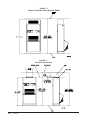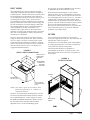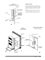
1
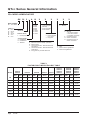
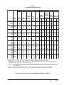
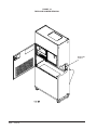
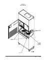
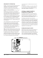
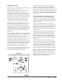
QTEC SERIES
PACKAGED HEAT PUMP
INSTALLATION
INSTRUCTIONS
Models:
QH243
QH302
QH362
QH422
QH482
QH602
Bard Manufacturing Company, Inc.
Bryan, Ohio 43506
Since 1914 . . . Moving ahead, just as planned.
© Copyright 2004
Manual:
Supersedes:
File:
Date:
2100-420H
2100-420G
Vol II Tab 14
06-28-07
Manual 2100-420H
Page
1 of 34
CONTENTS
Getting Other Information and Publications
For more information, contact these publishers: .......... 3
QTEC General Information
QTEC Model Nomenclature .......................................... 4
Shipping Damage ......................................................... 8
Unit Removal From Skid .............................................. 8
Handling Unit After Removal From Skid ....................... 9
General ......................................................................... 9
Minimum Installation Height ......................................... 9
Duct Work .................................................................. 11
Filters .......................................................................... 11
Fresh Air Intake .......................................................... 12
Condensate Drain ...................................................... 12
Service Light ............................................................... 13
Start Up
Description of Standard Equipment ............................... 21
Optional CFM (QH362, QH422, QH482 & QH602 Only) ..... 21
Important Installer Note .................................................. 21
Phase Monitor ................................................................ 21
Three Phase Scroll Compressor Start Up
Information ................................................................ 21
Service Hints .................................................................. 22
Mist Eliminator Service .................................................. 22
Vent Options .................................................................. 23
Sequence of Operation .................................................. 26
Optional Climate Controls Sequence
of Operation .............................................................. 26
Pressure Service Ports .................................................. 26
Defrost Cycle ................................................................. 27
Installation Instructions
Mounting the Unit ....................................................... 14
Wiring — Main Power ................................................. 15
Wiring — Low Voltage Wiring ..................................... 15
Low Voltage Connections ........................................... 16
Troubleshooting
Solid State Heat Pump Control Troubleshooting
Procedure ...................................................................... 29
Checking Temperature Sensor ...................................... 29
Troubleshooting GE ECM™ Blower Motors ............. 30-31
Fan Blade Setting Dimensions ...................................... 32
Refrigerant Charge ........................................................ 32
Pressure Charts ...................................................... 33 - 34
Figures
Tables
Figure 1
Figure 2
Figure 3
Figure 4
Figure 5
Figure 6
Figure 7
Figure 8
Figure 9
Figure 10
Figure 11
Figure 12
Figure 13
Figure 14
Figure 15
Figure 16
Figure 17
Figure 18
Figure 19
Figure 20
Figure 21
Figure 22
Figure 23
Figure 24
Figure 25
Figure 26
Unit Dimensions .......................................... 7
Air Seal on Bottom of Unit ........................... 8
Removal of Unit From Skid ......................... 8
Unit on Appliance Cart for Moving ............... 9
Installation With Free Blow Plenum .......... 10
Ducted Application ..................................... 10
Supply Duct Connections .......................... 11
Filter Location ............................................ 11
Optional Side Drain ................................... 12
Standard Rear Drain .................................. 12
Rear Drain (Top View) ............................... 13
Unit Mounting ............................................ 13
Removing Locking Screws from Wheels ... 14
Component Location ................................. 15
Thermostat Plug Terminals ........................ 17
Thermostat Wiring Diagram "X" Option .... 18
Thermostat Wiring Diagram "A" Option .... 19
Thermostat Wiring Diagram "D" Option ... 20
Fresh Air Damper Removal ....................... 24
QERV Removal ......................................... 25
Heat Pump Control Board ......................... 26
Low Pressure Control Bypass Timer ......... 27
Control Disassembly ................................. 31
Winding Test .............................................. 31
Drip Loop ................................................... 31
Fan Blade Setting ...................................... 32
Manual 2100-420H
Page
2 of 34
Table 1
Table 2
Table 2A
Table 3
Table 4
Table 5
Table 6
Factory Built-In Electric Heat Table .............. 4
Electrical Specifications ................................ 5
Electrical Specifications ................................ 6
Operating Voltage Range ........................... 15
Wall Thermostats ........................................ 17
Troubleshooting .......................................... 28
Temperature vs Resistance of
Temperature Sensor ................................... 29
Table 7 Fan Blade Dimensions ............................... 32
Table 8 Super Heat at Compressor ......................... 32
Table 9 Indoor Blower Performance ........................ 32
Table 10 Cooling Pressure ........................................ 33
Table 11 Heating Pressure ........................................ 34
GETTING OTHER INFORMATION AND PUBLICATIONS
These publications can help you install the air
conditioner or heat pump. You can usually find these at
your local library or purchase them directly from the
publisher. Be sure to consult current edition of each
standard.
FOR MORE INFORMATION, CONTACT
THESE PUBLISHERS:
ACCA
Air Conditioning Contractors of America
1712 New Hampshire Avenue
Washington, DC 20009
Telephone: (202) 483-9370
Fax: (202) 234-4721
ANSI
American National Standards Institute
11 West Street, 13th Floor
New York, NY 10036
Telephone: (212) 642-4900
Fax: (212) 302-1286
National Electrical Code ..................... ANSI/NFPA 70
Standard for the Installation ............. ANSI/NFPA 90A
of Air Conditioning and Ventilating Systems
Standard for Warm Air ...................... ANSI/NFPA 90B
Heating and Air Conditioning Systems
Load Calculation for ....................... ACCA Manual J or
Winter and Summer
Manual N
Air Conditioning
Low Pressure, Low Velocity ........ ACCA Manual D or
Duct System Design
Manual Q
Winter and Summer Air Conditioning
ASHRAE American Society of Heating, Refrigeration,
and Air Conditioning Engineers, Inc.
1791 Tullie Circle, N.E.
Atlanta, GA 30329-2305
Telephone: (404) 636-8400
Fax: (404) 321-5478
NFPA
National Fire Protection Association
Batterymarch Park
P.O. Box 9101
Quincy, MA 02269-9901
Telephone: (800) 344-3555
Fax: (617) 984-7057
Manual
Page
2100-420H
3 of 34
QTEC Series General Information
QTEC MODEL NOMENCLATURE
QH
36
2 – A
MODEL NUMBER |
QH - QTEC Model
CAPACITY |
24 - 2 Ton
30 - 2½ Ton
36 - 3 Ton
42 - 3½ Ton
48 - 4 Ton
60 - 5 Ton
REVISION |
SPECIAL UNITS |
L - Low Ampacity Circuit
VOLTS & PHASE |
A - 230/208/60/1
B - 230/208/60/3
C - 460/60/3
10
X
KW
0Z - 0KW
05 - 5KW
06 - 6KW
09 - 9KW
10 - 10KW
12 - 12KW
15 - 15KW
X
X
X
FILTER OPTIONS
X - 1-Inch Fiberglass
(Standard)
F - 2-Inch Fiberglass
P - 2-Inch Pleated
X
COIL OPTIONS
X - Standard
INTERNAL CONTROLS
X - Standard
• High Pressure Switch
• Low Pressure Switch
• Compressor Time Delay
E - Low Ambient Control
Q - Outdoor Thermostat
R - Low Ambient Control &
Outdoor Thermostat
COLOR OPTIONS
V - Platinum w/Slate
Front (Vinyl)
4 - Gray paint
VENTILATION OPTIONS
X - Barometric Fresh Air Damper (Standard)
B - Blank-off Plate
V - Commercial Ventilator - Motorized w/Exhaust
Spring Return
P - Commercial Ventilator - Motorized w/Exhaust
Power Return
R - Energy Recovery Ventilator w/Exhaust
X
CLIMATE CONTROL OPTIONS
X - None
A - Electronic/Non Prog/Man C/O
D - Electronic/Prog/Man/Auto
TABLE 1
FACTORY BUILT-IN ELECTRIC HEAT TABLE
Models
QH243-A
QH302-A
QH362-C
QH422-C
QH482-C
QH602-C
QH302-C
240V-1 208V-1 240V-1 208V-1 240V-1 208V-1
480V-3
480V-3
240V-1 208V-1 240V-1 208V-1
480V-3
KW
B TU H
B TU H
B TU H
B TU H
5.0
16,380 12,290
B TU H
B TU H
QH302-B
QH362-B
QH422-B
QH482-B
QH602-B
QH243-C
B TU H
QH243-B
QH362-A
QH422-A
QH482-A
QH602-A
B TU H
B TU H
B TU H
B TU H
B TU H
B TU H
16,380 12,290
6.0
20,500
15,360
20,500
20,500
20,500
15,360
20,500
9.0
30,700 23,000 30,700 23,000
30,700
30,700
30,700 23,000
30,700
10.0
15,360 20,500
32,670 24,570
12.0
15.0
Manual 2100-420H
Page
4 of 34
32,670 24,570
41,000
30,700
41,000
49,150
36,860 49,150
36,860
49,150
TABLE 2
ELECTRICAL SPECIFICATIONS
SINGLE CIRCUIT
3
MODELS
RATED
VOLTS &
PHASES
1
DUAL CIRCUIT
2
3
2
2
1
MINIMUM
MAXIMUM
CIRCUIT
EXTERNAL FIELD
AMPACITY
NO.
MINIMUM
FUSE OR POWER GROUND
FIELD
CIRCUIT
WIRE
CIRCUIT
CKT CKT
WIRE
POWER
SIZE
A
B
SIZE
CIRCUITS AMPACITY BREAKER
2
MAXIMUM
EXTERNAL
FIELD
FUSE OR
POWER
CIRCUIT
BREAKER WIRE SIZE
CKT
A
CKT
B
GROUND
WIRE SIZE
CKT CKT CKT CKT
A
B
A
B
QH243-A0Z
-A05 230/208-1
-A10
1
1
1 OR 2
22
47
72
30
50
80
10
8
4
10
10
8
--22
--50
--30
--50
--10
--8
--10
--10
QH243-B0Z
-B06 230/208-3
-B09
1
1
1
17
35
44
20
35
45
12
8
8
12
10
10
----
----
----
----
----
----
----
----
QH243-C0Z
-C06
-C09
1
1
1
8
17
22
15
20
25
14
12
10
14
12
10
----
----
----
----
----
----
----
----
QH302-A0Z
-A05 230/208-1
-A10
1
1
1 OR 2
24
49
74
35
50
80
8
8
4
10
10
8
--24
--50
--30
--50
--10
--8
--10
--10
QH302-B0Z
-B06
230/208-3
-B09
-B12
1
1
1
1
18
36
45
54
25
40
45
60
10
8
8
6
10
10
10
10
-----
-----
-----
-----
-----
-----
-----
-----
QH302-C0Z
-C06
-C09
-C12
1
1
1
1
9
18
23
27
15
20
25
30
14
12
10
10
14
12
10
10
-----
-----
-----
-----
-----
-----
-----
-----
QH362-A0Z
-A05
230/208-3
-A10
4 -A15
1
1
1 OR 2
1 OR 2
29
54
79
82
45
60
90
90
8
6
4
4
10
10
8
8
--29
32
--50
50
--40
40
--50
50
--8
8
--8
8
--10
10
--10
10
QH362-B0Z
-B06
230/208-3
-B09
5 -B15
1
1
1
1
23
41
50
52
30
45
50
60
10
8
8
6
10
10
10
10
-----
-----
-----
-----
-----
-----
-----
-----
QH362-C0Z
-C06
-C09
5 -C15
1
1
1
1
11
20
24
26
15
20
30
30
14
12
10
10
14
12
10
10
-----
-----
-----
-----
-----
-----
-----
-----
460-3
460-3
460-3
1 Maximum size of the time delay fuse or HACR type circuit breaker for protection of field wiring conductors.
2 Based on 75°C copper wire. All wiring must conform to the National Electrical Code and all local codes.
3 These “Minimum Circuit Ampacity” values are to be used for sizing the field power conductors. Refer to the National Electric
Code (latest revision), article 310 for power conductor sizing.
CAUTION:
When more than one field power conductor circuit is run through one conduit, the conductors must be derated. Pay
special attention to Note 8 of Table 310 regarding Ampacity Adjustment Factors when more than three conductors
are in a raceway.
4 Maximum KW that can operate with heat pump on is 10KW. Other 5KW energizes during emergency heating only.
5 Maximum KW that can operate with heat pump on is 9KW. Other 6KW energizes during emergency heating only.
ELECTRICAL SPECIFICATIONS CONTINUED ON PAGE 6 TABLE 2A
Manual
Page
2100-420H
5 of 34
TABLE 2A
ELECTRICAL SPECIFICATIONS
(Continued)
SINGLE CIRCUIT
3
MODEL
RATED
VOLTS &
PHASE
1
DUAL CIRCUIT
2
MAXIMUM
NO.
EXTERNAL FIELD
MINIMUM
FIELD
FUSE OR POWER
CIRCUIT
POWER
WIRE
CIRCUIT
CIRCUITS AMPACITY BREAKER
SIZE
2
GROUND
WIRE
SIZE
3
1
2
2
MINIMUM
CIRCUIT
AMPACITY
MAXIMUM
EXTERNAL
FUSE OR
CIRCUIT
BREAKER
FIELD
POWER
WIRE SIZE
GROUND
WIRE SIZE
CKT CKT
A
B
CKT
A
CKT
B
CKT
A
CKT
B
CKT
A
CKT
B
QH422-A0Z
-A05
230/208-1
-A10
4 -A15
1
1
1 OR 2
1 OR 2
33
58
83
83
50
60
90
90
8
6
4
4
10
10
8
8
--33
33
--50
50
--40
40
--50
50
--8
8
--8
8
--10
10
--10
10
QH422-B0Z
-B06
230/208-3
-B09
5 -B15
1
1
1
1
24
43
52
52
30
50
60
60
10
8
6
6
10
10
10
10
-----
-----
-----
-----
-----
-----
-----
-----
QH422-C0Z
-C06
-C09
5 -C15
1
1
1
1
12
21
26
26
15
25
30
30
14
10
10
10
14
10
10
10
-----
-----
-----
-----
-----
-----
-----
-----
QH482-A0Z
-A05
230/208-1
-A10
4 -A15
1
1
1 OR 2
1 OR 2
36
61
86
86
50
70
90
90
8
6
3
3
10
8
8
8
-36
36
36
-25
50
50
-50
50
50
-25
50
50
-8
8
8
-10
8
8
-10
10
10
-10
10
10
QH482-B0Z
-B06
230/208-3
-B09
5 -B15
1
1
1
1
26
44
53
53
40
50
60
60
8
8
6
6
10
10
10
10
-----
-----
-----
-----
-----
-----
-----
-----
QH482-C0Z
-C06
-C09
5 -C15
1
1
1
1
14
23
27
27
15
25
30
30
14
10
10
10
14
10
10
10
-----
-----
-----
-----
-----
-----
-----
-----
QH602-A0Z
-A05
230/208-1
-A10
4 -A15
1
1 or 2
1 or 2
1 or 2
46
71
96
96
60
80
110
110
8
4
3
3
10
8
6
6
-46
46
46
-25
50
50
-60
60
60
-25
50
50
-8
8
8
-10
8
8
-10
10
10
-10
10
10
QH602-B0Z
-B09 230/208-3
5 -B15
1
1
1
31
58
58
45
70
70
8
6
6
10
8
8
----
----
----
----
----
----
----
----
QH602-C0Z
-C09
5 -C15
1
1
1
17
30
30
25
35
35
10
8
8
10
10
10
----
----
----
----
----
----
----
----
460-3
460-3
460-3
1 Maximum size of the time delay fuse or HACR type circuit breaker for protection of field wiring conductors.
2 Based on 75°C copper wire. All wiring must conform to the National Electrical Code and all local codes.
3 These “Minimum Circuit Ampacity” values are to be used for sizing the field power conductors. Refer to the National Electric
Code (latest revision), article 310 for power conductor sizing.
CAUTION:
When more than one field power conductor circuit is run through one conduit, the conductors must be derated. Pay
special attention to Note 8 of Table 310 regarding Ampacity Adjustment Factors when more than three conductors
are in a raceway.
4 Maximum KW that can operate with heat pump on is 10KW. Other 5KW energizes during emergency heating only.
5 Maximum KW that can operate with heat pump on is 9KW. Other 6KW energizes during emergency heating only.
Manual 2100-420H
Page
6 of 34
FIGURE 1
UNIT DIMENSIONS
Manual
Page
2100-420H
7 of 34
SHIPPING DAMAGE
Upon receipt of equipment, the carton should be
checked for external signs of shipping damage. The
skid must remain attached to the unit until the unit is
ready for installation. If damage is found, the receiving
party must contact the last carrier immediately,
preferably in writing, requesting inspection by the
carrier’s agent.
FIGURE 2
AIR SEAL UNDER QTEC UNIT
UNIT REMOVAL FROM SKID
WARNING
This unit is heavy and requires more than one
person to handle and remove from the skid.
Check unit wheels to ensure that wheels are
locked before removing from skid. Extreme
caution must be taken to prevent injury to
personnel and damage to the unit.
It is recommended that the unit not be removed from the
skid with a forklift since the air seal under the unit could
be damaged. See Figure 2.
The shipping brackets on each side of the unit must be
removed and discarded. See Figure 3-A. The return air
grille panel can be removed to provide a place to hold
the unit. The unit can be slid forward on the skid until
Air Seal
the front wheels hang over the edge of the skid. See
Figure 3-B. The unit can be tipped forward and slid
down the edge of the skid until the front wheels touch
the ground. See Figure 3-C. The wheels will not roll.
They are shipped from the factory locked so they will
not roll. The back of the skid will have to be held down
to keep it from tipping up. The skid can be slid out from
under the unit. The unit can then be set upright.
FIGURE 3
REMOVAL OF UNIT FROM SKID
Hold
Skid
Down
A Shipping Brackets
Manual 2100-420H
Page
8 of 34
B Front Wheels Over Edge
C Front Wheels On Floor
HANDLING UNIT AFTER REMOVAL
FROM SKID
WARNING
Exercise extreme caution when pushing the
unit on the rollers. Handle and push from the
lower 1/3 of the unit. Insure that debris is not
on the floor where the unit is to be moved on
the rollers. Failure to do so could result in the
unit tipping over and causing bodily injury and/
or damage to the unit.
The unit will have to be turned sideways and removed
from the skid to fit through a 36" doorway. If the door
height allows, the unit can be slid sideways through the
door.
If the unit can not be slid through the door, then the unit
will have to be put on a cart and tipped down to roll
through the door. It is recommended that an appliance
cart by used with a strap to hold the unit on the cart.
The wheels of the unit must be locked. If the wheels
were allowed to roll, the unit could roll off the cart. The
unit should always be carted from the left side. This is
the side where the compressor is located. See Figure 4.
The blade of the appliance cart should be slid under the
wheels of the unit. The strap of the appliance cart
should be placed around the unit and strapped tightly.
Help will be required to tip the unit back onto the cart.
The unit can be leaned far enough back to be rolled
through the door. Be careful when setting the unit back
up to keep from damaging the unit.
GENERAL
The equipment covered in this manual is to be installed
by trained, experienced service and installation
technicians.
The unit is designed for use with or without duct work.
For use without duct work, Plenum Box QPB42 is
recommended.
These instructions explain the recommended method to
install the air cooled self-contained unit and the
electrical wiring connections to the unit.
These instructions and any instructions packaged with
any separate equipment required to make up the entire
air conditioning system should be carefully read before
beginning the installation. Note particularly “Start
Procedure” and any tags and/or labels attached to the
equipment.
While these instructions are intended as a general
recommended guide, they do not supersede any national
and/or local codes in any way. Authorities having
jurisdiction should be consulted before the installation is
made. See Page 3 for information on codes and
standards.
FIGURE 4
UNIT ON APPLIANCE CART
QTEC UNIT
(Right Side)
STRAP
Size of unit for a proposed installation should be based
on heat loss calculation made according to methods of
Air Conditioning Contractors of America (ACCA). The
air duct should be installed in accordance with the
Standards of the National Fire Protection Systems of
Other Than Residence Type, NFPA No. 90A, and
Residence Type Warm Air Heating and Air
Conditioning Systems, NFPA No. 90B. Where local
regulations are at a variance with instructions, installer
should adhere to local codes.
APPLIANCE
CART
MINIMUM INSTALLATION HEIGHT
The minimum installation height of the unit with a Free
Blow Plenum is 8 ft. 6 in. This provides enough
clearance for the plenum to be removed. See Figure 5.
COMPRESSOR
The minimum installation height for ducted applications
is 8 ft. 4½ in. This provides enough clearance to install
the duct work. See Figure 6.
Manual
Page
2100-420H
9 of 34
FIGURE 5
INSTALLATION WITH FREE BLOW PLENUM
FIGURE 6
DUCTED APPLICATION
Manual 2100-420H
Page
10 of 34
DUCT WORK
Any heat pump is more critical of proper operating
charge and an adequate duct system than a straight air
conditioning unit. All duct work must be properly sized
for the design airflow requirement of the equipment.
Air Conditioning Contractors of America (ACCA) is an
excellent guide to proper sizing. All duct work or
portions thereof not in the conditioned space should be
properly insulated in order to both conserve energy and
prevent condensation or moisture damage. When duct
runs through unheated spaces, it should be insulated
with a minimum of one inch of insulation. Use
insulation with a vapor barrier on the outside of the
insulation. Flexible joints should be used to connect the
duct work to the equipment in order to keep the noise
transmission to a minimum.
The QTEC series heat pump has provision to attach a
supply air duct to the top of the unit. Duct connection
size is 12 inches x 20 inches. The duct work is field
supplied and must be attached in a manner to allow for
ease of removal when it becomes necessary to slide the
unit out from the wall for service. See Figure 7 for
suggested attachment method.
FIGURE 7
SUPPLY DUCT CONNECTIONS
SUPPLY DUCT
TO BE FIELD
SUPPLIED
For hot water coil option a QPBHWxx-F for free blow
or QPBHWxx-D for ducted airflow is used
When used with a ducted supply, a QCX Cabinet
Extension can be used to conceal the duct work above
the unit to the ceiling. This extends 20" above the unit
for a total height above the floor of 10'-7/8". The unit is
equipped with a variable speed indoor blower motor
which increases in speed with an increase in duct static
pressure. The unit will therefore deliver proper rated air
flow up to the maximum ESP shown in Table 9.
However, for quiet operation of the air system, the duct
static should be kept as low as practical, within the
guidelines of good duct design.
FILTERS
Two 1-inch throw away filters [(1) 16x16 and (1)
16x20] are supplied with each unit. The filters slide into
filter brackets. Refer to Figure 8.
The filters are serviced from the inside of the building
by opening the hinged door. This door is attached by
1/4 turn fasteners and one locking latch.
The internal filter brackets are adjustable to
accommodate 2-inch filters. The tabs for the 1-inch
filters must be bent down to allow the 2-inch filters to
slide in place.
FIGURE 8
FILTER LOCATION
ATTACHMENT
SCREWS TO
BE FIELD
SUPPLIED
FILTERS
ROOM SIDE
OF QTEC UNIT
DUCT FLANGE
PROVIDED WITH
UNIT
NOTE: Unit cabinet, supply air duct and free blow
plenum are approved for “0” clearance to
combustible material.
The QTEC series heat pumps are designed for use with
free return (non-ducted) and either free blow with the
use of QPB Plenum Box or a duct supply air system.
The QPB and QPBHW Plenum Box mounts on top of
the unit and has both vertically and horizontally
adjustable louvers on the front discharge grille.
RETURN AIR
GRILLE
Manual
Page
2100-420H
11 of 34
FRESH AIR INTAKE
CONDENSATE DRAIN
This unit is equipped with a fresh air damper assembly.
The damper blade is locked in the closed position when
the unit is shipped from the Factory. To allow the
damper to operate remove the two plastic locking pins,
one on each end of the blade. This will allow for
maximum fresh airflow. The damper blade will now
open when the indoor blower is operating. If less than
maximum fresh airflow is required, reinsert the plastic
pins to limit damper blade opening to desired level.
Two extra pins are provided (taped to the inside of the
assembly) which may be used to hold the blade in some
position other than minimum or maximum position.
This fresh air assembly is located in the rear of the unit
and to gain access to make these adjustments remove
the air filter service door.
There are two drain connections on the unit. The rear
drain is the primary drain, and is located on the right
lower rear panel of the unit. The optional side drain is
located on the bottom right side of the unit. The side
drain is shipped with a plug installed.
All capacity, efficiency and cost of operation
information as required for Department of Energy
“Energyguide” Fact Sheets are based upon the fresh air
blank-off plate in place and is recommended for
maximum energy efficiency.
The blank-off plate is available upon request from the
factory and is installed in place of the fresh air damper
shipped with each unit.
For details on energy recovery ventilation see separate
section.
FIGURE 9
OPTIONAL SIDE DRAIN (SIDE VIEW)
INSTALLATION
The side drain requires a water trap for proper drainage.
See Figure 9. The drain can be routed through the floor
or through the wall. If the drain is to be routed
through an unconditioned space, it must be protected
from freezing. The drain line must be able to be
removed from the unit if it is necessary to remove the
unit from the wall. When the side drain is used, the
plug must be removed and installed in the rear drain
outlet.
The rear drain can be used with wall thickness of up to
10 inches where a water trap can be installed between
the unit and the interior wall. See Figure 10. The trap
cannot extend beyond the edge of the unit or it will
interfere with the wall mounting bracket. The drain can
be routed through the floor or through the wall. If the
drain is routed through the wall, the drain line must be
positioned such that it will not interfere with the sleeve
flange or the grille. See Figure 11. If the drain is to be
routed through an unconditioned space, it must be
protected from freezing.
Optional rear drain kits, both standard and heated
versions, are available to facilitate easy installation, and
also removability of heat pump for service. The
standard version provides a connection that allows the
evaporator condensate to drain independently bypassing
the lower drain pan. Note that on models equipped with
a refrigerant subcooler in the lower drain pan may
experience a slight decrease in cooling performance and
efficiency.
QTEC UNIT
FIGURE 10
STANDARD REAR DRAIN
Manual 2100-420H
Page
12 of 34
FIGURE 11
REAR DRAIN (TOP VIEW)
SERVICE LIGHT
The unit is equipped with a service light which
signals the user that service is required. The light
is located in the upper control panel and is visible
only when the hinged service/filter access door is
open.
DRAIN LINE
WALL (MAXIMUM 10"
FOR REAR DRAIN)
SLEEVE
The Service Unit light indicates that the unit has
been shut off by a high or low pressure device.
This indicates that the unit needs to be serviced.
COUPLINGS NOT
SHOWN BUT
RECOMMENDED
FOR EASE OF
REMOVABILITY
FOR SERVICE.
WALL
BRACKET
WATER
TRAP
UNIT
FIGURE 12
UNIT MOUNTING
SIDE TRIM
(2 PCS.)
ENLARGED VIEW OF MOUNTING
BRACKET SHOWING SLEEVE TO
CABINET ATTACHMENT
MOUNTING BRACKET
WALL
SLEEVE
SIDE TRIM
(2 PCS.)
#8 SCREW
PROVIDED
(LIGHT COLOR)
MOUNTING
BRACKET
CABINET
SIDE PANEL
#10 HEX
HEAD SCREW
PROVIDED
BOTTOM
TRIM
PIECE
BOTTOM TRIM
EXTENSION
Manual
Page
2100-420H
13 of 34
INSTALLATION INSTRUCTIONS
MOUNTING THE UNIT
When installing a QTEC unit near an interior wall on the
left side, a minimum of 8 inches is required; 12 inches is
preferred.
When installing a QTEC unit near an interior wall on the
right side, a minimum of 18 inches is required as
additional space is required to connect the side drain. If
the rear condensate drain kit QCDS48 is used the
minimum can be reduced to 8 inches.
This clearance is required to allow for the attachment of
the unit to the sleeve and side trim pieces to the wall.
This unit is to be secured to the wall sleeve with
mounting brackets provided. The unit itself, the supply
duct and the free blow plenum are suitable of “0”
clearance to combustible material.
Following are the steps for mounting the QTEC, for
reference see Figure 12 (page 13).
1. Attach mounting brackets to the wall sleeve with
screws provided.
2. Position the unit in front of the sleeve with the
condenser section toward the sleeve.
3. Remove the locking screws from the wheels.
Refer to Figure 13.
4. Roll the unit into the sleeve. Make sure to check
both sides of the unit as it is being rolled to keep
it centered in the sleeve. Also check the
alignment to the mounting brackets. This unit
must be level from side to side. If adjustments
are necessary, shim up under the rollers with
sheets of steel or any substance that is not
affected by moisture.
5. Make sure the gasket on the rear of the unit is
touching the sleeve across the top and down both
sides. This is a rain water seal.
6. Secure the mounting brackets to the unit with
screws provided, #10 hex head sheet metal
screws.
7. Bottom trim extensions are provided for use when
wall is less than 14 inches but greater than 10.5
inches. Secure to wall with screws (not
provided).
8. Attach the bottom trim piece to the unit with the
screws provided (dark colored).
9. Position side trim pieces to wall and attach with
field supplied screws. There are two long pieces
and two short pieces supplied. The long pieces
are to enclose the gap behind the unit. The short
pieces are to fill the gap behind the cabinet
extension or the free blow plenum box. The may
be cut to suit your ceiling height or overlap the
unit side trim. There is sufficient length to trip up
to a 10'2" ceiling.
NOTE: If the exterior wall thickness is between 5
inches to 10.5 inches, a side trim extension
piece kit, model QSTX42, is available.
FIGURE 13
REMOVING LOCKING SCREWS FROM WHEELS
REMOVE SCREWS FROM
WHEELS BEFORE
ROLLING INTO PLACE
Manual 2100-420H
Page
14 of 34
WIRING – MAIN POWER
Refer to the unit rating plate and/or Table 2 for wire
sizing information and maximum fuse or “HACR Type”
circuit breaker size. Each unit is marked with a
“Minimum Circuit Ampacity”. This means that the
field wiring used must be sized to carry that amount of
current. Depending on the installed KW of electric
heat, there may be two field power circuits required. If
this is the case, the unit serial plate will so indicate. All
models are suitable only for connection with copper
wire. Each unit and/or wiring diagram will be marked
“Use Copper Conductors Only”. These instructions
MUST BE adhered to. Refer to the National Electrical
Code (NEC) for complete current carrying capacity data
on the various insulation grades of wiring material. All
wiring must conform to NEC and all local codes.
The electrical data lists fuse and wire sizes (75°C
copper) for all models, including the most commonly
used heater sizes. Also shown are the number of field
power circuits required for the various models with
heaters.
The unit rating plate lists a “Maximum Time Delay
Relay Fuse” or “HACR Type” circuit breaker that is to
be used with the equipment. The correct size must be
used for proper circuit protection, and also to assure that
The disconnect access door on this unit may be locked
to prevent unauthorized access to the disconnect.
See Start Up section for information on three phase
scroll compressor start-ups.
The field wiring connections are located behind the top
and hinged panel in the circuit breaker panel. See
Figure 14.
WIRING – LOW VOLTAGE WIRING
230/208V, 1 PHASE AND 3 PHASE EQUIPMENT
DUAL PRIMARY VOLTAGE TRANSFORMERS.
All Equipment leaves the factory wired on 240V tap.
For 208V operation, reconnect from 240V to 208V tap.
The acceptable operating voltage range for the 240 and
208V taps are as noted in Table 3.
TABLE 3
OPERATING VOLTAGE RANGE
TAP
RANGE
240V
253 – 216
208V
220 – 187
NOTE: The voltage should be measured at the filed
power connection point in the unit and while
the unit is operating at full load (maximum
amperage operating condition).
FIGURE 14
COMPONENT LOCATION
SIDE FIELD WIRE
ENTRANCE
ELECTRIC
HEATERS
UNIT
MOUNTED
THERMOSTAT
LOCATION
there will be no nuisance tripping due to the momentary
high starting current of the compressor motor.
REMOTE
THERMOSTAT
TERMINAL
BLOCK
INDOOR
BLOWER
DEHUMIDIFICATION
CONTROL
(OPTIONAL)
CIRCUIT
BREAKER PANEL
& CONTROLS
LOWER
CONTROL
PANEL
The standard Climate Control Option X is a remote
thermostat connection terminal block. See Figure 16 for
wiring diagram. Compatible thermostats are listed in
Table 4.
The Climate Control Option A is an electronic, nonprogrammable manual or auto changeover thermostat.
The subbase of the thermostat is factory wired to the
front panel of the unit. See Figure 17 for wiring
diagram. Compatible for use with Bard CS2000A1
Controller and Energy Recovery Ventilator.
The Climate Control Option D is an electronic,
programmable thermostat. The subbase of the
thermostat is factory wired to the front panel of the unit.
See Figure 18 for wiring diagram. Compatible for use
with Energy Recovery Ventilator or Economizer.
NOTE: On option X or A the CS2000A1 (or other field
provided means to control ventilation) must be
used if any of the motorized ventilation options
are installed.
Manual
Page
2100-420H
15 of 34
LOW VOLTAGE CONNECTIONS
These units use a grounded 24 volt AC low voltage
circuit.
The “R” terminal is the hot terminal and the “C”
terminal is grounded.
“G” terminal or pins 6 and 1 of P2 are the fan inputs.
Both must be energized for proper fan operation. This
is done automatically in the factory installed climate
control options. If the climate control option is
abandoned and connections are made directly to P2 both
pins 6 and 1 of P2 must be energized for proper
operation.
“Y” terminal or pin 7 of P2 is the compressor input.
“B” terminal or pin 8 of P2 is the reversing valve input.
The reversing valve must be energized for heating
mode.
“R” terminal or pin 10 of P2 is 24 VAC hot.
“C” terminal or pin 11 of P2 is 24 VAC grounded.
“L” terminal or pin 12 of P2 is compressor lockout
output. This terminal is activated on a high or low
pressure trip by the electronic heat pump control. This
is a 24 VAC output.
“W2” terminal or pin 9 of P2 is second stage heat (if
equipped). If the unit is equipped with an optional hot
water coil plenum box or electric heat these will be
energized by this terminal.
“O1” terminal of pin 5 of P2 is the ventilation input.
This terminal energizes any factory installed ventilation
option.
“E” terminal or pin 3 of P2 is the emergency heat input.
This terminal energizes the emergency heat relay.
NOTE: For total and proper control using DDC, a total
of 6 controlled outputs are required (5 if no
ventilation system is installed). For proper
system operation under Emergency Heat
conditions. Where the compressor needs to be
deactivated, the B-W2-E outputs need to be
energized. Removing the Y (compressor) signal
alone turns the compressor off, but does not
activate the additional circuitry embedded in
the heat pump for proper and complete
operation.
LOW VOLT AGE CONNECT IONS FOR
DDC CONT ROL
Fan Only
Energize G
Cooling Mode
Energize Y, G
Heat Pump Heating
Energize Y, G, B
2nd Stage Heating
(if employed)
Energize G, W2
Ventilation
Energize G, O1
Emergency Heat
Energize B, W2, E
GENERAL
This unit is equipped with a variable speed ECM motor.
The motor is designed to maintain rated airflow up to
the maximum static allowed. It is important that the
blower motor plugs are not plugged in or unplugged
while the power is on. Failure to remove power prior
to unplugging or plugging in the motor could result in
motor failure.
CAUTION
Do not plug in or unplug blower motor
connectors while the power is on. Failure to do
so may result in motor failure.
Manual 2100-420H
Page
16 of 34
TABLE 4
WALL THERMOSTATS
Thermostat
Predominant Features
8403-060
(1120-445)
3 stage Cool; 3 stage Heat
Programmable/Non-Programmable Electronic
HP or Conventional
Auto or Manual changeover
2 stage Cool; 2 stage Heat
8403-058
Electronic Non-Programmable
(TH5220D1151)
Auto or Manual changeover
FIGURE 15
MIS-1285
Manual
Page
2100-420H
17 of 34
FIGURE 16
REMOTE THERMOSTAT WIRING DIAGRAM
“X” THERMOSTAT OPTION
VENTILATOR OR DAMPER
NOTE: On option X or A the CS2000A1 (or other field
provided means to control ventilation) must be
used if any of the motorized ventilation options
are installed.
Manual 2100-420H
Page
18 of 34
FIGURE 17
UNIT MOUNTED THERMOSTAT WIRING DIAGRAM
“A” THERMOSTAT OPTION
NOTE: On option X or A the CS2000A1 (or other field
provided means to control ventilation) must be used
if any of the motorized ventilation options are
installed.
Manual
Page
2100-420H
19 of 34
FIGURE 18
UNIT MOUNTED THERMOSTAT WIRING DIAGRAM
“D” THERMOSTAT OPTION
Manual 2100-420H
Page
20 of 34
START UP
DESCRIPTION OF STANDARD
EQUIPMENT
Solid State Electronic Heat Pump Control
Provides efficient 30-minute defrost cycle. A thermistor
sensor and speed up terminal for service along with a
10- minute defrost override are standard on the
electronic heat pump control.
High / Low Pressure Switch
Provides refrigerant circuit high pressure and loss of
charge protection. Includes lockout circuit that is
resettable from room thermostat.
Five Minute Compressor Time Delay
Provides short cycle protection for the compressor
which extends compressor life. Built into the electronic
heat pump control as standard.
Service Lights
One service light indicates when service is required.
• Check System – detects high or low pressure
switch operation for compressor protection.
OPTIONAL CFM (QH362, QH422, QH482
AND QH602 ONLY)
These units are shipped from the factory set to operate at
the optional CFM level shown in Table 9. This provides
lower operating sound levels for non-ducted, free
discharge applications. This CFM level will reduce the
system capacity performance by approximately 2% at
the same energy efficiency.
Rated CFM is required for ducted applications for
maximum performance rating. To obtain full CFM on
these models, connect jumper wire as follows:
1. Disconnect all power to the unit. Failure to do so
may result in damage to the motor.
2. Open return air service panel
3. Open inner control panel cover
4. Locate low voltage terminal strip. There is a pink
jumper wire with both ends attached to terminal
marked “G2”. Move one end of this jumper to
terminal “Y”.
5. Reverse steps to reassemble.
IMPORTANT INSTALLER NOTE
For improved start-up performance, wash the indoor coil
with a dishwasher detergent.
PHASE MONITOR
All units with three phase scroll compressors are
equipped with a 3 phase line monitor to prevent
compressor damage due to phase reversal.
The phase monitor in this unit is equipped with two
LEDs. If the Y signal is present at the phase monitor
and phases are correct the green LED will light and the
compressor contactor is allowed to energize.
If phases are reversed, the red fault LED will be lit and
compressor operation is inhibited.
If a fault condition occurs, reverse two of the supply
leads to the unit. Do not reverse any of the unit factory
wires as damage may occur.
THREE PHASE SCROLL COMPRESSOR
START UP INFORMATION
Scroll compressors, like several other types of
compressors, will only compress in one rotational
direction. Direction of rotation is not an issue with
single phase compressors since they will always start
and run in the proper direction.
However, three phase compressors will rotate in either
direction depending upon phasing of the power. Since
there is a 50-50 chance of connecting power in such a
way as to cause rotation in the reverse direction,
verification of proper rotation must be made.
Verification of proper rotation direction is made by
observing that suction pressure drops and discharge
pressure rises when the compressor is energized.
Reverse rotation also results in an elevated sound level
over that with correct rotation, as well as, substantially
reduced current draw compared to tabulated values.
Verification of proper rotation must be made at the
time the equipment is put into service. If improper
rotation is corrected at this time there will be no
negative impact on the durability of the compressor.
However, reverse operation for even one hour may
have a negative impact on the bearing due to oil pump
out.
All three phase scroll compressors used in the QTEC
series are wired identically internally. As a result, once
the correct phasing is determined for a specific system
or installation, connecting properly phased power leads
to the same Fusite terminal should maintain proper
rotation direction. The direction of rotation of the motor
may be changed by reversing any two line connections
to the unit.
Manual
Page
2100-420H
21 of 34
SERVICE HINTS
1. Caution user to maintain clean air filters at all
times. Also, not to needlessly close off supply air
registers. This may reduce airflow through the
system, which shortens equipment service life as
well as increasing operating costs and noise
levels.
2. Switching to heating cycle at 75°F or higher
outside temperature may cause a nuisance trip of
the remote reset high pressure switch. Turn
thermostat off, then on to reset the high pressure
switch.
3. The heat pump wall thermostats perform multiple
functions. Be sure that all function switches are
correctly set for the desired operating mode
before trying to diagnose any reported service
problems.
4. Check all power fuses or circuit breakers to be
sure they are the correct rating.
5. Periodic cleaning of the outdoor coil to permit
full and unrestricted airflow circulation is
essential.
6. Some service requires the need to remove the unit
from the wall including replacement of the indoor
coil and/or the outdoor coil. Also, servicing the
outdoor fan motor or fan blade will require
removing the unit from the wall if the unit is
installed at a height that is not easily accessible
from the outside of the building.
In order to remove the unit from the wall the
following procedure must be used:
a. Turn off power to the unit at the remote
location. Some units may have more than one
power supply.
b. Disconnect field wiring at unit terminal block
and remove from unit.
c. Disconnect condensate drain.
d. Remove the lower skirting around the unit.
e. Remove wall mounting brackets from wall on
each side of the unit.
f. If unit is attached to duct work, remove upper
cabinet extension by removing the top center
screw only from the cabinet side panel.
Manual 2100-420H
Page
22 of 34
g. Remove screws that attach the duct work to
the unit flanges.
This unit is equipped with four rollers
mounted to the base. For ease of pulling unit
out from the wall, you may want to remove
the bottom service door which requires
removal of the return air panel, and grip the
front flange of the base pan then pull straight
out.
7. Annual maintenance is required to make sure that
all of the systems are functioning properly.
a. Check to make sure that the drains are not
obstructed in any way.
b. Remove any debris in the condenser section of
the unit.
c. Inspect and clean mist eliminator as described
below.
d. Inspect and wash outdoor coil as necessary.
MIST ELIMINATOR SERVICE
A mist eliminator is supplied with the wall sleeve. The
mist eliminator is constructed of an aluminum frame
and mesh. The mist eliminator is located in the top
section of the wall sleeve and can be removed from the
inside of the building without removing the unit from
the wall. This requires that the ventilation package must
be removed.
It is recommended that the mist eliminator be inspected
annually and serviced as required. The mist eliminator
can be inspected from the outside of the building by
looking through the outdoor grille. The mist eliminator
can be serviced from the outside by using a vacuum
cleaner. The outdoor grille must be removed. Use the
vacuum to remove dirt and debris from the surface of
the mist eliminator. If additional cleaning is required,
the mist eliminator will have to be removed from the
sleeve.
The ventilation package will have to be removed to gain
access to the mist eliminator. If the blank off plate
option is used, it is not necessary to service the mist
eliminator. The steps necessary to remove each of the
vent options are listed on the following pages.
The mist eliminator can be cleaned by washing with
soap and water. The excess water should be shaken off
the mist eliminator before it is reinstalled.
VENT OPTIONS
BAROMETRIC FRESH AIR DAMPER
(Standard)
Before starting, make sure the power has been turned
off. The return air grille panel must be removed. The
fresh air damper assembly can be seen on the back of
the unit. See Figure 19.
QTEC R ENERGY RECOVERY VENTILATOR
(Option)
Before starting, make sure that the power has been
turned off. The return air grille panel must be removed.
The energy recovery ventilator (QERV) can be seen
after the panel has been removed. To gain access to the
mist eliminator, the QERV must be removed. See
Figure 20.
1. The fresh air damper is attached to the back of
the unit with one screw on either side of the
assembly. Both of the screws must be removed.
1. The front fill plate of the QERV must be removed.
There is one screw on either side of the plate.
Remove these screws and remove the plate.
2. Once the mounting screws are removed, tilt the
assembly down and lift it out.
2. On either side of the QERV there are mounting
screws that hold the QERV in place. Remove both of
these screws.
The mist eliminator can be seen through the opening.
The mist eliminator must be raised up and the bottom
can be pulled toward the front of the unit.
COMMERCIAL ROOM VENTILATOR (Option)
Before starting, make sure the power has been turned
off. The return air grille panel must be removed. The
commercial room ventilator (CRV) can be seen after
the panel has been removed. The CRV must be
removed to gain access to the mist eliminator.
3. Underneath the heat recovery cassette there is a
power connector for the lower blower assembly. To
disconnect this plug, the tabs on both sides of the
plug must be squeezed to release the plug. While
squeezing the tabs, pull the plug out of the socket.
4. The QERV is plugged into the unit in the right side
of the unit. Both of these plugs must be disconnected
to remove the QERV. Squeeze the tabs on the sides
of the connector and pull straight out.
1. The two mounting screws in the front of the
CRV must be removed.
5. Slide the QERV assembly straight out of the unit,
being careful not to let the cassette slide out of the
QERV.
2. The power connectors for the CRV (located on
the right side of the unit) must be disconnected.
Squeeze the tabs on the sides of the connector
and pull straight out. Unplug both of the
connectors.
The mist eliminator can be seen through the opening in
the back of the unit. The mist eliminator must be raised
up and the bottom can be pulled toward the front of the
unit and removed.
3. Slide the CRV straight out of the unit.
The mist eliminator can be seen through the opening in
the back of the unit. The mist eliminator must be raised
up and the bottom can be pulled toward the front of the
unit and removed.
Manual
Page
2100-420H
23 of 34
FIGURE 19
FRESH AIR DAMPER REMOVAL
MOUNTING
SCREW
Manual 2100-420H
Page
24 of 34
FIGURE 20
QERV REMOVAL
POWER
CONNECTORS
MOUNTING
SCREWS
LOWER
BLOWER
ASSEMBLY
POWER
CONNECTOR
FRONT FILL
Manual
Page
2100-420H
25 of 34
SEQUENCE OF OPERATION
Cooling – Circuit R-Y makes the thermostat pull in the
compressor contactor starting the compressor and
outdoor motor. The G (indoor motor) circuit is
automatically completed on any call for cooling
operation, or can be energized by manual fan switch on
subbase for constant air circulation.
Heating – A 24V solenoid coil on the reversing valve
controls heating cycle operation. Two thermostat
options, one allowing “Auto” change over from cycle to
cycle and the other constantly energizing solenoid coil
during heating season and thus eliminating pressure
equalization noise except during defrost, are to be used
on “Auto” option, a circuit is completed for R-W1 and
R-Y on each heating “on” cycle, energizing reversing
valve solenoid and pulling in compressor contactor
starting compressor and outdoor motor. R-G also makes
starting indoor blower motor. Heat pump heating cycle
now in operation.
The second option has no “Auto” change over position,
but instead energizes the reversing valve solenoid
constantly whenever the system switch on subbase is
placed in “Heat” position, the “B” terminal being
constantly energized from R. A thermostat demand for
heat completes R-Y circuit, pulling in compressor
contactor starting compressor and outdoor motor. R-G
also make starting indoor blower motor.
High / Low Pressure control provides protection for the
compressor. In the event system pressures go above 450
PSI or below 3.5 PSI in either cooling or heating mode,
the compressor will be stopped. This will activate the
red light located in the control panel. The lockout
circuit will hold compressor off line. When the system
problem is corrected, the unit operation can be restored
by turning of the main power supply off and then back
on, or reset the room thermostat. The low pressure
control has a bypass to eliminate nuisance lockout on
cold start up.
The bypass timer should be set to 200 seconds and this
is to assure there is no nuisance tripping of the lowpressure control during startup in heating mode under
cold weather conditions. See Figure 22.
OPTIONAL CLIMATE CONTROLS
SEQUENCE OF OPERATION
The Climate Control Option A is an electronic, nonprogrammable manual or auto changeover thermostat.
The thermostat may be manually set to heat or cool
mode. The thermostat will maintain the temperature set
on the thermostat in the mode in which it is set.
The Climate Control Option D is an electronic,
programmable thermostat. The thermostat can be set in
the heat, cool or automatic mode. When the thermostat
is set in the heat mode, it can heat only to maintain the
temperature set on the thermostat. When the thermostat
is set in the cool mode, it can cool only to maintain the
temperature set on the thermostat. When the thermostat
is set in the automatic mode, the thermostat can change
automatically to the heat or cool modes to maintain the
temperature set on the thermostat.
PRESSURE SERVICE PORTS
High and low pressure service ports are installed on all
units so that the system operating pressures can be
observed. Pressure curves can be found later in the
manual covering all models on both cooling and heating
cycles. It is imperative to match the correct pressure
curve to the unit by model number. Upper and lower
service doors must be attached to obtain proper reading.
FIGURE 21
HEAT PUMP CONTROL BOARD (HPC)
Manual 2100-420H
Page
26 of 34
DEFROST CYCLE
The defrost cycle is controlled by temperature and time
on the solid state heat pump control.
When the outdoor temperature is in the lower 40°F
temperature range or colder, the outdoor coil
temperature is 32°F or below. This coil temperature is
sensed by the coil sensor mounted near the bottom of
the outdoor coil. Once coil temperature reaches 30°F or
below, the coil sends a signal to the control logic of the
heat pump control and the defrost timer will start.
After 30 minutes at 30°F or below, the heat pump
control will place the system in the defrost mode.
During the defrost mode the refrigerant cycle switches
back to the cooling cycle, the outdoor motor stops,
electric heaters are energized, and hot gas passing
through the outdoor coil melts any accumulated frost.
When the temperature rises to approximately 57°F, the
coil sensor will send a signal to the heat pump control
which will return the system to heating operations
automatically.
If some abnormal or temporary condition such as a high
wind causes the heat pump to have a prolonged defrost
cycle, the heat pump control will restore the system to
heating operation automatically after 10 minutes.
There are three settings on the heat pump control – 30, 60
and 90-minute. Models are shipped wired on the 30minute setting for greatest operating economy. If special
circumstances require a change to another time, remove
wire connected to terminal 30 and reconnect to desired
terminal. Refer to Figure 21. The manufacturer’s
recommendation is for 30-minute defrost cycles.
There is a cycle speed up jumper on the control. This
can be used to reduce the time between defrost cycle
operation without waiting for time to elapse.
FIGURE 22
LOW PRESSURE CONTROL BYPASS TIMER
Use a small screwdriver or other metallic object, or
another 1/4 inch QC, to short between the SPEEDUP
terminals to accelerate the HPC timer and initiate
defrost. Be careful not to touch any other terminals with
the instrument used to short the SPEEDUP terminals. It
may take up to 10 seconds with the SPEEDUP terminals
shorted for the speedup to be completed and the defrost
cycle to start.
As soon as the defrost cycle kicks in remove the
shorting instrument from the SPEEDUP terminal.
Otherwise the timing will remain accelerated and run
through the 1-minute maximum defrost length sequence
in a matter of seconds and will automatically terminate
the defrost sequence.
There is an initial defrost jumper (sen jmp) on the
control that can be used at any outdoor ambient during
the heating cycle to simulate a 0° coil temperature. This
can be used to check defrost operation of the unit
without waiting for the outdoor ambient to fall into the
defrost region.
By placing a jumper across the SEN JMP terminals (a
1/4 inch QC terminal works best) the defrost sensor
mounted on the outdoor coil is shunted out and will
activate the timing circuit. This permits the defrost
cycle to be checked out in warmer weather conditions
without the outdoor temperature having to fall into the
defrost region.
In order to terminate the defrost test the SEN JMP
jumper must be removed. If left in place too long the
compressor could stop due to the high pressure control
opening because of high pressure condition created by
operating in the cooling mode with outdoor fan off.
Pressure will rise fairly fast as there is likely no actual
frost on the outdoor coil in this artificial test condition.
There is also a 5-minute compressor time delay function
built into the HPC. This is to protect the compressor
from short cycling conditions. In some instances, it is
helpful to the service technician to override or speed up
this timing period, and shorting out the SPEEDUP
terminals for a few seconds can do this.
Manual
Page
2100-420H
27 of 34
TROUBLESHOOTING
TABLE 5
TROUBLESHOOTING
Symptom
Compressor will
not start (heating
or cooling)
Possible Causes
Check for 24V from R to C
on the heat pump control
What & How to Check / Repair
If 24V is not present at R, check wiring from board to transformer and check transformer input
and output voltage. If transformer has no 24V output, determine cause and replace
transformer.
Check for 24V from Y to C If 24V is not present, check thermostat and thermostat wiring, outdoor thermostat (if equipped)
on low voltage terminal strip phase monitor (if equipped, used on some 3-phase models). If 24V is present continue to
next step.
Check for 24V from C to
CC on heat pump control
If 24V is present, check and/or replace compressor contactor. If 24V is not present, jump the
speed up terminal for 10 seconds. If compressor does not start check for 24V from C to L1
on the heat pump control.
Compressor lock out
If 24V is not present at L1 of the heat pump control, check the high pressure switch and low
pressure bypass relay (if equipped) and all associated wiring and terminals. The safety circuit
is a closed circuit. If the high pressure switch or low pressure bypass relay are open, the
control will lock out the compressor. Replace defective component. Cycle power off and on to
reset lock out. Jump speed up terminals for 10 seconds to override 5-minute time delay.
Defective heat pump control If 24V is present from C to Y, and C to L1 on the heat pump control, the time delay has been
overridden or expired and no 24V is present at CC, replace the heat pump control.
Fan outdoor motor Heat pump control defective
does not run
(cooling or heating
Motor defective
except during
Motor capacitor defective
defrost)
Reversing valve
does not energize
(heating only)
Check across fan relay on heat pump control. (Com-NC)
Replace heat pump control.
Check for open or shorted motor winding. Replace motor.
Check capacitor rating. Check for open or shorted capacitor. Replace capacitor.
Heat pump control defective Check for 24V between RV-C and B-C.
1. Check control circuit wiring.
2. Replace heat pump control
Reversing valve solenoid
coil defective
Check for open or shorted coil.
Replace solenoid coil.
Unit will not go
into defrost
(heating only)
Temperature sensor or heat Disconnect temperature sensor from board and jumper across "SPEEDUP" terminals and "SEN
pump control defective
JMP" terminals. This should cause the unit to go through a defrost cycle within one minute.
1. If unit goes through defrost cycle, replace temperature sensor.
2. If unit does not go through defrost cycle, replace heat pump control.
Unit will not come
out of defrost
(heating only)
Temperature sensor or heat Jumper across "SPEEDUP" terminal.
pump control defective.
This should cause the unit to come out of defrost within one minute.
1. If unit comes out of defrost cycle, replace temperature sensor.
2. If unit does not come out of defrost cycle, replace heat pump control.
Manual 2100-420H
Page
28 of 34
SOLID STATE HEAT PUMP CONTROL
TROUBLESHOOTING PROCEDURE
1. NOTE: A thorough understanding of the defrost
cycle sequence is essential. Review that section
earlier in this manual prior to troubleshooting the
control. Turn on AC power supply to unit.
2. Turn thermostat blower switch to “fan on” – the
indoor blower should start. (If it doesn’t,
troubleshoot indoor unit and correct problem.)
3. Turn thermostat blower to “auto” position. Indoor
blower should stop. NOTE: Many models have a
1-minute blower time delay on “off” command;
wait for this to time-out.
4. Set system switch to “heat” or “cool”. Adjust
thermostat to call for heat or cool. The indoor
blower, compressor and outdoor fan should start.
CHECKING TEMPERATURE SENSOR
1. Disconnect temperature sensor from board and from
outdoor coil.
2. Use an ohmmeter and measure the resistance of the
sensor. Also use ohmmeter to check for short or
open.
3. Check resistance reading to chart of resistance use
sensor ambient temperature. (Tolerance of part is ±
10%.)
4. If sensor resistance reads very low, then sensor is
shorted and will not allow proper operation of the
heat pump control.
5. If sensor is out of tolerance, shorted, open, or reads
very low ohms then it should be replaced.
NOTE: If there was no power to 24 volt transformer,
the compressor and outdoor fan motor will not start for
5 minutes. This is because of the compressor short
cycle protection.
TABLE 6
TEMPERATURE (F) VS RESISTANCE (R) OF TEMPERATURE SENSOR
F
-25.0
-24.0
-23.0
-22.0
-21.0
-20.0
-19.0
-18.0
-17.0
-16.0
-15.0
-14.0
-13.0
-12.0
-11.0
-10.0
-9.0
-8.0
-7.0
-6.0
-5.0
-4.0
-3.0
-2.0
-1.0
0.0
1.0
2.0
3.0
4.0
5.0
6.0
7.0
8.0
9.0
10.0
11.0
12.0
R
196871
190099
183585
177318
171289
165487
159904
154529
149355
144374
139576
134956
130506
126219
122089
118108
114272
110575
107010
103574
100260
97064
93981
91008
88139
85371
82699
80121
77632
75230
72910
70670
68507
66418
64399
62449
60565
58745
F
13.0
14.0
15.0
16.0
17.0
18.0
19.0
20.0
21.0
22.0
23.0
24.0
25.0
26.0
27.0
28.0
29.0
30.0
31.0
32.0
33.0
34.0
35.0
36.0
37.0
38.0
39.0
40.0
41.0
42.0
43.0
44.0
45.0
46.0
47.0
48.0
49.0
50.0
R
56985
55284
53640
52051
50514
49028
47590
46200
44855
43554
42295
41077
39898
38757
37652
36583
35548
34545
33574
32634
31723
30840
29986
29157
28355
27577
26823
26092
25383
24696
24030
23384
22758
22150
21561
20989
20435
19896
F
53.0
52.0
53.0
54.0
55.0
56.0
57.0
58.0
59.0
60.0
61.0
62.0
63.0
64.0
65.0
66.0
67.0
68.0
69.0
70.0
71.0
72.0
73.0
74.0
75.0
76.0
77.0
78.0
79.0
80.0
81.0
82.0
83.0
84.0
85.0
86.0
87.0
88.0
R
19374
18867
18375
17989
17434
16984
16547
16122
15710
15310
14921
14544
14177
13820
13474
13137
12810
12492
12183
11883
11591
11307
11031
10762
10501
10247
10000
9760
9526
9299
9077
8862
8653
8449
8250
8057
7869
7686
F
R
89.0
90.0
91.0
92.0
93.0
94.0
95.0
96.0
97.0
98.0
99.0
100.0
101.0
102.0
103.0
104.0
105.0
106.0
107.0
108.0
109.0
110.0
111.0
112.0
113.0
114.0
115.0
116.0
117.0
118.0
119.0
120.0
121.0
122.0
123.0
124.0
Manual
Page
7507
7334
7165
7000
6840
6683
6531
6383
6239
6098
5961
5827
5697
5570
5446
5326
5208
5094
4982
4873
4767
4663
4562
4464
4367
4274
4182
4093
4006
3921
3838
3757
3678
3601
3526
3452
2100-420H
29 of 34
TROUBLESHOOTING GE ECM™ MOTORS
CAUTION:
Disconnect power from unit before removing or replacing
connectors, or servicing motor. To avoid electric shock from
the motor’s capacitors, disconnect power and wait at least 5
minutes before opening motor.
Symptom
Cause/Procedure
• Noisy blower or cabinet
• Check for loose blower housing, panels, etc.
• High static creating high blower speed?
- Check for air whistling through seams in
ducts, cabinets or panels
- Check for cabinet/duct deformation
Symptom
Cause/Procedure
Motor rocks slightly
when starting
• This is normal start-up for ECM
• “Hunts” or “puffs” at
high CFM (speed)
• Does removing panel or filter reduce
“puffing”?
- Reduce restriction
- Reduce max. airflow
Motor won’t start
• No movement
• Check blower turns by hand
• Check power at motor
• Check low voltage (24 Vac R to C) at motor
• Check low voltage connections
(G, Y, W, R, C) at motor
• Check for unseated pins in connectors on
motor harness
• Test with a temporary jumper between R - G
• Check motor for tight shaft
• Perform motor/control replacement check
• Perform Moisture Check
• Motor rocks,
but won’t start
• Check for loose or compliant motor mount
• Make sure blower wheel is tight on shaft
• Perform motor/control replacement check
Motor oscillates up
& down while being
tested off of blower
• It is normal for motor to oscillate with no load
on shaft
Motor starts, but
runs erratically
• Varies up and down
or intermittent
• Check line voltage for variation or “sag”
• Check low voltage connections
(G, Y, W, R, C) at motor, unseated pins in
motor harness connectors
• Check “Bk” for erratic CFM command (in
variable-speed applications)
• Check out system controls, Thermostat
• Perform Moisture Check
Evidence of Moisture
• Motor failure or
malfunction has occurred
and moisture is present
• Replace motor and Perform Moisture Check
• Evidence of moisture
present inside air mover
• Perform Moisture Check
Do
Don’t
• Check out motor, controls,
wiring and connections
thoroughly before replacing
motor
• Orient connectors down so
water can’t get in
- Install “drip loops”
• Use authorized motor and
model #’s for replacement
• Keep static pressure to a
minimum:
- Recommend high
efficiency, low static filters
- Recommend keeping filters
clean.
- Design ductwork for min.
static, max. comfort
- Look for and recommend
ductwork improvement,
where necessary
• Automatically assume the motor is bad.
• Locate connectors above 7 and 4 o’clock
positions
• Replace one motor or control model # with
another (unless an authorized replacement)
• Use high pressure drop filters some have ½"
H20 drop!
• Use restricted returns
• Size the equipment wisely
• “Hunts” or “puffs” at
high CFM (speed)
• Does removing panel or filter reduce
“puffing”?
- Reduce restriction
- Reduce max airflow
• Stays at low CFM
despite system call
for cool or heat CFM
• Check low voltage (Thermostat) wires and
connections
• Verify fan is not in delay mode; wait until
delay complete
• “R” missing/not connected at motor
• Perform motor/control replacement check
• Stays at high CFM
• “R” missing/not connected at motor
• Is fan in delay mode? - wait until delay time
complete
• Perform motor/control replacement check
• Oversize system, then compensate with low
airflow
• Check orientation before
• Plug in power connector backwards
inserting motor connectors • Force plugs
Moisture Check
• Blower won’t shut off
• Current leakage from controls into G, Y or W?
Check for Triac switched thermostat or solidstate relay
Excessive noise
• Determine if it’s air noise, cabinet, duct or
motor noise; interview customer, if necessary
• High static creating high blower speed?
- Is airflow set properly?
- Does removing filter cause blower to slow
down? Check filter
- Use low-pressure drop filter
- Check/correct duct restrictions
• Air noise
Manual 2100-420H
Page
30 of 34
• Connectors are oriented “down” (or as recommended by equipment
manufacturer)
• Arrange harness with “drip loop” under motor
• Is condensate drain plugged?
• Check for low airflow (too much latent capacity)
• Check for undercharged condition
• Check and plug leaks in return ducts, cabinet
Comfort Check
• Check proper airflow settings
• Low static pressure for lowest noise
• Set low continuous-fan CFM
• Use humidistat and 2-speed cooling units
• Use zoning controls designed for ECM that regulate CFM
• Thermostat in bad location?
TROUBLESHOOTING GE ECM™ MOTORS CONT’D.
Replacing ECM Control Module
To replace the control module for the GE variable-speed indoor blower
motor you need to take the following steps:
1. You MUST have the correct replacement module. The controls are
factory programmed for specific operating modes. Even though they look
alike, different modules may have completely different functionality.
USING THE WRONG CONTROL MODULE VOIDS ALL PRODUCT
WARRANTIES AND MAY PRODUCE UNEXPECTED RESULTS.
2. Begin by removing AC power from the furnace or air handler being
serviced. DO NOT WORK ON THE MOTOR WITH AC POWER
APPLIED. To avoid electric shock from the motor’s capacitors, disconnect
power and wait at least 5 minutes before opening motor.
3. It is usually not necessary to remove the motor from the blower
assembly. However, it is recommended that the whole blower assembly,
with the motor, be removed from the furnace/air handler. (Follow the
manufacturer’s procedures). Unplug the two cable connectors to the motor.
There are latches on each connector. DO NOT PULL ON THE WIRES.
The plugs remove easily when properly released.
4. Locate the two standard ¼" hex head bolts at the rear of the control
housing (at the back end of the control opposite the shaft end). Refer
to Figure 23. Remove these two bolts from the motor and control
assembly while holding the motor in a way that will prevent the motor
or control from falling when the bolts are removed. If an ECM2.0
control is being replaced (recognized by an aluminum casting rather
that a deep-drawn black steel can housing the electronics), remove
only the hex-head bolts. DO NOT REMOVE THE TORX-HEAD
SCREWS.
5. The control module is now free of mechanical attachment to the
motor endshield but is still connected by a plug and three wires inside
the control. Carefully rotate the control to gain access to the plug at
the control end of the wires. With thumb and forefinger, reach the
latch holding the plug to the control and release it by squeezing the
latch tab and the opposite side of the connector plug and gently pulling
the plug out of the connector socket in the control. DO NOT PULL
ON THE WIRES. GRIP THE PLUG ONLY.
6. The control module is now completely detached from the motor.
Verify with a standard ohmmeter that the resistance from each motor
lead (in the motor plug just removed) to the motor shell is >100K
ohms. Refer to Figure 24. (Measure to unpainted motor end plate.) If
any motor lead fails this test, do not proceed to install the control
module. THE MOTOR IS DEFECTIVE AND MUST BE
REPLACED. Installing the new control module will cause it to fail
also.
7. Verify that the replacement control is correct for your
application. Refer to the manufacturer's authorized replacement list.
USING THE WRONG CONTROL WILL RESULT IN
IMPROPER OR NO BLOWER OPERATION. Orient the control
module so that the 3-wire motor plug can be inserted into the socket in
the control. Carefully insert the plug and press it into the socket until
it latches. A SLIGHT CLICK WILL BE HEARD WHEN
PROPERLY INSERTED. Finish installing the replacement control per
one of the three following paragraphs, 8a, 8b or 8c.
8a. IF REPLACING AN ECM 2.0 CONTROL (control in cast
aluminum can with air vents on the back of the can) WITH AN ECM
2.3 CONTROL (control containing black potting for water protection
in black deep-drawn steel case with no vents in the bottom of the can),
locate the two through-bolts and plastic tab that are packed with the
replacement control. Insert the plastic tab into the slot at the perimeter
of the open end of the can so that the pin is located on the inside of the
perimeter of the can. Rotate the can so that the tab inserts into the tab
locater hole in the endshield of the motor. Using the two throughbolts provided with the replacement control, reattach the can to the
motor.
8b. IF REPLACING AN ECM 2.3 CONTROL WITH AN ECM
2.3 CONTROL, the plastic tab and shorter through-bolts are not needed.
The control can be oriented in two positions 180° apart. MAKE SURE
THE ORIENTATION YOU SELECT FOR REPLACING THE
CONTROL ASSURES THE CONTROL'S CABLE CONNECTORS
WILL BE LOCATED DOWNWARD IN THE APPLICATION SO
THAT WATER CANNOT RUN DOWN THE CABLES AND INTO
THE CONTROL. Simply orient the new control to the motor's
endshield, insert bolts, and tighten. DO NOT OVERTIGHTEN THE
BOLTS.
8c. IF REPLACING AN ECM 2.0 CONTROL WITH AN ECM 2.0
CONTROL (It is recommended that ECM 2.3 controls be used for all
replacements), the new control must be attached to the motor using
through bolts identical to those removed with the original control. DO
NOT OVERTIGHTEN THE BOLTS.
9. Reinstall the blower/motor assembly into the HVAC equipment.
Follow the manufacturer's suggested procedures.
10. Plug the 16-pin control plug into the motor. The plug is keyed.
Make sure the connector is properly seated and latched.
11. Plug the 5-pin power connector into the motor. Even though the
plug is keyed, OBSERVE THE PROPER ORIENTATION. DO NOT
FORCE THE CONNECTOR. It plugs in very easily when properly
oriented. REVERSING THIS PLUG WILL CAUSE IMMEDIATE
FAILURE OF THE CONTROL MODULE.
12. Final installation check. Make sure the motor is installed as follows:
a. Unit is as far INTO the blower housing as possible.
b.Belly bands are not on the control module or covering vent holes.
c. Motor connectors should be oriented between the 4 o’clock and 8
o’clock positions when the blower is positioned in its final
location and orientation.
d.Add a drip loop to the cables so that water cannot enter the motor
by draining down the cables. Refer to Figure 25.
The installation is now complete. Reapply the AC power to the HVAC
equipment and verify that the new motor control module is working
properly. Follow the manufacturer's procedures for disposition of the old
control module.
Figure 424
Figure
Winding Test
Figure
Figure23
3
Control Disassembly
Motor Connector
(3-pin)
Only remove
From Motor
Hex Head Bolts Push until
Latch Seats
Over Ramp
Circuit
Board
Motor
ECM 2.0
Motor OK when
R > 100k ohm
Note:
Use the shorter
bolts and
alignment pin
supplied when
replacing an
ECM 2.0
control.
Figure
Figure25
5
Drip Loop
ECM
2.3/2.5
Motor Connector
(3-pin)
Back of
Control
Connector Orientation
Between 4 and 8 o'clock
Control Connector
(16-pin)
Power Connector
(5-pin)
Hex-head Screws
Drip Loop
THE TWO THROUGH-BOLTS PROVIDED WITH THE
REPLACEMENT ECM 2.3 CONTROL ARE SHORTER THAN
THE BOLTS ORIGINALLY REMOVED FROM THE ECM 2.0
CONTROL AND MUST BE USED IF SECURE ATTACHMENT
OF THE CONTROL TO THE MOTOR IS TO BE ACHIEVED.
DO NOT OVERTIGHTEN THE BOLTS.
Manual
Page
2100-420H
31 of 34
FAN BLADE SETTING DIMENSIONS
REFRIGERANT CHARGE
Any service work requiring removal or adjustment in
the fan and/or motor area will require that the
dimensions in Table 7 be checked and blade adjusted in
or out of the motor shaft accordingly.
The correct system R-22 charge is shown on the unit
rating plate. Optimum unit cooling performance will
occur with a refrigerant charge resulting in a Super Heat
as shown in Table 8. If correct charge is in doubt,
recover the refrigerant and recharge per the charge on
the unit rating plate.
FIGURE 26
FAN BLADE SETTING
TABLE 8
SUPER HEAT AT COMPRESSOR
TABLE 7
FAN BLADE DIMENSIONS
MODEL
DIMENSION A
(INCHES)
QH243
QH302
QH362
QH422
QH482
QH602
.750
.750
.750
.750
.750
.750
Model
Rated
C FM
95° OD
Temperature
82° OD
Temperature
QH243
800
16 - 18
14 - 16
QH302
1000
16 - 18
15 - 17
QH362
1200
16 - 18
14 - 16
QH422
1200
19 - 21
16 - 18
QH482
1400
23 - 25
22 - 24
QH602
1550
7-9
13 - 15
TABLE 9
INDOOR BLOWER PERFORMANCE
1
2
3
Optional
C FM
4
Continuous
C FM @
C FM
Max. ESP
Rated ESP
Max. ESP
Rated CFM
.10
0.5
800
800
700
QH302
.15
0.8
1000
1000
910
QH362
.15
0.8
1200
1000
1000
1175
QH422
.15
0.8
1200
1000
1000
1175
QH482
.15
0.8
1400
1100
1100
1175
QH602
.20
0.5
1550
1250
1250
1400
Model
QH243
5
NOTE: These units are equipped with a variable speed (ECM) indoor motor that automatically adjust itself to
maintain approximately the same rate of indoor airflow in both heating and cooling, dry and wet coil
conditions and at both 230/208 or 460 volts.
1 Maximum ESP (inches WC) shown is with 1" thick disposable filter (reduced by .2 for 2" filter).
2 Rated CFM for ducted applications – required for maximum performance rating. To obtain full CFM on models QH362, QH422,
QH482 and QH602 connect the pink jumper wire (provided) to terminal #G2 and #Y on the low voltage terminal block located in
the circuit breaker box.
3 Optional CFM – the unit is shipped from the factory set to operate at the optional CFM level shown. This provides lower
operating sound levels for non-ducted, free discharge applications. This reduces system capacity performance by approximately
2% at the same energy efficiency.
4 Continuous fan CFM is the total air being circulated during continuous fan mode.
5 Model QH243 – when operating on 2nd stage heating the indoor air will increase to 1000 CFM.
Manual 2100-420H
Page
32 of 34
TABLE 10
COOLING PRESSURE
(ALL TEMPERATURES IN DEGREES F)
MODEL
QH243
QH302
QH362
QH422
QH482
QH602
R E TU R N
AIR
TEMP.
PR ESSU R E
1 AIR TEMPERATURE ENTERING OUTDOOR COIL
75
80
85
90
95
100
105
110
115
75 D B
62 WB
Low S i de
High Side
73
195
73
199
74
214
76
229
77
244
79
259
80
274
81
289
83
304
80 D B
67 WB
Low S i de
High Side
78
203
78
204
79
219
80
234
82
250
84
264
85
280
87
296
88
312
85 D B
72 WB
Low S i de
High Side
84
121
84
213
85
228
86
244
88
259
89
274
91
290
93
305
94
320
75 D B
62 WB
Low S i de
High Side
75
226
75
202
76
242
77
258
78
273
79
319
80
303
81
319
82
335
80 D B
67 WB
Low S i de
High Side
80
228
80
233
81
248
82
264
83
280
84
296
85
311
86
327
87
343
85 D B
72 WB
Low S i de
High Side
86
238
86
240
87
257
88
273
89
290
90
306
91
323
92
339
93
356
75 D B
62 WB
Low S i de
High Side
74
212
74
215
75
233
76
251
77
269
78
287
79
305
80
323
81
341
80 D B
67 WB
Low S i de
High Side
79
219
79
220
80
239
81
257
82
276
83
294
84
312
85
331
86
350
85 D B
72 WB
Low S i de
High Side
85
223
85
228
86
247
87
267
88
286
89
305
90
324
91
343
92
363
75 D B
62 WB
Low S i de
High Side
71
246
71
248
72
264
73
281
74
299
75
318
76
339
77
362
79
385
80 D B
67 WB
Low S i de
High Side
75
251
76
243
77
270
78
288
79
307
80
327
81
349
82
371
83
395
85 D B
72 WB
Low S i de
High Side
82
261
82
262
83
279
84
298
85
318
86
330
87
361
88
384
90
409
75 D B
62 WB
Low S i de
High Side
69
221
71
237
72
252
72
270
73
287
74
305
75
323
75
343
76
363
80 D B
67 WB
Low S i de
High Side
75
228
76
244
76
260
77
276
78
294
79
312
80
331
80
351
81
372
85 D B
72 WB
Low S i de
High Side
81
237
82
252
82
269
83
285
84
304
85
323
86
342
86
363
87
385
75 D B
62 WB
Low S i de
High Side
69
244
70
260
71
277
72
294
73
313
74
332
75
352
76
372
77
393
80 D B
67 WB
Low S i de
High Side
74
250
75
267
76
284
77
302
78
321
79
341
80
361
81
382
82
403
85 D B
72 WB
Low S i de
High Side
77
259
78
276
79
294
80
313
81
332
82
353
83
374
84
395
85
417
Low side pressure ± 2 psig
High side pressure ± 5 psig
Tables are based upon rated CFM (airflow) across the evaporator coil. If there is any doubt as to correct
operating charge being in the system, the charge should be removed, system evacuated and recharged to
serial plate instructions.
75°F outdoor temperature condenser fan motor is running on low speed.
Manual
Page
2100-420H
33 of 34
TABLE 11
HEATING PRESSURE
(ALL TEMPERATURES IN DEGREES F)
MODEL
R E TU R N
AIR
TEMP.
PR ESSU R E
AIR TEMPERATURE ENTERING OUTDOOR COIL
0
5
10
15
20
25
30
35
40
45
50
55
60
QH243
70
Low S i de
High Side
7
147
12
155
17
164
23
172
28
33
181 189
39
198
44
206
50
215
55
224
60
232
65
240
71
249
QH302
70
Low S i de
High Side
16
157
20
163
24
169
28
175
33
180
41 45
193 199
49
205
54
58
211 217
62
222
67
228
QH362
70
Low S i de
High Side
13
147
17
153
21 25
159 164
30
34
171 176
38
182
42
188
46
194
51 55
200 206
59
63
211 217
QH422
70
Low S i de
High Side
13
18
161 168
22
174
26
180
31 35
187 193
39
199
44
206
48
212
53
218
57
225
61 65
231 237
QH482
70
Low S i de
High Side
11 15
154 160
20
167
24
173
29
180
38
192
42
199
47
206
52
213
56
219
60
225
65
232
QH602
70
Low S i de
High Side
21
21 22
162 166 170
23
175
25
28
181 187
41 46
208 216
53
225
60
234
68
244
Refer to notes following Table 10
Manual 2100-420H
Page
34 of 34
37
187
33
186
31 36
193 200