1
M085/M086/M104
SERVICE MANUAL
006545MIU
M085/M086/M104
SERVICE MANUAL
M085/M086/M104
SERVICE MANUAL
006545MIU
It is the reader's responsibility when discussing the information contained
within this document to maintain a level of confidentiality that is in the best
interest of Ricoh Americas Corporation and its member companies.
NO PART OF THIS DOCUMENT MAY BE REPRODUCED IN ANY
FASHION AND DISTRIBUTED WITHOUT THE PRIOR
PERMISSION OF RICOH AMERICAS CORPORATION.
All product names, domain names or product illustrations, including
desktop images, used in this document are trademarks, registered
trademarks or the property of their respective companies.
They are used throughout this book in an informational or editorial fashion
only and for the benefit of such companies. No such use, or the use of
any trade name, or web site is intended to convey endorsement or other
affiliation with Ricoh products.
© 2011 RICOH Americas Corporation. All rights reserved.
WARNING
The Service Manual contains information
regarding service techniques, procedures,
processes and spare parts of office equipment
distributed by Ricoh Americas Corporation.
Users of this manual should be either service
trained or certified by successfully completing a
Ricoh Technical Training Program.
Untrained and uncertified users utilizing
information contained in this service manual to
repair or modify Ricoh equipment risk personal
injury, damage to property or loss of warranty
protection.
Ricoh Americas Corporation
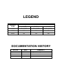
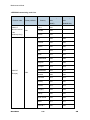
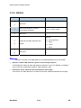
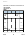
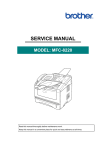
LEGEND
COMPANY
PRODUCT
CODE
LANIER
RICOH
SAVIN
M085
SP 1200SF
SP 1200SF
SP 1200SF
M086
NA
NA
NA
M104
NA
NA
NA
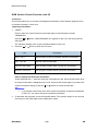
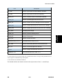
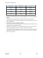
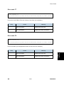
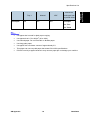
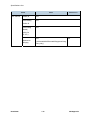
DOCUMENTATION HISTORY
REV. NO.
*
DATE
06/2011
COMMENTS
Original Printing
M085/M086
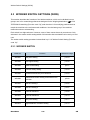
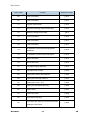
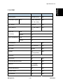
TABLE OF CONTENTS
PRODUCT INFORMATION
1. PRODUCT INFORMATION .......................................................... 1-1 1.1 SPECIFICATIONS ..................................................................................... 1-1 1.2 OVERVIEW................................................................................................ 1-2 1.2.1 PART NAMES .................................................................................. 1-2 Printer part ........................................................................................... 1-2 ADF / FB part ....................................................................................... 1-4 1.2.2 CROSS-SECTION DRAWING .......................................................... 1-6 Printer part ........................................................................................... 1-6 ADF part ............................................................................................... 1-7
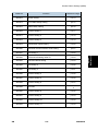
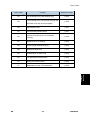
INSTALLATION
2. INSTALLATION ............................................................................ 2-1 2.1 INSTALLATION REQUIREMENTS............................................................ 2-1 2.1.1 OPERATING ENVIRONMENT ......................................................... 2-1 2.1.2 POWER SUPPLY ............................................................................. 2-1
PREVENTIVE MAINTENANCE
3. PREVENTIVE MAINTENANCE .................................................... 3-1 3.1 PERIODICAL REPLACEMENT PARTS .................................................... 3-1
REPLACEMENT AND ADJUSTMENT
4. REPLACEMENT AND ADJUSTMENT ........................................ 4-1 4.1 SAFETY PRECAUTIONS .......................................................................... 4-1 4.2 SCREW TORQUE LIST ............................................................................. 4-3 4.3 OVERVIEW OF GEARS ............................................................................ 4-7 4.4 HARNESS ROUTING ................................................................................ 4-9 4.4.1 ADF MOTOR, ADF SENSOR PCB ASSY TO MAIN PCB ASSY ..... 4-9 SM
i
M085/M086
4.4.2 NCU PCB, BATTERY ASSY, SPEAKER UNIT ASSY TO MAIN PCB
ASSY ....................................................................................................... 4-10 4.4.3 DOCUMENT SCANNER UNIT, PANEL PCB ASSY ....................... 4-11 4.4.4 FUSER UNIT .................................................................................. 4-12 4.4.5 FG HARNESS ................................................................................ 4-13 4.4.6 MAIN FRAME R ASSY ................................................................... 4-14 4.4.7 TONER LED PCB ASSY / LVPS PCB UNIT / MAIN PCB ASSY /
REGISTRATION FRONT SENSOR PCB ASSY / REGISTRATION REAR
SENSOR PCB ASSY ............................................................................... 4-15 4.4.8 TONER SENSOR PCB UNIT ASSY / NEW TONER SENSOR
HARNESS ASSY ..................................................................................... 4-16 4.4.9 HIGH-VOLTAGE PS PCB / REGISTRATION SOLENOID / T1
SOLENOID .............................................................................................. 4-17 4.5 DISASSEMBLE FLOW ............................................................................ 4-18 4.6 COMMON DISASSEMBLE PROCEDURE .............................................. 4-19 4.6.1 SEPARATION PAD ASSY .............................................................. 4-20 4.6.2 FRONT COVER ASSY ................................................................... 4-21 4.6.3 PAPER STOPPER L / PAPER STOPPER S .................................. 4-23 4.6.4 BACK COVER ................................................................................ 4-24 4.6.5 OUTER CHUTE ASSY ................................................................... 4-25 4.6.6 FUSER COVER ASSY ................................................................... 4-26 4.6.7 EJECT ACTUATOR / EJECT ACTUATOR SPRING ...................... 4-27 4.6.8 EJECT ROLLER ASSY 1 / BUSH C / BUSH R / BUSH L ............... 4-28 4.6.9 JOINT COVER SUB CHUTE ASSY................................................ 4-29 4.6.10 INNER CHUTE ASSY ................................................................. 4-30 4.6.11 FUSER UNIT .............................................................................. 4-31 4.6.12 CORNER COVER ...................................................................... 4-33 4.6.13 SIDE COVER L ASSY ................................................................ 4-34 4.6.14 SIDE COVER SUB L .................................................................. 4-35 4.6.15 MAIN SHIELD COVER PLATE ................................................... 4-36 4.7 ADF DISASSEMBLE PROCEDURE ........................................................ 4-37 4.7.1 ADF UNIT ....................................................................................... 4-37 4.7.2 HINGE R / HINGE ARM / HINGE ASSY L ...................................... 4-39 4.7.3 ADF COVER ASSY ........................................................................ 4-40 4.7.4 GEAR COVER ................................................................................ 4-41 4.7.5 DOCUMENT SEPARATOR ROLLER SHAFT ................................ 4-42 4.7.6 UPPER DOCUMENT CHUTE ASSY .............................................. 4-43 4.7.7 LOWER DOCUMENT CHUTE ASSY ............................................. 4-45 M085/M086
ii
SM
4.7.8 ADF SENSOR PCB ASSY.............................................................. 4-46 4.7.9 LF ROLLER ASSY .......................................................................... 4-48 4.7.10 EJECTION ROLLER ASSY ........................................................ 4-49 4.7.11 DRIVE FRAME ASSY ................................................................. 4-50 4.7.12 ADF MOTOR .............................................................................. 4-51 4.7.13 PRESSURE ROLLER ASSY ...................................................... 4-52 4.7.14 DOCUMENT STOPPER ............................................................. 4-53 4.7.15 DOCUMENT DRESS COVER .................................................... 4-54 4.8 SCANNER DISASSEMBLE PROCEDURE ............................................. 4-55 4.8.1 DOCUMENT SCANNER UNIT ....................................................... 4-55 4.8.2 CORD HOOK .................................................................................. 4-57 4.8.3 PANEL UNIT ................................................................................... 4-57 4.8.4 PANEL PCB ASSY ......................................................................... 4-58 4.8.5 RUBBER KEYS L/R ........................................................................ 4-59 4.8.6 LCD................................................................................................. 4-59 4.8.7 PANEL DRESS COVER ................................................................. 4-60 4.8.8 ADDRESS LABEL .......................................................................... 4-60 4.8.9 PULL ARM L/R ............................................................................... 4-61 4.8.10 PULL ARM GUIDE ..................................................................... 4-62 4.8.11 NCU PCB.................................................................................... 4-63 4.8.12 SPEAKER UNIT ......................................................................... 4-64 4.8.13 BATTERY ASSY......................................................................... 4-66 4.9 ENGINE DISASSEMBLE PROCEDURE ................................................. 4-67 4.9.1 SIDE COVER R ASSY.................................................................... 4-67 4.9.2 REGISTRATION GROUNDING SPRING ....................................... 4-68 4.9.3 ROLLER HOLDER ASSY ............................................................... 4-69 4.9.4 MAIN PCB ASSY ............................................................................ 4-71 4.9.5 JOINT COVER ASSY / PAPER SUPPORTER ............................... 4-72 4.9.6 EJECT ROLLER ASSY 2................................................................ 4-73 4.9.7 HIGH-VOLTAGE PS PCB ASSY .................................................... 4-74 4.9.8 NEW TONER SENSOR HARNESS ASSY ..................................... 4-75 4.9.9 FILTER ASSY ................................................................................. 4-76 4.9.10 LASER UNIT............................................................................... 4-77 4.9.11 FAN MOTOR 60 UNIT ................................................................ 4-79 4.9.12 COVER SENSOR HARNESS ASSY .......................................... 4-80 4.9.13 TONER LED PCB ASSY ............................................................ 4-81 4.9.14 LVPS PCB UNIT ......................................................................... 4-82 4.9.15 LV SHIELD PLATE 2 .................................................................. 4-84 SM
iii
M085/M086
REV. 11/30/2011
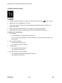
4.9.16 REGISTRATION FRONT SENSOR PCB ASSY......................... 4-85 4.9.17 REGISTRATION REAR SENSOR PCB ASSY ........................... 4-90 4.9.18 DRIVE SUB ASSY ...................................................................... 4-93 4.9.19 DEV JOINT / DEV GEAR JOINT 53R / REGISTRATION
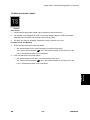
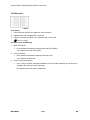
PENDULUM GEAR SPRING ................................................................... 4-95 4.9.20 THERMISTOR HARNESS UNIT ................................................ 4-96 4.9.21 TONER SENSOR PCB UNIT ASSY ........................................... 4-97 4.9.22 REGISTRATION SOLENOID ..................................................... 4-98 4.9.23 T1 SOLENOID .......................................................................... 4-100 4.9.24 MAIN SHIELD PLATE / EJECT SENSOR PCB ASSY ............. 4-101 4.9.25 RUBBER FOOT ........................................................................ 4-105 4.9.26 MAIN FRAME L ASSY .............................................................. 4-106 4.10 ADJUSTMENTS AND UPDATING OF SETTINGS, REQUIRED AFTER
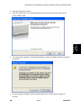
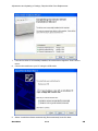
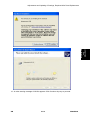
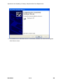
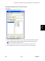
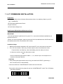
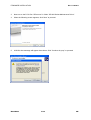
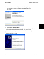
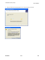
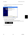
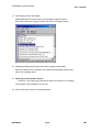
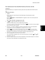
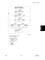
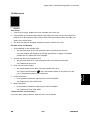
PARTS REPLACEMENT ............................................................................. 4-112 4.10.1 IF YOU REPLACE THE MAIN PCB .......................................... 4-112 Installing the maintenance printer driver........................................... 4-112 EEPROM parameter initialization of main PCB (Maintenance mode: code
01) .................................................................................................... 4-117 EEPROM customizing of main PCB (Maintenance mode: code 74) 4-117 Operational check of control panel button (Maintenance mode: code 13)4-117 Operational check of sensors (Maintenance mode: code 32) .......... 4-117 Acquisition of white level data and set the CIS scanner area
(Maintenance mode: code 55).......................................................... 4-117 Setting the serial number ................................................................. 4-117 Inputting the adjusted value of the laser scanner ............................. 4-119 4.10.2 IF YOU REPLACE THE LASER UNIT ...................................... 4-121 Inputting the adjustment value of the laser unit ................................ 4-121 4.10.3 IF YOU REPLACE THE FB UNIT ............................................. 4-124 Acquisition of white level data and set the CIS scanner area ........... 4-124 4.10.4 HOW TO SELECT THE PORT NUMBER................................. 4-125
4.11 FIRMWARE INSTALLATION .................................................... 4-127
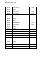
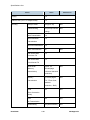
SERVICE MAINTENANCE
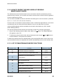
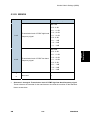
5. SERVICE MAINTENANCE ........................................................... 5-1 5.1 MAINTENANCE MODE ............................................................................. 5-1 5.1.1 HOW TO ENTER THE MAINTENANCE MODE ............................... 5-1 5.1.2 HOW TO ENTER THE END USER-ACCESSIBLE MAINTENANCE
MODE ........................................................................................................ 5-2 M085/M086
iv
SM
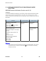
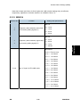
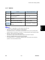
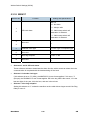
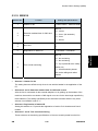
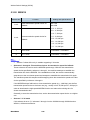
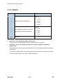
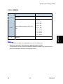
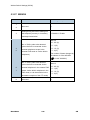
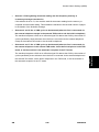
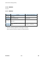
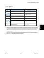
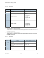
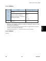
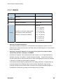
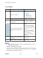
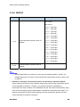
5.1.3 LIST OF MAINTENANCE-MODE FUNCTIONS ............................... 5-2 5.1.4 DETAILED DESCRIPTION OF MAINTENANCE-MODE FUNCTIONS5-4 EEPROM Parameter Initialization (Function code 01, 91).................... 5-4 Printout of Scanning Compensation Data (Function code 05).............. 5-5 Placement of CIS Unit in Position for Transportation (Function code 06)5-7 ADF Performance Test (Function code 08) .......................................... 5-8 Test Pattern (Function code 09) ........................................................... 5-9 Worker Switch Setting (Function code 10) ......................................... 5-10 Printout of Worker Switch Setting (Function code 11) ........................ 5-15 Operational Check of LCD (Function code 12)................................... 5-16 Operational Check of Control Panel Button (Function code 13) ......... 5-17 ROM Version Check (Function code 25) ............................................ 5-18 Operational Check of Sensors (Function code 32) ............................. 5-19 PC Print Function setting (Function code 43) ..................................... 5-22 Received Data Transfer Function (Function code 53) (M085 only) .... 5-32 Fine Adjustment of Scan Start/End Positions (Function code 54) ...... 5-35 Acquisition of White Level Data (Function code 55) ........................... 5-38 Paper Feeding and Ejecting Test (Function code 67) ........................ 5-38 EEPROM Customizing (Function code 74) ........................................ 5-39 Operational Check of Fans (Function code 78) .................................. 5-42 Display of the Machine's Log Information (Function code 80) ............ 5-43 Error Code Indication (Function code 82)........................................... 5-46 Output of Transmission Log to the Telephone Line (Function code 87)
(only M085) ........................................................................................ 5-46 Exit from the Maintenance Mode (Function code 99) ......................... 5-47 5.2 OTHER SERVICE FUNCTIONS .............................................................. 5-48 5.2.1 USER MAINTENANCE MODE ....................................................... 5-48 Resetting the drum counter ................................................................ 5-48 5.2.2 RESETTING THE DEVELOPING BIAS VOLTAGE COUNTER ..... 5-49 5.3 WORKER SWITCH SETTINGS (WSW) .................................................. 5-50 5.3.1 WORKER SWITCH......................................................................... 5-50 5.3.2 WSW01........................................................................................... 5-54 5.3.3 WSW02........................................................................................... 5-56 5.3.4 WSW03........................................................................................... 5-57 5.3.5 WSW04........................................................................................... 5-59 5.3.6 WSW05........................................................................................... 5-60 5.3.7 WSW06........................................................................................... 5-62 5.3.8 WSW07........................................................................................... 5-65 SM
v
M085/M086
5.3.9 WSW08........................................................................................... 5-67 5.3.10 WSW09 ...................................................................................... 5-68 5.3.11 WSW10 ...................................................................................... 5-70 5.3.12 WSW11 ...................................................................................... 5-71 5.3.13 WSW12 ...................................................................................... 5-72 5.3.14 WSW13 ...................................................................................... 5-74 5.3.15 WSW14 ...................................................................................... 5-75 5.3.16 WSW15 ...................................................................................... 5-76 5.3.17 WSW16 ...................................................................................... 5-77 5.3.18 WSW17 ...................................................................................... 5-78 5.3.19 WSW18 ...................................................................................... 5-79 5.3.20 WSW19 ...................................................................................... 5-80 5.3.21 WSW20 ...................................................................................... 5-81 5.3.22 WSW21 ...................................................................................... 5-82 5.3.23 WSW22 ...................................................................................... 5-83 5.3.24 WSW23 ...................................................................................... 5-84 5.3.25 WSW24 ...................................................................................... 5-86 5.3.26 WSW25 ...................................................................................... 5-87 5.3.27 WSW26 ...................................................................................... 5-88 5.3.28 WSW27 ...................................................................................... 5-90 5.3.29 WSW28 ...................................................................................... 5-91 5.3.30 WSW29 ...................................................................................... 5-92 5.3.31 WSW30 ...................................................................................... 5-92 5.3.32 WSW31 ...................................................................................... 5-93 5.3.33 WSW32 ...................................................................................... 5-94 5.3.34 WSW33 ...................................................................................... 5-94 5.3.35 WSW34 ...................................................................................... 5-95 5.3.36 WSW35 ...................................................................................... 5-95 5.3.37 WSW36 ...................................................................................... 5-96 5.3.38 WSW37 ...................................................................................... 5-97 5.3.39 WSW38 ...................................................................................... 5-98 5.3.40 WSW39 .................................................................................... 5-100 5.3.41 WSW40 .................................................................................... 5-101 5.3.42 WSW41 .................................................................................... 5-101 5.3.43 WSW42 .................................................................................... 5-101 5.3.44 WSW43 .................................................................................... 5-102 5.3.45 WSW44 .................................................................................... 5-102 5.3.46 WSW45 .................................................................................... 5-102 M085/M086
vi
SM
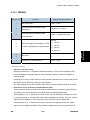
5.3.47 5.3.48 5.3.49 5.3.50 5.3.51 5.3.52 5.3.53 5.3.54 5.3.55 5.3.56 5.3.57 5.3.58 5.3.59 5.3.60 5.3.61 5.3.62 5.3.63 5.3.64 WSW46 .................................................................................... 5-102 WSW47 .................................................................................... 5-103 WSW48 .................................................................................... 5-103 WSW49 .................................................................................... 5-104 WSW50 .................................................................................... 5-104 WSW51 .................................................................................... 5-105 WSW52 .................................................................................... 5-105 WSW53 .................................................................................... 5-105 WSW54 .................................................................................... 5-106 WSW55 .................................................................................... 5-107 WSW56 .................................................................................... 5-108 WSW57 .................................................................................... 5-108 WSW58 .................................................................................... 5-108 WSW59 .................................................................................... 5-109 WSW60 .................................................................................... 5-109 WSW61 .................................................................................... 5-109 WSW62 .................................................................................... 5-109 WSW63 .................................................................................... 5-109
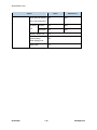
TROUBLESHOOTING
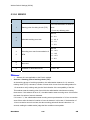
6. TROUBLESHOOTING ................................................................. 6-1 6.1 INTRODUCTION ....................................................................................... 6-1 6.1.1 PRECAUTIONS ................................................................................ 6-1 6.1.2 INITIAL CHECK ................................................................................ 6-2 6.2 ERROR CAUSE......................................................................................... 6-3 6.2.1 ERROR INDICATION ....................................................................... 6-3 6.2.2 RECOVERABLE USER CHECK ERRORS ...................................... 6-6 Error code 67 ....................................................................................... 6-6 Error code 75 ....................................................................................... 6-6 6.2.3 SERVICE CALL ERRORS ................................................................ 6-7 Error code 50 ....................................................................................... 6-7 Error code 56 ....................................................................................... 6-8 Error code 58/ 59 ................................................................................. 6-9 Error code 5A ..................................................................................... 6-10 Error code 5B ..................................................................................... 6-11 Error code 63 ..................................................................................... 6-12 Error code 68/ 69/ 6A/ 6B/ 6C/ 6D/ 6E/ 6F ......................................... 6-13 SM
vii
M085/M086
Error code 71/ 72 ............................................................................... 6-15 Error code 76 ..................................................................................... 6-16 Error code 77 ..................................................................................... 6-17 Error code 78 ..................................................................................... 6-17 Error code 79 ..................................................................................... 6-18 Error code 7A ..................................................................................... 6-18 Error code 7B ..................................................................................... 6-19 Error code 7D ..................................................................................... 6-19 Error code 7F ..................................................................................... 6-19 Error code 80 ..................................................................................... 6-20 Electrodes location on the drum unit .................................................. 6-21 Electrodes location on the machine ................................................... 6-21 Error code 84 (Jam Rear)/ 88 (Jam Inside) ........................................ 6-22 Error code 8A ..................................................................................... 6-25 Error code 8D ..................................................................................... 6-26 Error code 9F ..................................................................................... 6-27 Error code A1 ..................................................................................... 6-28 Error code A2 ..................................................................................... 6-29 Error code A3 ..................................................................................... 6-29 Error code A5 ..................................................................................... 6-30 Error code A6 ..................................................................................... 6-30 Error code AD .................................................................................... 6-31 Error code AF ..................................................................................... 6-31 Error code B0 ..................................................................................... 6-32 Error code B7 ..................................................................................... 6-32 Error code B9 ..................................................................................... 6-33 Error code BB ..................................................................................... 6-33 Error code E6 ..................................................................................... 6-34 Error code EC .................................................................................... 6-34 Error code F8 ..................................................................................... 6-35 Error code F9 ..................................................................................... 6-35 6.3 PAPER FEEDING PROBLEMS ............................................................... 6-36 6.3.1 NO FEEDING ................................................................................. 6-36 6.3.2 DOUBLE FEEDING ........................................................................ 6-37 6.3.3 PAPER JAM ................................................................................... 6-37 Paper jam in the paper tray and front cover ....................................... 6-37 Paper jam in the back cover and paper eject section ......................... 6-38 Dirt on paper ...................................................................................... 6-38 M085/M086
viii
SM
Wrinkles or creases ............................................................................ 6-39 Waves in the paper / folds in the paper at the eject roller 2................ 6-39 Curl in the paper ................................................................................. 6-40 6.4 TROUBLESHOOTING OF DOCUMENT FEEDING ................................ 6-41 6.4.1 NO FEEDING ................................................................................. 6-41 6.4.2 DOUBLE FEEDING ........................................................................ 6-42 6.4.3 PAPER JAM ................................................................................... 6-42 6.5 IMAGE DEFECT TROUBLESHOOTING (DEFECT OF THE PRINT) ...... 6-44 6.5.1 IMAGE DEFECT EXAMPLES ......................................................... 6-44 6.5.2 DIAMETER OF ROLLERS .............................................................. 6-45 6.5.3 TROUBLESHOOTING IMAGE DEFECT ........................................ 6-46 1 Light ................................................................................................ 6-46 2 Faulty registration ............................................................................ 6-48 3 Dark................................................................................................. 6-48 4 Poor fixing ....................................................................................... 6-49 5 Completely blank ............................................................................. 6-50 6 Image distortion ............................................................................... 6-51 7 All black ........................................................................................... 6-51 8 Dirt on the back of paper ................................................................. 6-53 9 Vertical streaks ................................................................................ 6-53 10 Black vertical streaks in a light background................................... 6-54 11 Black horizontal stripes ................................................................. 6-54 12 White vertical streaks .................................................................... 6-56 13 White horizontal streaks ................................................................ 6-57 14 Faint print ...................................................................................... 6-58 15 White spots ................................................................................... 6-59 16 Black spots .................................................................................... 6-60 17 Black band .................................................................................... 6-62 18 Downward fogging of solid color ................................................... 6-62 19 Horizontal lines .............................................................................. 6-63 20 Ghost............................................................................................. 6-64 21 Fogging ......................................................................................... 6-65 6.6 TROUBLESHOOTING OF SCANNING ................................................... 6-66 6.6.1 CANNOT SCAN THE DOCUMENT IN THE FB UNIT. (IF SCAN THE
DOCUMENT, IT IS COMPLETELY WHITE OR BLACK.) ........................ 6-66 6.6.2 CANNOT SCAN THE DOCUMENT IN THE ADF UNIT. (IF SCAN THE
DOCUMENT, IT IS COMPLETELY WHITE OR BLACK.) ........................ 6-66 6.6.3 PRINT OF THE SCANNING DOCUMENT IS LIGHT OR DARK .... 6-67 SM
ix
M085/M086
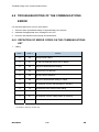
6.6.4 VERTICAL STREAKS (WHITE OR BLACK VERTICAL STREAKS)6-67 6.6.5 POOR FIXING ................................................................................ 6-68 6.6.6 IMAGE DISTORTION ..................................................................... 6-68 6.7 SOFTWARE SETTING PROBLEMS ....................................................... 6-69 6.8 TROUBLESHOOTING OF THE COMMUNICATIONS ERROR............... 6-70 6.8.1 DEFINITION OF ERROR CODES ON THE COMMUNICATIONS LIST6-70 6.9 TROUBLESHOOTING OF THE CONTROL PANEL ................................ 6-79 6.9.1 NOTHING IS DISPLAYED ON THE LCD. ...................................... 6-79 6.9.2 THE CONTROL PANEL DOES NOT WORK. ................................. 6-80 6.10 TROUBLESHOOTING OF FAX FUNCTIONS ................................... 6-81 6.10.1 FAX CAN'T BE SENT. ................................................................ 6-81 6.10.2 SPEED DIALING AND ONE-TOUCH DIALING CAN'T BE USED.6-82 6.10.3 FAX CAN NOT BE RECEIVED................................................... 6-83 6.10.4 NO RINGING SOUND. ............................................................... 6-83 6.10.5 SPEAKER IS SILENT DURING ON-HOOK DIALING. ............... 6-84 6.10.6 DIALING FUNCTION DOES NOT SWITCH BETWEEN "TONE"
AND "PULSE". ......................................................................................... 6-85 6.11 OTHERS PROBLEMS ....................................................................... 6-86 6.11.1 THE MACHINE IS NOT TURNED ON, OR THE LCD INDICATION
DOES NOT APPEAR. .............................................................................. 6-86 6.11.2 THE FAN DOES NOT WORK..................................................... 6-86 6.11.3 PICKUP FUNCTION OF PAPER TRAY DOES NOT WORK...... 6-87 6.11.4 A NEW TONER CANNOT BE DETECTED. ............................... 6-87
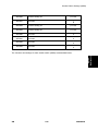
ENERGY SAVING
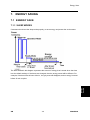
7. ENERGY SAVING ........................................................................ 7-1 7.1 ENERGY SAVE ......................................................................................... 7-1 7.1.1 SLEEP MODES ................................................................................ 7-1 Timer Settings ...................................................................................... 7-2 Return to Stand-by Mode ..................................................................... 7-2 Recommendation ................................................................................. 7-2 7.2 PAPER SAVE ............................................................................................ 7-3 7.2.1 EFFECTIVENESS OF COMBINE FUNCTION ................................. 7-3 1. Combine mode: ................................................................................ 7-3 tal counters........................................................................................... 7-4 M085/M086
x
SM
M085/M086/M104 SERVICE MANUAL APPENDICES
SEE M085/M086/M104 SERVICE MANUAL APPENDICES SECTION FOR DETAILED TABLE
OF CONTENTS
SM
xi
M085/M086
SERVICE MAINTENANCE
TROUBLESHOOTING
ENERGY SAVING
TAB
POSITION 1
TAB
POSITION 2
TAB
POSITION 3
TAB
POSITION 4
REPLACEMENT AND ADJUSTMENT
TAB
POSITION 5
PREVENTIVE MAINTENANCE
TAB
POSITION 6
INSTALLATION
TAB
POSITION 7
APPENDIX: SPECIFICATIONS
TAB
POSITION 8
PRODUCT INFORMATION
READ THIS FIRST
Regulations
<For Europe and Other countries>
Radio interference (220 to 240 volt model only)
This machine follows EN55022 (CISPR Publication 22)/Class B.
IEC 60825-1 specification (220 to 240 volt model only)
This machine is a Class 1 laser product as defined in IEC 60825-1 specifications.
The
label shown below is attached in countries where it is needed.
This machine has a Class 3B laser diode which produces invisible laser radiation in the
laser unit. You should not open the laser unit under any circumstances.
Caution
Use of controls or adjustments or performance of procedures other than those specified in
this manual may result in hazardous radiation exposure.
For Finland and Sweden
LUOKAN 1 LASERLAITE
KLASS 1 LASER APPARAT
Varoitus!
Laitteen käyttäminen muulla kuin tässä käyttöohjeessa mainitulla tavalla saattaa altistaa
käyttäjän turvallisuusluokan 1 ylittävälle näkymättömälle lasersäteilylle.
Varning
Om apparaten används på annat sätt än i denna Bruksanvisning specificerats, kan
användaren utsättas för osynlig laserstrålning, som överskrider gränsen för laserklass 1.
Internal laser radiation
Maximum radiation power: 10 mW
Wave length: 780 - 800 nm
Laser class: Class 3B
EU Directive 2002/96/EC and EN50419
(European Union only)
This equipment is marked with the recycling symbol below.
It means that at the end of the
life of the equipment you must dispose of it separately at an appropriate collection point and
not place it in the normal domestic unsorted waste stream.
This will benefit the
environment for all. (European Union only)
<For USA and Canada>
Federal Communications Commission (FCC) Declaration of Conformity
(For USA)
Responsible Party:
Ricoh Americas Corporation
5 Dedrick Place, West Caldwell, NJ 07006 USA
Telephone: 973-882-2000
declares, that the products
Product name: Laser Multi Function
Model number: SP 1200SF
complies with Part 15 of the FCC Rules. Operation is subject to the following two
conditions: (1) This device may not cause harmful interference, and (2) this device must
accept any interference received, including interference that may cause undesired
operation.
This equipment has been tested and found to comply with the limits for a Class B digital
device, pursuant to Part 15 of the FCC Rules.
These limits are designed to provide
reasonable protection against harmful interference in a residential installation.
This
equipment generates, uses, and can radiate radio frequency energy and, if not installed
and used in accordance with the instructions, may cause harmful interference to radio
communications.
However, there is no guarantee that interference will not occur in a
particular installation.
If this equipment does cause harmful interference to radio or
television reception, which can be determined by turning the equipment off and on, the end
user is encouraged to try to correct the interference by one or more of the following
measures:
Reorient or relocate the receiving antenna.
Increase the separation between the equipment and receiver.
Connect the equipment into an outlet on a circuit different from that to which the
receiver is connected.
Consult the dealer or an experienced radio/TV technician for help.
A shielded interface cable should be used to ensure compliance with the limits for
a Class B digital device. Changes or modifications not expressly approved by the
party responsible for compliance could void the user’s authority to operate the
equipment.
Industry Canada Compliance Statement (For Canada)
This Class B digital apparatus complies with Canadian ICES-003.
Cet appareil numérique de la classe B est conforme à la norme NMB-003 du Canada.
Laser Safety (110 to 120 volt model only)
This machine is certified as a Class 1 laser product under the U.S. Department of Health
and Human Services (DHHS) Radiation Performance Standard according to the Radiation
Control for Health and Safety Act of 1968.
This means that the machine does not produce
hazardous laser radiation.
Since radiation emitted inside the machine is completely confined within protective
housings and external covers, the laser beam cannot escape from the machine during any
phase of user operation.
FDA Regulations (110 to 120 volt model only)
The U.S. Food and Drug Administration (FDA) has implemented regulations for laser
products manufactured on and after August 2, 1976.
products marketed in the United States.
Compliance is mandatory for
The following label on the back of the machine
indicates compliance with the FDA regulations and must be attached to laser products
marketed in the United States.
MANUFACTURED:
RICOH COMPANY LTD, 3-6, Naka-magome 1-Chome Ohta-ku, Tokyo 143-8555,
Japan
Complies with FDA performance standards for laser products except for deviations
pursuant to Laser Notice No. 50, dated June 24, 2007.
Internal laser radiation
Maximum radiation power: 10 mW
Wave length: 780 - 800 nm
Laser class: Class 3B
Safety Information
Caution for Laser Product (WARNHINWEIS fur Laser drucker)
CAUTION:
When servicing the machine and it is operated with the cover open, the regulations of VBG
93 and the performance instructions for VBG 93 are valid.
CAUTION:
In case of any trouble with the laser unit, replace the laser unit itself. To prevent direct
exposure to the laser beam, do not try to open the enclosure of the laser unit.
ACHTUNG:
Im Falle von Störungen der Lasereinheit muß diese ersetzt werden. Das Gehäuse der
Lasereinheit darf nicht geöffnet werden, da sonst Laserstrahlen austreten können.
Additional Information
When servicing the optical system of the machine, be careful not to place a screwdriver or
other reflective object in the path of the laser beam.
Be sure to take off any personal
accessories such as watches and rings before working on the machine.
A reflected beam,
though invisible, can permanently damage the eyes.
Since the beam is invisible, the following caution label is attached on the laser unit.
Definitions of Warnings, Cautions, and Notes
The following conventions are used in this manual:
Warnings tell you what to do to prevent possible personal injury.
Cautions specify procedures you must follow or avoid to prevent possible damage to the
machine or other objects.
Notes tell you useful tips when servicing the machine and bits of knowledge to help
understand the machine.
Mark
Contents
Electrical Hazard icons alert you to a possible electrical shock.
Hot Surface icons warn you not to touch machine parts that are hot.
Safety Precautions
Please keep these instructions for later reference and read them before attempting any
maintenance.
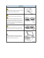
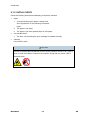
WARNING
There are high voltage electrodes inside the
machine. Before you clean the inside of the
machine, make sure you have unplugged the
telephone line cord first and then the power cord
from the AC power outlet. (Refer to the User’s
Guide.)
DO NOT use flammable substances such as
alcohol, benzine, thinner or any type of spray to
clean the inside or outside of the machine. Doing
this may cause a fire or electrical shock. Refer to
the User’s Guide for how to clean the machine.
WARNING
DO NOT handle the plug with wet hands. Doing
this might cause an electrical shock.
Always make sure the plug is fully inserted.
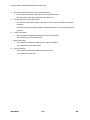
After you have just used the machine, some
internal parts of the machine will be extremely
hot. When you open the front or back cover of
the machine, DO NOT touch the shaded parts
shown in the illustration.
The fuser unit is marked with a caution label.
Please DO NOT remove or damage the label.
To prevent injuries, be careful not to put your
hands on the edge of the machine under the
document cover or scanner cover.
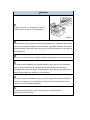
WARNING
To prevent injuries, be careful not to put your
fingers in the area shown in the illustration.
DO NOT use a vacuum cleaner to clean up scattered toner. Doing this might cause
the toner dust to ignite inside the vacuum cleaner, potentially starting a fire. Please
carefully clean the toner dust with a dry, lint-free cloth and dispose of it according to
local regulations.
When you move the machine, grasp the side hand holds that are under the scanner.
Use caution when installing or modifying telephone lines. Never touch telephone
wires or terminals that are not insulated unless the telephone line has been
unplugged at the wall jack. Never install telephone wiring during a lightning storm.
Never install a telephone wall jack in a wet location.
This product must be installed near an AC power outlet that is easily accessible. In
case of an emergency, you must disconnect the power cord from the AC power
outlet to shut off the power completely.
To reduce the risk of shock or fire, use only a No. 26 AWG or larger
telecommunication line cord.
CAUTION
Lightning and power surges can damage this product! We recommend that you use
a quality surge protection device on the AC power line and on the telephone line, or
unplug the cords during a lightning storm.
WARNING
IMPORTANT SAFETY INSTRUCTIONS
When using your telephone equipment, basic safety precautions should always be
followed to reduce the risk of fire, electric shock and injury to people, including the
following:
1.
DO NOT use this product near water, for example, near a bath tub, wash bowl,
kitchen sink, washing machine, or in a wet basement or near a swimming pool.
2.
Avoid using this product during an electrical storm. There may be a remote risk
of electric shock from lightning.
3.
DO NOT use this product to report a gas leak in the vicinity of the leak.
4.
Use only the power cord provided with the machine.
5.
DO NOT dispose of batteries in a fire. They may explode. Check with local
codes for possible special disposal instructions.
SAVE THESE INSTRUCTIONS
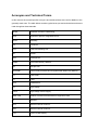
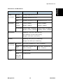
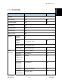
Acronyms and Technical Terms
In this manual, the manual specific acronyms and technical terms are used in addition to the
generally used ones. The table below contains typical acronyms and technical terms that are
used throughout these manuals.
APIPA
Automatic Private IP Addressing
ASIC
Application Specific Integrated Circuit
ASSY
Assembly
CN
Connector
CPU
Central Processing Unit
dB
decibel
DEV
Development
DIMM
Dual Inline Memory Module
dpi
dots per inch
EEPROM
Electronically Erasable and Programmable Read Only Memory
FR
Feed Roller
FU
Fuser
HEX
Hexadecimal
HV
High Voltage
HVPS
High Voltage Power Supply
IEEE 1284
Institute of Electrical and Electronic Engineers 1284
IF
Interface
IPv4
Internet Protocol Version 4
IPv6
Internet Protocol Version 6
LCD
Liquid Crystal Display
LD
Laser Diode
LED
Light Emitting Diode
LV
Low Voltage
LVPS
Low Voltage Power Supply
N/A
Not Applicable
NC*
Network Circuit
NVRAM
Nonvolatile Random Access Memory
PF
Paper Feed
PP gear
Pressure Plate gear
ppm
pages per minute
PU
Pick-Up roller
RAM
Random Access Memory
REGI
Registration
SOL
Solenoid
SP
Spare Parts
TE
Toner Empty
TN
Toner
TR
Transfer
* Excluding the acronym shown on the wiring diagram or circuit diagram.
PRODUCT INFORMATION
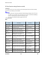
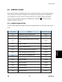
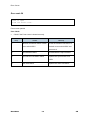
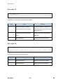
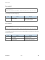
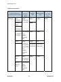
R E V I S I O N H I S T O RY
P a ge
Date
A d de d /U pd at e d /N ew
None
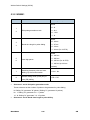
Specifications
Product
Information
1. PRODUCT INFORMATION
1.1 SPECIFICATIONS
See "Appendices" for the following information:
SM
Specifications List
1-1
M085/M086
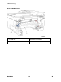
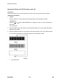
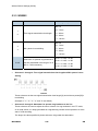
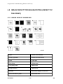
Overview
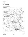
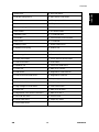
1.2 OVERVIEW
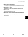
1.2.1 PART NAMES
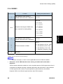
Printer part
M085/M086
1-2
SM
Overview
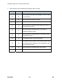
28. Drive sub ASSY
2. Pull arm spring ADF R
29. Eject sensor PCB ASSY
3. Pull arm R
30. DEV gear joint/53R
4. Pull arm L
31. DEV joint
5. Pull arm spring ADF
32. New toner sensor harness ASSY
6. NCU shield
33. PT sensor holder
7. Speaker cover
34. T1 solenoid lever
8. Lock claw
35. Toner sensor PCB unit ASSY
9. NCU PCB
36. T1 solenoid
10. Battery ASSY
37. Roller holder ASSY
11. Speaker hold spring
38. Rubber foot
12. Fuser cover
39. Registration front sensor PCB ASSY
13. Pull arm guide
40. Fan motor 60 unit
14. Outer chute ASSY
41. Cover sensor harness ASSY
15. Joint cover ASSY
42. LED holder
16. Speaker unit
43. Toner LED PCB ASSY
17. Fuser unit
44. Side cover L ASSY
18. Filter ASSY
45. Registration solenoid lever
19. Joint cover sub chute ASSY
46. Registration solenoid
20. Eject roller ASSY 2
47. Paper stopper L
21. Main PCB ASSY
48. Paper stopper S
22. High-voltage PS PCB ASSY
49. Front cover ASSY
23. Laser unit
50. Side cover R ASSY
24. Registration rear sensor PCB ASSY
51. Side cover sub L
25. PS PCB unit ASSY
52. Corner cover
26. Pinch roller ASSY
53. Paper tray ASSY
Product
Information
1. Back cover
27. Inner chute ASSY
SM
1-3
M085/M086
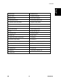
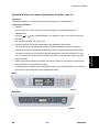
Overview
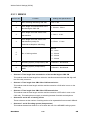
ADF / FB part
M085/M086
1-4
SM
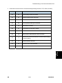
1. Gear cover
20. Rubber key R
2. ADF cover
21. Panel PCB ASSY
3. Address label
22. Document stopper
4. Panel dress cover
23. Document dress cover
5. Separate roller shaft ASSY
24. Ejection roller ASSY
6. Separate roller bushing
25. LF roller ASSY
7. Separation rubber
26. LF roller bushing
8. ADF plate spring
27. Drive frame ASSY
9. LCD
28. ADF harness unit
10. Diffusion film
29. harness holder
11. Panel unit
30. ADF motor
12. Upper document chute ASSY
31. Actuator L
13. Pressure roller ASSY
32. Actuator R
14. Pressure roller spring
33. Lower document chute ASSY
15. Hinge ASSY L
34. ADF sensor PCB ASSY
16. Back light guide
35. Document cover sub ASSY
17. Rubber key L
36. Cord hook
18. Hinge R
37. Document scanner unit
Product
Information
Overview
19. Hinge arm
SM
1-5
M085/M086
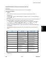
Overview
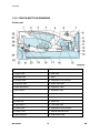
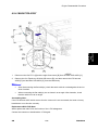
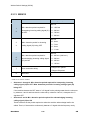
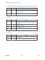
1.2.2 CROSS-SECTION DRAWING
Printer part
1. Laser unit
15. Pressure roller
2. Supply roller
16. Heat roller
3. Develop roller
17. Plate
4. Transfer roller
18. Registration rear actuator
5. Exposure drum
19. Paper feed roller
6. Paper stack lever
20. Separation roller
7. Eject roller 2
21. Separation pad
8. Pinch roller
22. Separation pad ASSY
9. Back cover
23. Edge actuator
10. Fuser unit
24. Paper tray
11. Eject roller 1
25. Front feed roller
12. Outer chute
26. Registration front actuator
13. Fuser cover
27. Manual feed slot cover
14. Eject actuator
28. Registration roller
M085/M086
1-6
SM
Product
Information
Overview
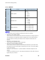
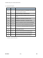
ADF part
1. LF roller
6. Document cover
2. Pressure roller
7. Pressure roller
3. Separation roller shaft ASSY
8. Document front actuator
4. ADF motor
9. Document rear actuator
5. Ejection roller
10. Pressure roller
SM
1-7
M085/M086
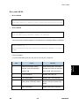
INSTALLATION
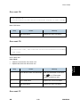
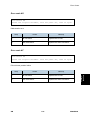
R E V I S I O N H I S T O RY
P a ge
Date
A d de d /U pd at e d /N ew
None
Installation Requirements
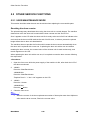
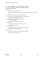
2. INSTALLATION
2.1.1 OPERATING ENVIRONMENT
1.
Put your machine on a flat, stable surface such as a desk that is free of vibration and
shocks.
2.
Use the machine in a well-ventilated room; use the machine within the following ranges of
temperature and humidity: temperature between 10°C and 32.5°C (50°F to 90.5°F), and
the relative humidity is maintained between 20% and 80%.
3.
The machine is not exposed to direct sunlight, excessive heat, moisture, or dust.
4.
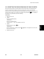
Condensation
When the machine is moved from a cold place into a warm room, condensation may occur
inside the machine, causing various problems as listed below.
Condensation on the optical surfaces such as the scanner window, lenses, the
reflection mirror and the protection glass may cause the print image to be light.
If the exposure drum is cold, the electrical resistance of the photosensitive layer is
increased, making it impossible to obtain the correct contrast when printing.
Condensation on the charge unit may cause corona charge leakage.
Condensation on the plate and separation pad may cause paper feed failures.
If condensation has occurred, leave the machine for at least 2 hours to allow it to reach
room temperature.
If the drum unit is unpacked soon after it is moved from a cold place to a warm room,
condensation may occur inside the unit which may cause incorrect images. Instruct the end
user to allow the unit to come to room temperature before unpacking it. This will take one or
two hours.
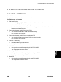
2.1.2 POWER SUPPLY
1.
The AC input power supply described on the rating plate of the machine should be within
±10% of the rated voltage.
2.
The AC input power supply is within the regulated value.
3.
The cables and harnesses are connected correctly.
4.
The fuses are not blown.
SM
2-1
M085/M086
Installation
2.1 INSTALLATION REQUIREMENTS
PREVENTIVE MAINTENANCE
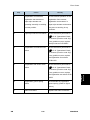
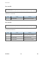
R E V I S I O N H I S T O RY
P a ge
Date
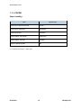
A d de d /U pd at e d /N ew
None
Periodical Replacement Parts
3. PREVENTIVE MAINTENANCE
3.1 PERIODICAL REPLACEMENT PARTS
Preventive
Maintenance
There are no parts to be replaced periodically.
SM
3-1
M085/M086
REPLACEMENT AND ADJUSTMENT
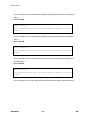
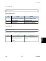
R E V I S I O N H I S T O RY
P a ge
Date
127 ~ 132
11/30/2011
A d de d /U pd at e d /N ew
Firmware Installation
Safety Precautions
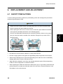
4. REPLACEMENT AND ADJUSTMENT
4.1 SAFETY PRECAUTIONS
To avoid creating secondary problems by mishandling, follow the warnings and precautions
below during maintenance work.
WARNING
Always turn off the power switch and unplug the power cord from the power outlet
before accessing any parts inside the machine.
When opening the front cover or back cover to access any parts inside the machine,
never touch the shaded parts shown in the following figures.
DO NOT use flammable substances such as alcohol, benzine, thinner or any type of
spray to clean the inside or outside of the machine. Doing this may cause a fire or
electrical shock.
Be careful not to lose screws, washers, or other parts removed.
Be sure to apply grease to the gears and applicable positions specified in this chapter.
When using soldering irons or other heat-generating tools, take care not to accidentally
damage parts such as wires, PCBs and covers.
Static electricity charged in your body may damage electronic parts, When transporting
PCBs, be sure to wrap them in conductive sheets.
When replacing the PCB and all the other related parts, put on a grounding wrist band and
perform the job on a static mat. Also take care not to touch the conductor sections on the
flat cables or on the wire harness.
SM
4-1
M085/M086
Replacement
and
Adjustment
Safety Precautions
When connecting or disconnecting cable connectors, hold the connector body, not the
cables. If the connector has a lock, release the connector lock first to release it.
After a repair, check not only the repaired portion but also all connectors. Also check that
other related portions are functioning properly before operational checks.
After disconnecting flat cables, check that each cable is not damaged at its end or
short-circuited.
When connecting flat cables, do not insert them at an angle. After insertion, check that the
cables are not at an angle.
M085/M086
4-2
SM
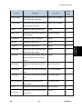
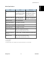
Screw Torque List
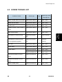
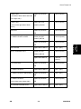
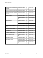
4.2 SCREW TORQUE LIST
Location of screw
Screw type
Q’ty
Tightening torque
Nm (kgf·cm)
JOINT COVER SUB CHUTE ASSY Taptite bind B M4x12
2
0.8±0.1 (8±1)
INNER CHUTE ASSY
Taptite bind B M4x12
2
0.6±0.1 (6±1)
FUSER UNIT
Taptite pan B M4x14
2
0.8±0.1 (8±1)
CONER COVER / SIDE COVER L
Taptite bind B M4x12
3
0.8±0.1 (8±1)
SIDE COVER SUB L
Taptite bind B M4x12
1
0.8±0.1 (8±1)
MAIN SHIELD COVER PLATE
Taptite cup S M3x6
1
0.9±0.05 (9±0.5)
2
0.55±0.05
SR
MAIN SHIELD COVER PLATE
Taptite cup S M3x6
(FG are tightened together)
SR
ADF UNIT
Taptite bind B M4x12
1
0.8±0.1 (8±1)
HINGE ARM
Taptite bind B M4x12
1
0.8±0.1 (8±1)
HINGE ASSY L
Taptite cup S M3x12
1
0.8±0.1 (8±1)
Taptite cup B M3x10
2
0.5±0.1 (5±1)
Taptite cup B M3x10
4
0.5±0.1 (5±1)
Taptite cup B M3x10
2
0.5±0.1 (5±1)
Taptite cup B M3x10
2
0.5±0.1 (5±1)
UPPER DOCUMENT CHUTE
(5.5±0.5)
ASSY
LOWER DOCUMENT CHUTE
ASSY
DRIVE FRAME ASSY
SM
4-3
M085/M086
Replacement
and
Adjustment
ASSY
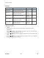
Screw Torque List
ADF harness unit (FG)
Taptite cup S M3x6
1
0.8±0.1 (8±1)
SR
ADF MOTOR
Taptite bind B M3x6
1
0.8±0.1 (8±1)
DOCUMENT DRESS COVER
Taptite cup B M3x8
1
0.5±0.1 (5±1)
CORD HOOK
Taptite cup B M3x8
2
0.5±0.1 (5±1)
PANEL UNIT
Taptite cup B M3x10
4
0.5±0.1 (5±1)
PRINTED PANEL COVER
Taptite cup B M3x8
4
0.4±0.1 (4±1)
NCU SHIELD
Taptite bind B M4x12
2
0.8±0.1 (8±1)
Screw pan (S/P
1
0.5±0.05 (5±0.5)
2
0.5±0.1 (5±1)
washer) M3.5x6
NCU PCB
Taptite cup S M3x6
SR
SPEARKER COVER
Taptite bind B M4x12
1
0.8±0.1 (8±1)
SIDE COVER R ASSY
Taptite bind B M4x12
2
0.8±0.1 (8±1)
MAIN PCB ASSY
Taptite cup S M3x6
4
0.6±0.1 (6±1)
SR
JOINT COVER ASSY
Taptite bind B M4x12
5
0.8±0.1 (8±1)
HIGH-VOLTAGE PS PCB ASSY
Taptite cup S M3x6
2
0.8±0.05 (8±0.5)
2
0.8±0.05 (8±0.5)
SR
Taptite bind B M4x12
M085/M086
4-4
SM
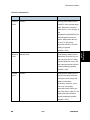
Screw Torque List
LASER UNIT
(Left side of Main frame and back
Taptite cup S M3x6
3
0.8±0.05 (8±0.5)
1
0.8±0.05 (8±0.5)
2
0.8±0.05 (8±0.5)
1
0.5±0.05 (5±0.5)
2
0.5±0.05 (5±0.5)
SR
of the right side.)
LASER UNIT
(Front of the right side of Main
Taptite pan (S/P
washer) S M3x8
frame.)
AIR DUCT
Taptite cup S M3x6
SR
LV SHIELD PLATE COVER
Screw pan (S/P
Taptite cup S M3x6
SR
SW HOLDER
Taptite bind B M4x12
1
0.8±0.1 (8±1)
INLET HARNESS ASSY
Screw pan (S/P
1
0.5±0.05 (5±0.5)
2
0.45±0.05
washer) M3.5x6
Taptite flat B M3x10
(4.5±0.5)
LVPS PCB UNIT
Taptite cup S M3x6
2
0.5±0.05 (5±0.5)
SR
LV SHIELD PLATE 2
Taptite bind B M4x12
2
0.8±0.1 (8±1)
LV SHIELD PLATE 2 (Back Side)
Taptite cup S M3x6
1
0.6±0.1 (6±1)
1
0.5±0.05 (5±0.5)
2
0.5±0.1 (5±1)
SR
LV SHIELD PLATE 2
Taptite cup S M3x6
(Front chute ground plate side)
SR
ACTUATOR HOLDER ASSY
Taptite bind B M3x10
SM
4-5
M085/M086
Replacement
and
Adjustment
washer) M3.5x6
Screw Torque List
REGISTRATION FRONT SENSOR Taptite bind B M3x10
1
0.5±0.1 (5±1)
REAR ACTUATOR HOLDER ASSY Taptite bind B M3x10
2
0.5±0.1 (5±1)
REGISTRATION REAR SENSOR
Taptite bind B M3x10
1
0.5±0.1 (5±1)
Taptite bind B M4x12
1
0.8±0.1 (8±1)
Taptite cup S M3x6
1
0.8±0.05 (8±0.5)
1
0.6±0.1 (6±1)
Taptite bind B M4x12
9
0.8±0.1 (8±1)
Taptite bind B M3x10
1
0.5±0.1 (5±1)
REGISTRATION SOLENOID
Taptite bind B M3x10
1
0.5±0.1 (5±1)
T1 SOLENOID
Taptite bind B M3x10
1
0.5±0.1 (5±1)
FU FRONT PAPER GUIDE
Taptite bind B M3x10
3
0.5±0.1 (5±1)
CHUTE GROUND PLATE
Taptite cup S M3x6
2
0.6±0.1 (6±1)
PCB ASSY
PCB ASSY
UNDER FG WIRE
SR
DRIVE SUB ASSY
Taptite cup S M3x6
SR
TONER SENSOR HARNESS
ASSY
SR
MAIN SHIELD PLATE
Taptite bind B M4x12
3
0.8±0.1 (8±1)
MAIN FRAME L ASSY
Taptite bind B M4x12
4
0.8±0.1 (8±1)
Taptite cup S M3x6
2
0.7±0.1 (7±1)
SR
M085/M086
4-6
SM
Overview of Gears
Replacement
and
Adjustment
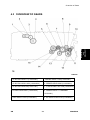
4.3 OVERVIEW OF GEARS
1. EJECTOR GEAR 17 (LU2016001)
9. FEEDER GEAR 17/22 (LU2043001)
2. EJECTOR GEAR 15/25 (LU2018001)
10. FEEDER GEAR 26/20 (LU2042001)
3. EJECTOR GEAR 26 (LU2017001)
11. T1 GEAR 38/31 SECTOR (LU2044001)
4. FUSER GEAR 22/37 (LU2015001)
12. FEEDER GEAR 17 TERMINAL
(LU2129001)
5. DEV GEAR 17/33L (LU2054001)
SM
13. P/P GEAR 29 SECTOR (LU2045001)
4-7
M085/M086
Overview of Gears
6. REGISTRATION GEAR 27 PENDULUM
14. REGISTRATION GEAR 19
(LU2048001)
(LU2047001)
7. REGISTRATION DIFFERENTIAL GEAR 15. DEV GEAR 17/18R/47R (LU2053001)
ASSY (LU2049001)
8. REGISTRATION GEAR 25 TERMINAL
16. ( ) is part code.
(LU2128001)
The part codes of gears are subject to change without notice.
M085/M086
4-8
SM
Harness Routing
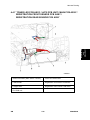
4.4 HARNESS ROUTING
Replacement
and
Adjustment
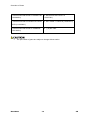
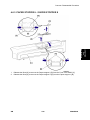
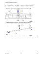
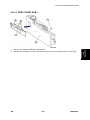
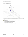
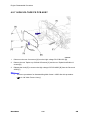
4.4.1 ADF MOTOR, ADF SENSOR PCB ASSY TO MAIN PCB ASSY
1. <Back Side>
4. Main PCB Shield plate
2. ADF motor
5. Main PCB ASSY
3. ADF sensor PCB ASSY
SM
4-9
M085/M086
Harness Routing
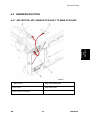
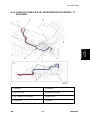
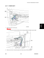
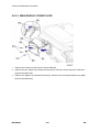
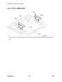
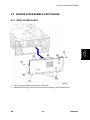
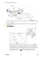
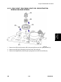
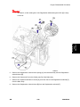
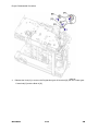
4.4.2 NCU PCB, BATTERY ASSY, SPEAKER UNIT ASSY TO MAIN
PCB ASSY
1. Main PCB ASSY
3. Battery ASSY
2. NCU PCB
4. Speaker unit ASSY plate
M085/M086
4-10
SM
Harness Routing
Replacement
and
Adjustment
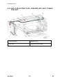
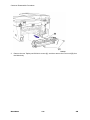
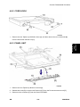
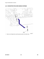
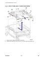
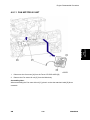
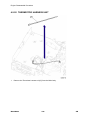
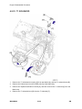
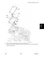
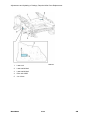
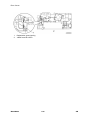
4.4.3 DOCUMENT SCANNER UNIT, PANEL PCB ASSY
1. Main shield cover plate
3. Document scanner unit
2. Main PCB ASSY
4. Panel PCB ASSY
SM
4-11
M085/M086
Harness Routing
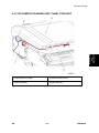
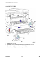
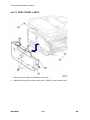
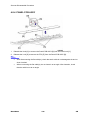
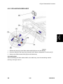
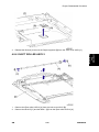
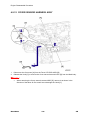
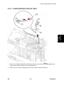
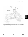
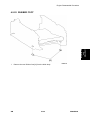
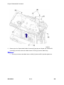
4.4.4 FUSER UNIT
1. PS PCB unit
3. Eject sensor PCB ASSY
2. Fuser unit
M085/M086
4-12
SM
Harness Routing
Replacement
and
Adjustment
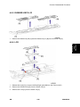
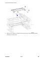
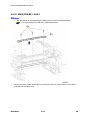
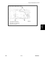
4.4.5 FG HARNESS
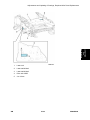
1. <Back side>
4. <Left side>
2. Laser unit
5. Main PCB ASSY
3. FG harness
SM
4-13
M085/M086
Harness Routing
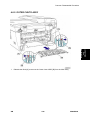
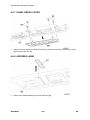
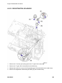
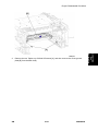
4.4.6 MAIN FRAME R ASSY
1. Front cover sensor
4. PS PCB unit
2. Toner LED PCB ASSY
5. SW holder
3. Fan motor 60 unit
6. Inlet harness ASSY
M085/M086
4-14
SM
Harness Routing
Replacement
and
Adjustment
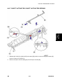
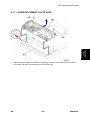
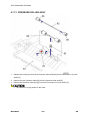
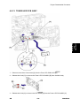
4.4.7 TONER LED PCB ASSY / LVPS PCB UNIT / MAIN PCB ASSY /
REGISTRATION FRONT SENSOR PCB ASSY /
REGISTRATION REAR SENSOR PCB ASSY
1. Main PCB ASSY (Main Frame L ASSY)
5. Toner LED PCB ASSY
2. <Back side>
6. Registration rear sensor PCB ASSY
3. <Right side>
7. Registration front sensor PCB ASSY
4. PS PCB unit
SM
4-15
M085/M086
Harness Routing
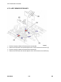
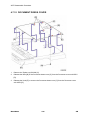
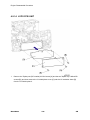
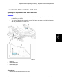
4.4.8 TONER SENSOR PCB UNIT ASSY / NEW TONER SENSOR
HARNESS ASSY
1. <Left side>
4. Toner sensor PCB unit ASSY
2. New toner sensor harness ASSY
5. Main PCB ASSY
3. <Front side>
M085/M086
4-16
SM
Harness Routing
Replacement
and
Adjustment
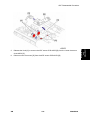
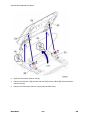
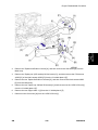
4.4.9 HIGH-VOLTAGE PS PCB / REGISTRATION SOLENOID / T1
SOLENOID
1. <Left side>
5. T1 solenoid
2. Drive sub ASSY
6. Registration solenoid
3. High-voltage PS PCB ASSY
7. <Bottom side>
4. <Front side>
8. <Left side>
SM
4-17
M085/M086
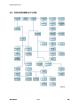
Disassemble Flow
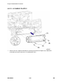
4.5 DISASSEMBLE FLOW
M085/M086
4-18
SM
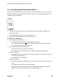
Common Disassemble Procedure
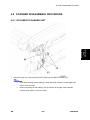
4.6 COMMON DISASSEMBLE PROCEDURE
Replacement
and
Adjustment
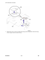
Preparation
Prior to proceeding with the disassembly procedure,
1.
2.
SM
Unplug
the AC cord [A],
the modular jack of the telephone line [B],
the USB cable [C], if connected,
the modular jack of the external telephone set if connected.
Remove
the Paper tray [D],
the Toner cartridge and Drum unit [E]
4-19
M085/M086
Common Disassemble Procedure
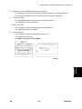
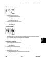
4.6.1 SEPARATION PAD ASSY
1.
Lift up the Separation pad ASSY [A].
2.
Release the Boss [B] to remove the Separation pad ASSY [A] from the Paper tray unit [C].
3.
Remove the Separation pad spring [D] from the Paper tray unit [C].
M085/M086
4-20
SM
Common Disassemble Procedure
Replacement
and
Adjustment
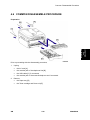
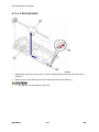
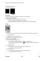
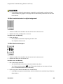
4.6.2 FRONT COVER ASSY
1.
Open the Front cover ASSY [A].
2.
Release the Hook [B] to remove the DEV joint link [C] from the Front cover ASSY [A].
SM
4-21
M085/M086
Common Disassemble Procedure
3.
Release the Hook [A] of the Front cover ASSY [B] from the Front cover top [C].
4.
Remove the Boss [D] of the Front chute ASSY [E], and then remove the Front cover ASSY
[B] from the Main body.
M085/M086
4-22
SM
Common Disassemble Procedure
Replacement
and
Adjustment
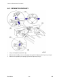
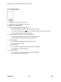
4.6.3 PAPER STOPPER L / PAPER STOPPER S
1.
Release the Boss [A] to remove the Paper stopper L [B] from the Front cover ASSY [C].
2.
Release the Boss [A] to remove the Paper stopper S [D] from the Paper stopper L [B].
SM
4-23
M085/M086
Common Disassemble Procedure
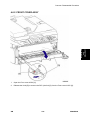
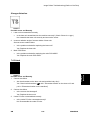
4.6.4 BACK COVER
1.
Open the Back cover [A].
2.
Release the Boss [B] of the Outer chute ASSY [C] from the Back cover [A].
3.
Release the Hook [D] from the Side cover R ASSY [E].
4.
Slide the Back cover [A] from the Main body, and remove it.
M085/M086
4-24
SM
Common Disassemble Procedure
Replacement
and
Adjustment
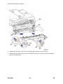
4.6.5 OUTER CHUTE ASSY
1.
SM
Release the Boss [A] to remove the Outer chute ASSY [B] from the Main body.
4-25
M085/M086
Common Disassemble Procedure
4.6.6 FUSER COVER ASSY
1.
Pull down the Fuser cover ASSY [A].
2.
Remove the Fuser cover ASSY [A] from the Main body.
M085/M086
4-26
SM
Common Disassemble Procedure
Replacement
and
Adjustment
4.6.7 EJECT ACTUATOR / EJECT ACTUATOR SPRING
1.
Release the Hook [A] to slide the Eject actuator [B], and then remove the Eject actuator [B]
from the Fuser cover ASSY [C].
2.
SM
Remove the Eject actuator spring [D] from the Eject actuator [B].
4-27
M085/M086
Common Disassemble Procedure
4.6.8 EJECT ROLLER ASSY 1 / BUSH C / BUSH R / BUSH L
1.
Release the Hook [A] of the Bush C [B] from the Fuser cover ASSY [C].
2.
Remove the Eject roller ASSY 1 [D] from the Fuser cover ASSY [C].
3.
Remove the Bush C [A], the Bush R [B] and the Bush L [C] from the Eject roller ASSY 1 [D].
M085/M086
4-28
SM
Common Disassemble Procedure
Replacement
and
Adjustment
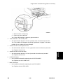
4.6.9 JOINT COVER SUB CHUTE ASSY
1.
Remove the two Taptite bind B M4x12 screws [A], and then remove the Joint cover sub
chute ASSY [B] from the Main body.
SM
4-29
M085/M086
Common Disassemble Procedure
4.6.10 INNER CHUTE ASSY
1.
Remove the two Taptite bind B M4x12 screws [A], and then remove the Inner chute ASSY
[B] from the Main body.
M085/M086
4-30
SM
Common Disassemble Procedure
1.
Disconnect the Connector [A].
2.
SM
Replacement
and
Adjustment
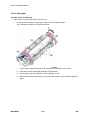
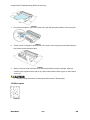
4.6.11 FUSER UNIT
Pull out the Connector [A] from the Housing part [B] of the Main body left side.
Disconnect the two Connectors [A] from the Eject sensor PCB ASSY [B].
4-31
M085/M086
Common Disassemble Procedure
3.
Remove the two Taptite pan B M4x14 screws [A], and then remove the Fuser unit [B] from
the Main body.
M085/M086
4-32
SM
Common Disassemble Procedure
Replacement
and
Adjustment
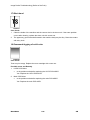
4.6.12 CORNER COVER
1.
Remove the Taptite bind B M4x12 screw [A].
2.
Release the Hook [B] to remove the Corner cover [C] from the Main body.
SM
4-33
M085/M086
Common Disassemble Procedure
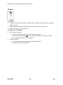
4.6.13 SIDE COVER L ASSY
1.
Remove the two Taptite bind B M4x12 screws [A].
2.
Release the Hook [B] to remove Side cover L ASSY [C] from the Main body.
M085/M086
4-34
SM
Common Disassemble Procedure
1.
Remove the Taptite bind B M4x12 screw [A].
2.
Release the Hook [B] to remove the Side cover sub L [C] from the Side cover L ASSY [D].
SM
4-35
M085/M086
Replacement
and
Adjustment
4.6.14 SIDE COVER SUB L
Common Disassemble Procedure
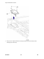
4.6.15 MAIN SHIELD COVER PLATE
1.
Remove the Ferrite core [A] from the Core holder [B].
2.
Remove the two Taptite cup S M3x6 SR screws [C], and then remove the two FG harness
[D] from the Main body.
3.
Remove the Taptite cup S M3x6 SR screw [C], and then remove the Main shield cover plate
[E] from the Main body.
M085/M086
4-36
SM
ADF Disassemble Procedure
4.7 ADF DISASSEMBLE PROCEDURE
Replacement
and
Adjustment
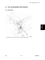
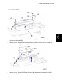
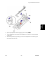
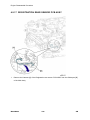
4.7.1 ADF UNIT
1.
SM
Remove the two Connectors [A] from the Main PCB ASSY [B].
4-37
M085/M086
ADF Disassemble Procedure
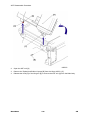
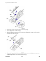
2.
Open the ADF unit [A].
3.
Remove the Taptite bind B M4x12 screw [B] from the Hinge ASSY L [C].
4.
Release the Hook [D] of the Hinge R [E] to remove the ADF unit [A] from the Main body.
M085/M086
4-38
SM
ADF Disassemble Procedure
Replacement
and
Adjustment
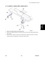
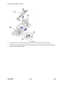
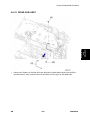
4.7.2 HINGE R / HINGE ARM / HINGE ASSY L
1.
Remove the Hinge R [A] from the Hinge arm [B].
2.
Remove the Taptite bind B M4x12 screw [C], and then remove the Hinge arm [B] from the
ADF unit [D].
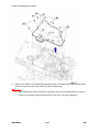
3.
Remove the two Taptite cup B M3x10 screws [E] and the Taptite cup S M3x12 screw [F],
and then remove the Hinge ASSY L [G] from the ADF unit [D].
SM
4-39
M085/M086
ADF Disassemble Procedure
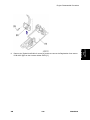
4.7.3 ADF COVER ASSY
1.
Open the ADF cover [A].
2.
Release the Boss [B] to remove the ADF cover [A] from the ADF unit [C].
M085/M086
4-40
SM
ADF Disassemble Procedure
Replacement
and
Adjustment
4.7.4 GEAR COVER
1.
SM
Release the Hook [A] to remove the Gear cover [B] from the ADF unit [C].
4-41
M085/M086
ADF Disassemble Procedure
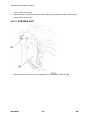
4.7.5 DOCUMENT SEPARATOR ROLLER SHAFT
1.
Remove the Separator roller shaft ASSY [A] from the ADF unit [B].
2.
Remove the Separator roller bushing [C] from the Separator roller shaft ASSY [A].
M085/M086
4-42
SM
ADF Disassemble Procedure
Replacement
and
Adjustment
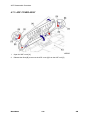
4.7.6 UPPER DOCUMENT CHUTE ASSY
1.
Remove the four Taptite cup B M3x10 screws [A].
2.
Release the Hook [B] to remove the Upper document chute ASSY [C] from the ADF unit
[D].
SM
4-43
M085/M086
ADF Disassemble Procedure
3.
Release the Hook to remove the ADF plate spring [A] and the Separation rubber ASSY [B]
from the Upper document chute ASSY [C].
M085/M086
4-44
SM
ADF Disassemble Procedure
Replacement
and
Adjustment
4.7.7 LOWER DOCUMENT CHUTE ASSY
1.
Remove the two Taptite cup B M3x10 screws [A], and then remove the Lower document
chute ASSY [B] from the Document cover sub ASSY [C].
SM
4-45
M085/M086
ADF Disassemble Procedure
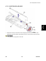
4.7.8 ADF SENSOR PCB ASSY
1.
Pull the Hook [A] to slide the Document front actuator [B].
2.
Remove the Document front actuator [B] from the Lower document chute ASSY [C].
3.
Pull the Hook [A] to slide the Document rear actuator [D].
4.
Remove the Document rear actuator [D] from the Lower document chute ASSY [C].
M085/M086
4-46
SM
5.
Release the Hook [A] to remove the ADF sensor PCB ASSY [B] from the Lower document
chute ASSY [C].
6.
SM
Disconnect the Connector [D] from the ADF sensor PCB ASSY [B].
4-47
M085/M086
Replacement
and
Adjustment
ADF Disassemble Procedure
ADF Disassemble Procedure
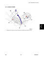
4.7.9 LF ROLLER ASSY
1.
Release the Hook [A] to remove the LF roller bushing [B] from the Lower document chute
ASSY [C].
2.
Remove the LF roller ASSY [D] from the Lower document chute ASSY [C].
Be careful not to get grease on the roller.
M085/M086
4-48
SM
ADF Disassemble Procedure
Replacement
and
Adjustment
4.7.10 EJECTION ROLLER ASSY
1.
Release the Hook [A] of the Ejection roller bushing [B], and then slide the Ejection roller
ASSY [C] to remove the Ejection roller ASSY [C] from the Lower document chute ASSY [D].
SM
Be careful not to get grease on the roller.
4-49
M085/M086
ADF Disassemble Procedure
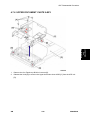
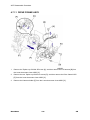
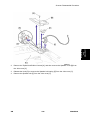
4.7.11 DRIVE FRAME ASSY
1.
Remove the Taptite cup S M3x6 SR screw [A], and then remove the FG harness [B] from
the Lower document chute ASSY [C].
2.
Remove the two Taptite cup B M3x10 screws [D], and then remove the Drive frame ASSY
[E] from the Lower document chute ASSY [C].
3.
Remove the Harness holder [F] from the Lower document chute ASSY [C].
M085/M086
4-50
SM
ADF Disassemble Procedure
Replacement
and
Adjustment
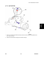
4.7.12 ADF MOTOR
1.
Remove the Taptite bind S M3x6 screw [A], and then remove the ADF motor [B] from the
Drive frame ASSY [C].
2.
SM
Remove the ADF harness unit [D] from the ADF motor [B].
4-51
M085/M086
ADF Disassemble Procedure
4.7.13 PRESSURE ROLLER ASSY
1.
Release the Hook [A] to remove the Pressure roller ASSY [B] from the Document cover sub
ASSY [C].
2.
Remove the two Pressure rollers [D] from the Pressure roller shaft [E].
3.
Remove the Pressure roller spring [F] from the Document cover sub ASSY [C].
Be careful not to get grease on the roller.
M085/M086
4-52
SM
ADF Disassemble Procedure
Replacement
and
Adjustment
4.7.14 DOCUMENT STOPPER
1.
Open the Document stopper [A].
2.
Release the Boss [B] to remove the Document stopper [A] from the Document dress cover
[C].
SM
4-53
M085/M086
ADF Disassemble Procedure
4.7.15 DOCUMENT DRESS COVER
1.
Remove the Taptite cup B M3x8 [A].
2.
Release the Boss [B] of the Document dress cover [C] from the Document cover sub ASSY
[D].
3.
Release the Hook [E] to remove the Document dress cover [C] from the Document cover
sub ASSY [D].
M085/M086
4-54
SM
Scanner Disassemble Procedure
4.8 SCANNER DISASSEMBLE PROCEDURE
Replacement
and
Adjustment
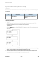
4.8.1 DOCUMENT SCANNER UNIT
1.
Disconnect the two connectors [A] and FFC [B] from the Main PCB ASSY [C].
After disconnecting the flat cable(s), check that each cable is not damaged at its
end or short-circuited.
When connecting the flat cable(s), do not insert it at an angle. After insertion,
check that the cable is not at an angle.
SM
4-55
M085/M086
Scanner Disassemble Procedure
2.
Open the Document scanner unit [A].
3.
Remove the Pull arm L [B] and the Pull arm R [C] from the Boss [D] of the Document
scanner unit [A].
4.
Remove the Document scanner unit [A] from the Main body.
M085/M086
4-56
SM
Scanner Disassemble Procedure
4.8.2 CORD HOOK
1.
Remove the two Taptite cup B M3x8 screws [A], and then remove the two cord hooks [B]
from the Document scanner unit [C].
Replacement
and
Adjustment
4.8.3 PANEL UNIT
1.
Remove the four Taptite cup B M3x10 screws [A].
2.
Release the Hook [B] to remove the Panel unit [C] from the Document scanner unit [D].
3.
Disconnect the connector [E] from the Panel PCB ASSY.
SM
4-57
M085/M086
Scanner Disassemble Procedure
4.8.4 PANEL PCB ASSY
1.
Release the Hook [A] to remove the Panel PCB ASSY [B] from the Panel unit [C].
2.
Release the Lock [D] to remove the FFC [E] from the Panel PCB ASSY [B].
After disconnecting the flat cable(s), check that each cable is not damaged at its end or
short-circuited.
When connecting the flat cable(s), do not insert it at an angle. After insertion, check
that the cable is not at an angle.
M085/M086
4-58
SM
Scanner Disassemble Procedure
4.8.5 RUBBER KEYS L/R
1.
Remove the Rubber keys R [A] and the Rubber keys L [B] from the Panel unit [C].
Replacement
and
Adjustment
4.8.6 LCD
1.
Release the Hook [A] to remove the Back light guide [B] from the Panel unit [C].
2.
Remove the Diffusion film [D] from the Panel unit [C].
3.
Remove the LCD [E] from the Panel unit [C].
SM
4-59
M085/M086
Scanner Disassemble Procedure
4.8.7 PANEL DRESS COVER
1.
Remove the four Taptite cup B M3x8 screws [A], and then remove the Panel dress cover
[B] from the Panel unit [C].
4.8.8 ADDRESS LABEL
1.
Remove the Address label [A] from the Panel unit [B].
M085/M086
4-60
SM
Scanner Disassemble Procedure
Replacement
and
Adjustment
4.8.9 PULL ARM L/R
1.
Remove the Pull arm spring ADF L [A] and the Pull arm L [B] from the Joint cover [C].
2.
Remove the Pull arm spring ADF R [D] and the Pull arm R [E] from the Joint cover [C].
SM
4-61
M085/M086
Scanner Disassemble Procedure
4.8.10 PULL ARM GUIDE
1.
Remove the two Lock claws [A] to remove the two Pull arm guides [B] from the Joint cover
[C].
M085/M086
4-62
SM
Scanner Disassemble Procedure
1.
Remove the Screw pan (S/P washer) M3.5x6 screw [A], and then remove the FG harness
[B] from the NCU shield [C].
2.
Remove the two Taptite bind B M4x12 screws [D], and then remove the NCU shield [C]
from the Joint cover [E].
3.
Turn over the NCU housing [A].
4.
Remove the two Taptite cup S M3x6 SR screws [B], and then remove the NCU PCB [C]
SM
4-63
M085/M086
Replacement
and
Adjustment
4.8.11 NCU PCB
Scanner Disassemble Procedure
from the NCU housing [A].
5.
Disconnect the Connector [D] from the NCU PCB [C], and then pull out the Connector [D]
from the NCU housing [A].
4.8.12 SPEAKER UNIT
1.
Disconnect the Connector [A] of the Speaker unit from the Main PCB ASSY [B].
M085/M086
4-64
SM
Replacement
and
Adjustment
Scanner Disassemble Procedure
2.
Remove the Taptite bind B M4x12 screw [A], and then remove the Speaker cover [B] from
the Joint cover [C].
3.
Release the Hook [D] to remove the Speaker hold spring [E] from the Joint cover [C].
4.
Remove the Speaker unit [F] from the Joint cover [C].
SM
4-65
M085/M086
Scanner Disassemble Procedure
4.8.13 BATTERY ASSY
1.
Disconnect the connector [A], and then remove the Battery ASSY [B] from the Joint cover
[C].
There is a danger of explosion if the battery is incorrectly replaced.
Do not disassemble or recharge the battery.
Do not dispose of the battery in fire.
Used batteries should be disposed of according to the local regulations.
Use a genuine spare part when you replace the battery.
M085/M086
4-66
SM
Engine Disassemble Procedure
4.9 ENGINE DISASSEMBLE PROCEDURE
Replacement
and
Adjustment
4.9.1 SIDE COVER R ASSY
1.
Remove the two Taptite bind B M4x12 screws [A].
2.
Release the Hook [B] to remove the Side cover R ASSY [C] from the Main body.
SM
4-67
M085/M086
Engine Disassemble Procedure
4.9.2 REGISTRATION GROUNDING SPRING
1.
Remove the Registration grounding spring [A] from the Main body.
M085/M086
4-68
SM
Engine Disassemble Procedure
Replacement
and
Adjustment
4.9.3 ROLLER HOLDER ASSY
1.
Release the Boss [A] of the Roller holder ASSY [B] from the Link arm [C].
2.
Press the Rib [D] of the Paper feed frame [E], then slide the Separation R shaft bush [F].
3.
Remove the Roller holder ASSY [B] from the Main body.
Assembling Note:
When assembling the Roller holder ASSY to the Main body, note the assembling method
referring to the figure above.
SM
4-69
M085/M086
Engine Disassemble Procedure
When the Separation R shaft bush [A] does not slide across correctly, place the Rib [B]
of the Bush 6 [C] while aligning with the Groove [D] of the Main body shaft hole from
the Main frame L ASSY side.
M085/M086
4-70
SM
Engine Disassemble Procedure
Replacement
and
Adjustment
4.9.4 MAIN PCB ASSY
1.
Disconnect the five FFCs [A] and the eight Connectors [B] from the Main PCB ASSY [C].
2.
Remove the four Taptite cup S M3x6 SR screws [D], and then remove the FG harness
ASSY [E] and the Main PCB ASSY [C] from the Main body.
After disconnecting the flat cable(s), check that each cable is not damaged at its end or
short-circuited.
When connecting the flat cable(s), do not insert it at an angle. After insertion, check
that the cable is not at an angle.
Assembling Note:
If the FG harness ASSY which comes from the Laser unit is not connected, the Laser unit may
break down or not function correctly.
Replacement Main PCB Note:
When replace the main PCB, the function of the I FAX disappears.
Contact the customer to download the I FAX again.
SM
4-71
M085/M086
Engine Disassemble Procedure
4.9.5 JOINT COVER ASSY / PAPER SUPPORTER
1.
Remove the five Taptite bind B M4x12 screws [A].
2.
Release the Hook [B] to remove the Joint cover ASSY [C] from the Main body.
M085/M086
4-72
SM
Engine Disassemble Procedure
3.
Release the Boss [A] to remove the Paper supporter [B] from the Joint cover ASSY [C].
Replacement
and
Adjustment
4.9.6 EJECT ROLLER ASSY 2
1.
Remove the Eject roller ASSY 2 [A] from the Joint cover ASSY [B].
2.
Remove the Bush R [C] and the Bush L [D] from the Eject roller ASSY 2 [A].
SM
4-73
M085/M086
Engine Disassemble Procedure
4.9.7 HIGH-VOLTAGE PS PCB ASSY
1.
Disconnect the two Connectors [A] from the High-voltage PS PCB ASSY [B].
2.
Remove the two Taptite cup S M3x6 SR screws [C] and the two Taptite bind B M4x12
screws [D].
3.
Release the Hook [E] to remove the High-voltage PS PCB ASSY [B] from the Drive sub
ASSY [F].
There are procedures for disassembling Main frame L ASSY after this procedure.
(
M085/M086
p.4-106 "Main Frame L Assy")
4-74
SM
Engine Disassemble Procedure
Replacement
and
Adjustment
4.9.8 NEW TONER SENSOR HARNESS ASSY
1.
Release the Hook [A] to remove the New toner sensor harness ASSY [B] from the Main
body.
SM
Be careful not to damage the Hook of the New toner sensor harness ASSY.
4-75
M085/M086
Engine Disassemble Procedure
4.9.9 FILTER ASSY
1.
Remove the Filter ASSY [A] from the Main body.
M085/M086
4-76
SM
Engine Disassemble Procedure
Replacement
and
Adjustment
4.9.10 LASER UNIT
1.
Remove the Core [A] from the Main body.
2.
Remove the three Taptite cup S M3x6 SR screws [B] and the Taptite pan (S/P washer) S
M3x8 screw [C], and then remove the Laser unit [D] from the Main body.
SM
Ensure when you remove the Laser unit [D] that the DEV joint link [E] is pulled out.
4-77
M085/M086
Engine Disassemble Procedure
3.
Remove the Taptite cup S M3x6 SR screw [A], and then remove the FG harness ASSY [B]
from the Laser unit [C].
4.
Remove the Taptite cup S M3x6 SR screw [A], and then remove the Air duct [D] from the
Laser unit [C].
When replacing the Laser unit, replace the Serial label [A] attached on the Drive
sub ASSY [B] with the new one supplied with a new Laser unit. If an extra Serial
label is supplied with a new unit as spare. Make sure to throw the spare label away
after replacing the Laser unit, *** it is necessary to input the new Laser unit
characteristics information.*** (
M085/M086
p.4-121 "If You Replace the Laser Unit")
4-78
SM
Engine Disassemble Procedure
Replacement
and
Adjustment
4.9.11 FAN MOTOR 60 UNIT
1.
Disconnect the Connector [A] from the Toner LED PCB ASSY [B].
2.
Remove the Fan motor 60 unit [C] from the Main body.
Assembling Note:
When assembling the Fan motor 60 unit [C], place it so that the attached Label [D] faces
outwards.
SM
4-79
M085/M086
Engine Disassemble Procedure
4.9.12 COVER SENSOR HARNESS ASSY
1.
Disconnect the Connector [A] from the Toner LED PCB ASSY [B].
2.
Release the Hook [C] to remove the Cover sensor harness ASSY [D] from the Main body.
When removing the Cover sensor harness ASSY [D], remove it as shown in the
direction of the allow 2b. Be careful not to damage the Hook [C].
M085/M086
4-80
SM
Engine Disassemble Procedure
Replacement
and
Adjustment
4.9.13 TONER LED PCB ASSY
1.
Disconnect the three Connectors [A] from the Toner LED PCB ASSY [B].
2.
Release the Hook [C] to remove the Toner LED PCB ASSY [B] from the Main body.
3.
Release the Hook [A] to remove the LED holder [B] from the Toner LED PCB ASSY [C].
SM
4-81
M085/M086
Engine Disassemble Procedure
4.9.14 LVPS PCB UNIT
1.
Remove the Taptite pan (S/P washer) M3.5x6 screw [A] and the two Taptite cup S M3x6 SR
screws [B], and then remove the LV shield plate cover [C] and the LV insulation sheet [D]
from the LV Shield plate 2.
M085/M086
4-82
SM
Replacement
and
Adjustment
Engine Disassemble Procedure
2.
Remove the Taptite bind B M4x12 screw [A], and then remove the SW holder [B] from the
Main body.
3.
Remove the Taptite pan (S/P washer) M3.5x6 screw [C], and then remove the FG harness
ASSY [D] of the Inlet harness ASSY [E] from the LV shield plate 2 [F].
4.
Remove the two Taptite flat B M3x10 screws [G], and then remove the Inlet harness ASSY
[E] from the Main body.
5.
Remove the two Taptite cup S M3x6 SR screws [H], and then remove the LVPS PCB unit [I]
from the LV shield plate 2 [F].
6.
Remove the two Edge holder 3 [J] from the LV shield plate 2 [F].
7.
Disconnect the Connector [K] from the LVPS PCB unit [I].
SM
4-83
M085/M086
Engine Disassemble Procedure
4.9.15 LV SHIELD PLATE 2
1.
Remove the two Taptite bind B M4x12 screws [A] and the two Taptite cup S M3x6 SR
screws [B], and then remove the LV shield plate 2 [C].
M085/M086
4-84
SM
Engine Disassemble Procedure
Replacement
and
Adjustment
4.9.16 REGISTRATION FRONT SENSOR PCB ASSY
1.
Remove the Harness [A] of the Registration front sensor PCB ASSY and the Registration
rear sensor PCB ASSY from the Guide part [B] of the Main body.
SM
4-85
M085/M086
Engine Disassemble Procedure
2.
Remove the two Taptite bind B M3x10 screws [A], and then remove the Actuator holder
ASSY [B] from the Main body.
M085/M086
4-86
SM
Replacement
and
Adjustment
Engine Disassemble Procedure
3.
Remove the Registration actuator spring [A] from the Hook part [B].
4.
Turn the Registration front actuator [C] at 90 degrees in the direction of counterclockwise
as the arrow 4.
5.
Slide the Registration front actuator [C] to remove the Registration front actuator [C] from
the Actuator holder ASSY [D].
SM
4-87
M085/M086
Engine Disassemble Procedure
6.
Loosen the tip of the Edge actuator spring [A] from the Actuator holder ASSY [B].
7.
Release the Hook [C] and Slide the Edge actuator [D] to remove the Edge actuator [D] from
the Actuator holder ASSY [B].
M085/M086
4-88
SM
8.
Remove the Taptite bind B M3x10 screw [A], and then remove the Registration front sensor
PCB ASSY [B] from the Actuator holder ASSY [C].
SM
4-89
M085/M086
Replacement
and
Adjustment
Engine Disassemble Procedure
Engine Disassemble Procedure
4.9.17 REGISTRATION REAR SENSOR PCB ASSY
1.
Remove the Harness [A] of the Registration rear sensor PCB ASSY from the Guide part [B]
of the Main body.
M085/M086
4-90
SM
Replacement
and
Adjustment
Engine Disassemble Procedure
2.
Remove the two Taptite bind B M3x10 screws [A], and then remove the Rear actuator
holder ASSY [B] from the Main body.
SM
4-91
M085/M086
Engine Disassemble Procedure
3.
Remove the Actuator spring rear [A] from the Hook part [B].
4.
Turn the Registration actuator rear [C].
5.
Slide the Registration actuator rear [C] to remove the Registration actuator rear [C] from the
Rear actuator holder ASSY [D].
6.
Remove the Taptite bind B M3x10 screw [A], and then remove the Registration rear sensor
PCB ASSY [B] from the Rear actuator holder ASSY [C].
M085/M086
4-92
SM
Engine Disassemble Procedure
Replacement
and
Adjustment
4.9.18 DRIVE SUB ASSY
1.
Remove the Taptite cup S M3x6 SR screw [A] and the Taptite bind B M4x12 screw [B] on
the Main frame L Assy, and then remove the Under FG wire [C] from the Main body.
SM
4-93
M085/M086
Engine Disassemble Procedure
2.
Remove the Taptite cup S M3x6 SR screw [A] and the nine Taptite bind B M4x12 screws [B],
and then remove the Drive sub ASSY [C] from the Main body.
When removing the Drive sub ASSY, Ensure the left side of the Main body is at the top
as shown in the above figure because there is the risk of the gears falling off.
M085/M086
4-94
SM
Engine Disassemble Procedure
Replacement
and
Adjustment
4.9.19 DEV JOINT / DEV GEAR JOINT 53R / REGISTRATION
PENDULUM GEAR SPRING
1.
Remove the DEV joint [A] and the DEV joint spring [B] from the DEV gear joint/53R [C].
2.
Remove the DEV gear joint/53R [C] from the Drive sub ASSY [D].
3.
Remove the Registration pendulum gear spring [E] from the Drive sub ASSY [D].
SM
4-95
M085/M086
Engine Disassemble Procedure
4.9.20 THERMISTOR HARNESS UNIT
1.
Remove the Thermistor harness unit [A] from the Main body.
M085/M086
4-96
SM
Engine Disassemble Procedure
Replacement
and
Adjustment
4.9.21 TONER SENSOR PCB UNIT ASSY
1.
Remove the Taptite bind B M3x10 screw [A], and then remove the Link stopper [B] and the
Toner sensor PCB unit ASSY [C] from the Main body.
2.
SM
Remove the PT sensor holder [D] from the Toner sensor PCB unit ASSY [C].
4-97
M085/M086
Engine Disassemble Procedure
4.9.22 REGISTRATION SOLENOID
1.
Remove the T1 sector gear spring [A] from the T1 gear 38/31 sector [B].
2.
Remove the T1 gear 38/31 sector [B] from the Main body.
3.
Release the Hook [C] to remove the Registration gear 25 terminal [D] from the Main body.
4.
Remove the Registration differential gear ASSY [E] from the Main body.
M085/M086
4-98
SM
Engine Disassemble Procedure
Be careful, as the inside gear of the Registration differential gear ASSY [E] is easy
Replacement
and
Adjustment
to fall out.
5.
Remove the Registration solenoid lever spring [A] from the Main body and the Registration
solenoid lever [B].
6.
Remove the Harness [C] from the Guide part [D] of the Main body.
7.
Remove the Taptite bind B M3x10 screw [E], and then remove the Registration solenoid [F]
from the Main body.
8.
SM
Remove the Registration solenoid lever [B] from the Registration solenoid [F].
4-99
M085/M086
Engine Disassemble Procedure
4.9.23 T1 SOLENOID
1.
Remove the T1 solenoid lever spring [A] from the Main body and the T1 solenoid lever [B].
2.
Remove the Harness [C] from the Guide part [D] of the Main body.
3.
Remove the Taptite bind B M3x10 screw [E], and then remove the T1 solenoid [F] from the
Main body.
4.
Remove the T1 solenoid lever [B] from the T1 solenoid [F].
M085/M086
4-100
SM
Engine Disassemble Procedure
Replacement
and
Adjustment
4.9.24 MAIN SHIELD PLATE / EJECT SENSOR PCB ASSY
1.
Remove the three Taptite bind B M3x10 screws [A], and then remove the FU front paper
guide [B] from the Main body.
SM
4-101
M085/M086
Engine Disassemble Procedure
2.
Remove the two Taptite cup S M3x6 SR screws [A], and then remove the Chute ground
plate [B] from the Main body.
M085/M086
4-102
SM
Replacement
and
Adjustment
Engine Disassemble Procedure
3.
Remove the Main PCB sheet [A] from the Main shield plate [B].
4.
Remove the three Taptite bind B M4x12 screws [C], and then remove the Main shield plate
[B] from the Main body.
SM
4-103
M085/M086
Engine Disassemble Procedure
5.
Release the Hook [A] to remove the Eject sensor PCB ASSY [B] from the Main body.
M085/M086
4-104
SM
Engine Disassemble Procedure
Replacement
and
Adjustment
4.9.25 RUBBER FOOT
1.
SM
Remove the two Rubber feet [A] from the Main body.
4-105
M085/M086
Engine Disassemble Procedure
4.9.26 MAIN FRAME L ASSY
The procedure for disassembling the Main frame L ASSY as mentioned after
p.4-74 "High-Voltage PS PCB Assy" is described below.
1.
Remove the three Taptite bind B M3x10 screws [A], and then remove the FU front paper
guide [B] from the Main body.
M085/M086
4-106
SM
2.
Remove the two Taptite cup S M3x6 SR screws [A], and then remove the Chute ground
plate [B] from the Main body.
SM
4-107
M085/M086
Replacement
and
Adjustment
Engine Disassemble Procedure
Engine Disassemble Procedure
3.
Release the Hook [A] to remove the Registration gear 25 terminal [B], the two Feeder gear
17 terminals [C] and the Bush 6 [D].
M085/M086
4-108
SM
Replacement
and
Adjustment
Engine Disassemble Procedure
4.
Remove the Taptite cup S M3x6 SR screw [A] and the Taptite bind B M4x12 screw [B] on
the Main frame L ASSY, and then remove the Under FG wire [C] from the Main body.
SM
4-109
M085/M086
Engine Disassemble Procedure
5.
Remove the four Taptite bind B M4x12 screws [A] and the two Taptite cup S M3x6 SR
screws [B], and then remove the Main frame L ASSY [C] from the Main body.
Ensure you remove the Main frame L ASSY [C] with the DEV joint link pulled out.
M085/M086
4-110
SM
Engine Disassemble Procedure
SM
[A]: Taptite bind B M4x12
[B]: Taptite cup S M3x6 SR
[C]: Drive sub ASSY
Replacement
and
Adjustment
<Upper surface of Main frame L ASSY>
4-111
M085/M086
Adjustments and Updating of Settings, Required After Parts Replacement
4.10 ADJUSTMENTS AND UPDATING OF SETTINGS,
REQUIRED AFTER PARTS REPLACEMENT
4.10.1 IF YOU REPLACE THE MAIN PCB
When replace the main PCB, the function of the I FAX disappears. Contact the
customer to download the I FAX again.
<What to do when replacing the main PCB>
EEPROM parameter initialization of main PCB (Maintenance mode: code 01)
Operational check of control panel button (Maintenance mode: code 13)
Operational check of sensors (Maintenance mode: code 32)
Acquisition of white level data and set the CIS scanner area (Maintenance mode: code 55)
EEPROM customizing of main PCB (Maintenance mode: code 74)
Setting the serial number
Inputting the adjusted value of the laser scanner
<What you need to prepare>
1.
Computer (Windows® XP or later)
Create folder, for example "ALL2" folder on the C drive.
2.
BrUsbSn.exe file
Copy it into the "ALL2" folder that has been created on the C drive. Extract the copied file
and run "BrUsbSn.exe" file by double-clicking.
3.
USB cable (one piece)
4.
Maintenance USB Printer Driver
Copy it into the "ALL2" folder that has been created on the C drive. Extract the copied file.
Installing the maintenance printer driver
To identify terminals connected via USB interface, the PC requires the corresponding virtual
USB devices to be implemented by the driver. If you connect a number of machines to your PC,
the same number of virtual USB devices will be automatically configured on your PC.
To
prevent virtual USB devices from being configured limitlessly, use the unique driver installation
procedure described below that enables your PC to identify terminals via single virtual USB
device.
1.
Check that the power switch of the machine is turned off. Disconnect the USB cable that
connects the machine with PC.
2.
Turn on your PC and machine.
M085/M086
4-112
SM
Adjustments and Updating of Settings, Required After Parts Replacement
3.
Enter the maintenance mode.
4.
Click the “DPInst.exe” of the Printer Maintenance Driver which has been copied in the
Replacement
and
Adjustment
“ALL2” folder to start.
5.
The screen above appears, indicating the detection of device installation wizard. Click Next
to proceed.
6.
An alert warning message of WHQL appears three times. Click Continue Anyway to
proceed.
SM
4-113
M085/M086
Adjustments and Updating of Settings, Required After Parts Replacement
7.
If the device driver is successfully installed, the screen above appears. Click Finish to
return.
8.
Connect the machine to your PC using the USB cable.
9.
Select “Install the software automatically (Recommended)” and click Next.
M085/M086
4-114
SM
Replacement
and
Adjustment
Adjustments and Updating of Settings, Required After Parts Replacement
10. An alert warning message of WHQL appears. Click Continue Anyway to proceed.
SM
4-115
M085/M086
Adjustments and Updating of Settings, Required After Parts Replacement
11. If the Maintenance USB Printer driver is successfully installed, the screen above appears.
Click Finish to return.
M085/M086
4-116
SM
Adjustments and Updating of Settings, Required After Parts Replacement
EEPROM parameter initialization of main PCB (Maintenance mode: code
01)
Refer to
p.5-4 "EEPROM Parameter Initialization (Function code 01, 91)", and perform the
EEPROM parameter Initialization of main PCB.
EEPROM customizing of main PCB (Maintenance mode: code 74)
Refer to
p.5-39 "EEPROM Customizing (Function code 74)", and perform the EEPROM
Customizing.
For models in France and surrounding countries, Pan-Nordic, Oceania or Iberia, implement the
setting for Code 74 in Maintenance mode first. Then, implement more detailed settings for Code
52.
Operational check of control panel button (Maintenance mode: code 13)
p.5-17 "Operational Check of Control Panel Button (Function code 13)", and
perform the operational check of control panel PCB.
Operational check of sensors (Maintenance mode: code 32)
Refer to
p.5-19 "Operational Check of Sensors (Function code 32)", and perform the
operational check of sensors.
Acquisition of white level data and set the CIS scanner area (Maintenance
mode: code 55)
Refer to
p.5-38 "Acquisition of White Level Data (Function code 55)", and perform the
acquisition of white level data and CIS scanner area setting.
Setting the serial number
<Procedures>
1.
Connect the PC and machine with the USB cable.
2.
Double-click the BrUsbSn.exe file which has been copied in the “ALL2” folder to start.
SM
4-117
M085/M086
Replacement
and
Adjustment
Refer to
Adjustments and Updating of Settings, Required After Parts Replacement
3.
Click the “Ricoh” of the model menu.
4.
In Port on the BrUsbSn screen, select the port number assigned to the Maintenance USB
Printer. If the port number is unknown, check the Maintenance USB Printer Properties
(
p.4-125 "How to Select the Port Number").
5.
Enter the serial number of the machine into the box on the “Serial No”.
6.
Click the OK button. The serial number is written in the machine.
M085/M086
4-118
SM
Adjustments and Updating of Settings, Required After Parts Replacement
Inputting the adjusted value of the laser scanner
<Procedures>
Double-click the BrUsbSn.exe file to start.
2.
Click the “Ricoh” of the model menu.
3.
In Port on the BrUsbSn screen, select the port number assigned to the Maintenance USB
Replacement
and
Adjustment
1.
Printer. If the port number is unknown, check the Maintenance USB Printer Properties
(
p.4-125 "How to Select the Port Number").
4.
Enter the serial number into the box on the “Laser Scanner Info.” as shown below.
5.
Click the OK button. The correction value of the laser unit is written in the machine.
SM
4-119
M085/M086
Adjustments and Updating of Settings, Required After Parts Replacement
1.
Laser unit
2.
Laser serial label
3.
Laser serial label
4.
Drive sub ASSY
5.
2 to 10mm
M085/M086
4-120
SM
Adjustments and Updating of Settings, Required After Parts Replacement
4.10.2 IF YOU REPLACE THE LASER UNIT
Inputting the adjustment value of the laser unit
When replace the laser unit, attach the serial label with the provided the new laser unit
to the driver sub ASSY.
The input of following the correction value of the laser unit enter the serial label number
Replacement
and
Adjustment
with the provided the new laser unit.
1.
Laser unit
2.
Laser serial label
3.
Laser serial label
4.
Drive sub ASSY
5.
2 to 10mm
<Procedures>
1.
SM
Double-click the BrUsbSn.exe file to start.
4-121
M085/M086
Adjustments and Updating of Settings, Required After Parts Replacement
2.
Click the “Ricoh” of the model menu.
3.
In Port on the BrUsbSn screen, select the port number assigned to the Maintenance USB
Printer. If the port number is unknown, check the Maintenance USB Printer Properties
(
p.4-125 "How to Select the Port Number").
4.
Enter the serial number into the box on the “Laser Scanner Info.” as shown below.
5.
Click the OK button. The corrected value of the laser unit is written in the machine.
M085/M086
4-122
SM
Replacement
and
Adjustment
Adjustments and Updating of Settings, Required After Parts Replacement
SM
1.
Laser unit
2.
Laser serial label
3.
Laser serial label
4.
Drive sub ASSY
5.
2 to 10mm
4-123
M085/M086
Adjustments and Updating of Settings, Required After Parts Replacement
4.10.3 IF YOU REPLACE THE FB UNIT
Acquisition of white level data and set the CIS scanner area
1.
Enter the maintenance mode.
2.
<M085>
Press the 5 button twice.
<M086/M104>
Press the
or
button several times. "MAINTENANCE 55" appears on the LCD, and
then press the OK button. "Press START" appears on the LCD.
3.
Press the Start button.
The white level data will be acquired automatically.
4.
If the procedure is completed, the machine will automatically return to the initial stage of the
maintenance mode.
M085/M086
4-124
SM
Adjustments and Updating of Settings, Required After Parts Replacement
1.
Replacement
and
Adjustment
4.10.4 HOW TO SELECT THE PORT NUMBER
Click start | Printers and Faxes.
The Printers window appears as shown below.
2.
SM
Right-click the Maintenance USB Printer icon.
4-125
M085/M086
Adjustments and Updating of Settings, Required After Parts Replacement
3.
Click Properties.
The Maintenance USB Printer Properties window appears as shown below.
4.
Click the Ports tab.
In this example, the port number assigned to the Maintenance USB Printer is USB001.
M085/M086
4-126
SM
FIRMWARE INSTALLATION
Rev. 11/30/2011
⇒ 4.11 FIRMWARE INSTALLATION
Preparation
Download the below driver & firmware files and save them in an arbitrary folder in your PC
(e.g., C:¥UPDATE)
• SP1200 Series Maintenance Driver
• Engine Firmware
• SP1200 Series filedg32.exe
Installing the SP1200 Series Maintenance Driver
IMPORTANT:
• Once this procedure is performed for a given PC, no more driver/software installations are
required for that PC.
• Before you do this procedure, make sure that the files for the Maintenance USB Printer driver
are already stored on the PC (Windows XP or later).
Installation Steps:
1.
Make sure that both the Machine & PC are turned OFF & not connected to each other.
2.
Turn “ON” the machine. Follow any of below steps to enter the maintenance mode.
• Press the Menu and Start key. Now immediately press the ▲ key four times
to make the machine enter the maintenance mode.
OR
• On the numerical keypad press the Menu, *, 2, 8, 6 and 4 keys in this sequence in a
continuous & smooth manner.
CAUTION:
• If the pressing time gap between keys is long, the machine will EXIT by producing a
“Boo” sound & return to Normal Mode.
• Leave the machine in “MAINTENANCE" mode until next instruction.
The machine will produce long beep & enter into “MAINTENANCE" mode. The LCD display
will change as below.
SM
4-127
M085/M086
FIRMWARE INSTALLATION
Rev. 11/30/2011
3.
Now turn on the PC & Run “DPInst.exe” in folder “SP1200 Series Maintenance Driver”.
4.
When the following screen appears, click “Next” to proceed.
5.
A WHQL alert message will appear three times. Click “Continue Anyway” to proceed.
M085/M086
4-128
SM
FIRMWARE INSTALLATION
Rev. 11/30/2011
6.
If the device driver was successfully installed, the following dialog appears.
Note: The status of the three drivers will be displayed as “Ready to use”.
Click “Finish”.
7.
Accessing the "Maintenance Mode"
Connect the machine in Maintenance Mode (Step 2) to your PC using a USB cable.
When the new hardware detection dialog appears, click "Next" to proceed.
When the following dialog appears, select "Install the software automatically
(Recommended)",
and then click "Next" to proceed.
SM
4-129
M085/M086
FIRMWARE INSTALLATION
8.
Rev. 11/30/2011
When the WHQL alert message appears, click “Continue Anyway” to proceed.
M085/M086
4-130
SM
FIRMWARE INSTALLATION
Rev. 11/30/2011
9.
If the Maintenance Printer Driver is successfully installed, the following dialog appears.
Click “Finish”.
Do above steps for all three drivers.
10. Now turn OFF the machine to exit Maintenance Mode.
11. Accessing the " Firmware Download Mode "
Turn ON the machines while pressing the 5 key of the numerical keypad.
The machine will enter into Firmware Download Mode & LCD display will change as below.
12. Run “SP1200_Series_filedg32.exe".
SM
4-131
M085/M086
FIRMWARE INSTALLATION
Rev. 11/30/2011
13. The Filedrgs window will appear.
Select Maintenance Printer Driver in the Filedrgs window as below..
Now Drag & Drop the Engine Firmware File onto the Filedrgs window.
14. While downloading the firmware the machine beeps intermittently.
After few minutes upon completion, the machine automatically reboots and
return to the standby state.
15. Checking of the Firmware Version
Press the * and # keys at the same time when the machine is on standby
The firmware version appears on the LCD.
16. Press STOP key to return to the Ready Mode.
M085/M086
4-132
SM
SERVICE MAINTENANCE
R E V I S I O N H I S T O RY
P a ge
1
Date
10/11/2011
A d de d /U pd at e d /N ew
Maintenance mode
Maintenance Mode
Rev. 10/11/2011
5. SERVICE MAINTENANCE
5.1 MAINTENANCE MODE
The maintenance mode is exclusively designed for the checking, setting and adjustment of the
machine by using the buttons on the control panel. You can customize the EEPROM according
to the shipment destination of the machine concerned. In addition, you can perform operational
checks of the LCD, control panel PCB and sensors, perform a print test, display the log
information and error codes, and modify worker switches (WSW).
5.1.1 HOW TO ENTER THE MAINTENANCE MODE
To enter maintenance mode in this machine.
Service
Maintenance
Press the following keys within 2 seconds.
Or,
⇒ [Menu/Set] .. [Start] .. [^] .. [^] .. [^] .. [^]
After entering the maintenance mode, the machine beeps for approx. one second and displays
"
" on the LCD, indicating that it is placed in the initial stage of
the maintenance mode, a mode in which the machine is ready to accept entry from the buttons.
In the case of the model with the numeric keys; To exit from the maintenance mode
and switch to standby, press the 9 button twice in the initial stage of the maintenance
mode. In the case of the model without the numeric keys; Press the
or
button.
The "MAINTENANCE 99" appears on the LCD. Then press the OK button, and the
machine returns to the standby state.
Pressing the Stop/Exit button after entering only one digit restores the machine to the
initial stage of the maintenance mode.
If an invalid function code is entered, the machine beeps for one second and returns to
the initial stage of the maintenance mode.
SM
5-1
M085/M086
Maintenance Mode
5.1.2 HOW TO ENTER THE END USER-ACCESSIBLE
MAINTENANCE MODE
The maintenance-mode functions listed on the next section should be accessed by service
personnel only. However, you can allow end users to access some of these under the guidance
of service personnel by phone.
The end user-accessible functions are shaded in the table given on the next section. (codes 06,
09, 10, 11, 12, 25, 43, 53, 54, 80, 82, 87 and 91)
Function code 10 accesses the worker switches, each of which has eight selectors. You should
not allow end users to access all of those selectors, but you can allow them to access
user-accessible selectors which are shaded in the worker switch tables in p.5-50 "Worker
Switch Settings (WSW)".
The service personnel should instruct the end users to follow the procedure given below.
1.
Press in the following order the Menu, Start, Menu, and
button. The "MAINTENANCE
06" appears on the LCD.
2.
To access any other function code, call up the desired code using the
and
buttons or
numerical buttons. Then press the OK button.
To switch the machine back to the standby state, press the Stop/Exit button. When each of the
user-accessible functions is completed, the machine automatically returns to the standby state.
5.1.3 LIST OF MAINTENANCE-MODE FUNCTIONS
Function Code
Function
Reference Page
01
EEPROM Parameter Initialization
p.5-4
05
Printout of Scanning Compensation Data
p.5-5
06
Placement of CIS Unit Position for
Transportation
p.5-7
08
ADF Performance Test
p.5-8
09
Test Pattern
p.5-9
10
Worker Switch (WSW) Setting
p.5-10
11
Printout of Worker Switch Data
p.5-15
12
Operational Check of LCD
p.5-16
M085/M086
5-2
SM
Maintenance Mode
Function
Reference Page
13
Operational Check of Control Panel Button
p.5-17
25
ROM Version Check
p.5-18
32
Operational Check of Sensors
p.5-19
43
PC print function setting (PCL PS)
p.5-22
53
Received Data Transfer Function
p.5-32
54
Fine Adjustment of Scan Start/End Positions
p.5-35
55
Acquisition of White Level Data
p.5-38
67
Paper Feeding and Ejecting Test
p.5-38
74
EEPROM Customizing
p.5-39
78
Operational Check of Fans
p.5-42
80
Display of the Machine's Log
p.5-43
82
Error Code Indication
p.5-46
87
Output of Transmission Log to the Telephone
Line
Service
Maintenance
Function Code
p.5-46
91
EEPROM Parameter Initialization
p.5-4
99
Exit from the Maintenance Mode
p.5-47
* The functions shaded in the table above are user-accessible.
SM
5-3
M085/M086
Maintenance Mode
5.1.4 DETAILED DESCRIPTION OF MAINTENANCE-MODE
FUNCTIONS
EEPROM Parameter Initialization (Function code 01, 91)
<Function>
The machine initializes the parameter, user switches, worker switches and assurance mode
switch settings registered in the EEPROM, to the initial values. Entering function code 01
initializes almost all of the EEPROM areas, but entering 91 does not initialize some areas, as
listed below.
Data item
Function code 01
Function code 91
Maintenance-mode functions
All of these will be
These will be
User switches
initialized.
initialized.
Worker switch (
p.5-50 "Worker
Switch Settings (WSW)")
Remote activation code
These will not be
Registered message for cover page
initialized.
comment
Forwarding / paging number, PIN
number
Outside line number
Telephone function registration
One-touch dialing
Speed dialing
Group dialing
If you replace the main PCB with the one used for any other machine, carry out this
procedure and then customize the EEPROM (
p.5-39 "EEPROM Customizing
(Function code 74)").
M085/M086
5-4
SM
Maintenance Mode
<Operating Procedure>
1.
<M085>
Press in order the 0 and 1 buttons (or the 9 and 1 buttons according to your need) in the
initial stage of the maintenance mode.
<M086/M104>
Press the
or
button. "MAINTENANCE 01" or "MAINTENANCE 91" appears on the
LCD, and then press the OK button.
The "PARAMETER INIT" will appear on the LCD.
2.
Upon completion of parameter initialization, the machine beeps for one second and returns
to the initial stage of the maintenance mode.
When turn power supply of the machine off after upon completion of EEPROM
parameter initialization, turn off after waiting more than three seconds after returns to
the initial stage of the maintenance mode.
Service
Maintenance
Printout of Scanning Compensation Data (Function code 05)
<Function>
The machine prints out the black and white level data for scanning compensation.
<Operating Procedure>
Do not start this function merely after powering on the machine but start it after carrying out a
sequence of scanning operation. Unless the machine has carried out any scanning operation,
this function cannot print out correct scanning compensation data. This is because at the start
of scanning operation, the machine initializes black and white level data and takes in the
scanning compensation reference data.
1.
Take a black and white copy.
2.
<M085>
Press in order the 0 and 5 buttons in the initial stage of the maintenance mode.
<M086/M104>
Press the
or
button. "MAINTENANCE 05" appears on the LCD, and then press the
OK button.
The "PRINTING" will appear on the LCD.
3.
The machine prints out the scanning compensation data list containing the following:
Black and white scanning
a) LED PWM data: 1Byte
b) LED pulse data (G): 2Byte
c) REFH (PWM) data: 1Byte
d) Background color compensated data: 1Byte
e) Black level data: Depends on the number of pixels of the previous scanning
SM
5-5
M085/M086
Maintenance Mode
f) White level data: Depends on the number of pixels of the previous scanning
4.
Upon completion of recording of the compensation data list, the machine beeps for one
second and returns to the initial stage of the maintenance mode.
If an incorrect value is found, the machine prints out the data with the reversal format
(white on black).
Print sample
M085/M086
5-6
SM
Maintenance Mode
Placement of CIS Unit in Position for Transportation (Function code 06)
<Function>
This function is to move the CIS unit in position for transportation located at the left end. When
you fix the machine and check its operation, you need to perform this function last before
packing and shipping.
Please instruct end users to perform this function if possible before packing and
shipping their FAX machine to a sales agent or a service dealer for the purpose of
repair. (For the procedure to allow users to perform maintenance modes, refer to p.5-2
"How to Enter the End User-accessible Maintenance Mode".)
<Operating Procedure>
1.
<M085 >
Press in order the 0 and 6 buttons in the initial stage of the maintenance mode.
<M086/M104>
or
button. "MAINTENANCE 06" appears on the LCD, and then press the
OK button.
The CIS unit moves to the designated position for transportation located at the left side.
The "MAINTENANCE 06" is displayed until the CIS unit is placed in position. When the
scanner unit is placed in the position, the "SCAN LOCK" appears on the LCD.
2.
Press the Stop/Exit button. The machine beeps for one second and returns to the initial
stage of the maintenance mode.
If it is impossible to move the CIS unit in position for transportation, or if this function is
performed while a scanning error is occurring, the "SCAN LOCK ERROR" appears on
the LCD.
SM
5-7
M085/M086
Service
Maintenance
Press the
Maintenance Mode
ADF Performance Test (Function code 08)
<Function>
The machine counts the documents fed by the automatic document feeder (ADF) and displays
the count on the LCD for checking of the ADF performance.
<Operating Procedure>
1.
Set documents. (Allowable up to the ADF capacity.)
The "DOC. READY" will appear on the LCD.
2.
<M085>
Press in order the 0 and 8 buttons.
<M086/M104>
Press the
or
button. "MAINTENANCE 08" appears on the LCD, and then press the
OK button.
While counting the documents, the machine feeds them in and out, displaying the current
count on the LCD as shown below.
3.
[A]: Current count (1st page in this example)
Press the Stop/Exit button so that the machine beeps for one second and returns to the
initial stage of the maintenance mode.
M085/M086
5-8
SM
Maintenance Mode
Test Pattern (Function code 09)
<Function>
This function prints out a test pattern (Print Quality Check sheet) to allow the service personnel
to check the print quality.
When there is problem in the print quality, this function use to carve up whether there is the
cause in the recording side or the reading side.
<Operating Procedure>
1.
<M085 >
Press in order the 0 and 9 buttons in the initial stage of the maintenance mode.
<M086/M104>
Press the
or
button. "MAINTENANCE 09" appears on the LCD, and then press the
OK button.
2.
The machine starts printing a test pattern. Upon completion of printing, the machine beeps
for one second and returns to the initial stage of the maintenance mode.
Service
Maintenance
The figure below shows a test pattern that is printed.
SM
5-9
M085/M086
Maintenance Mode
Worker Switch Setting (Function code 10)
<Function>
The machine incorporates the following worker switch functions which may be activated with
the procedures using the control panel buttons. The worker switches have been set at the
factory in conformity to the communications standards and codes of each country. Do not adjust
them unless necessary. Some worker switches may not be applicable in some versions. The
worker switch data list indicates "Not used." for those inapplicable switches.
* Details of Worker switches
The details of the worker switches are described in p.5-50 "Worker Switch Settings (WSW)" in
which the user-accessible selectors of the worker switches are shaded.
Worker Switches
WSW No.
Function
Reference Page
WSW01
Dial pulse setting
p.5-54
WSW02
Tone signal setting
p.5-56
WSW03
PABX mode setting
p.5-57
WSW04
TRANSFER facility setting
p.5-59
WSW05
1st dial tone and busy tone detection
p.5-60
WSW06
Redial/Pause button setting and 2nd dial tone
detection
p.5-62
WSW07
Dial tone setting 1
p.5-65
WSW08
Dial tone setting 2
p.5-67
WSW09
Protocol definition 1
p.5-68
WSW10
Protocol definition 2
p.5-70
WSW11
Busy tone setting
p.5-71
WSW12
Signal detection condition setting
p.5-72
WSW13
Modem setting
p.5-74
WSW14
AUTO ANS facility setting
p.5-75
M085/M086
5-10
SM
SM
WSW15
REDIAL facility setting
p.5-76
WSW16
Function setting 1
p.5-77
WSW17
Function setting 2
p.5-78
WSW18
Function setting 3
p.5-79
WSW19
Transmission speed setting
p.5-80
WSW20
Overseas communications mode setting
p.5-81
WSW21
TAD setting 1
p.5-82
WSW22
ECM and call waiting caller ID
p.5-83
WSW23
Communications setting
p.5-84
WSW24
TAD setting 2
p.5-86
WSW25
TAD setting 3
p.5-87
WSW26
Function setting 4
p.5-88
WSW27
Function setting 5
p.5-90
WSW28
Function setting 6
p.5-91
WSW29
Not used
WSW30
Function setting 8
p.5-92
WSW31
Function setting 9
p.5-93
WSW32
Function setting 10
p.5-94
WSW33
Function setting 11
p.5-94
WSW34
Function setting 12
p.5-95
WSW35
Not used
WSW36
Function setting 14
Service
Maintenance
Maintenance Mode
p.5-96
5-11
M085/M086
Maintenance Mode
WSW37
Function setting 15
p.5-97
WSW38
V.34 transmission settings
p.5-98
WSW39
V.34 transmission speed
p.5-100
WSW40
Not used
WSW41
Not used
WSW42
Internet mail settings
p.5-101
WSW43
Function setting 21
p.5-102
WSW44
Not used
WSW45
Not used
WSW46
Not used
WSW47
Switching between high- and full-speed USB
WSW48
Not used
WSW49
End-of-copying beep and print in black
WSW50
Not used
WSW51
Function setting 16
WSW52
Not used
WSW53
Function setting 18
p.5-105
WSW54
Function setting 19
p.5-106
WSW55
Function setting 20
p.5-107
WSW56
Function setting 21
p.5-108
WSW57
Not used
WSW58
Function setting 23
M085/M086
p.5-103
p.5-104
p.5-105
p.5-108
5-12
SM
Maintenance Mode
WSW59
Function setting 24
WSW60
Not used
WSW61
Not used
WSW62
Not used
WSW63
Not used
p.5-109
<Operating Procedure>
<M085>
1.
Press in order the 1 and 0 buttons in the initial stage of the maintenance mode.
The machine displays the "WSW00" on the LCD and becomes ready to accept a firmware
switch number.
Enter the desired number from the firmware switch numbers (01 through 63).
Service
Maintenance
2.
The following appears on the LCD:
[A]: Selector 1
[B]: Selector 8
and
buttons to move the cursor to the selector position to be modified.
3.
Use the
4.
Enter a value to be set (0 or 1) using the 0 and 1 buttons.
5.
Press the OK button. This operation saves the newly entered selector values onto the
EEPROM and readies the machine for accepting a firmware switch number.
6.
Repeat steps (2) through (5) until the modification for the desired firmware switches is
completed.
7.
Press the Stop/Exit button to return the machine to the initial stage of the maintenance
mode.
SM
5-13
M085/M086
Maintenance Mode
To cancel this operation and return the machine to the initial stage of the maintenance
mode during the above procedure, press the Stop/Exit button.
If there is a pause of more than one minute after a single-digit number is entered for
double-digit firmware switch numbers, the machine will automatically return to the initial
stage of the maintenance mode.
<M086/M104>
1.
Press the
or
button several times. The machine displays the "MAINTENANCE 10" on
the LCD and becomes ready to accept a firmware switch number.
2.
Press the
or
button several times. The machine displays that the desired number
from the firmware switch numbers (01 through 63), and the press the OK key.
The following appears on the LCD:
3.
[A]: Selector 1
[B]: Selector 8
If press the
button, it is changed to "1". And press the
button, it is changed to "0" in
the state that the cursor is displayed the selector 1. And then the cursor moves to the
selector 2. Change the firmware switch in the arbitrary value by this method.
4.
If enter all selectors, press the OK button. This operation saves the newly entered selector
values onto the EEPROM and readies the machine for accepting a firmware switch
number.
5.
Repeat steps (2) through (4) until the modification for the desired firmware switches is
completed.
6.
Press the Stop/Exit button to return the machine to the initial stage of the maintenance
mode.
To cancel this operation and return the machine to the initial stage of the maintenance
mode during the above procedure, press the Stop/Exit button.
Details of Firmware Switches
The details of the firmware switches are described in p.5-50 "Worker Switch Settings (WSW)" in
which the user-accessible selectors of the firmware switches are shaded.
M085/M086
5-14
SM
Maintenance Mode
Printout of Worker Switch Setting (Function code 11)
<Function>
The machine prints out the setting items and contents specified by the worker switches.
<Operating Procedure>
1.
<M085>
Press the 1 button twice in the initial stage of the maintenance mode.
<M086/M104>
Press the
or
button. "MAINTENANCE 11" appears on the LCD, and then press the
OK button.
"PRINTING" will appear on the LCD.
2.
The machine prints out the configuration list as shown in the figure below.
3.
Upon completion of printing, the machine beeps for one second and returns to the initial
Service
Maintenance
stage of the maintenance mode.
SM
5-15
M085/M086
Maintenance Mode
Operational Check of LCD (Function code 12)
<Function>
This function allows you to check whether the LCD on the control panel works normally.
<Operating Procedure>
1.
<M085>
Press in order the 1 and 2 buttons in the initial stage of the maintenance mode.
<M086/M104>
Press the
or
button. "MAINTENANCE 12" appears on the LCD, and then press the
OK button.
The LCD shows.
2.
Press the Start button. Each time you press the Start button, the LCD cycles through the
displays shown below.
3.
Press the Stop/Exit button in any process of the above display cycle. The machine beeps
for one second and returns to the initial stage of the maintenance mode.
[A]: Start button
M085/M086
5-16
SM
Maintenance Mode
Operational Check of Control Panel Button (Function code 13)
<Function>
This function allows you to check the control panel button for normal operation.
<Operating Procedure>
1.
<M085>
Press in order the 1 and 3 buttons in the initial stage of the maintenance mode.
<M086/M104>
Press the
or
button. "MAINTENANCE 13" appears on the LCD, and then press the
OK button.
The machine displays "00" on the LCD.
2.
Press the buttons in the order designated in the illustration shown below.
The LCD shows the corresponding number in decimal notation each time a button is
pressed. Check that the displayed number is correct by referring to the illustration below.
If a button is pressed out of order, the machine displays the "INVALID OPERATE" on the
Stop/Exit button.
3.
After the last number button is pressed, the machine beeps for one second and returns to
the initial stage of the maintenance mode.
To terminate this operation, press the Stop/Exit button. The machine beeps for one second
and returns to the initial stage of the maintenance mode.
M085
M086/M104
SM
5-17
M085/M086
Service
Maintenance
LCD. To return to the status ready to accept button entry for operational check, press the
Maintenance Mode
ROM Version Check (Function code 25)
<Function>
This function allows you to check the management information of the software programs such
as version information, check sum.
<Operating Procedure>
1.
<M085>
Press in order the 2 and 5 buttons in the initial stage of the maintenance mode.
<M086/M104>
Press the
or
button. "MAINTENANCE 25" appears on the LCD, and then press the
OK button.
The machine displays each of terms described below on the LCD.
2.
or
Press the
button to check the next term.
LCD
Description
TOTL: Ver A
Main firmware version information (Revision information)
NET : Ver1.00
Network version information
U0612271600:7B0A*
Main firmware creation date & check sum information
B0608071049:5708*
Boot program creation date & check sum information
How to display the checksum information
Terms displayed with "*" have the checksum information as well. Press the OK button when
its version information is displayed on the LCD. Press the OK button again to go back to the
version information display. Press the
or
buttons to check the next term.
If you press the OK button when each version information of Network is displayed
on the LCD, you cannot check the checksum information.
3.
To terminate this operation, press the Stop/Exit button. The machine beeps for one second
and returns to the initial stage of the maintenance mode.
M085/M086
5-18
SM
Maintenance Mode
Operational Check of Sensors (Function code 32)
<Function>
This function allows you to check the nine sensors for normal operation.
<Operating Procedure>
1.
<M085>
Press in order the 3 and 2 buttons in the initial stage of the maintenance mode.
<M086/M104>
Press the
or
button. "MAINTENANCE 32" appears on the LCD, and then press the
OK button.
The machine beeps 1100 Hz and 400 Hz tones cyclically through the following volumes for
testing the speaker. To stop beeping, press the Menu button or OK button.
OFF 400 Hz (Low Medium High) OFF 1100 Hz (Low Medium High) OFF
If the sensing status are as listed below, the LCD will show the following:
"DFDRCV" and "NTMNRSTNKOFU" (which can be switched by pressing the Start button
Given below is the relationship between the LCD indication, sensor names and sensor
status.
LCD
Sensors
Sensing status
DF*
Document front sensor
No document detected.
DR*
Document rear sensor
No document detected.
CV
Cover sensor
Front cover closed.
NT
New toner sensor
New toner detected.
MN
Manual insertion sensor
No paper detected.
RS
Registration sensor
No paper detected.
TN
Toner sensor
Toner detected.
KO
Edge sensor
No paper detected.
FU
Eject sensor
No recording paper
detected.
* Only M104
SM
5-19
M085/M086
Service
Maintenance
for machines.)
Maintenance Mode
Location of sensors
M085/M086
5-20
SM
Maintenance Mode
1. Eject actuator
8. Cover sensor harness ASSY
2. ADF sensor PCB ASSY (ADF front
9. Registration front sensor/Tail edge
sensor/rear sensor)
sensor (Registration front sensor PCB
ASSY)
3. New toner sensor
10. Edge actuator
4. Registration rear actuator
11. Registration front actuator
5. Registration rear sensor (Registration
12. New toner sensor harness ASSY
rear sensor PCB ASSY)
6. Toner sensor (Toner LED PCB ASSY)
13. Toner sensor (Toner sensor PCB unit
ASSY)
7. Cover sensor
14. Paper eject sensor (Eject sensor PCB
SM
5-21
Service
Maintenance
ASSY)
M085/M086
Maintenance Mode
PC Print Function setting (Function code 43)
<Function>
Can charge functions such as the switching of the manual paper feed tray and the recording
paper tray or the switching of the resolution.
Do not work even if enter the maintenance mode during processing of the PC-Print or
Fax-Share. Can work after having performed the PC-Print or Printed the PrintSetting /
FontList / NetWorkConfig if enter the maintenance mode.
The choices are different whether support the PCL/PS.
<List of Function>
M085
Function
Description
Initial
Set value
value
Manual Feed
Switching of the Manual Feed
On/Off
Off
Resolution
Resolution to print
300/600/1200dpi
600
Toner Save
Switching of the Toner Save
On/Off
Off
Density
Switching of the Density level
-6 to 6
0
Sleep Time
Setting of the time until enter the
0 to 99 (minutes)
5
SleepMode for the engine
Pege Protection
Switching of the protection of the
Off/Letter/A4/Legal/Auto Off
page memory
Emulation
Switching of the Emulation
Auto/HP/PS
Auto
Auto I/F Time
Switching of the I/F open time
1 to 99 (seconds)
5
Media Type
Switching of the recording paper
Refer to function
Plain *1
type
explanation
Switching of the area of develop the
Refer to function
image
explanation
Copies
Switching of the print copies
1 to 99 (pages)
1
Orientation
Switching of the print direction
PortLait/Landscape
Portlait
Paper (Size)
M085/M086
5-22
Letter *2
SM
Maintenance Mode
Function
P-Pos X-Offset
Description
Switching of the offset print position
Initial
Set value
value
-500 to 500 (1/300dpi)
0
-500 to 500 (1/300dpi)
0
of the landscape orientation
P-Pos Y-Offset
Switching of the offset print position
of the portrait orientation
AutoFF
Switching of the auto form feed
On/Off
Off
AutoFF Time
Switching of the time-out period of
1 to 99 (seconds)
5
FF Surpress
Switching of the FF Surpress
On/Off
Off
- Auto LF
Switching of the auto LF
On/Off
Off
- Auto CR
Switching of the auto CR
On/Off
Off
- Auto WRAP
Switching of the auto WRAP (auto
On/Off
Off
On/Off
On
0 to 145 (columus)
0
10 to 155 (columus)
80
CRLF at the print width)
- Auto SKIP
Switching of the auto SKIP (SKIP at
the back-end/tip of the recording
paper)
- Left Margin
Switching of the margin at the left
end
- Right Margin
Switching of the margin at the right
end
- Top Margin
Switching of the margin at the upper 0 to 2.00 (inches)
0.5
end
- Bottom Margin
Switching of the margin at the
0 to 2.00 (inches)
0.5
Number of the text lines in the page
5 to 128 (lines)
60
Switching of the Error Print of the
On/Off
bottom end
- Lines
- Error Print
SM
Post Script
5-23
On
M085/M086
Service
Maintenance
the auto feed
Maintenance Mode
M086/M104
Function
Description
Set value
Initial value
Manual Feed
Switching of the Manual Feed
On/Off
Off
Sleep Time
Setting of the time until enter the
0 to 99
5
SleepMode for the engine
(minutes)
Switching of the I/F open time
1 to 99
Auto I/F Time
5
(seconds)
P-Pos X-Offset
Switching of the offset print position of -500 to 500
the landscape orientation
P-Pos Y-Offset
(1/300dpi)
Switching of the offset print position of -500 to 500
the portrait orientation
0
0
(1/300dpi)
<Operating Procedure>
1.
<M085>
Press in order the 4 and 3 buttons in the initial stage of the maintenance mode.
<M086/M104>
Press the
or
button. "MAINTENANCE 43" appears on the LCD, and then press the
OK button. "Manual Feed" appears on the LCD.
2.
Press the
or
button. The item to change is displayed on the LCD, and press the OK
or
button, or charge the parameter using the numeric keys. And press the
button.
3.
Press the
OK button. parameter value is confirmed.
M085/M086
5-24
SM
Maintenance Mode
<Function explanation>
Function
Set value
Problem
MANUAL ON/OFF
Configure the setting for the
FEED
ON/OFF of the manual paper
feed. Effective for the print
from the PC, or for the print of
the
NetWorkConfig/TestPrint/Font
list/Configuration from the
panel. When select the tray
on the PC, the setting
becomes effective. And this
setting is ignored.
RESOLU 300/600/1200
Configure the setting for the
TION
Resolution. Effective only for
the print from the PC. When
set the Resolution on the PC,
the setting becomes effective.
And this setting is ignored.
(Default : 600)
TONER
ON/OFF
Configure the setting for the
SAVE
Toner Save Mode. Effective
for all print, and change the
setting of the Manu
(Function). However, as for
the Copy, this setting
becomes invalid. When set
the Toner Save or the PC, the
setting becomes effective.
And this setting is ignored.
(Default : OFF)
SM
5-25
M085/M086
Service
Maintenance
(Default : OFF)
Maintenance Mode
Function
DENSIT
Set value
-6 to 6
Problem
Configure the setting for the
Y
Density. Effective for the print
from the PC, or for the print of
the
NetWorkConfig/TestPrint/Font
List/Configuration from the
panel. Link the setting of the
Toner Save. Judge the both
setting, and decide the
density. When set the Density
or the PC, the setting
becomes effective. And this
setting is ignored.
(Default : 0)
SLEEP
0 to 99
Configure the setting for the
TIME
time until shift to the Sleep
Time. Change the setting of
the Menu (Function).
(Default : 5)
PAGE
Off/Letter/Legal/A4/Auto
Configure the setting to
PROTEC
protect the page memory,
TION
when recording in PC. Set in
the PCL-Core. There is not
the influence of the memory
management problem of the
MFC.
(Default : OFF)
M085/M086
5-26
SM
Maintenance Mode
Function
Set value
Problem
EMULAT
Auto/HP-LaerJet/
Configure the setting for the
ION
BR-Script
Emulation. Charge the setting
of the Menu (Function). When
the data include the ENTER
LANGUAGE, the setting
becomes effective. And this
setting is ignored.
(Default : AUTO)
AUTO I/F 1 to 99
Configure the setting for the
TIME
I/F open time. The function is
in the PC-Print. When the
PC-Scan/Remote-setUp
becomes invalid.
(Default : 5)
MEDIA
Thin/Plain/Thick/Thicker/Trancparency
Configure the setting for the
TYPE
Recycled/Bond/Envlopes/EnvThin/EnvThick
type of the recording paper.
Effective for the print from the
PC. When set the type of the
recording paper on the PC,
the setting becomes effective.
And this setting is ignored.
The default value is different
by the country setting in the
Laser product. As for the
basics, the Plain is the default
value. However, the Thin may
be became the default value
in JPN/CHN.
(Default : Plain/Thin (change
in each country))
SM
5-27
M085/M086
Service
Maintenance
works on the way, the setting
Maintenance Mode
Function
Set value
Problem
PAPER
Letter/Legal/A4/
Configure the setting for the
(SIZE)
Executive/B5/JISB5/A5/B6/A6/Monarch/C5/COM10/
size of the recording paper.
DL/DLL/A4Long/PostCard/Folio
Does not set the Paper Size
of the Menu, set the drawing
size of the PC-Print. When set
the size of the recording
paper on the PC, the setting
becomes effective. And this
setting is ignored. The default
value is different by the
country setting in the Laser
product. US/CAN are the
Letter, and others are the A4.
(Default : Letter/A4 (change in
each country))
COPIES
1 to 999
Configure the setting for the
number of the copies.
Effective for the print from the
PC. When set the number of
the copies on the PC, the
setting becomes effective.
And this setting is ignored.
(Default : 1)
ORIENT
Portrait/Landscape
Configure the setting for the
ATION
print direction. Effective for
the print from the PC.
(Default : Portrait)
M085/M086
5-28
SM
Maintenance Mode
Function
P-POS
Set value
-500 to 500
Problem
Configure the setting for the
X-OFFS
offset print position of the
ET
landscape orientation.
Effective for the print from the
PC. When set the X-Offset on
the PC, the setting becomes
effective. And this setting is
ignored.
(Default : 0)
P-POS
-500 to 500
Configure the setting for the
Y-OFFS
offset print position of the
ET
portrait orientation. Effective
When set the Y-Offset on the
PC, the setting becomes
effective. And this setting is
ignored.
(Default : 0)
AUTO
ON/OFF
Configure the setting for the
OFF
ON/OFF of the Auto Form
Feed. Effective for the print
from the PC.
(Default : 0)
AUTO
1 to 99
Configure the setting for the
OFF
Time Out, when the Auto
TIME
Form Feed is ON.
(Default : 5)
SM
5-29
M085/M086
Service
Maintenance
for the print from the PC.
Maintenance Mode
Function
FF
Set value
ON/OFF
Problem
Configure the setting for the
SUPPRE
skip of the blank page.
SS
Effective for the print from the
PC. The blank data in the
Copy/Fax cannot be turned
ON/OFF in this setting.
(Default : OFF)
AUTO LF ON/OFF
Configure the setting for the
auto line feed.
(Default : OFF)
AUTO
ON/OFF
Configure the setting for the
CR
auto Carriage Return.
(Default : OFF)
AUTO
ON/OFF
Configure the setting for the
WRAP
auto WRAP. (auto CRLF at
the print width)
(Default : OFF)
AUTO
ON/OFF
Configure the setting for the
SKIP
skip at the back-end/tip of the
recording paper) and add the
blank space.
(Default : ON)
LEFT
0 to 145
Configure the setting for the
MARGIN
Left Margin. (column space at
the left end)
(Default : 0)
RIGHT
10 to 155
Configure the setting for the
MARGIN
Right Margin. (column space
at the right end)
(Default : 80)
M085/M086
5-30
SM
Maintenance Mode
Function
TOP
Set value
0/0.33/0.5/1.0/1.5/2.0
Problem
Configure the setting for the
MARGIN
space at the upper end.
(Default : 0.5)
BOTTO
0/0.33/0.5/1.0/1.5/2.0
Configure the setting for the
M
space at the bottom end.
MARGIN
(Default : 0.5)
LINES
5 to 128
Configure the setting for the
number of the lines in the
PCL.
(Default : 60)
ERROR
ON/OFF
Configure the setting for the
PRINT
Error Print of the BR-Script 3.
SM
5-31
Service
Maintenance
(Default : ON)
M085/M086
Maintenance Mode
Received Data Transfer Function (Function code 53) (M085 only)
<Function>
This function transfers received FAX data to another machine. It is useful when the machine
cannot print received data due to the printing mechanism being defective.
The number of files that can be transferred at a time is 99. To transfer 100 files or more,
carry out the following procedure more than one time.
<Operating Procedure>
1.
Press in order the 5 and 3 buttons in the initial stage of the maintenance mode.
The "FAX TRANSFER" appears on the LCD.
2.
To check the number of received files, press the 1 button.
The "1.NO. OF JOBS" appears on the LCD.
Press the OK button, and the number of received files appears, just as "NO. OF. JOBS:
10."
3.
To transfer the activity report only, press the 2 button.
The "2.ACTIVITY" appears.
To transfer received files (together with the activity report), press the 3 button.
The "3.DOCUMENTS" appears. Note that if there is no received file, the "NO
DOCUMENTS" appears.
4.
To transfer the communication list for the latest communication, press the 4 button.
The "4.COM.LIST (NEW)" appears.
To transfer the communication list for last three errors, press the 5 button.
The "5.COM.LIST (ERR3)" appears.
5.
With the "2.ACTIVITY," "3.DOCUMENTS," "4.COM.LIST (NEW)," or "5.COM.LIST (ERR3)"
being displayed, press the OK button.
The "ENTER NO. & SET" appears.
6.
Enter the telephone number of the receiver machine and press the OK button again.
Be sure to type the telephone number with the numerical buttons. No one-touch dialing
is allowed in this procedure.
The machine displays the "ACCEPTED" for approx. two seconds and starts dialing to
transfer data.
No station ID will be attached. A cover page and end page as shown below will be
automatically attached, instead.
M085/M086
5-32
SM
Maintenance Mode
1. Job number
6. Transfer start date
2. Total number of pages to be transferred
7. Model code
3. Station ID registered in the sender
equipment
4. FAX number of the sender equipment
5. Telephone number of the sender
equipment
SM
Service
Maintenance
Cover page sample
8. Boot ROM info
9. ROM info
10. Serial number
5-33
M085/M086
Maintenance Mode
End page sample
1. Job number
2. Total number of pages transferred
3. Station ID registered in the sender
equipment
M085/M086
4. FAX number of the sender equipment
5. Telephone number of the sender
equipment
6. Error codes
5-34
SM
Maintenance Mode
Fine Adjustment of Scan Start/End Positions (Function code 54)
<Function>
This function allows you to adjust the scanning start and end positions with the ADF and FB
unit.
<Operating Procedure>
1.
<M085>
Press in order the 5 and 4 buttons in the initial stage of the maintenance mode.
<M086/M104>
Press the
or
button. "MAINTENANCE 54" appears on the LCD, and then press the
OK button.
The "SCAN START ADJ." will appear on the LCD.
2.
The " . ADF
. FB" will appear after two seconds.
Select one of them that you want to adjust the start position.
If you want to adjust the start position of the ADF, press
3.
button.
Press the 1 or 2 button to display the present compensation level for the start position.
Compensation levels can be adjusted in 11 steps from +5 to -5 (mm).
4.
Press the
button to increase compensation levels, and the
button to lower them.
Press the Stop/Exit button so that the machine beeps for one second and returns to the
initial state of the maintenance mode without adjusting compensation levels.
5.
Set the compensation level and press the OK button.
The "ACCEPTED" will appear on the LCD. One second later, the machine " . ADF
. FB"
will appear on the LCD.
6.
Press the Stop/Exit button when finish the adjustment. The machine beeps for one second
and returns to the initial state of the maintenance mode.
SM
5-35
M085/M086
Service
Maintenance
that of the FB unit, press
button, and if you want to adjust
Maintenance Mode
The correlation between the scan start/end positions and compensation levels is
shown below.
M085/M086
5-36
SM
Service
Maintenance
Maintenance Mode
SM
[A]: 5 and 4 buttons select
[B]: 2 seconds later
[C]: Stop/Exit button
[D]:
[E]: Stop/Exit button
[F]:
button
[G]:
button
[H]: OK button
or button select
5-37
M085/M086
Maintenance Mode
Acquisition of White Level Data (Function code 55)
<Function>
This function allows the machine to obtain white level data for the CIS unit and save it into the
EEPROM on the main PCB.
If you replace the FB unit, be sure to carry out this procedure.
<Operating Procedure>
1.
<M085>
Press the 5 button twice in the initial stage of the maintenance mode.
<M086/M104>
Press the
or
button several times. "MAINTENANCE 55" appears on the LCD, and
then press the OK button.
"Press START" will appear on the LCD.
2.
Press the Start button.
"SCANNER AREA SET" will appear on the LCD.
The machine saves the revision data into the EEPROM after a few seconds. Then, it beeps
for one seconds and returns to the initial stage of the maintenance mode.
Paper Feeding and Ejecting Test (Function code 67)
<Function>
This function allows you to check that a sheet of paper is fed and ejected correctly by printing
the grid pattern on a page, whose interval is 1cm.
<Operating Procedure>
1.
<M085>
Press in order the 6 and 7 buttons in the initial stage of the maintenance mode.
<M086/M104>
Press the
or
button. "MAINTENANCE 67" appears on the LCD, and then press the
OK button.
2.
The "PAPER FEED TEST" will appear. The test printing is started, and the grid pattern is
printed.
3.
Press the Stop/Exit button so that machine stops printing. Then, it beeps for one second
and returns to the initial stage of the maintenance mode.
In the case that the front cover is opened, or that there is no paper in the tray during
test printing, the test printing is stopped.
Continue being printed till the recording paper disappears as far as push the Stop / Exit
button or open the front cover.
M085/M086
5-38
SM
Maintenance Mode
EEPROM Customizing (Function code 74)
<Function>
This function allows you to customize the EEPROM according to language, function settings,
and worker switch settings.
If you replace the main PCB, be sure to carry out this procedure.
<Operating Procedure>
1.
<M085>
Press in order the 7 and 4 buttons in the initial stage of the maintenance mode.
<M086/M104>
Press the
or
button. "MAINTENANCE 74" appears on the LCD, and then press the
OK button.
The current customizing code appears.
2.
Enter the desired customizing code. The newly entered code appears.
button respectively.
3.
The machine does not work properly when an incorrect code is entered.
Press the Start button.
The machine saves the setting and displays the "PARAMETER INIT" on the LCD. The
machine beeps for one second and returns to the initial stage of the maintenance mode.
If you press the Stop/Exit button or no buttons are pressed for one minute in the above
procedure, the machine stops the procedure, beeps for one second and returns to the initial
stage of the maintenance mode.
The modification of the setting data is not saved in this case.
The customizing code are displayed below.
SM
5-39
M085/M086
Service
Maintenance
To enter letters "A" through "F", press the 1 through 6 buttons while holding down the #
Maintenance Mode
<EEPROM customizing code list>
Product code
factory default
M085-17
(North America /
Latin
0051
America(110v))
M085-27
(Europe)
M085/M086
Country
Cutomizing
Cutomizing
code
code
(M085)
(M086/M104)
U.S.A.
8001
Canada
0002
Others
8042
UK
2004
3004
German
2003
3003
France
2005
3005
Italy
2016
3016
Spain
2015
3015
Netherlands
2009
3009
Belgium
2008
3008
Portugal
2018
3018
Switzerland
2010
3010
Sweden
2026
3026
Denmark
2013
3013
Norway
2007
3007
Finland
2012
3012
Hungary
2038
3038
Turkey
2030
3030
South Africa
2024
3024
Israel
2017
3017
General 1
2050
3050
2054
5-40
SM
Maintenance Mode
Product code
M085-22
(Oceania)
factory default
Latin America
0090
(220v))
M085-21
code
code
(M085)
(M086/M104)
Genetal 2
2039
3039
Australia
2006
2006
New Zealand
2027
2027
Asia
0040
0040
Singapore
0023
0023
Others
0045
0045
Country
2020
China
Service
Maintenance
(China)
Cutomizing
2056
M085-29
(Asia-Pacific /
Cutomizing
SM
5-41
M085/M086
Maintenance Mode
Operational Check of Fans (Function code 78)
<Function>
This function is to check whether each of fans is operating correctly or not. The following fans
are checked.
LCD
Parts Name
Description
Fan motor 60
F1
Evacuate hot air of inside of the
machine.
<Operating Procedure>
1.
<M085>
Press in order the 7 and 8 buttons in the initial stage of the maintenance mode. The
indication will appear on the LCD as shown in the figure below.
<M086/M104>
Press the
or
button. "MAINTENANCE 78" appears on the LCD, and then press the
OK button.
2.
Press the Start button so that the LCD indication is changed in the order shown in the figure
above. The fan operation is also changed as indicated on the LCD.
3.
Press the Stop/Exit button so that the machine stops checking the fans, beeps for one
second and returns to the initial stage of the maintenance mode.
M085/M086
5-42
SM
Maintenance Mode
1.
Fan motor 60 unit
2.
<Right side>
Service
Maintenance
Location of fans
Display of the Machine's Log Information (Function code 80)
<Function>
The machine may display its log information on the LCD.
<Operating Procedure>
1.
<M085>
Press in order the 8 and 0 buttons in the initial stage of the maintenance mode.
The USB serial number appears on the LCD.
<M086/M104>
Press the
or
button. "MAINTENANCE 80" appears on the LCD, and then press the
OK button.
2.
Each time the Start button is pressed, one of the following log information items appears on
the LCD in the order. The representative items are given below.
3.
Press the Stop/Exit button so that the machine stops this operation, beeps for one second
and returns to the initial stage of the maintenance mode.
If the OK button is pressed when the "MACHINE ERR" or "COMEER1" appears on the
LCD, the date and time when the error occurs are indicated on the LCD.
SM
5-43
M085/M086
Maintenance Mode
LCD
Description
USB:
Serial number
DRUM:
Drum count
COVERAGE:
Average Coverage (%) *1
TTL_PG:
Total number of printed pages
COPY:
Number of copies made
PCPRINT:
Number of PC prints made
FAX:
Number of FAX outputs made *2
LIST:
Number of list page printed pages
TR1_PG:
Number of pages picked up from the T1.
MN_PAGE:
Number of pages picked up from manual tray.
A4+LTR:
Number of A4/Letter size sheets picked up.
LG+A4L:
Number of LEGAL/A4 LONG size sheets picked up.
B5+EXE:
Number of B5/Executive size sheets picked up.
ENVLOP:
Number of envelopes picked up.
A5
Number of A5 size sheets picked up.
OTHER:
Number of other-size sheets picked up.
PLTNRE:
Number of Plain/Thin/Recycled sheets made.
TRANSP:
Number of Transparency mode.
TKTRBD:
Number of Thick/Thicker/Bond made.
ENVLOP:
Number of Envelop/Env. Thick/Env. Thin made.
TTL_JAM:
Total number of jams
TR1_JAM
Number of jams that occurred at the T1.
MN_JAM
Number of jams that occurred at the manual tray.
M085/M086
5-44
SM
Maintenance Mode
LCD
Description
Number of jams that occurred inside the machine.
RE_JAM
Number of jams that occurred at the ejecting.
DRUM_CH
Number of times the drum unit has been replaced.
DRUM_PG
Number of printed pages with the drum unit.
TNER_CH
Number of times the toner cartridge has been replaced.
TNER_PG1
Number of pages printed with the current toner cartridge.
TNER_PG2
Number of pages printed with the previous toner cartridge.
DEV_BIAS
Developing bias voltage
HODN_ER:
Number of electric discharge error.
FUSR_ER:
Number of fuser error.
MTLK_ER:
Number of motor lock error.
MACHINE ERR_01 to 10
Last machine error code 01 to 10
ADF_JAM
Number of document jams that occurred at the ADF.
ADF_PG
Number of scanned pages from the ADF.
FB_PG
Number of pages scanned with the FB unit.
COMERR1 to 3
Last communication error code 1 to 3
Service
Maintenance
IN_JAM
*1 Some margin of error must be taken into consideration because coverage of the printable areas of
A4-size paper is calculated using video signals.
*2 Not indicated for the M086 and M104.
The shaded number can reset the counter value by the enter of the 2, 7, 8 and 3 keys.
SM
5-45
M085/M086
Maintenance Mode
Error Code Indication (Function code 82)
<Function>
This function displays an error code of the machine on the LCD.
<Operating Procedure>
1.
<M085>
Press in order the 8 and 2 buttons in the initial stage of the maintenance mode.
<M086/M104>
Press the
or
button. "MAINTENANCE 82" appears on the LCD, and then press the
OK button.
The machine displays "MACHINE ERROR X X" on the LCD. (
2.
p.6-3 "Error Cause")
Press the Stop/Exit button. The machine beeps for one second and returns to the initial
stage of the maintenance mode.
Output of Transmission Log to the Telephone Line (Function code 87)
(only M085)
<Function>
This function outputs the transmission log (that the machine has stored about the latest
transmission) to the telephone line. It allows the service personnel to receive the transmission
log of the user's machine at a remote location and use it for analyzing problems arising in the
user's machine.
<Operating Procedure>
1.
If the user's machine has a transmission-related problem, call the user's machine at a
remote location from your machine.
2.
If the line is connected, have the user perform the following:
1.
Hook up to the external phone.
2.
Press in order the Menu, Start, Menu buttons.
3.
Press the 8 and 7 buttons.
The above operation makes the user's machine send CNG to your machine for
sending the transmission log.
3.
If you hear the CNG sent from the user's machine, press the Start button of your machine.
Your machine will start to receive the transmission log from the user's machine.
M085/M086
5-46
SM
Maintenance Mode
Exit from the Maintenance Mode (Function code 99)
<Function>
Exit from the Maintenance Mode.
<Operating Procedure>
1.
<M085>
Press the 9 button twice in the initial stage of the maintenance mode.
<M086/M104>
Press the
or
button. "MAINTENANCE 99" appears on the LCD, and then press the
OK button.
The machine exits from the maintenance mode and returns to the ready state.
Service
Maintenance
2.
SM
5-47
M085/M086
Other Service Functions
5.2 OTHER SERVICE FUNCTIONS
5.2.1 USER MAINTENANCE MODE
This section describes what the end user should do when replacing the consumable parts.
Resetting the drum counter
The printed image may deteriorate when using the drum unit to a certain degree. The machine
detects how much the drum unit is used with the drum counter and the “Drum End
Soon“ appears on the LCD when the drum unit life is nearly at the end of its life to indicate to the
end user that the drum unit life reaches the end of its life soon, in order to prevent the printed
image defects due to drum unit deterioration.
The machine does not provide the function which resets the drum counter automatically when
the drum unit is replaced with a new one. If replacing the drum unit with a new one without
resetting the drum counter, the counted value of the old drum unit is used continuously, and
remain appears on the LCD.
When replacing the drum unit with a new one, it is required to reset the drum counter following
the steps below:
<Procedure>
1.
Open the front cover while the power supply of the machine is ON, after check the LCD of
the above-mentioned.
2.
<M085>
Press the Clear/Back button.
<M086/M104>
Press the Clear/Back button.
"Replace Drum? / 1. Yes 2. No" appears on the LCD.
3.
<M085>
Press the 1 button.
<M086/M104>
Press the
4.
button.
Close the front cover.
When the counter of the drum replacement number of times print more than 100pieces
after reset the drum counter, Rise in the counter value.
M085/M086
5-48
SM
Other Service Functions
5.2.2 RESETTING THE DEVELOPING BIAS VOLTAGE COUNTER
Since print density is likely to become darker as the toner gets older, the developing bias is
lowered by degrees (bias voltage is reduced) according to the number of develop roller
rotations so that an almost fixed density can be maintained from the beginning to the end. The
developing bias voltage can be verified in the display of log information (
p.5-43 "Display of
the Machine's Log Information (Function code 80)").
<Procedure>
1.
Open the front cover.
2.
<M085>
Press the Clear/Back button.
<M086/M104>
Press the Clear/Back button.
"Replace Drum? / 1. Yes 2. No" appears on the LCD.
<M085>
Press the button in order of
, 0, 0.
<M086/M104>
Press the Start button, and then press the
or
button. "00" appears on the LCD, and
then press the OK button.
4.
SM
Close the front cover.
5-49
M085/M086
Service
Maintenance
3.
Worker Switch Settings (WSW)
5.3 WORKER SWITCH SETTINGS (WSW)
This section describes the functions of the Worker switches, which can be divided into two
groups: one is for customizing preferences designed for the shipping destination (
p.5-39
"EEPROM Customizing (Function code 74)") and the other is for modifying preferences that
match the machine to the environmental conditions. Use the latter group if the machine
malfunctions due to mismatching.
Each switch has eight selectors. However, some of them cannot be set by an end user. Only
selectors in the worker switch setting tables of this section that are shaded can be set by an end
user.
The worker switch setting procedure is described in p.5-10 "Worker Switch Setting (Function
code 10)".
5.3.1 WORKER SWITCH
WSW No.
Function
Reference Page
WSW01
Dial pulse setting
p.5-54
WSW02
Tone signal setting
p.5-56
WSW03
PABX mode setting
p.5-57
WSW04
Transfer facility setting
p.5-59
WSW05
1st dial tone and busy tone detection
p.5-60
WSW06
Redial/Pause button setting and 2nd dial tone
detection
p.5-62
WSW07
Dial tone setting 1
p.5-65
WSW08
Dial tone setting 2
p.5-67
WSW09
Protocol definition 1
p.5-68
WSW10
Protocol definition 2
p.5-70
WSW11
Busy tone setting
p.5-71
WSW12
Signal detection condition setting
p.5-72
M085/M086
5-50
SM
Worker Switch Settings (WSW)
SM
Function
Reference Page
WSW13
Modem setting
p.5-74
WSW14
AUTO ANS facility setting
p.5-75
WSW15
Redial facility setting
p.5-76
WSW16
Function setting 1
p.5-77
WSW17
Function setting 2
p.5-78
WSW18
Function setting 3
p.5-79
WSW19
Transmission speed setting
p.5-80
WSW20
Overseas communications mode setting
p.5-81
WSW21
TAD setting 1
p.5-82
WSW22
ECM and call waiting caller ID
p.5-83
WSW23
Communications setting
p.5-84
WSW24
TAD setting 2
p.5-86
WSW25
TAD setting 3
p.5-87
WSW26
Function setting 4
p.5-88
WSW27
Function setting 5
p.5-90
WSW28
Function setting 6
p.5-91
WSW29
Not used
WSW30
Function setting 8
p.5-92
WSW31
Function setting 9
p.5-93
WSW32
Function setting 10
p.5-94
WSW33
Function setting 11
p.5-94
5-51
Service
Maintenance
WSW No.
M085/M086
Worker Switch Settings (WSW)
WSW34
Function setting 12
WSW35
Not used
WSW36
Function setting 14
p.5-96
WSW37
Function setting 15
p.5-97
WSW38
V.34 transmission settings
p.5-98
WSW39
V.34 transmission speed
p.5-100
WSW40
Not used
WSW41
Not used
WSW42
Internet mail settings
p.5-101
WSW43
Function setting 16
p.5-102
WSW44
Not used
WSW45
Not used
WSW46
Not used
WSW47
Switching between high- and full-speed USB
WSW48
Not used
WSW49
End-of-copying beep and print in black
WSW50
Not used
WSW51
Function setting 17
WSW52
Not used
WSW53
Function setting 19
p.5-105
WSW54
Function setting 20
p.5-106
WSW55
Function setting 21
p.5-107
M085/M086
p.5-95
p.5-103
p.5-104
p.5-105
5-52
SM
Worker Switch Settings (WSW)
WSW56
Function setting 22
p.5-108
WSW57
Not used
WSW58
Function setting 24
p.5-108
WSW59
Function setting 25
p.5-109
WSW60
Not used
WSW61
Not used
WSW62
Not used
WSW63
Not used
Service
Maintenance
The functions and settings for each worker switch (WSW) are described below;
SM
5-53
M085/M086
Worker Switch Settings (WSW)
5.3.2 WSW01
Selector No.
Function
Setting and Specifications
No.1 2
1
2
00:N
Dial pulse generation mode
0 1 : N+1
1 0 : 10-N
11:N
No.3 4
3
4
0 0 : 60 ms
Break time length in pulse dialing
0 1 : 67 ms
1 0 : 40 ms
1 1 : 64 ms (for 16 PPS)
No.5 6
0 0 : 800 ms
5
6
0 1 : 850 ms
Inter-digit pause
1 0 : 950 ms (for 16 PPS)
1 1 : 600 ms (at 106-ms
intervals)
7
8
Switching between pulse and tone
dialing, by the function switch
Default dialing mode, pulse (DP) or
tone (PB) dialing
0: Yes 1: No
0: PB 1: DP
Selectors 1 and 2: Dial pulse generation mode
These selectors set the number of pulses to be generated in pulse dialing.
N: Dialing "N" generates "N" pulses. (Dialing "0" generates 10 pulses.)
N + 1: Dialing "N" generates "N + 1" pulses.
10 - N: Dialing "N" generates "10 - N" pulses.
Selectors 3 and 4: Break time length in pulse dialing
M085/M086
5-54
SM
Worker Switch Settings (WSW)
These selectors set the break time length [A] in pulse dialing.
(Example: If "1," "2," and "3" are dialed when N is set by selectors 1 and 2.)
Selectors 5 and 6: Inter-digit pause
These selectors set the inter-digit pause [A] in pulse dialing.
(Example: If "1," "2," and "3" are dialed when N is set by selectors 1 and 2.)
Selector 7: Switching between pulse and tone dialing, by the function switch
pulse (DP) and tone (PB) dialing by using the function switch.
Selector 8: Default dialing mode, pulse (DP) or tone (PB) dialing
This selector sets the default dialing mode (pulse dialing or tone dialing) which can be
changed by the function switch. If the user switches it with the function switch when
selector 7 is set to "0," the setting specified by this selector will also be switched
automatically.
SM
5-55
M085/M086
Service
Maintenance
This selector determines whether or not the dialing mode can be switched between the
Worker Switch Settings (WSW)
5.3.3 WSW02
Selector No.
Function
Setting and Specifications
No. 1 2
1
2
0 0 : 70 ms
Tone signal transmission time length
0 1 : 80 ms
1 0 : 90 ms
1 1 : 100 ms
No. 3 4
3
4
0 0 : 70 ms
Min. pause in tone dialing
0 1 : 80 ms
1 0 : 90 ms
1 1 : 140 ms
Attenuator for pseudo ring backtone to
5 to 8
the line (selectable in the range of 0-15
dB, in 1 dB increments)
No 5 = 0: 0 dB, 1: 8 dB
No 6 = 0: 0 dB, 1: 4 dB
No 7 = 0: 0 dB, 1: 2 dB
No 8 = 0: 0 dB, 1: 1 dB
Selectors 1 through 4: Tone signal transmission time length and Min. pause in tone
dialing
These selectors set the tone signal transmission time length [A] and minimum pause [B] in
tone dialing.
(Example: If "1," "2," "3," "4," and "5" are dialed.)
Selectors 5 through 8: Attenuator for pseudo ring backtone to the line
These selectors are used to adjust the sound volume of a ring backtone in the F/T mode,
an on-hold sound, or a beep generated as a signal during remote control operation or at the
start of ICM recording.
The larger the value specified by these selectors, the greater the attenuation.
M085/M086
5-56
SM
Worker Switch Settings (WSW)
5.3.4 WSW03
Selector No.
Function
Setting and Specifications
CNG detection when sharing a
1
modular wall socket with a telephone
0: A 1: B
No. 2 3 4
0 0 0 : 50 ms
0 0 1 : 210 ms
2 to 4
Detection time length of PABX* dial
tone, required for starting dialing
0 1 0 : 500 ms
0 1 1 : 800 ms
1 0 0 : 900 ms
1 0 1 : 1.5 sec.
1 1 0 : 2.0 sec.
CNG detection when sharing a
5
modular wall socket with a telephone
Service
Maintenance
1 1 1 : 2.5 sec.
0: A 1: B
No. 6 7
0 0 : No detection (3.5 sec. wait)
6
Dial tone detection in PABX*
7
0 1 : No detection (5 sec. wait)
1 0 : No detection (7 sec. wait)
1 1 : Detection (Frequency only)
8
Not used.
* PABX: Private automatic branch exchange
Selectors 2 through 4, 6 and 7 are not applicable where no PABX is installed.
Selectors 1 and 5: CNG detection when sharing a modular wall socket with a
telephone
These selectors determine whether or not the machine detects a CNG signal when a line is
connected to a telephone sharing a modular wall socket with the machine. Upon detection
of CNG signals by the number of cycles specified by these selectors, the machine
interprets CNG as an effective signal and then starts FAX reception.
SM
5-57
M085/M086
Worker Switch Settings (WSW)
Selector No.1
Selector No.5
Cycle
0 (A)
0 (A)
0.5 cycle
0 (A)
1 (B)
1.0 cycle
1 (A)
0 (A)
1.5 cycle
1 (B)
1 (B)
2.0 cycle
Selectors 2 through 4:Detection time length of PABX dial tone, required for starting
dialing
Upon detection of the PABX dial tone for the time length set by these selectors, the
machine starts dialing. These selectors are effective only when both selectors 6 and 7 are
set to "1" (Detection).
Selectors 6 and 7: Dial tone detection in PABX*
These selectors activate or deactivate the dial tone detection function which detects a dial
tone when a line is connected to the PABX.
Setting both of these selectors to "1" activates the dial tone detection function so that the
machine starts dialing upon detection of a dial tone when a line is connected.
Other setting combinations deactivate the dial tone detection function so that the machine
starts dialing after the specified WAIT (3.5, 5.0, or 7.0 sec.) without detection of a dial tone
when a line is connected.
M085/M086
5-58
SM
Worker Switch Settings (WSW)
5.3.5 WSW04
Selector No.
1
Function
Setting and Specifications
Not used.
No. 2 3
2
Dual tone detection frequency in ICM
3
recording
0 0 : 350 and 440 Hz (A)
0 1 : 440 and 480 Hz (B)
1 0 : 480 and 620 Hz (C)
1 1 : 480 and 620 Hz (C)
Dual tone detection sensitivity in ICM
4
recording
0: Normal 1: High
Length of time added to time
WSW 24 (time between CML ON and
Service
Maintenance
designated by selectors 3 and 4 on the 0: Not added 1: +4 seconds
5
added
pseudo ring backtone return).
No. 6 7 8
0 0 0 : 80 ms
0 0 1 : 100 ms
0 1 0 : 110 ms
6 to 8
Break time length for flash function
0 1 1 : 120 ms
1 0 0 : 200 ms
1 0 1 : 250 ms
1 1 0 : 500 ms
1 1 1 : 700 ms
Selectors 5 through 8 are not applicable in those countries where no transfer facility is
supported.
Selectors 2 through 4 are applicable to models equipped with built-in TADs.
Selectors 2 and 3: Dual tone detection frequency in ICM recording
If the machine detects either of the frequencies set by these selectors in ICM recording, it
disconnects the line. For example, if these selectors are set to "0, 0" the machine
disconnects the line upon detection of 350 Hz or 440 Hz.
SM
5-59
M085/M086
Worker Switch Settings (WSW)
Selector 4: Dual tone detection sensitivity in ICM recording
Setting this selector to "1" increases the tone detection sensitivity in ICM recording.
Selectors 6 and 8: Break time length for flash function
These selectors set the break time length. This setting is effective only when the flash
function is selected for the Search/Speed Dial button by using the function switch.
5.3.6 WSW05
Selector No.
Function
Setting and Specifications
No. 1 2 3
0 0 0 : 3.5 sec. wait
0 0 1 : 7.0 sec. wait
0 1 0 : 10.5 sec. wait
1 to 3
0 1 1 : 14.0 sec. wait
1st dial tone detection
1 0 0 : 17.5 sec. wait
1 0 1 : 21.0 sec. wait
1 1 0 : 25.0 sec. wait
1 1 1 : Detection (Without wait)
Max. pause time allowable for remote
4
ID code detection
0: 2 sec. 1: 1 sec.
No. 5 6
0 0 : No detection
5
Busy tone detection in auto-matic
0 1 : Detection only after dialing
6
sending mode
1 0 : No detection
1 1 : Detection before and after
dialing
Busy tone detection in auto-matic
7
receiving mode
8
0: Yes 1: No
Not used.
Selectors 5 through 7 are not applicable in those countries where no busy tone
detection is supported.
Selectors 1 through 3: 1st dial tone detection
M085/M086
5-60
SM
Worker Switch Settings (WSW)
These selectors activate or deactivate the 1st dial tone detection function which detects the
1st dial tone issued from the PSTN when a line is connected to the PSTN.
Setting all of these selectors to "1" activates the dial tone detection function so that the
machine starts dialing upon detection of a dial tone when a line is connected. (However, in
those countries which support no dial tone detection function, e.g., in the U.S.A., setting
these selectors to "1" makes the machine start dialing after a WAIT of 3.5 seconds.) For the
detecting conditions of the 1st dial tone, refer to WSW07 and WSW08.
Other setting combinations deactivate the dial tone detection function so that the machine
starts dialing after the specified WAIT (3.5, 7.0, 10.5, 14.0, 17.5, 21.0, or 24.5 seconds)
without detection of a dial tone when a line is connected to the PSTN.
Selector 4: Max. pause time allowable for remote ID code detection
This selector sets the maximum pause time allowable for detecting the second digit of a
remote ID code after detection of the first digit in remote reception.
If selector 4 is set to "0" (2 seconds), for instance, only a remote ID code whose second
digit is detected within 2 seconds after detection of the first digit will become effective so as
Selectors 5 and 6: Busy tone detection in automatic sending mode
These selectors determine whether or not the machine automatically disconnects a line
upon detection of a busy tone in automatic sending mode.
Setting selector 6 to "0" ignores a busy tone so that the machine does not disconnect the
line. Setting selectors 5 and 6 to "0" and "1," respectively, makes the machine detect a busy
tone only after dialing and disconnect the line.
Setting both of selectors 5 and 6 to "1" makes the machine detect a busy tone before and
after dialing and then disconnect the line.
Selector 7: Busy tone detection in automatic receiving mode
This selector determines whether or not the machine automatically disconnects the line
upon detection of a busy tone in automatic receiving mode.
SM
5-61
M085/M086
Service
Maintenance
to activate the remote function.
Worker Switch Settings (WSW)
5.3.7 WSW06
Selector No.
Function
Setting and Specifications
No. 1 2 3
0 0 0 : No pause
0 0 1 : 3.5 sec. wait
0 1 0 : 7 sec. wait
0 1 1 : 10.5 sec. wait
1 0 0 : 2.8 sec. wait
1 to 3
Redial/Pause button setting and 2nd
1 0 1 : 2nd dial tone detection
dial tone detection
both in DP and push-button (PB)
dialing system
1 1 0 : 2nd dial tone detection
only in pulse dialing (DP) system
1 1 1 : 2nd dial tone detection
both in DP and push-button (PB)
dialing system
No. 4 5 6
0 0 0 : 50 ms
0 0 1 : 250 ms
0 1 0 : 500 ms
4 to 6
Detection of international tone
0 1 1 : 620 ms
1 0 0 : 800 ms
1 0 1 : 1.5 sec.
1 1 0 : 2.0 sec.
1 1 1 : 2.5 sec.
7
8
M085/M086
No. of 2nd dial tone detection cycles
Allowable instantaneous interrupt
during reception of 2nd dial tone
5-62
0: 1 cycle 1: 2 cycles
0: 30 ms 1: 50 ms
SM
Worker Switch Settings (WSW)
Selectors 4 through 8 are not applicable in those countries where no dial tone detection
is supported, e.g., U.S.A.
Selectors 1 through 3: Redial/Pause button setting and 2nd dial tone detection
Selector
Selector
Selector
1
2
3
0
0
0
0
0
1
0
1
0
0
1
1
No wait is inserted even if the Redial/Pause button is
pressed.
If you press the Redial/Pause button during dialing,
the machine will insert wait as defined in the above
table.
If the Redial/Pause button is pressed repeatedly, the
1
0
0
number of depressions. It applies also in hook-up
dialing.
Each time you press the Redial/Pause button in
dialing, the machine will wait for the 2nd dial tone to
be sent via the communications line regardless of
1
0
1
pulse dialing or tone dialing.
In those countries where no dial tone detection
function is supported, the machine inserts a wait of
3.5 seconds.
If you press the Redial/Pause button in pulse dialing,
the machine will first wait for the 2nd dial tone to be
sent via the communications line. After that, pressing
the Redial/Pause button will cause the machine to
1
1
0
insert a WAIT of 3.5 seconds.
In tone dialing, the
machine will insert a WAIT of 3.5 seconds.
In those countries where no dial tone detection
function is supported, the machine inserts a wait of
3.5 seconds.
SM
5-63
M085/M086
Service
Maintenance
machine inserts the specified wait multiplied by the
Worker Switch Settings (WSW)
Selector
Selector
Selector
1
2
3
If you press the Redial/Pause button, the machine
will first wait for the 2nd dial tone to be sent via the
communications line regardless of pulse dialing or
tone dialing. After that, pressing the Redial/Pause
1
1
1
button will cause the machine to insert a wait of 3.5
seconds.
In those countries where no dial tone detection
function is supported, the machine inserts a wait of
3.5 seconds.
Selectors 4 through 6: Detection of international tone
Upon detection of the 2nd dial tone for the time length specified by these selectors, the
machine starts dialing.
This setting is effective only when the 2nd dial tone detection function is activated by
selectors 1 through 3 (Setting 101, 110, or 111).
This function does not apply in those countries where no dial tone detection function is
supported.
Selector 7: No. of 2nd dial tone detection cycles
This selector sets the number of dial tone detection cycles required for starting dialing.
Selector 8: Allowable instantaneous interrupt during reception of 2nd dial tone
This selector sets the allowable instantaneous interrupt period that should be ignored
during reception of the 2nd dial tone.
M085/M086
5-64
SM
Worker Switch Settings (WSW)
5.3.8 WSW07
Selector No.
Function
Setting and Specifications
No. 1 2
1
2
0 0 : Narrows by 10 Hz
Dial tone frequency band control
0 1 : Initial value
1 0 : Widens by 10 Hz
1 1 : Widens by 10 Hz
3
Not used.
No. 4 5 6
0 0 0 : -21 dBm
0 0 1 : -24 dBm
(Z = 600
)
0 1 0 : -27 dBm
Service
Maintenance
4 to 6
2nd dial tone detection level
0 1 1 : -30 dBm
1 0 0 : -33 dBm
1 0 1 : -36 dBm
1 1 0 : -39 dBm
1 1 1 : -42 dBm
7
8
SM
Allowable instantaneous interrupt
during reception of 1st dial tone
0: 30 ms 1: 50 ms
Not used.
5-65
M085/M086
Worker Switch Settings (WSW)
Selectors 1, 2, 4 through 7 are not applicable in those countries where no dial tone or
line current detection is supported, e.g., U.S.A.
Selectors 1 and 2: Dial tone frequency band control
These selectors set the frequency band for the 1st dial tone and busy tone (before dialing)
to be detected. This setting is effective only when selectors 1 through 3 on WSW05 are set
to "1,1,1."
Selectors 4 through 6: 2nd dial tone detection level
These selectors set the detection level of the 2nd dial tone.
Selector 7: Allowable instantaneous interrupt during reception of 1st dial tone
This selector sets the allowable instantaneous interrupt period that should be ignored
during reception of the 1st dial tone.
M085/M086
5-66
SM
Worker Switch Settings (WSW)
5.3.9 WSW08
Selector No.
Function
Setting and Specifications
No. 1 2 3
0 0 0 : 50 ms
0 0 1 : 250 ms
0 1 0 : 500 ms
1 to 3
1st dial tone detection time length
0 1 1 : 620 ms
1 0 0 : 800 ms
1 0 1 : 1.5 sec.
1 1 0 : 2.0 sec.
1 1 1 : 2.5 sec.
No. 4 5
Time-out length for 1st and 2nd dial
5
tone detection
0 0 : 10 sec.
Service
Maintenance
4
0 1 : 20 sec.
1 0 : 15 sec.
1 1 : 30 sec.
No. 6 7 8
0 0 0 : -21 dBm
0 0 1 : -24 dBm
6 to 8
Detection level of 1st dial tone and
busy tone before dialing
0 1 0 : -27 dBm
0 1 1 : -30 dBm
1 0 0 : -33 dBm
1 0 1 : -36 dBm
1 1 0 : -39 dBm
1 1 1 : -42 dBm
The WSW08 is not applicable in those countries where no dial tone detection is
supported, e.g., U.S.A.
Selectors 1 through 3: 1st dial tone detection time length
Upon detection of the 1st dial tone for the time length set by these selectors, the machine
starts dialing. This setting is effective only when selectors 1 through 3 on WSW05 are set to
"1,1,1."
SM
5-67
M085/M086
Worker Switch Settings (WSW)
Selectors 4 and 5: Time-out length for 1st and 2nd dial tone detection
These selectors set the time-out length for the 1st and 2nd dial tone detection so that the
machine waits dial tone input for the specified time length and disconnects itself from the
line when no dial tone is inputted.
5.3.10 WSW09
Selector No.
Function
Setting and Specifications
1
Frame length selection
0: 256 octets 1: 64 octets
2
Use of non-standard commands
0 : Allowed 1: Prohibited
No. 3 4
0 0 : 4 times
3
No. of retries
4
0 1 : 3 times
1 0 : 2 times
1 1 : 1 times
5
T5 timer
0: 300 sec. 1: 60 sec.
6
T1 timer
0: 35 sec. 1: 40 sec.
No. 7 8
0 0 : 55 sec. (in U.S.A. and
7
Timeout for response from the called
8
station in automatic sending mode
Canadian models) / 60 sec. (in
other models)
0 1 : 140 sec.
1 0 : 90 sec.
1 1 : 35 sec.
Selectors 1 through 5 are not applicable in those models which do not support ECM.
Selector 1: Frame length selection
Usually a single frame consists of 256 octets (1 octet = 8 bits). For communications lines
with higher bit error rate, however, set selector 1 to "1" so that the machine can divide a
message into 64-octet frames.
Remarks: The error correction mode (ECM) is a facsimile transmission manner in which
the machine divides a message into frames for transmission so that if any data error occurs
on the transmission line, the machine retransmits only those frames containing the error
M085/M086
5-68
SM
Worker Switch Settings (WSW)
data.
Selector 2: Use of non-standard commands
If this selector is set to "0," the machine can use non-standard commands (the machine's
native-mode commands, e.g., NSF, NSC, and NSS) for communications. If it is set to "1,"
the machine will use standard commands only.
Selectors 3 and 4: No. of retries
These selectors set the number of retries in each specified modem transmission speed.
Selector 5: T5 timer
This selector sets the time length for the T5 timer.
Selector 6: T1 timer
This selector sets the time length for the T1 timer.
Selectors 7 and 8: Timeout for response from the called station in automatic sending
mode
If the machine (calling station) receives no response (no G3 command) from the called
terminal in automatic sending mode for the period specified by these selectors, it
Service
Maintenance
disconnects the line.
SM
5-69
M085/M086
Worker Switch Settings (WSW)
5.3.11 WSW10
Selector No.
1
2
3
Function
Setting and Specifications
DPS switching interfacing with CML
Time length from transmission of the
last dial digit to CML ON
Time length from CML ON to CNG
transmission
0: No 1: Yes
0 : 100 ms 1: 50 ms
0 : 2 sec. 1: 4 sec.
Time length from CML ON to CED
4
transmission (except for
0 : 0.5 sec. 1: 2 sec.
facsimile-to-telephone switching)
No. 5 6
5
6
0 0 : 1 time
No. of training retries
0 1 : 2 times
1 0 : 3 times
1 1 : 4 times
7
8
Encoding system (Compression): MR
Encoding system (Compression):
MMR
0: Allowed 1: Not allowed
0: Allowed 1: Not allowed
Selector 2: Time length from transmission of the last dial digit to CML ON
This selector sets the time length from when the machine transmits the last dial digit until
the CML relay comes on.
Selector 3: Time length from CML ON to CNG transmission
This selector sets the time length until the machine transmits a CNG after it turns on the
CML relay.
Selector 4: Time length from CML ON to CED transmission
This selector sets the time length until the machine transmits a CED after it turns on the
CML relay. This setting does not apply to switching between facsimile and telephone.
Selectors 5 and 6: No. of training retries
These selectors set the number of training retries to be repeated before automatic fallback.
Selectors 7 and 8: Encoding system (Compression)
This selector determines whether or not to allow the use of the MR/MMR coding system.
M085/M086
5-70
SM
Worker Switch Settings (WSW)
5.3.12 WSW11
Selector No.
Function
Setting and Specifications
No. 1 2
1
2
0 0 : Narrows by 10 Hz
Busy tone frequency band control
0 1 : Initial value
1 0 : Widens by 10 Hz
3
1: 250-750/250-750 ms
4
1: 400-600/400-600 ms
5
ON/OFF time length ranges for busy
1: 175-440/175-440 ms
6
tone (More than one setting allowed)
1: 100-1000/17-660 ms
7
1: 110-410/320-550 ms
8
1: 100-660/100-660 ms
Service
Maintenance
1 1 : Widens by 10 Hz
WSW11 is not applicable in those countries where no busy tone detection is supported.
The setting of WSW11 is effective only when selectors 5 and 6 on WSW05 are set to "0,
1" or "1, 1" (Busy tone detection).
Selectors 1 and 2: Busy tone frequency band control
These selectors set the frequency band for busy tone to be detected.
Selectors 3 through 8: ON/OFF time length ranges for busy tone
These selectors set the ON and OFF time length ranges for busy tone to be detected. If
more than one selector is set to "1," the ranges become wider. For example, if selectors 4
and 5 are set to "1," the ON and OFF time length ranges are from 175 to 600 ms.
SM
5-71
M085/M086
Worker Switch Settings (WSW)
5.3.13 WSW12
Selector No.
Function
Setting and Specifications
No. 1 2
1
2
Min. detection period required for
0 0 : 1500 ms
interpreting incoming calling signal (CI) 0 1 : 500 ms
1 0 : 700 ms
as OFF
1 1 : 900 ms
No. 3 4
3
Max. detection period for incoming
4
calling signal (CI) being OFF
0 0 : 6 sec.
0 1 : 7 sec.
1 0 : 9 sec.
1 1 : 11 sec.
No. 5 6
5
6
Min. detection period required for
0 0 : 800 ms (1000 ms*)
acknowledging incoming calling signal
0 1 : 200 ms
(CI) as ON
1 0 : 250 ms
1 1 : 150 ms
7
Line connection timing
8
Not used.
0: Ringer-OFF period
1: Ringer-ON period
* 1000 ms in Chinese models.
Selectors 1 through 4: Min. detection period required for interpreting incoming
calling signal (CI) as OFF / Max. detection period for incoming calling signal (CI)
being OFF
If the machine detects the OFF state of a CI signal for the period greater than the value set
by selectors 1 and 2 and less than the value set by selectors 3 and 4, it interprets the CI
signal as OFF.
Selectors 5 and 6: Min. detection period required for acknowledging incoming
calling signal (CI) as ON
These selectors set the period required to make the machine acknowledge itself to be
called. That is, if the machine continuously detects a CI signal with the frequency set by
M085/M086
5-72
SM
Worker Switch Settings (WSW)
selectors 1 through 4 on WSW14 during the period set by these selectors 5 and 6, then it
acknowledges the call.
Selector 7: Line connection timing
If a line is connected in a ringer-ON period, FAX models equipped with SDAA circuits may
malfunction due to the ringer voltage. To make the line connection stable, this selector
Service
Maintenance
should be set to "0" so that a line is connected in a ringer-OFF period.
SM
5-73
M085/M086
Worker Switch Settings (WSW)
5.3.14 WSW13
Selector No.
Function
Setting and Specifications
No. 1 2
0 0 : 0 km
1
Cable equalizer
2
0 1 : 1.8 km
1 0 : 3.6 km
1 1 : 5.6 km
No. 3 4
0 0 : -43 dBm
3
Reception level
4
0 1 : -47 dBm
1 0 : -49 dBm
1 1 : -51 dBm
No.5 = 0: 0 dB, 1: 8 dB
5 to 8
No.6 = 0: 0 dB, 1: 4 dB
Modem attenuator
No.7 = 0: 0 dB, 1: 2 dB
No.8 = 0: 0 dB, 1: 1 dB
The modem should be adjusted according to the user's line conditions.
Selectors 1 and 2: Cable equalizer
These selectors are used to improve the pass-band characteristics of analogue signals on
a line. Attenuation in the high-band frequency is greater than in the low-band frequency.
Set these selectors according to the distance from the telephone switchboard to the
machine.
Selectors 3 and 4: Reception level
These selectors set the optimum receive signal level.
Selectors 5 through 8: Modem attenuator
These selectors are used to adjust the transmitting level attenuation of the modem when
the reception level at the remote station is improper due to line loss. This function applies
for G3 protocol signals.
Setting two or more selectors to "1" produces addition of attenuation assigned to each
selector.
If selector 8 on WSW23 is set to "0," this setting is so limited that 10 dB (1 dB in France) or
higher setting only is effective.
M085/M086
5-74
SM
Worker Switch Settings (WSW)
Note that in Japan and China, 9 dB or higher and 2 dB or higher settings only are effective,
respectively, regardless of whether selector 8 on WSW23 is set to "0."
5.3.15 WSW14
Selector No.
Function
Setting and Specifications
No. 1 2
1
Frequency band selection (lower limit)
2
for incoming calling signal (CI)
0 0 : 13 Hz
0 1 : 15 Hz
1 0 : 23 Hz
1 1 : 20 Hz
No. 3 4
3
Frequency band selection (upper limit)
4
for incoming calling signal (CI)
0 0 : 30 Hz
0 1 : 55 Hz
1 0 : 70 Hz
Service
Maintenance
1 1 : 200 Hz
No. 5 6 7 8
0 0 0 0 : Fixed to once
0 0 0 1 : 1 to 6 times
0 0 1 0 : 1 to 8 times
0 0 1 1 : 2 to 8 times
0 1 0 0 : 1 to 2 times
0 1 0 1 : 1 to 3 times
0 1 1 0 : 1 to 4 times
5 to 8
No. of rings in AUTO ANS mode
0 1 1 1 : 1 to 5 times
1 0 0 0 : 2 to 3 times
1 0 0 1 : 2 to 4 times
1 0 1 0 : 2 to 5 times
1 0 1 1 : 2 to 6 times
1 1 0 0 : 1 to 10 times
1 1 0 1 : 2 to 10 times
1 1 1 0 : 3 to 5 times
1 1 1 1 : 4 to 10 times
SM
5-75
M085/M086
Worker Switch Settings (WSW)
Selectors 1 through 4: Frequency band selection for incoming calling signal (CI)
These selectors are used to select the frequency band of CI for activating the AUTO ANS
facility.
In the French models, if the user sets the PBX to OFF from the control panel, the setting
made by selectors 1 and 2 will take no effect and the frequency's lower limit will be fixed to
32 Hz. (Even if the setting made by these selectors does not apply, it will be printed on the
configuration list.)
Selectors 5 through 8: No. of rings in AUTO ANS mode
These selectors set the number of rings to initiate the AUTO ANS facility.
5.3.16 WSW15
Selector No.
Function
Setting and Specifications
No. 1 2
1
2
0 0 : 5 min.
Redial interval
0 1 : 1 min.
1 0 : 2 min.
1 1 : 3 min.
No. 3 4 5 6
0 0 0 0 : 16 times
0 0 0 1 : 1 times
3 to 6
0 0 1 0 : 2 times
No. of redialings
0 0 1 1 : 3 times
1 1 1 1 : 15 times
7
Not used.
8
CRP option
0: Disable 1: Enable
Selectors 1 through 6: Redial interval and No. of redialings
The machine redials by the number of times set by selectors 3 through 6 at intervals set by
selectors 1 and 2.
Selector 8: CRP option
If a command error occurs in the machine (calling station), the machine usually waits for
three seconds and then makes a retry three times. This CRP option is a request command
that can be sent from the called station for requesting the calling station to retry the failed
command immediately.
M085/M086
5-76
SM
Worker Switch Settings (WSW)
5.3.17 WSW16
Selector No.
Not used.
ITU-T (CCITT) superfine
2
8
0: OFF 1: ON
recommendation
3 to 6
7
Setting and Specifications
Not used.
Max. document length limitation
Stop/Exit button pressed during
reception
0: 400 cm 1: 90 cm
0: Not functional 1: Functional
Service
Maintenance
1
Function
Selector 7 is applicable to models equipped with ADF units.
Selector 2: ITU-T (CCITT) superfine recommendation
If this selector is set to "1," the machine communicates in ITU-T (CCITT) recommended
superfine mode (15.4 lines/mm). If it is set to "0," it communicates in native superfine mode.
Selector 7: Max. document length limitation
This selector is used to select the maximum length of a document to be sent.
Selector 8: Stop/Exit button pressed during reception
If this selector is set to "1," pressing the Stop/Exit button can stop the current receiving
operation. The received data will be lost.
SM
5-77
M085/M086
Worker Switch Settings (WSW)
5.3.18 WSW17
Selector No.
Function
Setting and Specifications
No. 1 2
0 0 : No alarm
1
2
0 1 : Always valid
1 0 : Valid except when' call
Off-hook alarm
reservation' is selected.
1 1 : Valid except when' call
reservation' is selected.
3
4
Not used.
5
Calendar clock type
6
Not used.
7
Non-ring reception
8
Not used.
0: U.S.A. type 1: European type
0: OFF 1: ON
Selectors 1 and 2: Off-hook alarm
These selectors activate or deactivate the alarm function which sounds an alarm when the
communication is completed with the handset being off the hook.
Selector 5: Calendar clock type
If this selector is set to "0" (USA), the MM/DD/YY hh:mm format applies; if it is set to "1"
(Europe), the DD/MM/YY hh:mm format applies: DD is the day, MM is the month, YY is the
last two digits of the year, hh is the hour, and mm is the minute.
Selector 7: Non-ring reception
Setting this selector to "1" makes the machine receive calls without ringer sound if the Ring
Delay is set to 0.
M085/M086
5-78
SM
Worker Switch Settings (WSW)
5.3.19 WSW18
Selector No.
1
Function
Setting and Specifications
Header for fax
0: With header 1: Without header
No. 2 3
2
Detection enabled time for CNG and
3
no tone
0 0 : 40 sec.
0 1 : 0 sec. (No detection)
1 0 : 5 sec.
1 1 : 80 sec.
5
6
Not used.
Registration of station ID
0: Permitted 1: Prohibited
No. 7 8
0 0 : No monitoring
0 1 : No monitoring
7
8
1 0 : Up to phase B at the calling
Tone sound monitoring
station only
1 1 : All transmission phases
both at the calling and called
stations
Selector 1: Header for fax
The setting becomes effective only when do not add the header in the application of the
PC.
Selectors 2 and 3: Detection enabled time for CNG and no tone
After the line is connected via the external telephone or by picking up the handset of the
machine, the machine can detect a CNG signal or no tone for the time length specified by
these selectors. The setting specified by these selectors becomes effective only when
selector 8 on WSW20 is set to "1."
Selector 6: Registration of station ID
Setting this selector to "0" permits the registration of station ID for Austrian and Czech
models.
Selectors 7 and 8: Tone sound monitoring
These selectors set monitoring specifications of the tone sound inputted from the line.
SM
5-79
M085/M086
Service
Maintenance
4
Worker Switch Settings (WSW)
5.3.20 WSW19
Selector No.
1 to 3
Function
Setting and Specifications
First transmission speed choice for
No. 1 2 3
fallback
No. 4 5 6
0 0 0 : 2,400 bps
0 0 1 : 4,800 bps
0 1 0 : 7,200 bps
4 to 6
Last transmission speed choice for
0 1 1 : 9,600 bps
fallback
1 0 0 : 12,000 bps
1 0 1 : 14,400 bps
1 1 0 : 14,400 bps
1 1 1 : 14,400 bps
7
V.34 mode
0: Permitted 1: Prohibited
8
V.17 mode
0: Permitted 1: Prohibited
Selector 7 takes effect only in models supporting V.34 mode.
Selectors 1 through 6: First and last choices of transmission speed for fallback
These selectors are used to set the MODEM speed range. With the first transmission
speed choice specified by selectors 1 through 3, the machine attempts to establish the
transmission link via the MODEM. If the establishment fails, the machine automatically
steps down to the next lowest speed and attempts to establish the transmission link again.
The machine repeats this sequence while stepping down the transmission speed to the last
choice specified by selectors 4 through 6.
If the MODEM always falls back to a low transmission speed (e.g., 4,800 bps), set the first
transmission speed choice to the lower one (e.g., modify it from 12,000 bps to 7,200 bps) in
order to deactivate the high-speed MODEM function and reduce the training time for
shorter transmission time.
Generally, to save the transmission time, set the last transmission speed choice to a higher
one.
Selector 7: V.34 mode
If this selector is set to "0," selectors 5 through 8 on the WSW38 through WSW40 and on
WSW41, will become effective.
M085/M086
5-80
SM
Worker Switch Settings (WSW)
5.3.21 WSW20
Selector No.
1
2
3
Function
Setting and Specifications
EP* tone prefix
0: OFF 1: ON
Overseas communications mode
(Reception)
Overseas communications mode
(Transmission)
0: 2100 Hz 1: 1100 Hz
0: OFF 1: Ignores DIS once.
No. 4 5
4
Min. time length from reception of CFR
5
to start of transmission of video signals
0 0 : 100 ms
0 1 : 200 ms
1 0 : 300 ms
6
7
8
Service
Maintenance
1 1 : 400 ms
Not used.
Limitation on CNG detection
0: OFF 1: ON
* EP: Echo protection
Selector 1: EP tone prefix
Setting this selector to "1" makes the machine transmit a 1700 Hz echo protection (EP)
tone immediately preceding training in V.29 modulation system to prevent omission of
training signals.
Prefixing an EP tone is useful when the machine fails to transmit at the V.29 modem speed
and always has to fall back to 4800 bps transmission.
The setting made by this selector takes effect only when the Overseas Mode is set to ON.
Selectors 2 and 3: Overseas communications mode
These selectors should be used if the machine malfunctions in overseas communications.
According to the communications error state, select the signal specifications.
Setting selector 2 to "1" allows the machine to use 1100 Hz CED signal instead of 2100 Hz
in receiving operation. This prevents malfunctions resulting from echoes, since the 1100 Hz
signal does not disable the echo suppressor (ES) while the 2100 Hz signal does.
Setting selector 3 to "1" allows the machine to ignore a DIS signal sent from the called
station once in sending operation. This operation suppresses echoes since the first DIS
SM
5-81
M085/M086
Worker Switch Settings (WSW)
signal immediately follows a 2100 Hz CED (which disables the ES) so that it is likely to be
affected by echoes in the disabled ES state. However, such a disabled ES state will be
removed soon so that the second and the following DIS signals are not susceptible to data
distortion due to echoes.
Note that some models when called may cause error by
receiving a self-outputted DIS.
The setting made by selector 3 takes effect only when the Overseas Communications
Mode is set to ON. (The setting made by selector 2 is always effective.)
Selectors 8: Limitation on CNG detection
If this selector is set to "1," the machine detects a CNG signal according to the condition
preset by selectors 2 and 3 on WSW18 after a line is connected. If it is set to "0," the
machine detects a CNG signal as long as the line is connected.
5.3.22 WSW21
Selector No.
1 to 5
6
7
8
Function
Setting and Specifications
Not used.
Not used.
Erasure of message stored in the
memory after the message transfer
0: Yes 1: No
Selector 8: Erasure of message stored in the memory after the message transfer
Setting this selector to "0" will erase the message recorded in the memory after the
document retrieval feature transfers the message.
M085/M086
5-82
SM
Worker Switch Settings (WSW)
5.3.23 WSW22
Selector No.
Function
Setting and Specifications
1
ECM* in sending
0: Valid 1: Invalid
2
ECM* in receiving
0: Valid 1: Invalid
3
Call Waiting Caller ID
0: Displayed 1: Not displayed
4 to 8
Not used.
* ECM: Error correction mode
Selector 3: Call Waiting Caller ID
Setting this selector to "0" allows the user to decide whether or not to interrupt the current
call when a new call comes in. If Call Waiting Caller ID service is available in the area and
the user subscribes to it, he/she can see information about his/her incoming call on the
LCD.
SM
5-83
M085/M086
Service
Maintenance
Selector 3 is applicable to the American models only.
Worker Switch Settings (WSW)
5.3.24 WSW23
Selector No.
Function
Setting and Specifications
0: 0 From the head of a series of
1
Starting point of training check (TCF)
zeros
1: From any arbitrary point
No. 2 3
00:0%
2
Allowable training error rate
3
0 1 : 0.5 %
10:1%
11:2%
No. 4 5
4
Decoding error rate for transmission of
5
RTN
0 0 : 16 %
0 1 : 14%
1 0 : 10 %
11:8%
6
Not used.
7
8
Limitation of attenuation level
0: Yes 1: No
Selector 8 is not applicable to the French models.
Selector 1: Starting point of training check (TCF)
At the training phase of receiving operation, the called station detects for 1.0 second a
training check (TCF) command, a series of zeros which is sent from the calling station for
1.5 seconds to verify training and give the first indication of the acceptability of the line.
This selector sets the starting point from which the called station should start counting
those zeros. If this selector is set to "0," the called station starts counting zeros 100 ms after
the head of a series of zeros is detected.
If it is set to "1," the called station starts counting zeros upon detection of 10-ms successive
zeros 50 ms after the head of a series of zeros is detected. In this case, if the detection of
10-ms successive zeros is too late, the data counting period will become less than 1.0
second, making the called station judge the line condition unacceptable.
M085/M086
5-84
SM
Worker Switch Settings (WSW)
Selectors 2 and 3: Allowable training error rate
The called station checks a series of zeros gathered in training (as described in Selector 1)
according to the allowable training error rate set by these selectors. If the called station
judges the line condition to be accepted, it responds with CFR; if not, it responds with FTT.
Selectors 4 and 5: Decoding error rate for transmission of RTN
The machine checks the actual decoding errors and then transmits an RTN according to
the decoding error rate (Number of lines containing an error per page ÷ Total number of
lines per page) set by these selectors.
Selector 8: Limitation of attenuation level
Setting this selector to "0" limits the transmitting level of the modem to 4 dB. This setting
has priority over the settings selected by WSW02 (selectors 5 through 8) and WSW13
Service
Maintenance
(selectors 5 through 8).
SM
5-85
M085/M086
Worker Switch Settings (WSW)
5.3.25 WSW24
Selector No.
Function
Setting and Specifications
No. 1 2
1
2
0 0 : 15 sec.
Maximum OGM recording time
0 1 : 20 sec.
1 0 : 30 sec.
1 1 : 50 sec.
No. 3 4
3
Time length from CML ON to start of
4
pseudo ring backtone transmission
0 0 : 4 sec.
0 1 : 3 sec.
1 0 : 2 sec.
1 1 : 1 sec.
5 to 8
Not used.
Selectors 1 and 2: Maximum OGM recording time
These selectors set the allowable maximum recording time for an OGM.
Selectors 3 and 4: Time length from CML ON to start of pseudo ring backtone
transmission
These selectors set the length of time from CML-ON up to the start of pseudo ring backtone
transmission.
In models with OGM facilities, the settings made by these selectors also apply to the length
of time from CML-ON up to the start of OGM transmission.
M085/M086
5-86
SM
Worker Switch Settings (WSW)
5.3.26 WSW25
Selector No.
1 to 4
Function
Setting and Specifications
Not used.
No. 5 6 7
0 0 0 : 2 sec.
0 0 1 : 4 sec.
5 to 7
Pause between paging number and
PIN
0 1 0 : 6 sec.
0 1 1 : 8 sec.
1 0 0 : 10 sec.
1 0 1 : 12 sec.
1 1 0 : 14 sec.
8
Service
Maintenance
1 1 1 : 16 sec.
Not used.
Selectors 5 through 7 are applicable to the U.S.A. models only.
Selectors 5 through 7: Pause between paging number and PIN
These selectors set the pause time between a telephone number being paged and PIN
(personal identification number) for the paging feature.
SM
5-87
M085/M086
Worker Switch Settings (WSW)
5.3.27 WSW26
Selector No.
1
2
Function
Setting and Specifications
Not used.
Dialing during document reading into
3
the temporary memory in in-memory
0: Disable 1: Enable
message transmission
No. 4 5
No. of CNG cycles to be detected
4
5
(when the line is connected via the
external telephone except in the
external TAD mode or via the built-in
telephone)
0 0 : 0.5 (A)
0 1 : 1 (B)
1 0 : 1.5 (C)
1 1 : 2 (D)
The number of times changes by
the selector 3 of the WSW54.
(
No. of CNG cycles to be detected
(when the line is connected via the
6
external telephone in the external TAD
7
mode, via the built-in telephone in the
TAD mode, or via the machine in the
automatic reception of the F/T mode)
8
M085/M086
p.5-106 "WSW54")
No. 6 7
0 0 : 0.5 (A)
0 1 : 1 (B)
1 0 : 1.5 (C)
1 1 : 2 (D)
Not used.
5-88
SM
Worker Switch Settings (WSW)
Selector 3: Dialing during document reading into the temporary memory in
in-memory message transmission
If this selector is set to "0," the machine waits for document reading into the memory to
complete and then starts dialing. This enables the machine to list the total number of pages
in the header of the facsimile message.
Selectors 4 and 5: No. of CNG cycles to be detected (when the line is connected via
the external telephone except in the external TAD mode or via the built-in telephone)
The machine interprets a CNG as an effective signal if it detects the CNG by the number of
cycles specified by these selectors when the line is connected via the external telephone
except in the external TAD mode or via the built-in telephone.
Selectors 6 and 7: No. of CNG cycles to be detected (when the line is connected via
the external telephone in the external TAD mode, via the built-in telephone in the TAD
mode, or via the machine in the automatic reception of the F/T mode)
The machine interprets a CNG as an effective signal if it detects the CNG by the number of
the external TAD mode, via the built-in telephone in the TAD mode, or via the machine in
the automatic reception of the F/T mode.
SM
5-89
M085/M086
Service
Maintenance
cycles specified by these selectors when the line is connected via the external telephone in
Worker Switch Settings (WSW)
5.3.28 WSW27
Selector No.
Function
1
Not used.
2
Ringer OFF setting
3 to 7
Not used.
8
Not used.
M085/M086
Setting and Specifications
0: Yes 1: No
5-90
SM
Worker Switch Settings (WSW)
5.3.29 WSW28
Selector No.
Function
Setting and Specifications
No. 1 2 3
0 0 0 : 0 dB
0 0 1 : +1 dB
1 to 3
Transmission level of DTMF high-band
frequency signal
0 1 0 : +2 dB
0 1 1 : +3 dB
1 0 0 : 0 dB
1 0 1 : -1 dB
1 1 0 : -2 dB
1 1 1 : -3 dB
No. 4 5 6
Service
Maintenance
0 0 0 : 0 dB
0 0 1 : +1 dB
4 to 6
Transmission level of DTMF low-band
frequency signal
0 1 0 : +2 dB
0 1 1 : +3 dB
1 0 0 : 0 dB
1 0 1 : -1 dB
1 1 0 : -2 dB
1 1 1 : -3 dB
7
8
Not used.
Selectors 1 through 6: Transmission level of DTMF high-/low-band frequency signal
These selectors are intended for the manufacturer who tests the machine for the Standard.
Never access them.
SM
5-91
M085/M086
Worker Switch Settings (WSW)
5.3.30 WSW29
Not used.
5.3.31 WSW30
Selector No.
1 to 4
5
6
7
8
Function
Setting and Specifications
Not used.
Drum cleaning alarm
0: ON 1: OFF
Not used.
Density adjustment of the copy for text
mode
0: Normal 1: Thickening
Selector 8: Density adjustment of the copy for text mode
When copy the thin document, thicken the contrast and print it.
M085/M086
5-92
SM
Worker Switch Settings (WSW)
5.3.32 WSW31
Selector No.
2
Not used.
Default reduction rate for failure of
automatic reduction during recording
3
Not used.
4
(Do not disturb this selector.)
5
Not used.
6 to 7
Not used.
8
Setting and Specifications
Drum life indication
0: 100 % 1: 75 %
0: No 1: Yes
Selector 2: Default reduction rate for failure of automatic reduction during recording
This selector sets the default reduction rate to be applied if the automatic reduction function
fails to record one-page data sent from the calling station in a single page of the current
recording paper.
If it is set to "0," the machine records one-page data at full size (100%) without reduction; if
it is set to "1," the machine records it at 70% size.
SM
5-93
M085/M086
Service
Maintenance
1
Function
Worker Switch Settings (WSW)
5.3.33 WSW32
Selector No.
1 to 4
Function
Setting and Specifications
Not used.
No. 5 6
5
6
0 0 : Standard
Default resolution
0 1 : Fine
1 0 : Super fine
1 1 : Photo
No. 7 8
7
8
0 0 : Automatic
Default contrast
0 1 : Automatic
1 0 : Super light
1 1 : Super dark
Selectors 5 and 6: Default resolution
These selectors set the default resolution which applies when the machine is turned on or
completes a transaction.
Selectors 7 and 8: Default contrast
These selectors set the default contrast which applies when the machine is turned on or
completes a transaction.
5.3.34 WSW33
Selector No.
1 to 5
6
7
8
M085/M086
Function
Setting and Specifications
Not used.
Report output of polled transmission
requests
0: Yes 1: No
Not used.
5-94
SM
Worker Switch Settings (WSW)
5.3.35 WSW34
Selector No.
1 to 5
Function
Setting and Specifications
Not used.
No. 6 7
6
7
Number of DTMF tone signals for
00:3
inhibiting the detection of CNG during
01:2
external TAD operation
10:1
1 1 : OFF
8
Not used.
Selectors 6 and 7: Number of DTMF tone signals for inhibiting the detection of CNG
If the machine receives this specified number of DTMF tone signals during external TAD
operation, it will not detect CNG afterwards.
If these selectors are set to "1, 1," the CNG detection will not be inhibited.
5.3.36 WSW35
Not used.
SM
5-95
M085/M086
Service
Maintenance
during external TAD operation
Worker Switch Settings (WSW)
5.3.37 WSW36
Selector No.
Function
1 to 3
Not used.
4
Not used.
5
Escape from phase C
Setting and Specifications
0: Yes 1: No
No. 6 7 8
0 0 0 : 0 (Ignored)
0 0 1 : 4 (448 Hz)
6 to 8
Extension of incoming calling signal
0 1 0 : 8 (244 Hz)
(CI) frequency band specified by
0 1 1 : 12 (162 Hz)
selectors 1 through 4 on WSW14
1 0 0 : 16 (122 Hz)
1 0 1 : 20 (97 Hz)
1 1 0 : 24 (81 Hz)
1 1 1 : 28 (69 Hz)
Selector 5: Escape from phase C
This selector determines whether or not the machine will escape from phase C when it
detects an RTC (Return to Control) in non-ECM mode or an RCP (Return to Control Partial
page) in ECM mode.
Selectors 6 through 8: Extension of incoming calling signal (CI) frequency band
specified by selectors 1 through 4 on WSW14
At the start of reception, if the machine detects the frequency of a CI signal specified by
selectors 1 through 4 on WSW14, it starts the ringer sounding.
However, the machine
may fail to detect the CI signal normally due to noise superimposed at the time of reception.
To prevent it, use selectors 6 through 8 on WSW36.
If the machine detects higher frequencies than the setting made here, it regards them as
noise and interprets the detecting state as being normal, allowing the ringer to keep
sounding according to the preset number of ringers (until it starts automatic reception of
FAX data in the FAX mode or enters the TAD mode in the TEL mode).
M085/M086
5-96
SM
Worker Switch Settings (WSW)
5.3.38 WSW37
Selector No.
1
Function
Setting and Specifications
Printout of the stored image data of an
unsent document onto an error report
0: No 1: Yes
Erasure of the stored image data of an
2
unsent document at the time of the
subsequent in-memory message
0: No 1: Yes
transmission
3 to 8
Selector 1: Printout of the stored image data of an unsent document onto an error
report
This selector determines whether or not to print out the 1st-page image data of a document
onto the error report if the document image data stored in the temporary memory cannot be
transmitted normally.
Selector 2: Erasure of the stored image data of an unsent document at the time of the
subsequent in-memory message transmission
If in-memory message transmission fails repeatedly when selector 1 is set to "1," the
temporary memory will be occupied with image data. Setting selector 2 to "1" will
automatically erase the stored 1st-page image data of an unsent document at the time of
the subsequent in-memory message transmission only when recording paper or toner runs
out.
SM
5-97
M085/M086
Service
Maintenance
Not used.
Worker Switch Settings (WSW)
5.3.39 WSW38
Selector No.
Function
Setting and Specifications
No. 1 2
0 0 : Automatic
1
Setting of the equalizer
2
0 1 : Automatic
1 0 : Fixed to 4 points
1 1 : Fixed to 16 points
3
Sending level of guard tone at phase 2 0: Normal - 7 db 1: Normal
Stepping down the transmission speed
4
at fallback each
0: 2,400 bps 1: 4,800 bps
No. 5 6
0 0 : For higher transmission
speed than the current setting
Automatic control of modem's EQM
5
gain for proper transmission speed
6
choice
0 1 : No change from the current
setting
1 0 : For lower transmission
speed than the current setting
1 1 : For further lower
transmission than the setting
made by 1, 0
Redialing when a communications
7
error occurs
8
Detection of CED for stopping CNG
0: ON 1: OFF
0: ON 1: OFF
WSW38 takes effect only when the V.34 mode is permitted (WSW19, selector 7) in
models supporting V.34 mode.
Selectors 1 and 2: Setting of the equalizer
These selectors set the equalizer's training level to be applied if the machine fails to send
training due to weak line connection. If these selectors are set to "0, X," the modem will
automatically set the appropriate training level.
M085/M086
5-98
SM
Worker Switch Settings (WSW)
Selector 3: Sending level of guard tone at phase 2
This selector sets the sending level of guard tone for 1800 Hz to be sent at Phase 2 in the V.
34 mode.
Selector 4: Stepping down the transmission speed at fallback each
This selector determines how much the modem steps down the transmission speed at
fallback when called by the remote station. If this selector is set to "1," the modem may step
down the transmission speed from 33600 bps to 28800 bps by one-time fallback.
Selectors 5 and 6: Automatic control of modem's EQM gain for proper transmission
speed choice
These selectors determine how the modem controls the EQM (Eye Quality Monitor) gain for
proper choice of the transmission speed, which applies if the modem selects higher
transmission speed than the possible speed so that it always repeats falling back.
Selector 8: Detection of CED for stopping CNG
If this selector is set to "0," the detection time of CED specified by WSW43, selectors 4 and
Service
Maintenance
5 will apply.
SM
5-99
M085/M086
Worker Switch Settings (WSW)
5.3.40 WSW39
Selector No.
Function
Setting and Specifications
No. 1 2 3 4
No. 5 6 7 8
0 0 0 0 : 2,400 bps
0 0 0 1 : 4,800 bps
0 0 1 0 : 7,200 bps
0 0 1 1 : 9,600 bps
0 1 0 0 : 12,000 bps
0 1 0 1 : 14,400 bps
1 to 4
First transmission speed choice for
0 1 1 0 : 16,800 bps
fallback
0 1 1 1 : 19,200 bps
1 0 0 0 : 21,600 bps
1 0 0 1 : 24,000 bps
1 0 1 0 : 26,400 bps
1 0 1 1 : 28,800 bps
1 1 0 0 : 31,200 bps
1 1 0 1 : 33,600 bps
1 1 1 0 : 33,600 bps
1 1 1 1 : 33,600 bps
5 to 8
Last transmission speed choice for
fallback
WSW39 takes effect only when the V.34 mode is permitted (WSW19, selector 7) in
models supporting V.34 mode. For the transmission speed setting in other modes, refer
to WSW19.
Selectors 1 through 8: First and last choices of transmission speed for fallback
These selectors are used to set the modem speed range. With the first transmission speed
choice specified by selectors 1 through 4, the machine attempts to establish the
transmission link via the modem. If the establishment fails, the machine automatically steps
down to the next highest speed and attempts to establish the transmission link again. The
machine repeats this sequence while stepping down the transmission speed to the last
choice specified by selectors 5 through 8.
M085/M086
5-100
SM
Worker Switch Settings (WSW)
If the modem always falls back to a low transmission speed (e.g., 24,000 bps), set the first
transmission speed choice to the lower one (e.g., modify it from 31,200 bps to 26,400 bps)
in order to deactivate the high-speed modem function and reduce the training time for
shorter transmission time.
WSW39 will be limited by selectors 3 through 8 on WSW40.
5.3.41 WSW40
Not used.
5.3.42 WSW41
Not used.
Selector No.
1 to 3
4
5 to 8
SM
Function
Setting and Specifications
Not used.
JBIG encoding system
0: Not allowed 1: Allowed
Not used.
5-101
M085/M086
Service
Maintenance
5.3.43 WSW42
Worker Switch Settings (WSW)
5.3.44 WSW43
Selector No.
1
Function
Setting and Specifications
Not used.
No. 2 3
2
Wait time for PC-Fax reception (Class
3
2) and FPTS command transmission
0 0 : 50 ms
0 1 : 100 ms
1 0 : 150 ms
1 1 : 0 ms
No. 4 5
4
Detection time of 2100 Hz CED or
5
ANSam
0 0 : 200 ms
0 1 : 300 ms
1 0 : 400 ms
1 1 : 500 ms
6 to 8
Not used.
5.3.45 WSW44
Not used.
5.3.46 WSW45
Not used.
5.3.47 WSW46
Not used.
M085/M086
5-102
SM
Worker Switch Settings (WSW)
5.3.48 WSW47
Selector No.
1 to 7
Function
Setting and Specifications
Not used.
0: Auto switching between
8
Switching between high-speed USB
and full-speed USB
high-speed USB (ver. 2.0) and
full-speed USB (ver. 1.1)
1: Fixed to full-speed USB (ver.
1.1)
5.3.49 WSW48
Service
Maintenance
Not used.
SM
5-103
M085/M086
Worker Switch Settings (WSW)
5.3.50 WSW49
Selector No.
Function
Setting and Specifications
No. 1 2
1
RAM disc size in PCL/ PS
2
(only M085)
0 0 : None
0 1 : 1MB
1 0 : 2MB
1 1 : 4MB
3
End-of-copying beep
0: Yes 1: No
No. 4 5
4
5
0 0 : 150 ms
Command flag detection time
0 1 : 350 ms
1 0 : 550 ms
1 1 : 750 ms
6 to 8
Not used.
Selectors 4 and 5: Command flag detection time
After receiving a command flag, the machine will wait for the command that should follow
for the time length specified by these selectors.
5.3.51 WSW50
Not used.
M085/M086
5-104
SM
Worker Switch Settings (WSW)
5.3.52 WSW51
Selector No.
Function
Setting and Specifications
Output of communications error report
1
when transmission verification report is 0: Enable1: Disable
disabled
2 to 8
Not used.
5.3.53 WSW52
Not used.
Selector No.
1 to 6
7
8
SM
Function
Setting and Specifications
Not used.
CNG detection retry after invalid CNG
detected
0: Yes 1: No
Not used.
5-105
M085/M086
Service
Maintenance
5.3.54 WSW53
Worker Switch Settings (WSW)
5.3.55 WSW54
Selector No.
1
Function
Setting and Specifications
Not used.
2
More CNG detection cycles in
3
user-friendly reception
4
0: No 1: 2 more cycles
Not used.
No. 5 6
5
Caller ID tone alert detection time
6
length
0 0 : 50 ms (default)
0 1 : 60 ms
1 0 : 70 ms
1 1 : 80 ms
7
Not used.
8
Selectors 5 through 7 are applicable only to models designed for the UK market.
Selector 3: More CNG detection cycles in user-friendly reception
If CNG detection fails even after adjustment of selectors 4 and 5 on WSW26, try adding 2
more cycles to the permitted number of CNG detection cycles.
Selectors 5 and 6: Caller ID tone alert detection time length
In the event of a false detection of a caller ID tone alert, adjust the detection time length.
M085/M086
5-106
SM
Worker Switch Settings (WSW)
5.3.56 WSW55
Selector No.
Function
Setting and Specifications
0: The developing bias voltage
correction is performed on each
print job.
1-72: The developing bias
1 to 8
Interval of time required for the
voltage correction is performed
developing bias voltage correction
when a print job occurs at
(hour)
specified time or later.
73-254: Not allowed to set.
255 (0xFF): The developing bias
voltage correction is not
Service
Maintenance
performed.
The setting example of the selector number is as follows;
No. 1 2 3 4 5 6 7 8
0 0 0 0 0 0 0 0 : The developing bias voltage correction is performed on each print job.
0 0 0 1 1 0 0 0 : The developing bias voltage correction is performed when a print job occurs
after 24 hours (default value) or later.
0 0 0 1 0 0 1 0 : The developing bias voltage correction is performed when a print job occurs
after 72 hours or later.
1 1 1 1 1 1 1 1 : The developing bias voltage correction is not performed.
Selector 1 to 8: Interval of time required for the developing bias voltage correction
To keep the density of four colors evenly, the developing bias voltage correction is
performed when a print job occurs at specified time or later.
SM
5-107
M085/M086
Worker Switch Settings (WSW)
5.3.57 WSW56
Selector No.
1
2
3
4 to 8
Function
Setting and Specifications
Not used.
"Last Job Reprint" function setting
0: Invalid1: Valid
Not used.
Selector 3: "Last Job Reprint" function setting
Setting this selector to "0" makes the machine not to reprint the "Last Job Print" data such
as confidential document in order to prevent the misuse.
5.3.58 WSW57
Not used.
5.3.59 WSW58
Selector No.
1 to 6
Function
Setting and Specifications
Not used.
No. 7 8
7
8
00:2
Synchronous of DTMF detecting
0 1 : 3 (Default)
10:4
11:5
M085/M086
5-108
SM
Worker Switch Settings (WSW)
5.3.60 WSW59
Selector No.
Function
Setting and Specifications
0: USB serial number
1
USB serial number (SN) transmission
transmitted/ USB serial number
enabled/disabled
not transmitted
1: Frame length selection
2
3 to 8
ANSam-DIS
0: Valid 1: Invalid
Not used.
Selector 1: Frame length selection
This is intended to prevent the problem of a continued increase in USB ports when serial
numbers are transmitted from the MFC to a Windows Vista-based PC.
It is intended only to prevent a problem specific to Windows Vista; its default setting is "0:
USB SN enabled."
Selector 2: Extension of waiting time between the ANSam-DIS
When send from the G3 to the FAX machine of the G4, extend the waiting time between the
ANSam-DIS from 75ms to 450ms in expectation of the switching time of the echo canceller
of sending side. its default setting is "0: Valid"
5.3.61 WSW60
Not used.
5.3.62 WSW61
Not used.
5.3.63 WSW62
Not used.
5.3.64 WSW63
Not used.
SM
5-109
M085/M086
Service
Maintenance
Extension of waiting time between the
TROUBLESHOOTING
R E V I S I O N H I S T O RY
P a ge
Date
A d de d /U pd at e d /N ew
None
Introduction
6. TROUBLESHOOTING
6.1 INTRODUCTION
Troubleshooting is the countermeasure procedures that the service personnel should follow if
an error or malfunction occurs with the machine. It is impossible to anticipate all of the possible
problems which may occur in future and determine the troubleshooting procedures, so this
chapter covers some sample problems. However, these samples will help the service personnel
pinpoint and repair other defective elements.
6.1.1 PRECAUTIONS
Be sure to observe and follow all the precautions to prevent any secondary problems from
happening during troubleshooting.
1.
Always turn off the power and unplug the power cable before removing any covers or PCBs,
adjusting the machine and so on. If you need to take voltage measurements with the power
switched on, take the greatest of care not to receive an electric shock.
2.
When connecting or disconnecting cable connectors, make sure that you hold the
connector body and not the cables.
3.
Electronic devices are sensitive to static build up; make sure that you touch a metal portion
of the machine to discharge yourself before accessing the PCBs. Handle PCBs with care
when repairing them.
Ensure all Warnings are followed.
The fuser unit becomes extremely hot during operation. Wait until it has cooled down
sufficiently before replacing consumable items. DO NOT remove or damage the
caution label located on or around the fuser.
5.
SM
Verify again that the repaired portion works properly.
6-1
M085/M086
Trouble –
shooting
4.
Introduction
6.1.2 INITIAL CHECK
Check the following items before attempting to repair the machine.
Paper
1.
A recommended type of paper is being used.
See “Appendices” for the following information:
Paper
2.
The paper is not damp.
3.
The paper is not short-grained paper or acid paper.
Consumable Parts
1.
The drum unit (including the toner cartridge) is installed correctly.
Cleaning
Use a soft dry cloth.
CAUTION
DO NOT use flammable substances such as alcohol, benzine, thinner or any type of
spray to clean the inside or outside of the machine. Doing this may cause a fire or
electrical shock.
M085/M086
6-2
SM
Error Cause
6.2 ERROR CAUSE
This machine includes a self-diagnosis function. If the machine does not work normally it judges
that an error has occurred (For example: Print Unable 6A), and indicates the corresponding
error message on the LCD, which in turn helps the end user to quickly identify the problem.
The error code is possible to display by the Maintenance mode 82 (
p.5-46 "Error Code
Indication (Function code 82)").
6.2.1 ERROR INDICATION
The error codes shaded in the table below are recoverable errors if you follow the “User Check”
items.
Reference Page
50
Replacement time of the drum unit
p.6-7
56
Fuser cover opened
p.6-8
58
SM
Problem
Fuser unit failure (Stand ready in the given
time)
p.6-9
59
Fuser unit failure
p.6-9
5A
HVPS PCB ASSY failure
p.6-10
5B
New toner detecting lever malfunction
p.6-11
63
Toner cartridge is at the end of life.
p.6-12
67
Toner of the toner cartridge is low
p.6-6
68
Fuser unit failure
p.6-13
69
Fuser unit failure
p.6-13
6A
Fuser unit failure
p.6-13
6B
Fuser unit failure
p.6-13
6C
Fuser unit failure
p.6-13
6D
Fuser unit failure
p.6-13
6-3
Trouble –
shooting
Error codes
M085/M086
Error Cause
Error codes
Problem
Reference Page
6E
Fuser unit failure
p.6-13
6F
Fuser unit failure
p.6-13
71
Polygon motor failure
p.6-15
72
BD beam detecting sensor malfunction
p.6-15
75
Machine cooling down inside
p.6-6
76
Fuser unit failure
p.6-16
77
Fuser unit failure
p.6-17
78
Fuser unit failure
p.6-17
79
No detection of the internal temperature
thermistor
p.6-18
7A
No detection of main motor lock signal
p.6-18
7B
Main PCB failure
p.6-19
7D
Dirt on drum unit
p.6-19
7F
Fax paper setting mismatch
p.6-19
80
Fax paper size is small
p.6-20
84
Paper jam in rear of the machine
p.6-22
88
Paper jam inside the machine
p.6-22
8A
Paper jam in Tray 1 (T1)
p.6-25
8D
Paper jam near paper eject tray
p.6-26
9F
Paper empty
p.6-27
A1
Front cover open
p.6-28
A2
Document is too long.
p.6-29
A3
M085/M086
Document rear sensor is not turned on when
feeding the document.
6-4
p.6-29
SM
Error Cause
Error codes
A5
A6
Problem
Fax scanning error (First warning only)
Fax scanning error (The second warning that
the same error with A5 occurs again)
Reference Page
p.6-30
p.6-30
AD
DMA transfer error
p.6-31
AF
FB unit home position failure
p.6-31
B0
Harness for scanning is not connected
correctly.
p.6-32
Detection error of scanner
p.6-32
B9
Scanning light adjustment error.
p.6-33
BB
White level data error
p.6-33
E6
NVRAM error on main PCB
p.6-34
EC
Fan performance malfunction
p.6-34
F8
Battery connection failure
p.6-35
F9
Maintenance mode 74 Non-decision
p.6-35
Trouble –
shooting
B7
SM
6-5
M085/M086
Error Cause
6.2.2 RECOVERABLE USER CHECK ERRORS
These errors are recoverable by following the message indicated on the LCD or following the
items indicated in “User Check”.
Error code 67
Toner Low
Prepare New Toner Cartridge
The toner of the toner cartridge is low. (The toner sensor delects the nearly empty.)
User Check
Prepare a new toner cartridge. If the toner is empty, Replace it.
Error code 75
Cooling Down
Wait for a while
The machine is cooling down inside for protection.
The machine indicates "Cooling Down" in one of the conditions below.
1.
The temperature inside the machine is too high.
2.
Both ends of the heat roller are at different temperatures.
3.
The paper media is replaced with different Paper size media.
User Check
After having passed for a while with having turned the power supply on.
M085/M086
6-6
SM
Error Cause
6.2.3 SERVICE CALL ERRORS
Check the “User Check” items first. If the same problem occurs follow each procedure in the
order of the number described in the Step column in the table below.
Error code 50
Drum End Soon
Replacement time of the drum unit. (The drum counter reached the upper limit.)
User Check
Replace the drum unit with a new one.
Step
Remedy
Main PCB failure
Replace the main PCB ASSY.
Trouble –
shooting
1
Cause
SM
6-7
M085/M086
Error Cause
Error code 56
Cover is Open
Close the Fuser Cover.
Fuser cover opened
User Check
Check if the Fuser cover is closed correctly.
Step
1
Cause
Remedy
Harness connection failure of back
Check the harness connection of
cover switch ASSY
the back cover switch ASSY and
reconnect it.
2
Eject actuator failure
Re-assemble the eject actuator
3
Eject sensor PCB ASSY failure
Replace the eject sensor PCB
ASSY.
4
M085/M086
Main PCB failure
Replace the main PCB ASSY.
6-8
SM
Error Cause
Error code 58/ 59
Error code 58
Fuser Error
Turn the power off, then on again. Leave the machine for 15 min.
Error code 59
Self-Diagnostic
Will Automatically Restart within 15 minutes.
If the same error is detected again 15 minutes later, the message below is indicated.
Print Unable 6A
See Troubleshooting and routine maintenance chapter in User’s
Guide.
Fuser unit failure
* It occurs with either of 68, 69, 6A, 6B, 6C, 6D, 6E, 6F, 76 and 78.
Cause
Remedy
Harness connection failure
Check the harness connection
between fuser unit and eject
between the fuser unit and eject
sensor PCB
sensor PCB, and reconnect it.
2
Fuser unit failure
Replace the fuser unit.
3
LVPS PCB failure
Replace the LVPS PCB unit.
4
Eject sensor PCB ASSY failure
Replace the eject sensor PCB
1
ASSY.
5
SM
Main PCB failure
Replace the main PCB ASSY.
6-9
M085/M086
Trouble –
shooting
Step
Error Cause
Error code 5A
Print Unable 5A
See Troubleshooting and routine maintenance chapter in User’s Guide.
HVPS PCB failure (Developing bias voltage failure)
Step
1
Cause
Remedy
HVPS PCB ASSY harness
Check the harness connection
connection failure
between the HVPS PCB and main
PCB. Then, reconnect them.
2
HVPS PCB failure
Replace the HVPS PCB ASSY.
3
Main PCB failure
Replace the main PCB ASSY.
M085/M086
6-10
SM
Error Cause
Error code 5B
Cartridge Error
Put the Black Toner Cartridge back in.
New toner detection lever malfunction
User Check
Check if the toner cartridge is attached.
Step
1
Cause
Remedy
New toner detection switch
Check the harness connection of
harness connection failure
the new toner detection switch.
Then, reconnect it.
2
New toner detection switch failure
Replace the new toner harness
ASSY.
Main PCB failure
Replace the main PCB ASSY.
Trouble –
shooting
3
SM
6-11
M085/M086
Error Cause
Error code 63
Toner Life End
Replace Toner Cartridge.
Toner cartridge is at the end of its life.
(The toner sensor detects the nearly empty, or the drum counter reached the upper limit.)
User Check
Gently shake the toner cartridge from side to side and install it again.
Replace the toner cartridge.
Step
1
Cause
Remedy
Harness connection failure of new
Check the sensor performance
toner sensor harness ASSY.
(
p.5-19 "Operational Check of
Sensors (Function code 32)").
If any problem occurs, check the
harness connection of the new
toner sensor harness ASSY, then
reconnect it.
2
Harness connection failure of toner
Check the sensor performance
sensor PCB unit ASSY.
(
p.5-19 "Operational Check of
Sensors (Function code 32)"). If any
problem occurs, check the harness
connection of the toner sensor PCB
unit ASSY, then reconnect it.
3
4
5
M085/M086
New toner sensor harness ASSY
Replace the new toner sensor
failure (Toner empty)
harness ASSY.
Toner sensor PCB unit ASSY
Replace the toner sensor PCB unit
failure.
ASSY.
Main PCB failure
Replace the main PCB ASSY.
6-12
SM
Error Cause
Error code 68/ 69/ 6A/ 6B/ 6C/ 6D/ 6E/ 6F
Error code 68
Print Unable 68
See Troubleshooting and routine maintenance chapter in User’s
Guide.
Fuser unit failure (The side thermistor detects higher temperature than the specified value.)
Error code 69
Print Unable 69
See Troubleshooting and routine maintenance chapter in User’s
Guide.
Fuser unit failure (The side thermistor detects lower temperature than the specified value.)
Error code 6A
Print Unable 6A
See Troubleshooting and routine maintenance chapter in User’s
Guide.
Fuser unit failure (The side thermistor does not detect 60°C within the specified time.)
Error code 6B
Trouble –
shooting
Print Unable 6B
See Troubleshooting and routine maintenance chapter in User’s
Guide.
Fuser unit failure (The center thermistor does not detect 100°C within the specified time.)
Error code 6C
Print Unable 6C
See Troubleshooting and routine maintenance chapter in User’s
Guide.
SM
6-13
M085/M086
Error Cause
Fuser unit failure (The center thermistor detects higher temperature than the specified
value.)
Error code 6D
Print Unable 6D
See Troubleshooting and routine maintenance chapter in User’s
Guide.
Fuser unit failure (The center thermistor detects lower temperature than the specified
value.)
Error code 6E
Print Unable 6E
See Troubleshooting and routine maintenance chapter in User’s
Guide.
Fuser unit failure (The center thermistor does not detect temperature rising within the
specified time.)
Error code 6F
Print Unable 6F
See Troubleshooting and routine maintenance chapter in User’s
Guide.
Fuser unit failure (The center and side thermistors detect extremely high temperature.)
M085/M086
6-14
SM
Error Cause
Step
1
Cause
Remedy
Fuser unit harness connection
Check the harness connection
failure
of the fuser unit and reconnect
it.
2
Fuser unit failure
Replace the fuser unit.
3
LVPS PCB unit failure
Replace the LVPS PCB unit.
4
Main PCB failure
Replace the main PCB ASSY.
Error code 71/ 72
Error code 71
Print Unable 71
See Troubleshooting and routine maintenance chapter in User’s
Guide.
Laser unit Polygon mirror motor failure
(Cannot detect the period signal of the polygon mirror motor.)
Error code 72
Print Unable 72
See Troubleshooting and routine maintenance chapter in User’s
Guide.
BD beam detect sensor malfunction
SM
6-15
M085/M086
Trouble –
shooting
Error Cause
Step
Cause
1
Remedy
Laser unit harness connection
Check the two harness
failure
connections of the laser unit and
reconnect them.
2
Laser unit failure
Replace the laser unit.
3
Main PCB failure
Replace the main PCB ASSY.
Error code 76
Print Unable 76
See Troubleshooting and routine maintenance chapter in User’s Guide.
Fuser unit failure (The center thermistor detects rapidly rising temperature.)
Step
1
2
M085/M086
Cause
Remedy
Fuser unit harness connection
Check the harness connection of
failure
the fuser unit and reconnect it.
Fuser unit failure
Replace the fuser unit.
6-16
SM
Error Cause
Error code 77
Print Unable 77
See Troubleshooting and routine maintenance chapter in User’s Guide.
Fuser error code failure (The error history of the fuser unit is deleted.)
Step
Cause
Remedy
1
Fuser unit failure
Replace the fuser unit.
2
Main PCB failure
Replace the main PCB ASSY.
Error code 78
Print Unable 78
See Troubleshooting and routine maintenance chapter in User’s Guide.
Fuser unit failure (The temperature sensor of the fuser unit is broken.)
Cause
Remedy
1
Fuser unit failure
Replace the fuser unit.
2
Main PCB failure
Replace the main PCB ASSY.
SM
6-17
Trouble –
shooting
Step
M085/M086
Error Cause
Error code 79
Print Unable 79
See Troubleshooting and routine maintenance chapter in User’s Guide.
No detection of the internal temperature thermistor.
Step
1
Cause
Remedy
Harness connection failure of
Check the harness connection of
internal temperature thermistor
the internal temperature thermistor,
and reconnect it.
2
3
Internal temperature thermistor
Replace the internal temperature
failure
thermistor.
Main PCB failure
Replace the main PCB ASSY.
Error code 7A
Print Unable 7A
See Troubleshooting and routine maintenance chapter in User’s Guide.
No detection of the main motor lock signal.
Step
Cause
Remedy
1
Main motor failure
Replace the main motor ASSY.
2
Main PCB failure
Replace the main PCB ASSY.
M085/M086
6-18
SM
Error Cause
Error code 7B
Print Unable 7B
See Troubleshooting and routine maintenance chapter in User’s Guide.
Main PCB failure
Step
1
Cause
Remedy
Main PCB failure
Replace the main PCB ASSY.
Error code 7D
Drum Error
Open the front cover, then clean the corona wire of drum unit according
to the label.
Dirt on drum unit
Clean the corona wire of the drum unit.
Replace the drum unit with a new one.
Step
1
Cause
Remedy
Dirt or dust on drum unit electrodes
Clean the electrodes on the drum
unit. (
p.6-21 "Electrodes
location on the drum unit")
2
HVPS PCB failure
Replace the HVPS PCB ASSY.
3
Main PCB failure
Replace the main PCB ASSY.
Error code 7F
SM
6-19
M085/M086
Trouble –
shooting
User Check
Error Cause
Size mismatch
Fax received. Set correct paper size in menu.
Fax paper setting mismatch (The setting paper becomes besides the A4/Letter/Legal/Folio.)
User Check
Set the A4/Letter/Legal/Folio using the paper size setting in menu.
Step
1
Cause
Remedy
Main PCB failure
Replace the main PCB ASSY.
Error code 80
Size mismatch
Reload correct paper, then press Start.
Fax paper size is incorrect (The registration rear sensor detected the paper that is smaller than
the letter size.)
User Check
Set the paper of A4 or LETTER-size on the paper tray.
Step
1
2
M085/M086
Cause
Remedy
Registration front actuator catching
Re-assemble the registration front
in some position
actuator.
Main PCB failure
Replace the main PCB ASSY.
6-20
SM
Error Cause
Electrodes location on the drum unit
1.
Side surface of Drum unit
2.
Charged electrode
3.
Develop roller
4.
Exposure drum
5.
Transfer roller
6.
Cleaner
7.
Grid
Trouble –
shooting
Electrodes location on the machine
1.
SM
Side surface of Frame L ASSY inside
6-21
M085/M086
Error Cause
2.
Grid
3.
Cleaner
4.
Transfer roller
5.
Exposure drum
6.
Develop roller
7.
Charged electrode
<How to clean the electrodes>
Turn off the power switch. Unplug the machine from the AC power outlet, and leave the
machine for a few minutes. Then, wipe the electrodes above carefully with a dry lint-free cloth.
Be careful not to change the shapes of the electrodes.
Error code 84 (Jam Rear)/ 88 (Jam Inside)
Error code 84 (Jam Rear)
Jam Rear
Open the Back Cover and remove the jammed paper.
Paper jam in the rear of the machine (It is detects by the eject sensor)
Error code 88 (Jam Inside)
Jam Inside
Open the Front Cover, pull out the Drum Unit completely and remove
the jammed paper.
Paper jam inside the machine (It is detects by the registration rear sensor)
User Check
Check if the paper is jammed. If there is any jammed paper, remove it.
Step
1
Cause
Remedy
Harness connection failure of
Check the harness connections
registration front sensor PCB
of the registration front sensor
ASSY, registration rear sensor
PCB ASSY, registration rear
PCB ASSY or paper eject
sensor PCB ASSY and paper
sensor PCB ASSY
eject sensor PCB ASSY, and
reconnect them.
M085/M086
6-22
SM
Error Cause
Step
2
Cause
Remedy
Registration front actuator,
Ensure smooth operation of the
registration rear actuator or
registration front actuator,
paper eject actuator not
registration rear actuator or
operating smoothly or catching
paper eject actuator and ensure
in some position.
they are not catching in any
positions.
3
Paper eject sensor PCB failure
Check the sensor performance
(
p.5-19 "Operational Check
of Sensors (Function code 32)").
If any problem occurs, replace
the eject sensor PCB ASSY.
4
Registration front sensor PCB
Check the sensor performance
failure
(
p.5-19 "Operational Check
of Sensors (Function code 32)").
If any problem occurs, replace
the registration front sensor
PCB ASSY.
5
Registration rear sensor PCB
Check the sensor performance
failure
(
p.5-19 "Operational Check
of Sensors (Function code 32)").
the registration rear sensor PCB
ASSY.
6
Registration ground spring
Re-assemble the registration
failure
ground spring. (Refer to figure
below.)
7
SM
Main PCB failure
Replace the main PCB ASSY.
6-23
M085/M086
Trouble –
shooting
If any problem occurs, replace
Error Cause
1.
Registration ground spring
2.
<Main frame R ASSY>
M085/M086
6-24
SM
Error Cause
Error code 8A
Jam Tray
Remove the jammed paper from Tray.
Paper jam in Tray 1 (T1) (It is detects by the registration front sensor)
User Check
Check if the paper is jammed in the tray. If jammed, remove it.
Adjust the paper guide corresponding to the paper size.
Check if too much paper is loaded in the tray.
Step
1
Cause
Remedy
Harness connection failure of
Check the harness connection of
registration front sensor PCB ASSY the registration front sensor PCB
ASSY in the appropriate tray, and
reconnect it.
2
Paper feed roller worn out
Replace the paper feed roller.
3
Registration front sensor PCB
Check the sensor performance
failure
following the procedure (
p.5-19
"Operational Check of Sensors
occurs, replace the registration front
sensor PCB ASSY.
4
SM
Main PCB failure
Replace the main PCB ASSY.
6-25
M085/M086
Trouble –
shooting
(Function code 32)"). If any problem
Error Cause
Error code 8D
Cover is open
Open the Back cover and remove the jammed paper, or close the Fuser
Cover.
Paper jam near paper eject tray (When power on, it is detects by the eject sensor.)
User Check
Remove the jammed paper near the paper eject tray or the back cover.
Close the fuser cover.
Step
1
Cause
Remedy
Paper eject actuator not operating
Re-assemble the paper eject
smoothly catching in some position. actuator. Ensure the paper eject
sensor operates smoothly.
2
Eject sensor PCB ASSY failure
Replace the eject sensor PCB
ASSY.
3
M085/M086
Main PCB failure
Replace the main PCB ASSY.
6-26
SM
Error Cause
Error code 9F
No paper
Reload paper, then press start.
Paper empty (It is detects by the registration front sensor)
User Check
Replenish the paper in the paper tray.
Step
1
2
Cause
Remedy
Registration front actuator catching
Re-assemble the registration front
in some position
actuator.
Registration front sensor PCB
Check the harness connection of
harness connection failure
the registration front sensor PCB
and reconnect it.
3
Replace the registration front
failure
sensor PCB.
Main PCB failure
Replace the main PCB ASSY.
Trouble –
shooting
4
Registration front sensor PCB
SM
6-27
M085/M086
Error Cause
Error code A1
Cover is open
Close the Front Cover.
Front cover open
User Check
Close the front cover.
Step
1
Cause
Remedy
Harness connection failure of cover
Check the harness connection of
sensor harness ASSY.
the cover sensor harness ASSY,
and reconnect it.
2
Cover sensor harness ASSY failure
Replace the cover sensor harness
ASSY.
3
M085/M086
Main PCB failure
Replace the main PCB ASSY.
6-28
SM
Error Cause
Error code A2
Document Jam.
Clear the scanner jam, then press the Stop Key.
The document is too long. (During scanning, 90 cm or longer of a document is detected.)
User Check
Check if the document is jammed in the ADF. If it is jammed, remove it.
Step
1
Cause
Remedy
Document rear actuator not
Ensure smooth operation and that
operating smoothly or catching in
there is no catching of document
some position.
rear actuator.
Error code A3
Document Jam.
Clear the scanner jam, then press the Stop Key.
Document rear sensor is not turned on when feeding the document.
Trouble –
shooting
User Check
Check if the document is jammed in the ADF. If it is jammed, remove it.
Step
Cause
Remedy
Document rear actuator not
Ensure smooth operation and that
operating smoothly or catching in
there is no catching of document
some position.
rear actuator.
2
Document rear sensor failure.
Replace the document rear sensor.
3
ADF motor failure
Replace the ADF motor.
1
SM
6-29
M085/M086
Error Cause
Error code A5
Scan Unable A5
Remove the original document. Turn the power off, then on again.
Fax scanning error (First warning only)
Step
1
Cause
Remedy
Scanning failure
Turn the power switch off and on.
Then, try scanning again.
Error code A6
Scan Unable A6
Remove the original document. Turn the power off, then on again.
Fax scanning error (After the A5 error occurs, the same problem occurs again even after turning
the power off and on.)
Step
Cause
Remedy
1
FB unit failure
Replace the FB unit.
2
Main PCB failure
Replace the main PCB ASSY.
M085/M086
6-30
SM
Error Cause
Error code AD
Scan Unable AD
Remove the original document, Turn the power off, then on again.
DMA transfer error
Step
Cause
Remedy
1
FB unit failure
Replace the FB unit.
2
Main PCB failure
Replace the main PCB ASSY
Error code AF
Scan Unable AF
Remove the original document. Turn the power off, then on again.
FB unit home position failure
Cause
Remedy
1
FB unit failure
Replace the FB unit.
2
Main PCB failure
Replace the main PCB ASSY.
SM
6-31
Trouble –
shooting
Step
M085/M086
Error Cause
Error code B0
Scanner Error
Harness for scanning is not connected correctly.
* This error is indicated on the LCD in the maintenance mode.
Step
1
Cause
Remedy
Scanner harness not connected
Reconnect the scanner harness
correctly.
correctly.
2
Scanner harness broken
Replace the FB unit.
3
Main PCB failure
Replace the main PCB ASSY.
Error code B7
Scanner Error
Detection error of scanner (Scanning reference voltage adjustment malfunction.)
* This error is indicated on the LCD in the maintenance mode.
Step
Cause
Remedy
1
FB unit failure
Replace the FB unit.
2
Main PCB failure
Replace the main PCB ASSY.
M085/M086
6-32
SM
Error Cause
Error code B9
Scanner Error
Scanning light adjustment error is detected.
* This error is indicated on the LCD in the maintenance mode.
Step
Cause
Remedy
1
FB unit failure
Replace the FB unit.
2
Main PCB failure
Replace the main PCB ASSY.
Error code BB
Scanner Error
White level data error
* This error is indicated on the LCD in the maintenance mode.
Cause
Remedy
1
FB unit failure
Replace the FB unit.
2
Main PCB failure
Replace the main PCB ASSY.
SM
6-33
Trouble –
shooting
Step
M085/M086
Error Cause
Error code E6
Init Unable E6
See Troubleshooting and routine maintenance chapter in User’s Guide.
NVRAM error on main PCB
Step
1
Cause
Remedy
Main PCB failure
Replace the main PCB ASSY.
Error code EC
Print Unable EC
See Troubleshooting and routine maintenance chapter in User’s Guide.
Fan performance malfunction
Step
1
Cause
Remedy
Harness connection failure of fan
Check the harness connection of
motor
the fan motor, and reconnect it.
2
Fan motor failure
Replace the fan motor.
3
Main PCB failure
Replace the main PCB ASSY.
M085/M086
6-34
SM
Error Cause
Error code F8
Machine Error F8
Battery connection failure
Step
Cause
Remedy
1
Battery harness connection failure
Reconnect the battery harness.
2
Battery exhausted
Replace the battery.
3
Main PCB failure
Replace the main PCB ASSY.
Error code F9
Machine Error F9
Maintenance mode 74 Non-decision (Inputting omission of the customizing code.)
Step
Remedy
Turn the power off, when the
Implement the Maintenance mode
Maintenance mode 74 is in
74 again.
Trouble –
shooting
1
Cause
progress.
SM
6-35
M085/M086
Paper Feeding Problems
6.3 PAPER FEEDING PROBLEMS
Problems related to paper feeding are end user recoverable if following the “User Check” items.
If the same problem occurs again, follow each procedure in the order of the number described
in the "Possible cause and Remedy".
6.3.1 NO FEEDING
Possible cause and Remedy
1.
Edge actuator catching in some position
Does the edge actuator move smoothly?
No: Re-assemble the edge actuator and ensure smooth operation.
2.
Roller holder ASSY catching in some position
Does the roller holder ASSY move smoothly?
Yes: Re-assemble the roller holder ASSY and ensure smooth operation.
3.
Registration front sensor failure
Is the problem solved after replacing the registration front sensor PCB ASSY?
Yes: Replace the registration front sensor PCB ASSY.
4.
Paper feeding kit failure
Is the surface of the separation pad or the pickup roller dirty or worn out?
Yes: 1) Clean the surface of the separation pad or pickup roller. 2) Replace the
separation pad or pickup roller.
5.
Pressure plate gear damage
Is the pressure plate gear damaged?
Yes: Replace the paper tray.
6.
T1 solenoid failure
Does the T1 solenoid work correctly?
No: Replace the T1 solenoid
7.
T1 solenoid Circuit of the high-voltage power supply PCB broken
Is the problem solved after replacing the high-voltage power supply PCB ASSY?
Yes: Replace the high-voltage power supply PCB ASSY.
8.
Main PCB failure
Is the problem solved after replacing the main PCB ASSY?
Yes: Replace the main PCB ASSY
9.
Main motor failure
Is the problem solved after replacing the drive sub ASSY?
Yes: Replace the drive sub ASSY.
M085/M086
6-36
SM
Paper Feeding Problems
6.3.2 DOUBLE FEEDING
Possible cause and Remedy
1.
Paper feeding kit is abrasion
Is the surface of the separation pad worn out?
Yes: Replace the paper feeding kit.
6.3.3 PAPER JAM
Paper jam in the paper tray and front cover
Possible cause and Remedy
1.
Registration front actuator/edge actuator catching in some position
Does the registration front actuator/edge actuator move smoothly?
No: Re-assemble the registration front actuator/edge actuator and ensure smooth
operation.
2.
Registration front sensor PCB (registration front actuator/edge actuator failure)
Does the registration front sensor move smoothly? (
p.5-19 "Operational Check of
Sensors (Function code 32)")
No: Replace the registration front sensor PCB ASSY.
3.
Registration solenoid failure
Is the problem solved after replacing the registration solenoid?
Yes: Replace the registration solenoid.
4.
Toner LED PCB ASSY failure
Is the problem solved after replacing the toner LED PCB ASSY?
Yes: Replace the toner LED PCB ASSY.
High-voltage power supply PCB failure
Is the problem solved after replacing the High-voltage power supply PCB ASSY?
Yes: Replace the High-voltage power supply PCB ASSY.
6.
Registration ground spring loose
Is the registration ground spring fitted correctly?
No: Fit the registration ground spring correctly. (
p.6-22 "Error code 84 (Jam Rear)/
88 (Jam Inside)")
7.
Main PCB failure
Is the problem solved after replacing the Main PCB ASSY?
Yes: Replace the Main PCB ASSY.
SM
6-37
M085/M086
Trouble –
shooting
5.
Paper Feeding Problems
Paper jam in the back cover and paper eject section
Possible cause and Remedy
1.
Foreign object around fuser unit
Is there a foreign object around the fuser unit?
Yes: Remove the foreign object.
2.
Paper eject actuator failure
Does the paper eject actuator move smoothly? Is it damaged?
No: Replace the paper eject actuator.
3.
Fuser cover ASSY loose
Is the fuser cover ASSY fitted correctly?
No: Fit the fuser cover ASSY correctly.
4.
Outer chute ASSY loose
Is the outer chute ASSY fitted correctly?
No: Fit the outer chute ASSY fitted correctly.
5.
Eject roller 2 malfunction
Is each pinch roller of the inner chute ASSY attached to each eject roller 2 of top cover
ASSY properly?
No: Replace the inner chute ASSY.
6.
Paper eject sensor PCB failure
Is the problem solved after replacing the paper eject sensor PCB?
Yes: Replace the paper eject sensor PCB ASSY.
Dirt on paper
User Check
Check if the paper is loaded into the paper tray correctly.
Turn over the stack of paper in the paper tray, or try rotating the paper 180° in the paper
tray.
Possible cause and Remedy
1.
Fuser unit dirty
Is there dirt around the entrance of the fuser unit?
Yes: Clean the entrance of the fuser unit.
Is the pressure roller ASSY dirty?
Yes: Clean the pressure roller ASSY.
M085/M086
6-38
SM
Paper Feeding Problems
Wrinkles or creases
User Check
Check if the paper is loaded into the paper tray correctly.
Turn over the stack of paper in the paper tray, or try rotating the paper 180° in the paper
tray.
Possible cause and Remedy
1.
Fuser unit dirty
Is there dirt around the entrance of the fuser unit?
Yes: Clean the entrance of the fuser unit.
2.
Fuser unit failure
Is the problem solved if new fuser unit is replaced?
Yes: Replace the fuser unit.
Waves in the paper / folds in the paper at the eject roller 2
User Check
Check that the problem is solved if new paper is used.
Possible cause and Remedy
1.
Foreign object around eject roller 2
Is there a foreign object around the eject roller 2?
Yes: Remove the foreign object.
2.
Eject roller 2 failure
Is the problem solved after replacing the new eject roller 2?
Trouble –
shooting
Yes: Replace the top cover ASSY.
SM
6-39
M085/M086
Paper Feeding Problems
Curl in the paper
Possible cause and Remedy
1.
High pressure of pressure roller in the fuser unit
Is the problem solved by changing the position of the pressure roller?
Yes: Change the position of the pressure roller.
1.
Turn the Nip release lever [A] of right and left to the direction of the arrow.
2.
Hold and turn the PR stopper plate [B] of right and left.
3.
Print it again, and check that the curl in the paper occurs.
4.
When there seems to be still the curl, replace the position of the pressure roller [C]
again.
M085/M086
6-40
SM
Troubleshooting of Document Feeding
6.4 TROUBLESHOOTING OF DOCUMENT FEEDING
Problems related to document feeding are end user recoverable if following the “User Check”
items. If the same problem occurs again, follow each procedure in the order of the number
described in the "Possible cause and Remedy".
6.4.1 NO FEEDING
User Check
Check if the document is inserted correctly to the depths of the ADF unit. (If the document
is inserted, the LCD indication is changed.)
Possible cause and Remedy
1.
Document front actuator not operating smoothly or catching
Does document front actuator move smoothly?
No: Re-assemble document front actuator.
2.
Foreign object around paper feed roller
Is there a foreign object around the paper feed roller?
Yes: Remove the foreign object.
3.
Paper feed roller failure
Is the surface of the paper feed roller worn out?
Yes: Replace the separate roller shaft ASSY.
4.
ADF sensor PCB
Is the problem solved by replacing the ADF sensor PCB?
Yes: Replace the ADF sensor PCB.
ADF motor failure
Trouble –
shooting
5.
Is the problem solved by replacing the ADF motor?
Yes: Replace the ADF motor.
6.
Drive frame ASSY failure
Is the problem solved by replacing the drive frame ASSY?
Yes: Replace the drive frame ASSY.
7.
Main PCB failure
Is the problem solved after replacing the main PCB ASSY?
Yes: Replace the main PCB ASSY
SM
6-41
M085/M086
Troubleshooting of Document Feeding
6.4.2 DOUBLE FEEDING
Possible cause and Remedy
1.
Separation rubber failure
Is the surface of the separation rubber worn out?
Yes: Replace the separation rubber.
6.4.3 PAPER JAM
User Check
Check if the paper is loaded into the ADF tray correctly.
Check if do not use the crimpy or torn paper.
Possible cause and Remedy
1.
Document rear actuator not operating smoothly or catching
Does document rear actuator move smoothly?
No: Re-assemble the document rear actuator.
2.
Foreign object around feed roller / paper eject roller actuator
Is there a foreign object around the feed roller / paper eject roller actuator?
Yes: Remove the foreign object.
3.
Pinch roller of feed roller failure
Is pinch roller of feed roller remove?
Yes: Re-assemble the pinch roller of the feed roller.
4.
Pinch roller of paper eject roller failure
Is pinch roller of paper eject roller remove?
Yes: Re-assemble the pinch roller of the paper eject roller.
5.
Pressure roller film unstick
Does pressure roller film unstick?
Yes: Replace the pressure roller film.
6.
ADF sensor PCB
Is the problem solved by replacing the ADF sensor PCB?
Yes: Replace the ADF sensor PCB.
7.
ADF motor failure
Is the problem solved by replacing the ADF motor?
Yes: Replace the ADF motor.
M085/M086
6-42
SM
Troubleshooting of Document Feeding
8.
Drive frame ASSY failure
Is the problem solved by replacing the drive frame ASSY?
Yes: Replace the drive frame ASSY.
9.
Main PCB failure
Is the problem solved after replacing the main PCB ASSY?
Trouble –
shooting
Yes: Replace the main PCB ASSY.
SM
6-43
M085/M086
Image Defect Troubleshooting (Defect of the Print)
6.5 IMAGE DEFECT TROUBLESHOOTING (DEFECT OF
THE PRINT)
6.5.1 IMAGE DEFECT EXAMPLES
1. Light
12. White vertical streaks
2. Faulty registration
13. White horizontal streaks
3. Dark
14. Faint print
4. Poor fixing
15. White spots
5. Completely blank
16. Black spots
6. Image distortion
17. Black band
7. All black
18. Downward fogging of solid color
8. Dirt on the back of paper
19. Horizontal lines
M085/M086
6-44
SM
Image Defect Troubleshooting (Defect of the Print)
9. Vertical streaks
20. Ghost
10. Black vertical streaks in a light
21. Fogging
background
11. Black horizontal stripes
The image defect at the copy might have the cause in the scanning.
When the failure does not reproduce by print the test pattern “MAINTENANCE 09” or
PC print, refer to p.6-66 "Troubleshooting of Scanning".
6.5.2 DIAMETER OF ROLLERS
Image defects which appear periodically may be caused by failure of a roller. Specify the cause
referring to the diameter of the rollers or pitch which appears in the image as shown in the table
below.
The pitch which
No.
Parts name
Diameter
appears in the
1
Develop roller
Ø20.0 mm
40.6 mm
2
Exposure drum
Ø24.0 mm
75.0 mm
3
Heat roller in the fuser unit
Ø25.0 mm
78.5 mm
Ø25.0 mm
78.5 mm
4
SM
Pressure roller ASSY in the fuser
unit
6-45
Trouble –
shooting
image
M085/M086
Image Defect Troubleshooting (Defect of the Print)
6.5.3 TROUBLESHOOTING IMAGE DEFECT
Image defect related problems are end user recoverable if following the “User Check” items. If
the same problem occurs, follow each procedure in the order of the number described in the
"Possible cause and Remedy".
1 Light
User Check
1.
Check the machine's environment. Low temperature and low humidity conditions can
cause this problem.
2.
If the whole page is light, toner save mode may be on.
3.
Replace the toner cartridge or drum unit with a new one.
Possible cause and Remedy
1.
Dirt on exposure drum electrode
Are the electrodes of the drum unit and machine body dirty?
Yes: Clean both electrodes. (
p.6-21 "Electrodes location on the drum unit" and
p.6-21 "Electrodes location on the machine")
2.
Dirt on scanner windows of the laser unit
Is the scanner windows of the laser unit dirty?
Yes: Wipe the dirt off with a soft, clean, lint free cloth. (Refer to figure below.)
3.
Toner sensor failure
After replacing the toner cartridge with a new one, does the same problem occur even
after printing several pages?
Yes: Replace the toner cartridge.
4.
Toner sensor failure
Does the machine start printing even after removing the toner cartridge from the drum
unit?
Yes: Clean the toner sensor. (receiving light side)
Check the harness connection of the toner LED PCB ASSY. (luminescence side)
Replace the toner sensor PCB ASSY or toner LED PCB ASSY.
M085/M086
6-46
SM
Image Defect Troubleshooting (Defect of the Print)
5.
Between the HVPS PCB/Main PCB connection failure
Is the harness of the HVPS PCB ASSY and main PCB ASSY connected correctly?
No: Reconnect the harness of the HVPS PCB ASSY and main PCB ASSY.
6.
HVPS PCB failure
Is the problem solved after replacing the HVPS PCB ASSY?
Yes: Replace the HVPS PCB ASSY.
7.
Main PCB failure
Is the problem solved after replacing the main PCB ASSY?
Yes: Replace the main PCB ASSY.
8.
Laser unit failure
Is the problem solved after replacing the laser unit?
Yes: Replace the laser unit.
Trouble –
shooting
<Location of the laser beam window>
SM
6-47
M085/M086
Image Defect Troubleshooting (Defect of the Print)
2 Faulty registration
User Check
Check that the appropriate media type is selected in the printer driver.
Possible cause and Remedy
1.
Registration rear actuator catching in some position
Does the registration rear actuator move smoothly?
No: Re-assemble the registration rear actuator and ensure smooth operation.
3 Dark
User Check
1.
Check the machine's environment. High temperature and high humidity conditions can
cause this problem.
2.
Replace the drum unit with a new one.
3.
Replace the toner cartridge with a new one.
Possible cause and Remedy
1.
The developing bias voltage failure
Is the problem solved after resetting the developing bias counter?
Yes: Reset the developing bias counter. (
p.5-49 "Resetting the Developing Bias
Voltage Counter")
2.
HVPS PCB failure
Is the problem solved after replacing the HVPS PCB ASSY?
Yes: Replace the HVPS PCB ASSY
3.
Main PCB failure
Is the problem solved after replacing the main PCB ASSY?
Yes: Replace the main PCB ASSY.
M085/M086
6-48
SM
Image Defect Troubleshooting (Defect of the Print)
4 Poor fixing
User Check
1.
Replace the drum unit with a new one.
2.
Replace the toner cartridge with a new one.
Possible cause and Remedy
1.
High pressure of pressure roller in the fuser unit
Is the problem solved after replacing the position of the pressure roller?
Yes: Replace the position of the pressure roller. (
2.
p.6-40 "Curl in the paper")
Fuser unit failure
Is the problem solved after replacing the fuser unit?
Yes: Replace the fuser unit.
3.
LVPS PCB failure
Is the problem solved after replacing the LVPS PCB unit?
Yes: Replace the LVPS PCB unit.
4.
HVPS PCB failure
Is the problem solved after replacing the HVPS PCB ASSY?
Yes: Replace the HVPS PCB ASSY.
5.
Main PCB failure
Is the problem solved after replacing the main PCB ASSY?
SM
Trouble –
shooting
Yes: Replace the main PCB ASSY.
6-49
M085/M086
Image Defect Troubleshooting (Defect of the Print)
5 Completely blank
User Check
1.
Replace the drum unit with a new one.
2.
Replace the toner cartridge with a new one.
Possible cause and Remedy
1.
Developing bias voltage conduction failure
Are the electrodes on the drum unit and machine body dirty?
Yes: Clean both electrodes. (
p.6-21 "Electrodes location on the drum unit" and
p.6-21 "Electrodes location on the machine")
2.
Scanner harness of the laser unit connection failure
Is the scanner harness of the laser unit connected securely?
No: Reconnect the scanner harness of the laser unit.
3.
Laser unit failure
Is the problem solved after replacing the laser unit?
Yes: Replace the laser unit.
4.
HVPS PCB failure
Is the problem solved after replacing the HVPS PCB ASSY?
Yes: Replace the HVPS PCB ASSY.
5.
Main PCB failure
Is the problem solved after replacing the main PCB ASSY?
Yes: Replace the main PCB ASSY.
M085/M086
6-50
SM
Image Defect Troubleshooting (Defect of the Print)
6 Image distortion
Possible cause and Remedy
1.
Laser unit not assembled correctly
Is the laser unit assembled into the machine securely? (Check if there is no gap.)
No: Assemble the laser unit correctly and secure the screw.
2.
Incorrect radiation angle of scanner diode of laser unit.
Scanner motor rotation failure
Is the problem solved after replacing the laser unit?
Yes: Replace the laser unit.
3.
Main PCB failure
Is the problem solved after replacing the main PCB ASSY?
Yes: Replace the main PCB ASSY.
Trouble –
shooting
7 All black
Possible cause and Remedy
1.
Corona wire failure
Are the electrodes on the drum unit and machine body dirty?
Yes: Clean both electrodes. (
p.6-21 "Electrodes location on the drum unit" and
p.6-21 "Electrodes location on the machine")
2.
Corona wire failure
Is the corona wire damaged?
Yes: Replace the drum unit.
3.
Under FG wire not assembled correctly
Is the under FG wire connected securely?
No: Re-assemble the under FG wire.
SM
6-51
M085/M086
Image Defect Troubleshooting (Defect of the Print)
4.
Scanner harness of the laser unit connection failure
Is the scanner harness of the laser unit connected securely?
No: Reconnect the scanner harness of the laser unit.
5.
FG harness ASSY connection failure
Is the FG harness ASSY between the laser unit and main PCB ASSY connected
securely?
No: Reconnect the FG harness ASSY between the laser unit and main PCB ASSY
securely.
6.
HVPS PCB failure
Is the problem solved after replacing the HVPS PCB ASSY?
Yes: Replace the HVPS PCB ASSY.
7.
Main PCB failure
Is the problem solved after replacing the main PCB ASSY?
Yes: Replace the main PCB ASSY.
8.
Laser unit failure
Is the problem solved after replacing the laser unit?
Yes: Replace the laser unit.
M085/M086
6-52
SM
Image Defect Troubleshooting (Defect of the Print)
8 Dirt on the back of paper
Possible cause and Remedy
1.
Scratch or Dirt on the fuser unit
Is the pressure roller ASSY dirty?
Yes: Print approximate 10 pages.
Is any other area in the machine dirty?
No: Replace the fuser unit.
2.
Scratch or Dirt in the paper feed system
Is the paper feed system dirty?
Yes: Wipe dirt off.
9 Vertical streaks
User Check
1.
This problem may occur with noise which is caused by dirt on the corona wire in the drum
2.
Replace the drum unit with a new one.
3.
Replace the toner cartridge with a new one.
Trouble –
shooting
unit. In this case, clean the corona wire with the wire cleaner.
Possible cause and Remedy
1.
Scratch or Dirt in the paper feed system
Is the paper feed system dirty?
Yes: Wipe dirt off.
2.
Scratch or Dirt on the exposure drum
Are there scratch and dirt on the surface of the exposure drum?
Yes: Replace the drum unit.
3.
Scratch or Dirt on the heat roller
Are there scratch and dirt on the surface of the heat roller?
Yes: Replace the fuser unit.
SM
6-53
M085/M086
Image Defect Troubleshooting (Defect of the Print)
If the machine prints the same pattern, especially vertical streaks, continuous, black
vertical streaks may appear on the paper as the electrostatic performance of the drum
is decreased.
10 Black vertical streaks in a light background
User Check
1.
Clean the inside of the machine and the corona wire in the drum unit.
2.
Replace the toner cartridge with a new one.
Possible cause and Remedy
1.
Drum unit failure
Is the problem solved after replacing the drum unit?
Yes: Replace the drum unit.
11 Black horizontal stripes
User Check
1.
Clean the inside of the machine and the corona wire in the drum unit.
2.
Replace the drum unit with a new one.
Possible cause and Remedy
1.
Dirt on the charge electrode
Are the electrodes on the drum unit and machine body dirty?
Yes: Clean both electrodes. (
p.6-21 "Electrodes location on the drum unit" and
p.6-21 "Electrodes location on the machine")
2.
Paper tray ground terminal located in the machine body
Is the paper tray ground terminal bent, which is located in the machine body? (Refer to
figure below.)
M085/M086
6-54
SM
Image Defect Troubleshooting (Defect of the Print)
1.
Bottom surface of Paper tray
2.
Paper tray ground terminal.
Yes: Correct the bending of paper tray ground terminal.
3.
Toner attached on the develop roller
Are the horizontal stripes at 40.6 mm (develop roller circumference) intervals?
Yes: This problem will disappear by printing approximate 10 pages. If the same
problem occurs, replace the toner cartridge.
4.
Scratch and Dirt on the exposure drum
Are the horizontal stripes at 75.0 mm (exposure drum circumference) intervals?
Yes: Replace the drum unit.
Scratch and Dirt on the heat roller
Trouble –
shooting
5.
Are the horizontal stripes at 78.5 mm (heat roller circumference) intervals?
Yes: Replace the fuser unit.
6.
HVPS PCB failure
Is the problem solved after replacing the HVPS PCB ASSY?
Yes: Replace the HVPS PCB ASSY.
7.
Main PCB failure
Is the problem solved after replacing the main PCB ASSY?
Yes: Replace the main PCB ASSY.
SM
6-55
M085/M086
Image Defect Troubleshooting (Defect of the Print)
12 White vertical streaks
User Check
1.
Clean the scanner windows of the laser unit with a soft lint-free cloth. (
2.
Replace the toner cartridge with a new one.
3.
Check the machine’s environment. High temperature and high humidity conditions can
p.6-46 "1 Light")
cause this problem.
4.
Damp (wet) paper might be used. Try to change to freshly unpacked paper.
5.
Check there is no dust in the gap between the toner cartridge and drum frame.
Possible cause and Remedy
1.
Condensation
Has condensation occurred inside the machine?
Yes: Try to print several pages or leave the machine 2 hours to allow it to reach room
temperature.
2.
Dirt on scanner windows
Is the scanner windows dirty?
Yes: Clean the scanner windows.
3.
Transfer failure
Is the transfer roller scratched?
Yes: Replace the drum unit.
4.
Scanner window of laser unit failure
Is the problem solved after replacing the laser unit?
Yes: Replace the laser unit.
M085/M086
6-56
SM
Image Defect Troubleshooting (Defect of the Print)
13 White horizontal streaks
User Check
1.
Check that the appropriate media type is selected in the printer driver.
2.
The problem may disappear by itself. Try printing multiple pages to clear this problem
especially if the machine has not been used for a long time.
3.
The drum unit may be damaged. Replace the drum unit with a new one.
Possible cause and Remedy
1.
Toner cartridge electrode connection failure
Are the electrodes on the toner cartridge and machine body dirty?
Yes: Clean both electrodes. (
p.6-21 "Electrodes location on the drum unit" and
p.6-21 "Electrodes location on the machine")
2.
Drum unit electrode connection failure
Are the electrodes on the drum unit and machine body dirty?
Yes: Clean both electrodes. (
p.6-21 "Electrodes location on the drum unit" and
Trouble –
shooting
p.6-21 "Electrodes location on the machine")
SM
6-57
M085/M086
Image Defect Troubleshooting (Defect of the Print)
14 Faint print
User Check
1.
Check that the machine is installed on a level surface.
2.
Replace the toner cartridge with a new one.
3.
Clean the scanner windows of the laser unit with a soft cloth.
(
p.6-46 "1 Light")
Possible cause and Remedy
1.
Main PCB failure
Is the problem solved after replacing the main PCB ASSY?
Yes: Replace the main PCB ASSY.
2.
Laser unit failure
Is the problem solved after replacing the laser unit?
Yes: Replace the laser unit.
3.
Toner empty sensor failure
Is the "Toner Life End" message indicated on the LCD after replacing the current toner
cartridge with the empty toner cartridge?
No: Replace the toner sensor PCB ASSY.
M085/M086
6-58
SM
Image Defect Troubleshooting (Defect of the Print)
15 White spots
User Check
1.
Toner may be empty. Replace the toner cartridge with a new one.
2.
If the problem is not solved after printing a few pages, the drum unit may have glue from
label stuck on the exposure drum surface. Refer to the procedures below, and wipe it off
gently with a cotton swab.
3.
The drum unit may be damaged. Replace the drum unit with a new one.
Possible cause and Remedy
1.
Toner attached on the develop roller
Are the white spots at 40.6 mm (develop roller circumference) intervals?
Yes: This problem will disappear by printing approximate 10 pages. If the same
problem occurs, replace the toner cartridge.
2.
Scratch and Dirt on the exposure drum
Are the white spots at 75.0 mm (exposure drum circumference) intervals?
Yes: Replace the drum unit.
3.
Drum unit connection failure
Are the electrodes on the drum unit and machine body dirty?
Yes: Clean both electrodes. (
p.6-21 "Electrodes location on the drum unit" and
4.
Trouble –
shooting
p.6-21 "Electrodes location on the machine")
HVPS PCB failure
Is the problem solved after replacing the HVPS PCB ASSY?
Yes: Replace the HVPS PCB ASSY.
5.
Main PCB failure
Is the problem solved after replacing the main PCB ASSY?
Yes: Replace the main PCB ASSY.
<Clean the drum unit as follows>
If you have print quality problems, clean the drum unit as follows:
SM
6-59
M085/M086
Image Defect Troubleshooting (Defect of the Print)
1.
Put the print sample in front of the drum unit, and find the exact position of the poor print.
2.
Turn the drum unit gear to the direction of the arrow of the figure by hand while looking at
the surface of the exposure drum.
3.
When you have found the mark on the drum that matches the print sample, wipe the
surface of the exposure drum with a dry cotton swab until the dust or glue on the surface
comes off.
DO NOT clean the surface of the exposure drum with a sharp object.
16 Black spots
M085/M086
6-60
SM
Image Defect Troubleshooting (Defect of the Print)
User Check
1.
Damp (wet) paper might be used. Try to change to freshly unpacked paper.
2.
Toner may be empty. Replace the toner cartridge with a new one.
3.
If the problem is not solved after printing a few pages, the drum unit may have glue from
label stuck on the exposure drum surface. Wipe it off gently with a cotton swab (
p.6-59
"15 White spots").
4.
The drum unit may be damaged. Replace the drum unit with a new one.
Possible cause and Remedy
1.
Toner attached on the develop roller
Are the black spots at 40.6 mm (develop roller circumference) intervals?
Yes: This problem will disappear by printing approximate 10 pages. If the same
problem occurs, replace the toner cartridge.
2.
Scratch and Dirt on the exposure drum
Are the black spots at 75.0 mm (exposure drum circumference) intervals?
Yes: Replace the drum unit.
3.
Drum unit connection failure
Are the electrodes on the drum unit and machine body dirty?
Yes: Clean both electrodes (
p.6-21 "Electrodes location on the drum unit" and
p.6-21 "Electrodes location on the machine").
4.
Scratch and Dirt on the heat roller
Are the black spots at 78.5 mm (heat roller circumference) intervals?
Yes: Replace the fuser unit.
5.
HVPS PCB failure
Is the problem solved after replacing the HVPS PCB ASSY?
6.
Trouble –
shooting
Yes: Replace the HVPS PCB ASSY.
Main PCB failure
Is the problem solved after replacing the main PCB ASSY?
Yes: Replace the main PCB ASSY.
SM
6-61
M085/M086
Image Defect Troubleshooting (Defect of the Print)
17 Black band
User Check
1.
Clean the inside of the machine and the corona wire in the drum unit. If the same problem
occurs after cleaning, replace the drum unit with a new one.
2.
The paper tray ground terminal located in the machine body may be dirty. Clean the contact
with a dry cloth.
18 Downward fogging of solid color
User Check
Toner may be empty. Replace the toner cartridge with a new one.
Possible cause and Remedy
1.
HVPS PCB failure
Is the problem solved after replacing the HVPS PCB ASSY?
Yes: Replace the HVPS PCB ASSY.
2.
Main PCB failure
Is the problem solved after replacing the main PCB ASSY?
Yes: Replace the main PCB ASSY.
M085/M086
6-62
SM
Image Defect Troubleshooting (Defect of the Print)
19 Horizontal lines
User Check
The paper tray ground terminal located in the machine body may be dirty. Clean the contact
with a dry cloth.
Possible cause and Remedy
1.
Dirt on charge electrode
Are the electrodes on the drum unit and machine body dirty?
Yes: Clean both electrodes. (
p.6-21 "Electrodes location on the drum unit" and
p.6-21 "Electrodes location on the machine")
2.
Paper tray ground terminal located in machine body
Is the paper tray ground terminal bent, which is located in the machine body?
Yes: Correct the bending of paper tray ground terminal.
3.
Laser unit failure
Is the problem solved after replacing the laser unit?
Trouble –
shooting
Yes: Replace the laser unit.
SM
6-63
M085/M086
Image Defect Troubleshooting (Defect of the Print)
20 Ghost
User Check
1.
Check the machine's environment, conditions such as high or low humidity may cause this
situation to occur.
2.
Check that the appropriate media type or size is selected in the printer driver.
3.
Replace the drum unit with a new one.
Possible cause and Remedy
1.
Dirt on cleaner electrode
Are the electrodes of the drum unit and machine body dirty?
Yes: Clean both electrodes. (
p.6-21 "Electrodes location on the drum unit" and
p.6-21 "Electrodes location on the machine")
2.
HVPS PCB failure
Is the problem solved after replacing the HVPS PCB ASSY?
Yes: Replace the HVPS PCB ASSY.
M085/M086
6-64
SM
Image Defect Troubleshooting (Defect of the Print)
21 Fogging
User Check
1.
Replace the toner cartridge with a new one.
2.
Replace the drum unit with a new one.
3.
Do not use acid paper.
4.
Check if there is dust or paper powder in the machine.
Possible cause and Remedy
1.
Toner sensor failure (Machine body)
Is the toner sensor performed normally by following the procedure in p.5-19
"Operational Check of Sensors (Function code 32)"?
No: Replace the toner sensor PCB unit ASSY and the toner LED PCB ASSY.
2.
HVPS PCB failure
Is the problem solved after replacing the HVPS PCB ASSY?
Yes: Replace the HVPS PCB ASSY.
3.
Main PCB failure
Is the problem solved after replacing the main PCB ASSY?
Yes: Replace the main PCB ASSY.
This problem often occurs when the drum unit or toner cartridge is nearly at the end of
Trouble –
shooting
life.
SM
6-65
M085/M086
Troubleshooting of Scanning
6.6 TROUBLESHOOTING OF SCANNING
6.6.1 CANNOT SCAN THE DOCUMENT IN THE FB UNIT. (IF SCAN
THE DOCUMENT, IT IS COMPLETELY WHITE OR BLACK.)
User Check
Check if there is the scanning surface of the FB unit scanning document in the lower side.
Possible cause and Remedy
1.
Document front actuator not operating smoothly or catching
Does document front actuator move smoothly?
No: Re-assemble the document front actuator.
2.
Each harnesses of FB unit connection failure
Is the each harnesses of FB unit connected securely?
Yes: Reconnect the each harnesses of FB unit.
3.
FB unit failure
Is the problem solved by replacing the FB unit?
Yes: Replace the FB unit.
4.
Main PCB failure
Is the problem solved after replacing the main PCB ASSY?
Yes: Replace the main PCB ASSY.
6.6.2 CANNOT SCAN THE DOCUMENT IN THE ADF UNIT. (IF
SCAN THE DOCUMENT, IT IS COMPLETELY WHITE OR
BLACK.)
User Check
Check if there is the scanning surface of the ADF unit document in the upper side.
Possible cause and Remedy
1.
Each harnesses of FB unit connection failure
Is the each harnesses of FB unit connected securely?
No: Reconnect the each harnesses of FB unit.
2.
FB unit failure
Is the problem solved by replacing the FB unit?
Yes: Replace the FB unit.
3.
Main PCB failure
Is the problem solved after replacing the main PCB ASSY?
Yes: Replace the main PCB ASSY.
M085/M086
6-66
SM
Troubleshooting of Scanning
6.6.3 PRINT OF THE SCANNING DOCUMENT IS LIGHT OR DARK
User Check
Check if the ADF or FB glass is not stained.
Possible cause and Remedy
1.
Setting of white level scanning area malfunction
Is the problem solved after setting the white level of scanning?
Yes: Set the white level scanning area. (Function code 55)
2.
FB unit failure
Is the problem solved by replacing the FB unit?
Yes: Replace the FB unit.
3.
Main PCB failure
Is the problem solved after replacing the main PCB ASSY?
Yes: Replace the main PCB ASSY.
6.6.4 VERTICAL STREAKS (WHITE OR BLACK VERTICAL
STREAKS)
User Check
Check if the ADF or FB glass is not stained.
Possible cause and Remedy
1.
Setting of white level scanning area malfunction
Is the problem solved after setting the white level of scanning?
Yes: Set the white level scanning area. (Function code 55)
2.
FB unit failure
Is the problem solved by replacing the FB unit?
SM
Trouble –
shooting
Yes: Replace the FB unit.
6-67
M085/M086
Troubleshooting of Scanning
6.6.5 POOR FIXING
User Check
Check if the ADF or FB glass is not stained.
Possible cause and Remedy
1.
FB unit failure
Is the problem solved by replacing the FB unit?
Yes: Replace the FB unit.
6.6.6 IMAGE DISTORTION
Possible cause and Remedy
1.
FB unit failure
Is the problem solved by replacing the FB unit?
Yes: Replace the FB unit.
M085/M086
6-68
SM
Software Setting Problems
6.7 SOFTWARE SETTING PROBLEMS
The machine may not print the data correctly if there are incorrect software settings.
User Check
1.
Check that the USB cable and the network cable is not damaged or broken.
2.
Check that the correct machine is selected if you have an interface switching device.
3.
Check the descriptions on the software setting in the user’s guide.
4.
Try resetting the factory settings.
Possible cause and Remedy
1.
Failure inside the machine
Does the machine print p.5-9 "Test Pattern (Function code 09)"?
No: Identify the error type, and then refer to the specified section of this chapter.
2.
Main PCB failure
Is the problem solved after replacing the main PCB ASSY?
Trouble –
shooting
Yes: Replace the main PCB ASSY.
SM
6-69
M085/M086
Troubleshooting of the Communications Error
6.8 TROUBLESHOOTING OF THE COMMUNICATIONS
ERROR
If a communications error occurs, the machine
1.
Gives an alarm (intermittent bleep) for approximately four seconds.
2.
Indicates the appropriate error message on the LCD.
3.
Prints the transmission report during fax transmission.
6.8.1 DEFINITION OF ERROR CODES ON THE COMMUNICATIONS
LIST
1.
Calling
Code 1
Code 2
Causes
10
08
Wrong number called.
11
01
No dial tone detected before start of dialing.
11
02
Busy tone detected before dialing.
11
03
2nd dial tone not detected.
11
05
No loop current detected. *
11
06
Busy tone detected after dialing or called.
11
07
No response from the remote station in sending.
11
10
Unobtainable tone detected after dialing.
17
07
No response from the calling station in receiving.
* Available in German models only.
M085/M086
6-70
SM
Troubleshooting of the Communications Error
Command reception
Code 1
Code 2
Causes
20
01
Unable to detect a flag field.
20
02
Carrier was OFF for 200 ms or longer.
20
03
Abort detected ("1" in succession for 7 bits or more).
20
04
Overrun detected.
20
05
A frame for 3 seconds or more received.
20
06
CRC error in answerback.
20
07
Error command received.
20
08
Invalid command received.
20
09
20
0A
T5 time-out error
20
0B
CRP received.
20
0C
EOR and NULL received.
Command ignored once for document setting or for
dumping-out at turn-around transmission.
Trouble –
shooting
2.
SM
6-71
M085/M086
Troubleshooting of the Communications Error
3.
Communication code compatibility [checking the NSF and DIS]
Code 1
Code 2
32
01
32
02
32
10
32
11
32
12
32
13
Causes
Remote terminal only with V.29 capability in 2400 or 4800
bps transmission.
Remote terminal not ready for polling.
Remote terminal not equipped with password function or
its password switch OFF.
Remote terminal not equipped with or not ready for
confidential mailbox function.
Remote terminal not equipped with or not ready for relay
broadcasting function.
No confidential mail in the remote terminal.
The available memory space of the remote terminal is less
32
14
than that required for reception of the confidential or relay
broad-casting instruction.
32
M085/M086
18
Remote terminal not equipped with color function.
6-72
SM
Troubleshooting of the Communications Error
Instructions received from the remote terminal [checking the NSC, DTC, NSS, and DCS]
Code 1
Code 2
Causes
40
02
Invalid coding system requested.
40
03
Invalid recording width requested.
40
05
ECM requested although not allowed.
40
06
Polled while not ready.
40
07
No document to send when polled.
40
10
Nation code or manufacturer code not correct.
40
13
40
17
Invalid resolution selected.
40
20
Invalid full color mode selected.
Polled by any other manufacturers' terminal while waiting
for secure polling.
Trouble –
shooting
4.
SM
6-73
M085/M086
Troubleshooting of the Communications Error
5.
6.
7.
Command reception [checking the NSF and DIS after transmission of NSS and DCS]
Code 1
Code 2
50
01
Causes
Vertical resolution capability changed after compensation
of background color.
ID checking
Code 1
Code 2
Causes
63
01
63
02
Password not correct.
63
03
Polling ID not correct.
Password plus "lower 4 digits of telephone number" not
compatible.
DCN reception
Code 1
74
M085/M086
Code 2
Causes
DCN received.
6-74
SM
Troubleshooting of the Communications Error
8.
Code 1
Code 2
80
01
Causes
Fallback impossible.
Signal isolation
Code 1
Code 2
90
01
90
02
Causes
Unable to detect video signals and commands within 6
seconds after CFR is transmitted.
Received PPS containing invalid page count or block
count.
Trouble –
shooting
9.
TCF transmission/reception
SM
6-75
M085/M086
Troubleshooting of the Communications Error
10. Image signal reception
Code 1
Code 2
Causes
A0
03
A0
11
A0
12
A0
13
Decoding error continued on 500 lines or more.
A0
14
Decoding error continued for 10 seconds or more.
A0
15
Time-out: 13 seconds or more for one-line transmission.
A0
16
RTC not found or carrier OFF detected for 6 seconds.
A0
17
A0
19
No video data to be sent
A8
01
RTN, PIN, or ERR received at the calling terminal. *
A9
01
RTN, PIN, or ERR received at the called terminal. *
AA
18
Receive buffer full during receiving into memory.
Error correction sequence not terminated even at the final
transmission speed for fallback.
Receive buffer empty. (5-second time-out)
Receive buffer full during operation except receiving into
memory.
RTC found but no command detected for 60 seconds or
more.
* Available in German models only
M085/M086
6-76
SM
Troubleshooting of the Communications Error
11. General communications-related
Code 1
Code 2
B0
02
B0
03
B0
04
BF
01
BF
02
Causes
Unable to receive the next-page data.
Unable to receive polling even during turn-around
transmission due to call reservation.
PC interface error.
Communication canceled by pressing the Stop/Exit button
before establishment of FAX communication*.
Communication canceled by pressing the Stop/Exit button
after establishment of FAX communication*.
Transmission canceled due to a scanning error caused by
BF
03
no document or document feed problem in ADF scanning
in real time transmission.
* Establishment of FAX communication: FAX communication is established when the calling
station receives a DIS (reception capability) signal from the called station and the called station
receives a NSS or DCS (communications test) signal from the calling station.
12. Maintenance mode
SM
Code 2
Causes
E0
01
Failed to detect 1300 Hz signal in burn-in operation.
E0
02
Failed to detect PB signals in burn-in operation.
6-77
Trouble –
shooting
Code 1
M085/M086
Troubleshooting of the Communications Error
13. Equipment error
Code 1
Code 2
FF
XX
M085/M086
Causes
Equipment error
(For X X, refer to
6-78
p.6-3 "Error Indication")
SM
Troubleshooting of the Control Panel
6.9 TROUBLESHOOTING OF THE CONTROL PANEL
6.9.1 NOTHING IS DISPLAYED ON THE LCD.
User Check
Verify if the power switch is turned off.
Possible cause and Remedy
1.
Connection between main PCB and control panel PCB
Are the main PCB and control panel PCB connected properly?
No: Reconnect the connector properly.
2.
Connection between main PCB and LVPS PCB unit
Are the main PCB and LVPS PCB unit connected properly?
No: Reconnect the connector properly.
3.
LCD
Is the problem solved after replacing the LCD?
Yes: Replace the LCD.
4.
Control panel PCB
Is the problem solved after replacing the control panel PCB?
Yes: Replace the control panel PCB.
5.
LVPS PCB unit
Is the problem solved after replacing the LVPS PCB unit?
Yes: Replace the LVPS PCB unit.
6.
Main PCB
Is the problem solved after replacing the main PCB ASSY?
SM
Trouble –
shooting
Yes: Replace the main PCB ASSY.
6-79
M085/M086
Troubleshooting of the Control Panel
6.9.2 THE CONTROL PANEL DOES NOT WORK.
Possible cause and Remedy
1.
Key sticking
Is a key on the control panel stuck?
Yes: Clean the panel cover, or remove the any burrs from the panel cover and panel
keys.
2.
Connection between main PCB and control panel PCB
Are the main PCB and control panel PCB connected properly?
No: Reconnect the connector correctly.
3.
Harness between main PCB and control panel PCB
Is the harness damaged?
Yes: Replace the harness with a normal one.
4.
Rubber Key
Is the problem solved after replacing the rubber key?
Yes: Replace the rubber Key.
5.
Control panel PCB
Is the problem solved after replacing the control panel PCB?
Yes: Replace the control panel PCB.
6.
Main PCB
Is the problem solved after replacing the main PCB ASSY?
Yes: Replace the main PCB ASSY.
M085/M086
6-80
SM
Troubleshooting of Fax Functions
6.10 TROUBLESHOOTING OF FAX FUNCTIONS
6.10.1 FAX CAN'T BE SENT.
User Check
Verify that the telephone cord is securely connected.
Possible cause and Remedy
1.
Dial mode Setting
Can a dialing signal (PB or DP) be heard normally in each mode?
(Use telephone line emulator if required.)
Yes: Check the dialing mode setting at customer's again. Check the telephone line cord
between machine and socket.
2.
Connection between main PCB and NCU PCB
Are the main PCB and NCU PCB connected correctly?
No: Reconnect the connector.
3.
Connection between main PCB and control panel PCB
Are the main PCB and control panel PCB connected correctly?
No: Reconnect the connector.
4.
Contact of rubber keys
Does the rubber keys work correctly?
No: Replace the rubber Keys.
5.
NCU PCB
Is the problem solved after replacing the NCU PCB ASSY?
Yes: Replace the NCU PCB ASSY.
Control panel PCB
Trouble –
shooting
6.
Is the problem solved after replacing the control panel PCB?
Yes: Replace the control panel PCB.
7.
Main PCB
Is the problem solved after replacing the main PCB ASSY?
Yes: Replace the main PCB ASSY.
SM
6-81
M085/M086
Troubleshooting of Fax Functions
6.10.2 SPEED DIALING AND ONE-TOUCH DIALING CAN'T BE
USED.
Possible cause and Remedy
1.
Speed dialing keys or one-touch dialing keys
Can a fax transmission be made using the numeric keys?
Yes: Replace the main PCB ASSY.
2.
Dial mode Setting
Can a dialing signal (PB or DP) be heard normally in each mode?
(Use telephone line emulator if required.)
Yes: Check the dialing mode setting at customer's again. Check the telephone line cord
between machine and socket.
3.
Connection between main PCB and NCU PCB
Are the main PCB and NCU PCB connected correctly?
No: Reconnect the connector.
4.
Connection between main PCB and control panel PCB
Are the main PCB and control panel PCB connected correctly?
No: Reconnect the connector.
5.
Contact of rubber keys
Is the problem solved after replacing the rubber keys?
No: Replace the rubber Keys.
6.
NCU PCB
Is the problem solved after replacing the NCU PCB ASSY?
Yes: Replace the NCU PCB ASSY.
7.
Control panel PCB
Is the problem solved after replacing the control panel PCB?
Yes: Replace the control panel PCB.
M085/M086
6-82
SM
Troubleshooting of Fax Functions
6.10.3 FAX CAN NOT BE RECEIVED.
User Check
Verify that the telephone cord is securely connected.
Possible cause and Remedy
1.
Receive mode setting
Is the receive mode set to automatic receive mode?
No: Set the receive mode to automatic receive mode.
2.
NCU PCB
Is the problem solved after replacing the NCU PCB ASSY?
Yes: Replace the NCU PCB ASSY.
3.
Main PCB
Is the problem solved after replacing the main PCB ASSY?
Yes: Replace the main PCB ASSY.
6.10.4 NO RINGING SOUND.
Possible cause and Remedy
1.
Ring delay
Ring delay is set to "0".
Yes: Change the ring delay settings to another value.
2.
Ring volume
Ring volume is set to "OFF".
Yes: Change the ring volume setting to another value.
Connection between main PCB and NCU PCB
Are the main PCB and NCU PCB connected correctly?
Trouble –
shooting
3.
No: Reconnect the connector.
4.
Speaker
Is the problem solved after replacing the speaker?
Yes: Replace the Speaker.
5.
NCU PCB
Is the problem solved after replacing the NCU PCB ASSY?
Yes: Replace the NCU PCB ASSY.
6.
Main PCB
Is the problem solved after replacing the main PCB ASSY?
Yes: Replace the main PCB ASSY.
SM
6-83
M085/M086
Troubleshooting of Fax Functions
6.10.5 SPEAKER IS SILENT DURING ON-HOOK DIALING.
Possible cause and Remedy
1.
Connection between main PCB and speaker
Are the main PCB and speaker connected correctly?
No: Reconnect the connector.
2.
Speaker
Is the problem solved after replacing the speaker?
Yes: Replace the Speaker.
3.
Connection between main PCB and NCU PCB
Are the main PCB and NCU PCB connected correctly?
No: Reconnect the connector.
4.
Connection between main PCB and control panel PCB
Are the main PCB and control panel PCB connected correctly?
No: Reconnect the connector.
5.
NCU PCB
Is the problem solved after replacing the NCU PCB ASSY?
Yes: Replace the NCU PCB ASSY.
6.
Main PCB
Is the problem solved after replacing the main PCB ASSY?
Yes: Replace the main PCB ASSY.
M085/M086
6-84
SM
Troubleshooting of Fax Functions
6.10.6 DIALING FUNCTION DOES NOT SWITCH BETWEEN
"TONE" AND "PULSE".
Possible cause and Remedy
1.
Connection between main PCB and NCU PCB
Are the main PCB and NCU PCB connected correctly?
No: Reconnect the connector.
2.
NCU PCB
Is the problem solved after replacing the NCU PCB ASSY?
Yes: Replace the NCU PCB ASSY.
3.
Main PCB
Is the problem solved after replacing the main PCB ASSY?
Trouble –
shooting
Yes: Replace the main PCB ASSY.
SM
6-85
M085/M086
Others Problems
6.11 OTHERS PROBLEMS
6.11.1 THE MACHINE IS NOT TURNED ON, OR THE LCD
INDICATION DOES NOT APPEAR.
Possible cause and Remedy
1.
Harness connection failure of panel PCB
Is the harness of the panel PCB ASSY connected correctly?
No: Reconnect the panel PCB ASSY harness.
2.
Panel PCB failure
Is the problem solved after replacing the panel PCB ASSY?
Yes: Replace the panel PCB ASSY.
3.
LCD failure
Is the problem solved after replacing the LCD?
Yes: Replace the LCD.
4.
LVPS PCB failure
Is the problem solved after replacing the LVPS PCB unit?
Yes: Replace the LVPS PCB unit.
5.
Main PCB failure
Is the problem solved after replacing the main PCB ASSY?
Yes: Replace the main PCB ASSY.
6.11.2 THE FAN DOES NOT WORK.
Possible cause and Remedy
1.
Harness connection failure of the fan motor 60 ASSY.
Is the harness of the fan motor 60 ASSY connected correctly?
No: Reconnect the harness of the fan motor 60 ASSY correctly.
2.
Toner LED PCB ASSY failure
Is the problem solved after replacing the toner LED PCB ASSY?
Yes: Replace the toner LED PCB ASSY.
3.
Main PCB failure
Is the problem solved after replacing the main PCB ASSY?
Yes: Replace the main PCB ASSY.
M085/M086
6-86
SM
Others Problems
6.11.3 PICKUP FUNCTION OF PAPER TRAY DOES NOT WORK.
Possible cause and Remedy
1.
Link arm not operating smoothly or catching.
Make sure correct movemet of the link arm.
2.
Pickup roller holder ASSY not operating smoothly or catching.
Make sure correct movement of the pickup roller holder ASSY.
3.
Roller holder ASSY failure
Replace the roller holder ASSY.
4.
Main motor failure
Replace the main motor.
5.
Main PCB failure
Replace the main PCB ASSY.
6.11.4 A NEW TONER CANNOT BE DETECTED.
Possible cause and Remedy
1.
New toner actuator does not operate smoothly or is catching.
Make sure correct movement of the new toner actuator.
2.
New toner actuator damaged
Replace the new toner actuator.
3.
Main PCB failure
Replace the main PCB ASSY.
4.
New toner sensor harness ASSY failure
Trouble –
shooting
Replace the new toner sensor harness ASSY.
SM
6-87
M085/M086
ENERGY SAVING
R E V I S I O N H I S T O RY
P a ge
Date
A d de d /U pd at e d /N ew
None
Energy Save
7. ENERGY SAVING
7.1 ENERGY SAVE
7.1.1 SLEEP MODES
Customers should use the sleep mode properly, to save energy and protect the environment.
The area shaded in this diagram represents the amount of energy that is saved when the timer
is at the default settings. If the timers are changed, then the energy saved will be different. For
example, if the timers are all set to 99 min., the grey area will disappear, and no energy is saved
Energy
Saving
before 99 min. expires.
SM
7-1
M085/M086
Energy Save
Timer Settings
The user can set this timer with User Tools (Menu > Mode Timer > 2. Sleep Mode)
Sleep timer (0 – 99 min): Default setting: 5 minutes
Return to Stand-by Mode
Sleep Mode
Recovery time.
Max 18 sec.
Recommendation
We recommend that the default setting should be kept.
If the customer requests that this setting should be changed, please explain that their
energy costs could increase, and that they should consider the effects on the environment
of extra energy use.
If it is necessary to change the setting, please try to make sure that the Sleep timer is not
too long. Try with a shorter setting first, such as 30 min., then go to a longer one (such as
60 min.) if the customer is not satisfied.
If the timer is set to the maximum value, the machine will not begin saving energy until 99
minutes has expired after the last job. This means that after the customer has finished
using the machine for the day, energy will be consumed that could otherwise be saved.
M085/M086
7-2
SM
Paper Save
7.2 PAPER SAVE
7.2.1 EFFECTIVENESS OF COMBINE FUNCTION
Combine function reduces the amount of paper used. This means that less energy overall is
used for paper production, which improves the environment.
1. Combine mode:
Reduce paper volume in half!
Energy
Saving
To check the paper consumption, look at the total counter.
SM
7-3
M085/M086
Paper Save
tal counters
This machine has total printed counters only. You can check the total counters on the “Function
code 80”.
Total counters: Maintenance Mode > “Function code 80”.
The following table shows paper savings and how the counters increase for some simple
examples if combine mode is used.
2 in 1 mode
Originals
Paper Saved
Total counter
1
0
1
2
1
1
3
1
2
4
2
2
5
2
3
10
5
5
20
10
10
M085/M086
7-4
SM
M085/M086/M104
SERVICE MANUAL APPENDICES
M085/M086/M104 APPENDICES
TABLE OF CONTENTS
1. APPENDIX: SPECIFICATIONS ................................................... 1-1 1.1 SPECIFICATIONS LIST ............................................................................ 1-1 1.1.1 PRINTING ......................................................................................... 1-1 1.1.2 FUNCTIONS ..................................................................................... 1-3 1.1.3 PAPER.............................................................................................. 1-6 Paper handling ..................................................................................... 1-6 Media Specifications ............................................................................ 1-7 Type and Size of Paper ........................................................................ 1-8 1.1.4 PRINT SPEEDS WITH VARIOUS SETTINGS ............................... 1-10 1.1.5 TELEPHONE .................................................................................. 1-11 1.1.6 FAX ................................................................................................. 1-13 1.1.7 COPY.............................................................................................. 1-17 1.1.8 SCANNER ...................................................................................... 1-18 SM Appendix
i
D023/D025
Appendix:
Specifications
R E V I S I O N H I S T O RY
P a ge
Date
A d de d /U pd at e d /N ew
None
Appendix:
Specifications
Specifications List
1. APPENDIX: SPECIFICATIONS
1.1 SPECIFICATIONS LIST
1.1.1 PRINTING
Model
M085
M086/M104
Print method
Electrophotography by semiconductor laser beam scanning
Laser
Method: 1 polygon motor, 1 laser beam
Wavelength: 780nm-800nm
Output: 10mW (Maximum)
Resolution
HQ1200/600dpi/300dpi
Print mode
Normal printing mode
Economy printing mode (Toner saving mode)
Print Speed *1
Up to 22 ppm (A4 size) *2, Up to 23 ppm (Letter size) *2
Warm-up time
Less than 18seconds at 23°C (73.4°F)
First print out time
Less than 10seconds at 23°C (73.4°F)
*1 The printing speed may change depending on the type of document you print.
*2 From standard paper tray.
SM Appendix
1-1
D023/D025
Specifications List
Consumables
Model
Toner cartridge
M085
M086/M104
Life expectancy:
Starter: 1,000pages/ cartridge
Standard: 2,600pages/ cartridge
When printing A4/ Letter-size paper in accordance with
ISO/IEC 19752. Shelf life: 2years (5months after opening)
Drum unit
Life expectancy: 12,000pages/ drum unit (1page/job)
Shelf life: 2years (5months after opening)
The shelf life mentioned above is guaranteed under the normal condition as below;
(Temperature)
Normal condition: 0 to 40 °C
Storage condition at the temperature of 40 to 50 °C: Up to 5days
Storage condition at the temperature of -20 to 0 °C: Up to 5days
(Humidity)
Normal condition: 35 to 85%
Storage condition at the humidity of 85 to 95%: Up to 5days
Storage condition at the humidity of 10 to 35%: Up to 5days
Print speed varies depending on the paper size or media type. For details, refer to p.1-10
"Print Speeds with Various Settings".
D023/D025
1-2
SM Appendix
Appendix:
Specifications
Specifications List
1.1.2 FUNCTIONS
<Controller>
Model
M085
M086/M104
CPU
192MHz
Memory
32 MB
16 MB
Interface
Full-Speed USB 2.0,
Full-Speed USB 2.0
External TAD
Emulation
Resident
PCL
fonts
PCL6, PS3 (Br-Script 3)
GDI
66 scalable fonts, Letter
N/A
Gothic 16.66 Bit map fonts,
OCR-A, OCR-B, 13 bar
codes
PS
66 PS compatible fonts
N/A
<Software>
Model
Printer driver Windows®
M085
M086/M104
Host-Based for Windows®
Host-Based for Windows®
2000 Professional, XP
2000 Professional, XP
Home Edition, XP
Home Edition, XP
Professional, XP
Professional, XP
Professional x64 Edition,
Professional x64 Edition,
Vista®, Windows® 7
Vista®, Windows Server®
BR-Script 3 (PPD file for
2003 (print only via network)
Windows® 2000
Professional, XP Home
Edition, XP Professional, XP
Professional x64 Edition,
Vista®, Window® 7)
SM Appendix
1-3
D023/D025
Specifications List
<System requirements>
Computer Platform &
Operating System Version
Windows®
Processor
Minimum
Speed
2000
Intel®
Professional
Pentium® II
XP Home
Minimum
Recommended
RAM
RAM
64MB
or equivalent
256MB
Available
Hard Disk
Space
50MB
128MB
Edition
XP
Professional
XP
64-bit (Intel® 256MB
Professional
64 or
x64 Edition
AMD64)
512MB
supported
CPU
Vista®
7
Intel®
Pentium® 4
or equivalent
64-bit (Intel®
512MB
1GB
1GB (32-bit)
1GB (32-bit)
2GB (64-bit)
2GB (64-bit)
256MB
512MB
64 or
AMD64)
supported
CPU
Server®
Intel®
2003
Pentium® III
or equivalent
Server®
64-bit (Intel®
2003 x64
64 or
Edition
AMD64)
supported
CPU
D023/D025
1-4
SM Appendix
Specifications List
Model
Power
consumption
Noise level
M085
Appendix:
Specifications
<Electronics and Mechanics>
M086/M104
Copying
Average 320W at 25°C (77°F)
Standby
Average 75W at 25°C (77°F)
Sleep
Average 11W at 25°C (77°F) Average 9W at 25°C (77°F)
Sound
Printing: 53dB(A)
Printing: 50dB(A)
Pressure
Standby: 32dB(A)
Standby: 30dB(A)
Sound power Printing: LWAd = 6.2Bell(A)
Printing: LWAd = 6.4Bell(A)
Standby: LWAd = 4.4Bell(A)
Standby: LWAd = 4.4Bell(A)
Temperature
Operating: 10 to 32.5°C (50 to 90.5°F)
Non operating: 0 to 40°C (38 to 104°F)
Storage: -20 to 40°C (-4 to 104°F)
Humidity
Operating: 20 to 80% (non condensing)
Storage: 10 to 85% (non condensing)
Dimensions
(W × D × H)
Weights
with carton
550 × 510 × 520mm (21.7 × 20.1 × 20.5inch)
without
428 × 397 × 305mm (16.9 × 428 × 396 × 304mm (16.9 ×
carton
15.6 × 12.0 inch)
with carton
14.9kg (32.8lb)
without
10.0kg (22.0lb)
15.6 × 12.0inch)
carton and
toner/drum
SM Appendix
1-5
D023/D025
Specifications List
1.1.3 PAPER
Paper handling
Item
Specification
Paper Input: Manual feed slot
1sheet *1
Paper Input: Paper tray
250sheets *1
Paper Input: ADF
35sheets *1
Paper Output: Face-down
100sheets *1
Paper Output: Face-up
1sheets *1
Duplex: Manual Duplex
Yes
*1 Calculated with 80g/m2 (20lb) paper
D023/D025
1-6
SM Appendix
Appendix:
Specifications
Specifications List
Media Specifications
Model
M085
M086/M104
Plain paper, Bond paper,
Media types: Manual feed
Plain Paper, Bond Paper,
slot
Recycled Paper, Envelopes, Recycled paper, Thin paper,
Labels, Transparencies
Thick paper, Envelopes,
Labels, Transparencies
Media types: Paper tray
Plain Paper, Recycled
Plain paper, Recycled paper,
Paper, Transparencies
Thin paper, Transparencies *1
Media types: ADF *2
Plain, Recycled paper
Media weights: Manual
60 to 163g/m2 (16 to 43lb)
feed slot
Media weights: Paper tray
60 to 105g/m2 (16 to 28lb)
Media weights: ADF
64 to 90g/m2 (17 to 24lb)
Media sizes: Manual feed
Width: 76.2 to 220mm (3.0 to 8.66 in.)
slot
Length: 116 to 406.4 mm (4.57 to 16 in.)
Media sizes: Paper tray
A4, Letter, Legal *3, B5 (ISO), Executive, A5, A6, B6, Folio
(Standard)
Media sizes: ADF
Width: 148.0 to 215.9mm (5.8 to 8.5lb)
Length: 148.0 to 355.6mm (5.8 to 14.0lb)
*1 Up to 10 sheets
*2 Except M104
*3 Legal size paper is not available in some regions outside the U.S.A. and Canada.
SM Appendix
1-7
D023/D025
Specifications List
Type and Size of Paper
The printer loads paper from the installed paper tray or the manual feed slot. The names for the
paper trays in the printer driver are as follows:
Paper tray: Tray 1
Manual feed slot: Manual
Auto Document Feeder: ADF
<Media type>
Choose the
Tray 1
Manual
ADF
media type from
the printer driver
Yes
Plain paper
75 to 105g/m
Yes
2
Plain paper
2
(64 to 90g/m )
(20 to 28lb)
(17 to 24lb)
Yes
Recycled
Recycled
paper
paper
Bond paper
N/A
Yes
N/A
Bond paper
N/A
Thin paper
N/A
Thick Paper or
Rough paper60 to 163g/m2
(16 to 43lb)
Yes
Thin paper
60 to 75g/m
2
(16 to 20lb)
Thick paper
N/A
Yes
105 to
163g/m
Thicker Paper
2
(28 to 43lb)
Transparency
Yes
N/A
Transparencies
N/A
Thicker Paper
A4 or Letter
Labels
N/A
Yes
A4 or Letter
D023/D025
1-8
SM Appendix
Choose the
Tray 1
Manual
ADF
media type from
the printer driver
Envelopes
N/A
Yes
N/A
Envelopes
Env. Thin
Env. Thick
Use paper that is made for plain-paper copying.
Use papers that is 75 to 90g/m2 (20 to 24lb).
Use neutral paper. Do not use acidic or alkaline paper.
Use long-grain paper.
Use paper with a moisture content of approximately 5%.
This printer can use recycled paper that meets DIN 19309 specifications.
DO NOT use ink jet paper because it may cause a paper jam or damage your machine.
SM Appendix
1-9
D023/D025
Appendix:
Specifications
Specifications List
Specifications List
1.1.4 PRINT SPEEDS WITH VARIOUS SETTINGS
Print speed is up to 22ppm for A4 size and 23ppm for Letter size when loading A4 or Letter size
paper from the paper tray in the plain paper mode.
Actual print speed varies depending on the media type or paper size as shown in the tables
below;
<A4/Letter size>
Media type setting
All models
Thin Paper
22/23ppm
Plain Paper
Recycled Paper
Thick Paper, Envelopes, Envelopes Thin
10ppm
Thicker Paper, Envelopes Thick
4ppm
<Smaller size than A4 or Letter>
Media type setting
All models
Thin Paper
22/23ppm
Plain Paper
300 seconds 22/23ppm
8ppm
Recycled Paper
300 seconds 22/23ppm
8ppm
Thick Paper, Envelopes, Envelopes Thin
30 seconds 22/23ppm
Thicker Paper, Envelopes Thick
4ppm
8ppm
The print speed may vary according to conditions, such as paper size and paper tray.
When a smaller size paper than A4 or Letter is printed, the temperature on both edges of
the fuser unit is much higher than the temperature on the center of the unit where the
paper is fed depending on the setting or model. Therefore, the print speed is slowed in
order to decrease the temperature on the edges after the specified time, it is maximum
print speed when you first start printing.
The actual print speed varies depending on the paper size.
D023/D025
1-10
SM Appendix
1.1.5 TELEPHONE
Model
M085
M086/M104
Handset
N/A
Chain Dialing
Yes
N/A
Automatic Redial
Yes
N/A
PBX Feature
N/A
Speaker Phone
N/A
Hold/Mute Key
N/A
Music on Hold
N/A
Volume
Handset
Volume
Speaker
Volume
Quick/
Auto Dials
N/A
Yes (3 steps + OFF)
N/A
Beeper Volume
Yes (3 steps + OFF)
Ring Volume
Yes (3 steps + OFF)
N/A
One-Touch Dial
8 (4 x 2) locations
N/A
Speed Dial
200 locations
N/A
Figures of
20 digits
N/A
15 characters
N/A
Group Dial
Yes (up to 8 groups)
N/A
Telephone
Yes (with
N/A
One-Touch &
Speed Dial
Registrable
Number Of
Characters
key)
Index (Search)
SM Appendix
1-11
D023/D025
Appendix:
Specifications
Specifications List
Specifications List
Model
TEL Service
M085
Caller ID
N/A
Call Waiting
N/A
M086/M104
Caller ID
Call waiting
N/A
Ready
(Only for
U.S.A.)
Distinctive
Ringing
D023/D025
N/A
Yes
(US/Canada/UK/Denmark/Singapore/Hong
Kong only)
1-12
SM Appendix
1.1.6 FAX
Model
M085
M086/M104
Modem Speed
33.600bps (Fax)
N/A
Transmission Speed Mono
Approx. 2seconds
N/A
(ITU-T #1, JBIG)
ITU-T Group
Super G3
N/A
Coding Method
MH / MR / MMR /
N/A
JBIG
Color FAX
(Document)
Send
N/A
Receive
N/A
Color FAX (Memory) Send
Receive
N/A
N/A
Fax/Tel Switch
Yes
N/A
Super Fine
Yes (TX & RX)
N/A
Gray Scale
8bit/256
N/A
Contrast
Yes
N/A
(Auto/Light/Dark)
Smoothing
N/A
Dual Access
Yes
N/A
Enhanced Remote Activate
Yes
N/A
Station ID
Yes (20digits /
N/A
20characters)
Remote Maintenance
Yes
N/A
Remote Access
Yes
N/A
Fax Retrieval
Yes
N/A
SM Appendix
1-13
D023/D025
Appendix:
Specifications
Specifications List
Specifications List
Model
M085
M086/M104
Paging
N/A
Internet FAX (ITU T.37 simple mode)
N/A
Sending
Delayed Timer
Yes (up to 50)
N/A
Polled Sending
Yes (Europe Secure
N/A
Polling)
Multi Transmission
N/A
Multi Resolution
N/A
Transmission
Next-Fax Reservation N/A
Batch Transmission
Yes
Call Reservation
N/A
N/A
Over Auto TX
Call Reservation
N/A
Over Manual TX
Quick-Scan
Approx. 2.5
(Memory
seconds/page
transmission)
(A4/Letter Standard
N/A
Resolution)
Memory
Up to 500 pages
Transmission
(ITU-T Test Chart,
N/A
Standard
Resolution, JBIG)
ECM
Yes
N/A
Yes
N/A
Yes (258 locations)
N/A
(Error Correction
Mode)
Error
Re-Transmission
Broadcasting
D023/D025
1-14
SM Appendix
Model
Sending
M085
M086/M104
Manual Broadcasting
Yes (50 locations)
N/A
Fax Forward
Yes
N/A
Fax Forward
Yes (207 locations)
N/A
Broadcast
Receiving
Duplex Fax Send
N/A
Dial Restriction
Yes
N/A
Easy Receive/Fax
Yes
N/A
Polling Receiving
Yes
N/A
Auto Reduction
Yes
N/A
Duplex Fax Receive
N/A
Out-of-Paper
Up to 500 pages
Detect
Reception
N/A
(ITU-T Test Chart,
Standard
Resolution, JBIG)
List/Report
Fax Rx Stamp
Yes
N/A
Activity
Yes (up to 200)
N/A
Yes
N/A
Coverpage
Yes (Super)
N/A
Help List
Yes
N/A
Call Back Message
N/A
Caller ID List
N/A
Quick Dial List
N/A
Report/Journal
Report
Transmission
Verification Report
SM Appendix
1-15
D023/D025
Appendix:
Specifications
Specifications List
Specifications List
Model
M085
Quick Dial List (empty Yes
M086/M104
N/A
box is not printed out)
Tel Index Numeric
List
Yes
N/A
Alphabetic Yes
N/A
Memory Status List
N/A
System Setup
Yes
(User Setting) List
Order Form
D023/D025
N/A
1-16
SM Appendix
Appendix:
Specifications
Specifications List
1.1.7 COPY
Model
M085/M086/M104
Copy Speed
Up to 22 cpm/up to 23 cpm
First Copy Out Time
less than 15 seconds
(from READY mode)
Multi Copy
Stack
Yes (up to 99)
Sort
Yes
Reduction/Enlargement (%)
25% - 400% in 1% increments
Resolution (dpi)
Print: 600 x 600 dpi, 1200 dpi class
Auto Duplex Copy
N/A
Manual Duplex Copy
N/A
N in 1
Yes
Poster
N/A
Image Enhancement
N/A
SM Appendix
1-17
D023/D025
Specifications List
1.1.8 SCANNER
Model
M085
Color/Mono
Resolution (Optical)
M086/M104
Color
From Glass
Maximum 600 x 2400 dpi (color & mono)
From ADF
Maximum 600 x 600 dpi (color & mono)
Resolution (Interpolated)
19,200 x 19,200 dpi
Scanning Speed
Monochrome
4.95 seconds (Letter)/5.26 seconds (A4) *1
Full Color
7.48 seconds (Letter)/7.95 seconds(A4) *1
Gray Scale
256
Color Depth (Int. /Ext.)
48 bit/24 bit
Custom Scan Profile
N/A
Duplex Scan
N/A
Scan Functions
Scan to E-mail
Yes
Scan to Email
N/A
24 bit/24 bit
Server (I-Fax)
Scan to Image
Yes
Scan to OCR
Yes
Scan to File
Yes
Scan to FTP
N/A
*1 Time to scan Letter/A4 sheet at 300 dpi. The time may vary depending on the document type and other
conditions. Data transmission time is not included.
D023/D025
1-18
SM Appendix