1
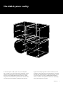
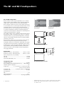
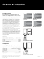
The Q-Series
Contents
The d&b System reality.......................................................... 3
The Q-Series................................................................................ 4
The Q-Series product photographs .................................. 5
The Q1 and Qi1 loudspeakers............................................. 6
The Q7 and Qi7 loudspeakers............................................. 7
The Q10 and Qi10 loudspeakers........................................ 8
The Q, Qi and QiCSA subwoofers....................................... 9
The Q1 rigging system.......................................................... 10
The Q1 rigging examples..................................................... 11
The Q7/Q10 mounting accessories.................................. 12
The Q7/Q10 mounting examples..................................... 13
The Qi rigging system............................................................ 14
The Qi1 rigging examples................................................... 15
The Qi rigging system............................................................ 16
The Qi7/Qi10 rigging examples....................................... 16
The Qi7/Qi10 mounting and rigging
accessories and examples................................................... 17
The d&b ArrayCalc calculator............................................ 18
The D6 and D12 amplifiers.................................................. 20
The D6 and D12 amplifier data......................................... 21
The operation with D6 and D12 amplifiers.................. 22
The Q-Series frequency responses................................... 23
The Q-Series configuration examples............................. 24
The Qi loudspeakers Weather Resistant and
Special Colour options.......................................................... 29
The D6 and D12 amplifiers installation.......................... 30
The D6 and D12 amplifiers
power consumption and power loss............................... 31
The d&b Remote network.................................................... 32
The d&b Remote software................................................... 33
The Q-Series product overview......................................... 34
2
d&b Q-Series
The d&b System reality
As the name implies a d&b system is not just a loudspeaker.
Nor is it merely a sum of the components: loudspeakers, control
electronics, mechanical accessories and remote control. Right
from the outset the d&b audiotechnik approach was to build
integrated sound reinforcement systems that were more than the
sum of their parts. Each element is tightly specified, precisely
aligned and carefully integrated to achieve maximum possible
performance, along with neutral sound characteristics. At the same
time d&b offers integrated training, technical information, expert
service and support, as well as a knowledgeable distribution
network, so that the same optimal acoustic result is achieved by
every system anywhere, at any time.
d&b Q-Series
3
The Q-Series
The Q-Series embodies the d&b holistic approach to sound
reinforcement solutions: integrating loudspeakers, electronics,
mechanical deployment assemblies, remote control functions and
setup design tools for precise calculation of array performance.
Control of dispersion behaviour is a particular fixation at d&b,
while at the same time keeping the size and weight of systems to
an absolute minimum. The Q-Series maintains the ”d&b specific”
combination of a neutral, intelligible sound character that is
clear and transparent even at high sound pressure levels
providing the engineer with an efficient, effortless tool and a
neutral platform.
The Q-Series loudspeakers are the perfect option for speech and
music in many theatre and presentation situations, live television
and orchestral shows, situations where multiple open microphones
are used and considerable gain before feedback is an absolute
requirement. The transparency, bandwidth, high power and
headroom capabilities, also make them ideal for any type of
amplified music. The scope of applications is intentionally broad,
ranging from single loudspeakers right through to larger multiple
cabinet arrays. To this end a variety of technologies are used:
conventional rotatable CD horns, dipolar driver arrangements,
low compression vented designs with high excursion drivers and
toroidal wave shaping devices, all integrated using line array
principals.
The Q and Qi loudspeakers are designed for mobile and
installed applications respectively, the Qi versions differing
only in cabinet construction and mounting hardware. The Q
loudspeakers are designed for a wide range of small to medium
scale applications with a clear perspective to provide mobile,
flexible, configurable array solutions to the most arduous sound
reinforcement situations. The d&b ArrayCalc calculator predicts
the performance of arrays, enabling simple and accurate system
planning. The Qi loudspeakers are intended for permanently
installed performance spaces where the specification is rider
driven by the artist or mix engineer’s preferences. Both the
Qi cabinets and mounting hardware can be properly colour
matched to interior designs, are mechanically adapted for
installation use and can provide protection in climatically hostile
environments.
The 2-way passively crossed over Q1/Qi1, Q7/Qi7 and
Q10/Qi10 loudspeaker cabinets sharing the same physical size,
shape, rigging and driver compliment. The highest degree of
constant directivity is maintained using a large frequency overlap
through the crossover range, while the recessed dipolar positioning
of the two 10” low frequency drivers mechanically time aligns
these with the 1.3” exit HF driver. The Q1/Qi1 HF drivers are
4
d&b Q-Series
fitted with a toroidal wave shaping device, which have a 75° (h)
and 75° x 15° (h x v) dispersion pattern respectively, the resulting
curved coherent wave front allows vertical arrays of multiple
cabinets to be constructed. The Q7/Qi7 and Q10/Qi10
loudspeakers also use a 1.3” HF driver fitted to rotatable 75° x 40°
and 110° x 40° (h x v) constant directivity horns respectively
allowing them to be configured for use both vertically or
horizontally. When deployed upright, the Q7/Qi7 and Q10/Qi10
are accurate stand-alone full range loudspeakers with vertical
directivity control extending approximately one octave below
similarly sized biaxial loudspeakers. Their horizontal coverage
angles can also be used to fulfil near field or infill functions
for Q1/Qi1 arrays, either flown, stacked or ground supported.
When deployed horizontally with the horn rotated, the horizontal
dispersion control of the Q7/Qi7 is maintained down to
approximately 400 Hz. This performance can be used very
effectively in critical positions close to open microphones and
also allows the Q7/Qi7 loudspeakers to be combined as the
near field element in Q1/Qi1 columns.
The Q, Qi and QiCSA subwoofers complete the Series’ sharing
the same width as the other loudspeakers and having compatible
flying fittings that enable their use in columns with Q and Qi
loudspeakers respectively. The Q, Qi and QiCSA-SUB cabinets are
bass-reflex designs with an 18” high excursion driver. Multiples
of three Q-SUBs or two Qi-SUBs and one QiCSA-SUB can be
combined to produce Cardioid Subwoofer Arrays (CSA) when
driven by the D6 or D12 amplifier. The D12 amplifier incorporates
d&b SenseDrive technology for accurate control of LF driver
membranes.
The d&b D6 and D12 dual channel amplifiers realize the
complete system. They provide two different power ranges,
incorporate d&b loudspeaker specific configuration information
and have analog and digital signal inputs and links. These devices
are specially designed and manufactured by d&b utilizing Digital
Signal Processing and include switchable functions for precisely
tailoring system response for a wide variety of applications. A user
definable 4-band parametric equalizer and a delay capability is
provided in every amplifier channel to reduce the need for external
processing devices. The D12 amplifier additionally offers a
2-Way Active mode and a MIX TOP/SUB output configuration,
output connector options as well as d&b SenseDrive.
The D6 and D12 amplifiers have d&b Remote network
interfaces enabling control and monitoring of a large number of
system functions and extensive system integration capabilities.
d&b Load monitoring and System check are also incorporated to
remotely monitor loudspeaker driver status.
The Q-Series
Q1 loudspeaker
Qi1 loudspeaker
D6 amplifier
Q7, Q10 loudspeaker
Q subwoofer
Qi7, Qi10 loudspeaker
Qi, QiCSA subwoofer
D12 amplifier
d&b Q-Series
5
The Q1 and Qi1 loudspeakers
90
80
70
60
50
40
30
20
10
0
–10
–20
–30
–40
–50
–60
–70
–80
–90
500
1k
2k
4k
8k
16k
250
500
1k
204.5 [8.05"]
308 [12.13"]
125
2k
4k
8k
16k
Q1 and Qi1 vertical dispersion
characteristics2
410 [16.14"]
580 [22.83"]
15°
308 [12.13"]
204.5 [8.05"]
Q1 cabinet dimensions in mm (inch)
154 [6.06"]
60 [2.36"]
410 [16.14"]
310 [12.20"]
Loudspeaker data
Nominal impedance...............................................................8 ohms
Power handling capacity (RMS/peak 10 ms)..........400/1600 W
Nominal dispersion angle (h)..................................................... 75°
Components......................2 x 10” driver /1.3” compression driver
................................................................. passive crossover network
Connections Q1.......................2 x EP5, 2 x NL4 or 2 x NLT4 F/M
Connections Qi1.................................................................. 2 x NL4
Pin assignments...................................................................................
EP5...............................................................................................1/2
NL4 and NLT4 F/M................................................................ 1+/1–
Weight Q1/Qi1............................................. 22/21 kg (49/46 lb)
Qi1 cabinet dimensions in mm (inch)
1
d&b Q-Series
250
580 [22.83"]
System data
Frequency response (–5 dB standard)................... 60 Hz - 17 kHz
Frequency response (–5 dB CUT mode).............. 100 Hz - 17 kHz
Max. sound pressure (1 m, free field)1.............................................
with D6................................................................................... 135 dB
with D12................................................................................ 139 dB
Input level (100 dB SPL/1 m)............................................. –18 dBu
6
125
Q1 and Qi1 horizontal dispersion
characteristics2
90
80
70
60
50
40
30
20
10
0
–10
–20
–30
–40
–50
–60
–70
–80
–90
15˚
Q1 and Qi1 loudspeakers
The Q1 and Qi1 are line array loudspeakers for use in vertical
columns. The Qi1 is the installation version of the Q1 loudspeaker,
it differs only in cabinet construction and mounting hardware.
The Q1 and Qi1 cabinets are passive 2-way designs that houses
2 x 10” LF drivers and a 1.3” HF compression driver with a toroidal
waveshaping device to achieve a 75° horizontal dispersion
characteristic. The two 10” neodymium LF drivers are positioned
in a dipolar arrangement providing an exceptional dispersion
control even at lower frequencies, with the 75° nominal dispersion
angle being maintained down to 400 Hz.
Q1 and Qi1 cabinets can be combined with the respective Q and
Qi subwoofer systems: in mixed line array setups, as a separate
subwoofer column or in ground stacked applications. For further
extension of bandwidth and headroom ground stacked J-INFRA
subwoofers can be used.
The Q1 and Qi1 cabinets are constructed from marine plywood
and have an impact resistant paint finish. The front of the
loudspeaker cabinets are covered with a replaceable acoustically
transparent foam and protected by a rigid metal grill. Four M10
threaded inserts on each side panel of the Qi1 cabinet enclosure
are provided for attaching installation hardware whilst the Q1
cabinet incorporates a pair of handles and has integrated line
array rigging hardware.
2
Broadband measurement, pink noise, crest factor 4, peak measurement, linear weighting
Dispersion angle vs frequency plotted using lines of equal sound pressure (isobars)
at –6 dB and –12 dB
The Q7 and Qi7 loudspeakers
250
500
1k
2k
4k
8k
16k
125
250
500
1k
2k
4k
8k
16k
Q7 and Qi7 horizontal dispersion
characteristics2
Q7 and Qi7 vertical dispersion
characteristics2
90
80
70
60
50
40
30
20
10
0
–10
–20
–30
–40
–50
–60
–70
–80
–90
90
80
70
60
50
40
30
20
10
0
–10
–20
–30
–40
–50
–60
–70
–80
–90
125
250
500
1k
2k
4k
8k
16k
125
250
500
1k
2k
4k
8k
16k
Q7 and Qi7 vertical dispersion
characteristics/rotated horn2
580 [22.83"]
Q7 and Qi7 horizontal dispersion
characteristics/rotated horn2
308 [12.13"]
410 [16.14"]
204.5 [8.05"]
15˚
Q7 cabinet dimensions in mm (inch)
580 [22.83"]
Loudspeaker data
Nominal impedance...............................................................8 ohms
Power handling capacity (RMS/peak 10 ms)..........400/1600 W
Nominal dispersion angle (h x v).................................... 75° x 40°
Components......................2 x 10” driver /1.3” compression driver
................................................................. passive crossover network
Connections Q7.......................2 x EP5, 2 x NL4 or 2 x NLT4 F/M
Connections Qi7.................................................................. 2 x NL4
Pin assignments...................................................................................
EP5...............................................................................................1/2
NL4 and NLT4 F/M................................................................ 1+/1–
Weight Q7/Qi7............................................. 22/21 kg (49/46 lb)
125
90
80
70
60
50
40
30
20
10
0
–10
–20
–30
–40
–50
–60
–70
–80
–90
308 [12.13"]
410 [16.14"]
204.5 [8.05"]
310 [12.2"]
System data
Frequency response (–5 dB standard)................... 60 Hz - 17 kHz
Frequency response (–5 dB CUT mode).............. 100 Hz - 17 kHz
Max. sound pressure (1 m, free field)1.............................................
with D6................................................................................... 134 dB
with D12................................................................................ 138 dB
Input level (100 dB SPL /1 m)............................................ –17 dBu
90
80
70
60
50
40
30
20
10
0
–10
–20
–30
–40
–50
–60
–70
–80
–90
154 [6.06"]
60 [2.36"]
Q7 and Qi7 loudspeakers
The Q7 and Qi7 are full range loudspeakers. The Qi7 is the
installation version of the Q7 loudspeaker, it differs only in cabinet
construction and mounting hardware.
The Q7 and Qi7 are 75° x 40° passive 2-way cabinets housing
2 x 10” LF drivers and a 1.3” HF compression driver with a
rotatable constant directivity horn and a passive crossover
network. The two 10” neodymium LF drivers are positioned in a
dipolar arrangement providing exceptional vertical dispersion
control with the 40° nominal angle being maintained down to
400 Hz. The precisely controlled 75° horizontal dispersion
performance provides the ideal pattern for many medium throw
requirements. The horn can be rotated by 90°.
The Q7 and Qi7 can be used as stand-alone full range systems
in combinations with other Q and Qi loudspeakers, ground
stacked or mounted on a high stand. Q7 and Qi7 cabinets can
also be combined in flown array systems.
The Q7 and Qi7 cabinets are constructed from marine plywood
and have an impact resistant paint finish. The front of the
loudspeaker cabinets are covered with a replaceable acoustically
transparent foam and protected by a rigid metal grill. Four M10
threaded inserts on each side panel of the Qi7 cabinet enclosure
are provided for attaching installation hardware whilst the Q7
cabinet incorporates a pair of handles and has integrated line
array rigging hardware.
15˚
Qi7 cabinet dimensions in mm (inch)
1
2
Broadband measurement, pink noise, crest factor 4, peak measurement, linear weighting
Dispersion angle vs frequency plotted using lines of equal sound pressure (isobars)
at –6 dB and –12 dB
d&b Q-Series
7
The Q10 and Qi10 loudspeakers
Q10 and Qi10 loudspeakers
The Q10 and Qi10 are full range loudspeakers. The Qi10 is the
installation version of the Q10 loudspeaker, it differs only in cabinet
construction and mounting hardware.
The Q10 and Qi10 are 110° x 40° passive 2-way cabinets
housing 2 x 10” LF drivers and a 1.3” HF compression driver
with a rotatable constant directivity horn and a passive crossover
network. The two 10” neodymium LF drivers are positioned in a
dipolar arrangement providing exceptional vertical dispersion
control with the 40° nominal angle being maintained down to
400 Hz.
Q10 and Qi10 can be used as stand-alone full range systems,
in combinations with other Q and Qi cabinets ground stacked
or mounted on a high stand. The wide constant directivity
performance provides remarkable transparency when used in
close proximity to listeners. It is also ideally suited to ambient and
distributed sound reinforcement tasks. When used in the upright
configuration the Q10 and Qi10 have a very accurate 110°
horizontal constant directivity behaviour that is maintained down
to approximately 800 Hz.
The Q10 and Qi10 cabinets are constructed from marine plywood
and have an impact resistant paint finish. The front of the
loudspeaker cabinets are covered with a replaceable acoustically
transparent foam and protected by a rigid metal grill. Four M10
threaded inserts on each side panel of the Qi10 cabinet enclosure
are provided for attaching installation hardware whilst the Q10
cabinet incorporates a pair of handles and has integrated rigging
hardware.
90
80
70
60
50
40
30
20
10
0
–10
–20
–30
–40
–50
–60
–70
–80
–90
90
80
70
60
50
40
30
20
10
0
–10
–20
–30
–40
–50
–60
–70
–80
–90
250
500
1k
2k
4k
8k
16k
125
250
500
1k
2k
4k
125
250
500
1k
2k
4k
8k
16k
Q10 and Qi10 vertical dispersion
characteristics2
8k
16k
90
80
70
60
50
40
30
20
10
0
–10
–20
–30
–40
–50
–60
–70
–80
–90
125
250
500
1k
2k
4k
8k
16k
Q10 and Qi10 vertical
dispersion characteristics/
rotated horn2
580 [22.83"]
Q10 and Qi10 horizontal
dispersion characteristics/
rotated horn2
308 [12.13"]
410 [16.14"]
204.5 [8.05"]
15˚
580 [22.83"]
Q10 cabinet dimensions in mm (inch)
Loudspeaker data
Nominal impedance...............................................................8 ohms
Power handling capacity (RMS/peak 10 ms)......... 400 /1600 W
Nominal dispersion angle (h x v).................................. 110° x 40°
Components....................... 2 x 10” driver/1.3” compression driver
................................................................. passive crossover network
Connections Q10.....................2 x EP5, 2 x NL4 or 2 x NLT4 F/M
Connections Qi10................................................................ 2 x NL4
Pin assignments...................................................................................
EP5...............................................................................................1/2
NL4 and NLT4 F/M................................................................ 1+/1–
Weight Q10/Qi10........................................ 22/21 kg (49/46 lb)
308 [12.13"]
410 [16.14"]
310 [12.2"]
154 [6.06"]
60 [2.36"]
204.5 [8.05"]
15˚
Qi10 cabinet dimensions in mm (inch)
1
d&b Q-Series
125
Q10 and Qi10 horizontal
dispersion characteristics2
System data
Frequency response (–5 dB standard)................... 60 Hz - 17 kHz
Frequency response (–5 dB CUT mode).............. 100 Hz - 17 kHz
Max. sound pressure (1 m, free field)1.............................................
with D6................................................................................... 133 dB
with D12................................................................................ 137 dB
Input level (100 dB SPL /1 m)............................................ –17 dBu
8
90
80
70
60
50
40
30
20
10
0
–10
–20
–30
–40
–50
–60
–70
–80
–90
2
Broadband measurement, pink noise, crest factor 4, peak measurement, linear weighting
Dispersion angle vs frequency plotted using lines of equal sound pressure (isobars)
at –6 dB and –12 dB
668 [26.30"]
773 [30.42"]
Q-SUB cabinet dimensions in mm (inch)
377 [14.84"]
580 [22.83"]
124 [4.88"]
310 [12.20"]
60 [2.36"]
System data
Frequency response (–5 dB standard)...................40 Hz - 130 Hz
Frequency response (–5 dB 100 Hz mode)..........40 Hz - 100 Hz
Max. sound pressure (1 m, free field)1.............................................
with D6................................................................................... 129 dB
with D12................................................................................ 133 dB
580 [22.83"]
493 [19.40"]
Q, Qi and QiCSA subwoofers
Q, Qi and QiCSA-SUB are the dedicated subwoofers for the
Q and Qi loudspeakers respectively and can be used to
supplement the top cabinets in various combinations, either flown
or ground stacked. The Qi and QiCSA are the installation versions
of the Q subwoofer, they differ only in cabinet construction and
mounting hardware. They are actively driven bass-reflex designs
housing a long excursion 18" driver.
The subwoofers can be combined with the respective Q and Qi
loadspeakers in line arrays, as a separate column or in ground
stacked applications where the subwoofers also mechanically
support the top loudspeakers.
The Q, Qi and QiCSA subwoofer cabinets are constructed from
marine plywood and have an impact resistant paint finish. The
front of the subwoofer cabinets are covered with a replaceable
acoustically transparent foam and protected by a rigid metal grill.
The QiCSA-SUB cabinet has foams fitted to both the front and
rear sides of the cabinet, the grill facing backwards is fitted with
a single NL4 connector (see page 15). Four M10 threaded
inserts on each side panel of the Qi and QiCSA-SUB enclosure
are provided for attaching installation hardware whilst the Q-SUB
cabinet incorporates a pair of handles, an M20 threaded flange
in the top panel and has integrated line array rigging hardware.
493 [19.40"]
The Q, Qi and QiCSA subwoofers
668 [26.30"]
Loudspeaker data
Nominal impedance...............................................................8 ohms
Power handling capacity (RMS/peak 10 ms)..........400/1600 W
Components.......................................................................18” driver
Connections Q-SUB..................2 x EP5, 2 x NL4 or 2 x NLT4 F/M
Connections Qi/QiCSA-SUB............................... 2 x NL4/1 x NL4
Pin assignments...................................................................................
EP5......................................................................3/4, SenseDrive: 5
NL4 and NLT4 F/M................................................................ 2+/2–
Weight Q/Qi/QiCSA...................42/37/40 kg (92.6/81/88 lb)
Qi and QiCSA-SUB cabinet dimensions in mm (inch)
1
Broadband measurement, pink noise, crest factor 4, peak measurement, linear weighting
d&b Q-Series
9
The Q1 rigging system
Safety approval
d&b loudspeakers and accessories are designed for set up and
use within situations requiring compliance with the provisions and
directives of BGV C1 Rule for the Prevention of Accidents.
Z5154 Q Rigging set:
Z5151
Q Splay link
Z5159
Q Flying frame
WLL: 480 kg/1058 lb
or twenty Q1 loudspeakers
Z5147
Rota clamp
WLL: 500 kg/1100 lb;
for a tube diameter up to
51 mm/2”
10 d&b Q-Series
Z5155
Q Hoist connector chain
WLL: 480 kg/1058 lb
or twenty Q1 loudspeakers
Z5152
Q Front link
Z5153
Locking pins 8 mm
Z5160
Q Load adapter
WLL: 480 kg/1058 lb
or twenty Q1 loudspeakers;
aiming of a column by 1/1,
1/2 or 1/4 detents
Z5156
Q Flying adapter
For three Q1 loudspeakers
maximum
E6507
1t Shackle
Z5048
Flying pin 10 mm
The Q1 rigging examples
With a 15° vertical HF dispersion per cabinet, the Q1 can be
used to construct vertical columns that produce a curved coherent
wave front. The mechanical and acoustical design of the cabinet
enables vertical splay angles to be set between 0° and 14°. Q1
cabinets can therefore be used in vertical configurations starting
from two cabinets with a 15° to 30° dispersion, up to twenty
cabinets with a fully user and venue defined vertical profile.
For further information please refer to the TI 385 d&b Line array
design and Q-Series Rigging manual, which are available for
download at www.dbaudio.com.
Q1 line array with
Z5159 Q Flying frame
Z5154 Q Rigging set
Z5155 Q Hoist connector chain
E6507 1t Shackles
Q1/Q-SUB ground stack with
Z5154 Q Rigging set
Q1 ground stack with
Z5159 Q Flying frame
Z5154 Q Rigging set
Q1 array with
Z5156 Q Flying adapter
Z5154 Q Rigging set
Z5147 Rota clamp
Q1/Q-SUB array with
Z5159 Q Flying frame
Z5154 Q Rigging set
Z5147 Rota clamp
Z5160 Q Load adapter
d&b Q-Series 11
The Q7/Q10 mounting accessories
Safety approval
d&b loudspeakers and accessories are designed for set up and
use within situations requiring compliance with the provisions and
directives of BGV C1 Rule for the Prevention of Accidents.
Z5154 Q Rigging set:
Z5151
Q Splay link
Z5152
Q Front link
Z5153
Locking pins 8 mm
Z5161
Q Flying bracket
Z5150
Q Swivel bracket
Z5175
Qi Horizontal bracket
Z5025
Flying adapter 03
Z5156
Q Flying adapter
For three Q7 loudspeakers
maximum
Z5048
Flying pin 10 mm
Z5015
TV spigot 02
Z5010
TV spigot with
fixing plate
Z5012
Pipe clamp for TV spigot
WLL: 100 kg/220 lb;
for a tube diameter up to
70 mm/2.75”
Z5147
Rota clamp
WLL: 500 kg/1100 lb;
for a tube diameter up to
51 mm/2”
Z5024
Loudspeaker
stand adapter
E6507
1t Shackle
Q9032
Safety eyebolt M10
12 d&b Q-Series
Z5020
Flying adapter 02
The Q7/Q10 mounting examples
Q7/Q10 with
Z5161 Q Flying bracket
Z5010 TV spigot with fixing plate
Z5012 Pipe clamp for TV spigot
Q7/Q10 with
Z5161 Q Flying bracket
Z5024 Loudspeaker
stand adapter
Q7/Q10 with
Z5150 Q Swivel bracket
Z5010 TV spigot with fixing plate
Z5012 Pipe clamp for TV spigot
Q7/Q10 with
Z5020 Flying adapter 02
Z5015 TV spigot 02
Q7/Q10 with
Z5156 Q Flying adapter
Z5147 Rota clamp
Q7/Q10 with
Z5048 Flying pins 10 mm
Q7/Q10 with
Z5175 Qi Horizontal bracket
Z5010 TV spigot with fixing plate
Z5012 Pipe clamp for TV spigot
Q7/Q10 and Q-SUB with
Z5161 Q Flying bracket
Z5013 Loudspeaker stand
winder M20
d&b Q-Series 13
The Qi rigging system
Safety approval
d&b loudspeakers and accessories are designed for set up and
use within situations requiring compliance with the provisions
and directives of BGV C1 Rule for the Prevention of Accidents.
Z5145
Ci/Qi Mounting frame
WLL: 240 kg/530 lb
e.g. nine Q loudspeakers
Z5170
Qi Mounting adapter
Z5171
Qi Mounting plate
Z5147
Rota clamp
WLL: 500 kg/1100 lb;
for a tube diameter up to
51 mm/2”
Z5160
Q Load adapter
WLL: 480 kg/1058 lb
or 20 Qi1 loudspeakers;
aiming of a column by 1/1,
1/2 or 1/4 detents
14 d&b Q-Series
Z5172
Qi-SUB
Mounting plate
The Qi1 rigging examples
With a 15° vertical HF dispersion per cabinet, the Qi1 can be
used to construct vertical columns that produce a curved coherent
wave front. The mechanical and acoustical design of the cabinet
enables vertical splay angles to be set between 0° and 14°. Qi1
cabinets can therefore be used in vertical configurations starting
from two cabinets with a 15° to 30° dispersion, up to nine
cabinets with a fully user and venue defined vertical profile. Qi
subwoofers can be integrated at any position within the array.
Three subwoofers can be mounted together in CSA mode, where
the centre QiCSA-SUB radiates to the back. For further information
please refer to the TI 385 d&b Line array design, which is
available for download at www.dbaudio.com.
Qi-SUB/QiCSA-SUB
Cardioid Subwoofer Array
front view
Qi-SUB/QiCSA-SUB
Cardioid Subwoofer Array
back view
Z5170
Z5172
Z5171
Flown Qi1/Qi-SUB array with
Z5145 Ci/Qi Mounting frame
Z5160 Q Load adapter
Z5147 Rota clamp
Z5170 Qi Mounting adapter
Z5171 Qi Mounting plate
Z5172 Qi-SUB Mounting plate
Qi rigging system
d&b Q-Series 15
The Qi rigging system
The Qi7/Qi10 rigging examples
Safety approval
d&b loudspeakers and accessories are designed for set up and
use within situations requiring compliance with the provisions
and directives of BGV C1 Rule for the Prevention of Accidents.
Z5170
Qi Mounting adapter
Z5145
Ci/Qi Mounting frame
WLL: 240 kg/530 lb
Z5147
Rota clamp
WLL: 500 kg/1100 lb;
for a tube diameter up to
51 mm/2”
Z5171
Qi Mounting plate
Z5172
Qi-SUB
Mounting plate
Z5160
Q Load adapter
WLL: 480 kg/1058 lb;
aiming of a column by 1/1,
1/2 or 1/4 detents
Z5170
Z5171
Flown Qi7/Qi10 array with
Z5145 Ci/Qi Mounting frame
Z5160 Q Load adapter
Z5147 Rota clamp
Z5170 Qi Mounting adapter
Z5171 Qi Mounting plate
16 d&b Q-Series
The Qi7/Qi10 mounting and rigging
accessories and examples
Safety approval
d&b loudspeakers and accessories are designed for set up and
use within situations requiring compliance with the provisions
and directives of BGV C1 Rule for the Prevention of Accidents.
Z5161
Q Flying bracket
Z5044
MAX Bracket
connector
Z5175
Qi Horizontal bracket
Z5053
Ci60/Ci90 Bracket
connector
Qi7/Qi10 with
Z5161 Q Flying bracket
Z5010 TV spigot with fixing plate
Z5012 Pipe clamp for TV spigot
Z5015
TV spigot 02
Z5020
Flying adapter 02
Z5010
TV spigot with
fixing plate
Qi7/Qi10 with
Z5175 Qi Horizontal bracket
Z5010 TV spigot with fixing plate
Z5012 Pipe clamp for TV spigot
Z5025
Flying adapter 03
Z5012
Pipe clamp for TV spigot
WLL: 100 kg/220 lb;
for a tube diameter up to
70 mm/2.75”
Qi7/Qi10 horizontal array with
Z5175 Qi Horizontal bracket
Z5044 MAX Bracket connector
Z5054
Ci60/Ci90
Flying adapter
Z5024
Loudspeaker
stand adapter
E6507
1t Shackle
Qi7/Qi10 vertical array with
Z5054 Ci60/Ci90 Flying adapter
Z5175 Qi Horizontal bracket
Z5053 Ci60/Ci90 Bracket connector
d&b Q-Series 17
The d&b ArrayCalc calculator
For both acoustic and safety reasons d&b line arrays must be
designed using the d&b ArrayCalc simulation tool. It is available
as a native stand-alone application for both Microsoft Windows1
(XP or higher) and Mac OS X2 (10.4.10 or higher) operating
systems.
ArrayCalc is the system engineer's comprehensive toolbox for all
tasks regarding acoustic design, performance prediction,
alignment, rigging and safety parameters of the d&b line array
systems and subwoofer arrays. In combination with the d&b
Remote network, this can significantly reduce setup and tuning time
in mobile applications, and allows for precise initial simulations
in the planning of installations. EASE and DXF data export
capabilities make for easy data transfer.
The program allows the user to define up to five three-dimensional
listening planes to quickly create a representation of the
audience areas in a given venue, including balconies, side
stalls and in-the-round scenarios. Special functions assist in
obtaining the proper dimensions with laser distance finders and
inclinometers.
Additionally, up to two acoustic obstacles representing for
example video cubes, which will obstruct the sound propagation,
can be added to the model. Up to fourteen flown arrays or
subwoofer columns can be defined in a project file as single
hangs or in pairs, as well as a ground stacked subwoofer array
consisting of up to twenty five stacks. They can be freely positioned
according to their intended application, for example as main
hang, outfill, delay line etc. Position, orientation, coverage and
aiming are displayed in top and side views. For every array,
achievable RMS level over distance is calculated with high
resolution in real time, for either band-limited or broadband input
signals. The comprehensive simulation precisely models the
actual performance of the system, taking into account input level,
all system configuration options (such as CUT, CPL, HFC or
INFRA), limiter activity and air absorption. Acoustic shadowing,
whether by obstacles (if defined) or a balcony overhang is also
calculated. The load status of all rigging components is also
constantly monitored and displayed to determine whether a
given array is within the load tolerance.
Subwoofer array design is assisted by coverage and polar plot
prediction. A specialized algorithm allows the user to specify
subwoofer positions and a coverage angle, which is then converted
into appropriate delay times that result in the desired dispersion.
The program allows the simulation of different arrays to be
delayed to one another as well as showing arrival times and SPL
18 d&b Q-Series
Room Settings
Arrays
Sub Array
The d&b ArrayCalc calculator
at a freely definable reference point on one of the audience
areas.
For alignment of the flown system with the ground stacked bass
array, the phase response of both the bass array and a selectable
flown array is calculated at a definable reference point. Both
simulations reflect changes in delay time to the single arrays in
real time, greatly obviating the need for time consuming acoustic
measurements to that end.
The level distribution resulting from the interaction of all active
arrays can be mapped onto the previously defined audience
areas in a three-dimensional view which can also be zoomed,
rotated and exported as a graphics file. Up to four diffferent
configurations and their mappings can be temporarily stored for
comparison.
A comprehensive rigging plot with all necessary coordinates,
dimensions and weights is automatically generated for export
and printing, as well as a parts list detailing all the loudspeakers
and rigging components required.
Using the R1 export function, a project file for the R1 remote
control software is generated containing the amplifiers (devices)
and all groups and control elements to operate the system
simulated in ArrayCalc. At the same time it saves the respective
amplifier settings in an R1 control settings file for later retrieval.
This workflow sequence removes the need to manually transfer
configuration information from one software to the other.
Further information and useful guidelines are provided in the
TI 385 d&b Line array design, which is available for download
at www.dbaudio.com.
Alignment
3D Plot
Rigging Plot
1
Microsoft Windows is a registered trademark or trademark of Microsoft Corporation in the United States and/or other countries
2 Mac OS is a trademark of Apple Inc., registered in the U.S. and other countries
d&b Q-Series 19
The D6 and D12 amplifiers
The D6 and D12 are dual channel amplifiers developed and
manufactured by d&b utilizing Digital Signal Processing (DSP) to
incorporate loudspeaker specific configuration information and
functions. These are designed for use with d&b loudspeakers,
have both digital and analog signal inputs as well as link outputs,
remote control and monitoring capabilities and switch mode power
supplies. The level control incorporates a digital rotary encoder
enabling selection of all operating modes in conjunction with a
Liquid Crystal Display (LCD).
Loudspeaker specific configurations for current d&b loudspeakers
and a linear mode are contained within them, the exception
being that the D6 does not include 2-Way Active, V-Series and
B2-SUB configurations.
The digital elements of the D6 and D12 are specified and
constructed to achieve the best possible audio performance while
maintaining a very low latency of 0.3 msec. The Digital Signal
Processing is used to provide the loudspeaker specific configurations,
sophisticated protection circuits modelling thermal and mechanical
driver behaviour, and switch functions.
User definable equalization and delay functions are incorporated
in each channel of the amplifiers and can be used for applications
such as front fills or under balcony delays without the need for
external processors. The signal delay capability allows delay
settings of up to 340 msec. (= 100 m /328 ft) to be applied
independently to each channel as can the 4-band parametric
equalizer, providing optional Boost /Cut or Notch filtering. A
signal generator offering pink noise or sine wave program is also
incorporated for test and alignment purposes. Every unit can be
given a unique Device Name to simplify identification and a
password protected LOCK function is also incorporated to prevent
unauthorized changes.
The D6 and D12 amplifiers also detect incoming Pilot signals at
its input (Input monitoring) and can use Load monitoring and
System check functions to determine the status of the loudspeaker
impedance. d&b System check is designed to verify that the
system performs within a predefined condition and can be used
to report the system condition after a show.
D6
d&b Load monitoring, on the other hand, enables automatic and
continuous impedance monitoring and along with Input monitoring
is designed for incorporation within applications specified to the
requirements stated in the International Standard IEC 60849
‘Sound Systems for Emergency Purposes’. Both can determine the
status of an LF or HF driver in systems with multiple elements,
even if these are crossed over passively.
The D6 utilizes a switch mode power supply with PFC suitable for
mains supply voltages 100 V/115 V/200 V/230 V, 50 - 60 Hz
whilst the D12 utilizes an autosensing switch mode power supply
for mains voltages 115/230 V, 50 - 60 Hz (optional 100/200 V).
Both power supplies have overvoltage protection and each
amplifier has a temperature and signal controlled fan to cool the
internal assemblies.
The 2 RU lightweight D6 is specifically designed to deliver medium
power into low impedance loads between 4 and 16 ohms. The
3 RU D12 is specifically designed to produce high power into
low impedance loads, typically those between 4 and 16 ohms.
Due to differences in impedance response against frequency, the
maximum number of cabinets driven by each D12 channel varies
depending on the loudspeaker type.
Apart from selectable output configurations for dual channel, Mix
TOP/SUB and 2-Way Active mode, the D12 also provides d&b
SenseDrive for use with the LF drivers in d&b active loudspeakers
and subwoofers.
Both amplifiers house an I/O panel containing: analog signal
inputs with link outputs for each channel, an AES/EBU digital
input with a link output and NL4 loudspeaker outputs. The D12
I/O panel additionally offers the options of EP5 or NL8
loudspeaker outputs. The two RJ 45 REMOTE sockets at the rear
of the D6 and the D12 amplifiers integrate them into the d&b
Remote network via CAN-Bus, enabling remote control and/or
monitoring.
A USB-B (D6) or a SUB-D9 (D12) SERVICE interface is provided
to enable future firmware updates containing new loudspeaker
configurations or additional functions to be loaded to the units.
CH A
MAINS SUPPLY
VOLTAGE SEE LABEL
~ 50/60 Hz, 1000 W
DIGITAL
OUT
A
D6 rear view
20 d&b Q-Series
OUT
B
REMOTE
SERVICE
AES/EBU
ANALOG
CH B
D12 rear view
The D6 and D12 amplifier data
D6 Display
ISP, GR, OVL A /B........................................................LED indicators
Liquid Crystal Display (LCD).........Graphic display/120 x 32 Pixel
D12 Display
ISP, GR, OVL A /B.......................................................LED indicators
Liquid Crystal Display (LCD).........Graphic display /120 x 32 Pixel
D6 Controls
POWER, MUTE /LEVEL..................................Switch, rotary encoder
Function switches..................................Loudspeaker specific circuits
4-band equalizer.............................................Optional PEQ /Notch
Delay setting........................0.3 - 340 msec. with 0.1 msec. detents
Configurations..............Current d&b loudspeakers and linear mode
......................................except 2-Way Active, V-Series and B2-SUB
Frequency generator....................................Pink noise or Sine wave
D12 Controls
POWER, MUTE /LEVEL..................................Switch, rotary encoder
Function switches..................................Loudspeaker specific circuits
4-band equalizer.............................................Optional PEQ /Notch
Delay setting........................0.3 - 340 msec. with 0.1 msec. detents
Configurations..............Current d&b loudspeakers and linear mode
Frequency generator....................................Pink noise or Sine wave
D6 Connectors
INPUT /LINK ANALOG A /B......................3 pin XLR female /male1
INPUT /LINK DIGITAL AES /EBU................3 pin XLR female /male1
Sampling rate..........................................................48 kHz /96 kHz
OUT CHANNEL A /B..................................................................NL4
REMOTE................................................................2 x RJ 45 parallel
SERVICE..........................................................................USB Type B
D6 Protection circuits
Mains inrush current limiter..............................1.5 A RMS at 230 V
Loudspeaker switch on delay.....................................Approx. 2 sec.
Overvoltage protection.............................................Up to 400 VAC
D6 Data (linear setting with subsonic filter)
Rated output power (THD+N < 0.1%)..............................................
............................2 x 350 W into 8 ohms, both channels are driven
............................2 x 600 W into 4 ohms, both channels are driven
S /N ratio (unweighted, RMS)...........................................>110 dBr
D6 Digital Signal Processing
Sampling rate...............................96 kHz /27 Bit ADC /24 Bit DAC
Basic delay/latency analog input.....................................0.3 msec.
1
D12 Connectors
INPUT/LINK ANALOG A/B.......................3 pin XLR female /male1
INPUT/LINK DIGITAL AES/EBU................3 pin XLR female /male1
Sampling rate..........................................................48 kHz /96 kHz
OUT CHANNEL A/B................................Optional EP5 /NL4 /NL8
REMOTE................................................................2 x RJ 45 parallel
SERVICE....................................................................SUB-D9 female
D12 Protection circuits
Mains inrush current limiter..................................5 A RMS at 230 V
Loudspeaker switch on delay.....................................Approx. 2 sec.
Overvoltage protection.............................................Up to 400 VAC
D12 Data (linear setting with subsonic filter)
Rated output power (THD+N < 0.1%)..............................................
............................2 x 750 W into 8 ohms, both channels are driven
.........................2 x 1200 W into 4 ohms, both channels are driven
S/N ratio (unweighted, RMS)............................................>110 dBr
D12 Digital Signal Processing
Sampling rate................................96 kHz/27 Bit ADC/24 Bit DAC
Basic delay/latency analog input......................................0.3 msec.
D6 Power supply
Switch mode power supply for..........................................................
..................................................100 /115 /200 /230V, 50 - 60 Hz
Mains connector...........................................................PowerCon® 2
D12 Power supply
Autosensing switch mode power supply for......................................
.....................................................................115/230 V, 50 - 60 Hz
......................................................optional 100 /200 V, 50 - 60 Hz
Mains connector...........................................................PowerCon® 2
D6 Remote network
Remote network...................................................................CAN-Bus
D12 Remote network
Remote network...................................................................CAN-Bus
D6 Dimensions, weight
Height x width x depth........................2 RU x 19” x 353 mm /13.9”
Weight..........................................................................8 kg /17.6 lb
D12 Dimensions, weight
Height x width x depth........................3 RU x 19” x 353 mm /13.9”
Weight...........................................................................13 kg /29 lb
XLR pin assignment analog, inputs and links: 1 = GND, 2 = pos. signal, 3 = neg. signal XLR pin assignment digital, input and link: 1 = GND, 2 = signal, 3 = signal
2PowerCon® is a registered trademark of the Neutrik AG, Liechtenstein
d&b Q-Series 21
The operation with D6 and D12 amplifiers
Operation with D6 and D12
Q10
Qi10
frequency response when a unit is placed close to listeners in near
field or delay use. High Frequency Attenuation begins gradually
at 1 kHz, dropping by approximately 3 dB at 10 kHz. This roll
off mimics the decline in frequency response experienced when
listening to a system from a distance in a typically reverberant
room or auditorium.
Q-SUB
QiCSA
Qi-SUB
-SUB
Q1
Qi1
Q7
Qi7
Max. LS
per channel
2
2
2
2
2
Max. LS per
channel in special
applications1
3
3
3
3
3
CPL function
The CPL (Coupling) function compensates for coupling effects
between closely coupled cabinets by reducing the low and mid
frequency level. CPL begins gradually at 1 kHz, with maximum
attenuation below 400 Hz, providing a balanced frequency
response when cabinets are used in arrays of two or more. The
CPL function can be set in dB attenuation values between –9
and 0, or a positive CPL value which creates an adjustable low
frequency boost around 65 Hz (0 to +5 dB).
Maximum loudspeakers per D6 or D12 channel
D6 and D12 controller settings
Q1
Qi1
Q7
Qi7
CUT
x
x
x
HFC
x
x
x
x
x
HFA
CPL
x
Q10
Qi10
Q-SUB
QiCSA
Qi-SUB
-SUB
100 Hz mode
If the 100 Hz mode is selected, the upper operating frequency
of the system is reduced to 100 Hz. This setting allows the
subwoofer to supplement top cabinets in full range mode.
100 Hz
x
CSA
x
CSA mode
CSA (Cardioid Subwoofer Array) mode enables the combination
of three or multiples of three subwoofer cabinets into an array
that produces exceptional low frequency directivity control. The
centre cabinet in a column is physically pointed to the rear and
the CSA mode selected on the D6 or D12 channel that powers
this cabinet. The forward facing cabinets are driven with a D6
or D12 channel set in the standard mode. The resulting cardioid
behaviour of the array will significantly reduce the energy
radiated to the rear. For further information please refer to the
d&b TI 330 Cardioid Subwoofer Array, which is available for
download at www.dbaudio.com.
x
D6 and D12 controller settings for each loudspeaker
CUT mode
Set to CUT, the cabinet low frequency level is reduced and is
configured for use with d&b active subwoofers.
HFC mode
Selecting the HFC (High Frequency Compensation) mode
compensates for loss of high frequency energy due to absorption
in air when loudspeakers are used to cover far field listening
positions. HFC should be used selectively, only for those cabinets
covering distances larger than 50 m (160 ft). This enables the
correct sound balance between close and remote audience
areas, whilst all amplifiers driving the array can be fed with the
same signal.
d&b SenseDrive
The D12 incorporates d&b SenseDrive for accurate control of
LF drivers in d&b loudspeakers driven 2-Way Active or in d&b
subwoofers driven actively, resulting in an extremely precise bass
performance, even at high levels. SenseDrive is only available
using a D12 fitted with EP5 connectors and appropriate 5-wire
cabling. For further information please refer to the d&b TI 340
SenseDrive, which is available for download at www.dbaudio.com.
HFA mode
In HFA mode (High Frequency Attenuation), the HF response of
the system is rolled off. The HFA provides a natural, balanced
22 d&b Q-Series
1
In applications with low continuous levels and low ambient temperatures
The Q-Series frequency responses
10
10
5
5
0
0
-5
-5
-10
-10
-15
-15
-20
-20
-25
-25
-30
20
100
1k
Q1 and Qi1 standard and CUT (single cabinet)
10k
20k
-30
10
10
5
5
0
0
-5
-5
-10
-10
-15
-15
-20
-20
-25
-25
-30
20
100
1k
10k
20k
Q10 and Qi10 standard and CUT
-30
10
5
5
0
0
-5
-5
-10
-10
-15
-15
-20
-20
-25
-25
-30
20
100
Correction of HFC
100
1k
10k
20k
20
100
1k
10k
20k
20
100
1k
10k
20k
Q, Qi and QiCSA-SUB standard and 100 Hz
10
-30
20
Q7 and Qi7 standard and CUT
1k
10k
20k
Correction of HFA
d&b Q-Series 23
The Q-Series configuration examples
A small Q-Series line array configuration as shown on
the opposite page could consist of two D12 amplifiers, three
Q1/Qi1 loudspeakers, one Q7/Qi7 loudspeaker and four
Q-SUBs/Qi-SUBs. Three Q1s/Qi1s are driven by one D12 channel
and one Q7/Qi7 from the other, this total load is acceptable for
one D12. The Q7/Qi7 is suspended horizontally with a rotated
horn as a downfill and enlarges the vertical coverage in the
near field. Four Q-SUBs/Qi-SUBs are driven by the second D12
amplifier.
A medium sized Q-Series configuration as shown on
page 26 could consist of three D12 amplifiers and six Q1/Qi1
loudspeakers along with two subwoofer stacks comprising three
Q-SUBs/Qi-SUBs and one QiCSA-SUBs in CSA mode. Two
Q1/Qi1 loudspeakers are driven from one channel using three
in total of the D12 channels. The forward facing Q-SUBs/Qi-SUBs
are driven from two D12 channels set in the standard Q-SUB
configuration. The rear facing Q-SUBs/QiCSA-SUBs are powered
by the remaining D12 channel configured for Q-SUBs with the
CSA mode selected. In small or medium sized configurations
using music program material a one to one ratio of Q1/Qi1 to
Q-SUBs/Qi-SUBs is recommended.
A large sized Q-Series configuration as shown on page
27 could consist of eight D12 amplifiers, sixteen Q1/Qi1
loudspeakers and two Q7/Qi7 loudspeakers along with two
subwoofer stacks comprising twelve Q-SUBs or Qi-SUBs with the
two middle cabinets in CSA configuration and one J-INFRA. All
the Q1/Qi1 loudspeakers are driven by eight D12 channels,
two Q7/Qi7 loudspeakers driven by one D6 amplifier are used
to cover the near field. Eight forward facing Q-SUBs/Qi-SUBs
are driven by four D12 channels set in the standard Q-SUB
configuration, whilst the rear facing Q-SUBs/QiCSA-SUBs are
driven by two D12 channels configured for Q-SUBs with the CSA
mode selected. The frequency response below 40 Hz can be
significantly enriched by the use of a J-INFRA subwoofer driven
from one D12. As the horizontal constant directivity of a Q1/Qi1
column is maintained down to 400 Hz, two columns of Q1s/Qi1s
can be arrayed side by side to provide wider horizontal coverage.
A horizontal angle of 50° between two columns provides the
best compromise between level and frequency response. The two
Q7s/Qi7s are used to cover the near field providing sufficient
coverage and level.
For further information please refer to the TI 385 d&b Line array
design, which is available for download at www.dbaudio.com.
24 d&b Q-Series
Q10
Qi10
Laptop
or PC
running R1
R60
CAN-Bus
interface
CAN-Bus
Q-SUB
Qi-SUB
D6
Small basic configuration example
The Q-Series configuration examples
Q1
Qi1
Q1
Qi1
Q1
Qi1
Q7
Qi7
Q-SUB
Qi-SUB
Q-SUB
Qi-SUB
Q-SUB
Qi-SUB
Q-SUB
Qi-SUB
D12
Laptop
or PC
running R1
D12
R60
CAN-Bus
Small line array configuration example
CAN-Bus
interface
d&b Q-Series 25
The Q-Series configuration examples
Q1
Qi1
Q1
Qi1
Q1
Qi1
Q1
Qi1
Q1
Qi1
Q-SUB
Qi-SUB
Q1
Qi1
Q-SUB
Qi-SUB
Q1
Qi1
D12
Q1
Qi1
Laptop
or PC
running R1
Q-SUB
Qi-SUB
CAN-Bus
CAN-Bus
interface
R60
Small ground stacked configuration example
Q-SUB
Qi-SUB
Q-SUB
Qi-SUB
Q-SUB
Q-SUB
QiCSA-SUB
QiCSA-SUB
Q-SUB
Qi-SUB
Q-SUB
Qi-SUB
Laptop
or PC
running R1
D12
D12
R60
D12
CAN-Bus CAN-Bus
interface
Medium flown and ground stacked example
26 d&b Q-Series
The Q-Series configuration examples
Q1
Qi1
Q1
Qi1
Q1
Qi1
Q1
Qi1
Q1
Qi1
Q1
Qi1
Q1
Qi1
Q1
Qi1
Laptop
or PC
running R1
Q1
Qi1
Q1
Qi1
Q1
Qi1
R60
Q1
Qi1
CAN-Bus
interface
Q1
Qi1
CAN-Bus
Q1
Qi1
Q1
Qi1
Q-SUB
Qi-SUB
Q-SUB
Qi-SUB
Q-SUB
Qi-SUB
Q-SUB
Qi-SUB
Q-SUB
QiCSA-SUB
Q-SUB
Q1
Qi1
D12
D12
D12
D12
Q-SUB
QiCSA-SUB
Q-SUB
QiCSA-SUB
QiCSA-SUB
Q-SUB
Qi-SUB
Q-SUB
Qi-SUB
Q-SUB
Qi-SUB
Q-SUB
Qi-SUB
D12
D12
D12
D6
Q7
Qi7
Q7
Qi7
J-INFRA
D12
Large flown and ground stacked configuration example
d&b Q-Series 27
The Q-Series configuration examples
Q1
Qi1
Q1
Qi1
Q1
Qi1
Q1
Qi1
Q1
Qi1
Q7
Qi7
Q1
Qi1
Q10
Qi10
Laptop or PC
running R1
Q10
Qi10
Q10
Qi10
R60
CAN-Bus
interface
CAN-Bus
Q-SUB
Qi-SUB
Q-SUB
Qi-SUB
D6
Q-SUB
QiCSA-SUB
D6
D12
Q-SUB
QiCSA-SUB
D12
Q-SUB
Qi-SUB
D12
Q-SUB
Qi-SUB
Q1/Qi1 flown line arrays in left/right configuration with Q7/Qi7 and Q10/Qi10 centre cluster, Q10s/Qi10s as fills and ground stacked Q/Qi-SUBs
and QiCSA-SUBs
28 d&b Q-Series
The Qi loudspeakers Weather Resistant and
Special Colour options
The Weather Resistant and Special Colour options are only
available to order with the Qi version cabinets.
Weather Resistant (WR) option
The WR option enables operation of loudspeakers in changing
ambient conditions, however it is not intended to enable permanent,
unprotected operation of loudspeakers outdoors. Cabinets being
used outdoors even with the WR option should always be aimed
either horizontally or with a downward tilt. The QiCSA-SUB
should only be aimed horizontally. An additional cover should be
positioned over the loudspeakers.
Qi loudspeakers with the Weather Resistant option are supplied
with a fixed cable. Cable type H-07-RN-F 2 x 2.5 mm2/AWG 13
with a length of 5.5 m (18 ft) as standard or length as required.
Special Colour (SC) option
The paint finish of all loudspeaker cabinets and most accessories
can be executed in almost all RAL colours in accordance with the
RAL colour table. Items such as chains, fixing screws, shackles,
eyebolts and screws are not painted. Other paint finishes such as
metallic are available on request. The acoustically transparent
foam fitted behind the rigid metal grill is also painted with the
requested RAL colour.
d&b Q-Series 29
900
D12
800
700
600
500
D6
400
300
200
100
0
0
5
10
15
20
25
30
35
40
D6
483 [19.00"]
338 [13.31"]
348 [13.70"]
3 [0.12"]
443 [17.44"]
132 [5.2"]
D6 enclosure dimensions in mm [inch]
D12
483 [19.00"]
338 [13.31"]
Airflow
30 d&b Q-Series
D12 enclosure dimensions in mm [inch]
5 [0.2"]
348 [13.70"]
324 [12.56"]
443 [17.44"]
45
Ambient Temp. in C
88 [3.46"]
Total average output power vs. ambient temperature
324 [12.56"]
The diagram opposite shows the thermal operating range within
which the technical data will be maintained. The operation
beyond this range is possible for a short time but for thermal
reasons this may trigger the amplifier protection circuit for
thermal overload.
The D6 and D12 amplifier enclosures are designed to fit a
standard 19" equipment rack or cabinet.
When specifying a rack, be sure to allow extra depth (10 cm /4"
is usually sufficient) to accommodate the cables and connectors
at the rear of the amplifier(s). When mounting amplifiers into a
19" rack cabinet, provide additional support using shelves fixed
to the inner sides of the cabinet or the mounting holes provided
on the amplifier rear mounted rack ears; do not just rely on fixing
and supporting amplifiers by their front panels.
Since the amplifiers can generate a lot of heat, please ensure,
whatever the mounting or racking arrangement, that adequate
cool airflow is provided to avoid a build-up of hot air inside the
rack leading to overheating. When setting up the amplifier, do
not block or cover the rear panel air intake or the vents on the
front panel of the amplifier.
If amplifiers are installed in cabinets so that direct access to the
rear panel filters is not possible, we recommend using additional
fan modules with front mounted filters that can be easily replaced
without opening the sealed cabinets.
Max. average output Power [W]
The D6 and D12 amplifiers installation
The D6 and D12 amplifiers
power consumption and power loss
D6 and D12 power consumption and power loss
The power required from the mains supply and the waste heat
produced by the amplifier power loss vary depending on the load
impedance and the signal levels and characteristics (e.g. speech,
music). In practice, the theoretical peak power consumption of a
system will only be sustained for a short period of time. Basing
mains current and air conditioning plant requirements on the
peak power consumption of the sound system would result in a
generously overspecified installation. The key factor in power
consumption calculations is the crest factor of the music or speech
signal - the ratio of peak to sustainable RMS voltage of the
signal. The table below gives power figures for various types of
signal waveforms.
Signal waveform
CF Duty
Mains supply
Maximum number of devices per phase conductor when full
output power is required:
Mains supply Maximum number
D6
D12
230 V /16 A 4 2
115 /100 V /15 A 2
1
In the USA and Japan we recommend the operation over two
phase conductors (phase to phase – 240 /200 V) or the use of
mains leads with a much higher cross section.
Pout [W]
Pin [W]
Ploss [W]Iin [A]Uin [V]
1560360 6.8 230
Sine wave
1.4
1/1
1200
1645
445
14.3
115
1715515 17.2100
Highly compressed
2.4 1/3
400
music1
520
120
2.3
230
550
150
4.8
115
570170 5.7100
Music with
low dynamic
4.0
1/8
150
range
215
65
1.0
230
220
70
2.0
115
220 70 2.2100
D6 Power balance
Signal waveform
CF Duty
Pout [W]
Pin [W]
Ploss [W]Iin [A]Uin [V]
20.6 2
230
Sine wave
1.4
1/1
2400
3480
1080
41.2 2115
47.4 2
100
Highly 9.2
230
compressed
2.4 1/3
800
1230
430
18.4 2115
music1
20.2 2
100
Music with
5.3
230
low dynamic
4.0
1/8
400
640
240
10.6
115
range
11.2
100
D12 Power balance
Key:
CF: Crest factor, Duty: Duty cycle, Pout [W]: Max. average output power (sum of both channels), Pin [W]: Input power (effective power)
Ploss: Power loss (thermal power), Iin [A]: Resulting current, Uin [V]: Mains voltage
1
2
Maximum practicable operation
Only in conjunction with appropriate mains power supply installation
d&b Q-Series 31
The d&b Remote network
d&b Remote network
The d&b Remote network enables central control and monitoring
of a complete d&b loudspeaker system from anywhere in the
network, be it from a PC in the control room, at the mix position,
or on a wireless tablet PC in the auditorium.
This central access to all functions, controls and detailed system
information unlocks the full potential of the d&b system approach.
Extensive monitoring and diagnostics enable detailed examination
of the system performance. Control can be undertaken on individual
loudspeakers, on multiple groups of loudspeakers or formed into
groups that address the complete system.
The flexibility and scalability of this approach, coupled with the
inclusion of several types of interfaces, allow the d&b Remote
network to be deployed to address the differing control and
monitoring requirements in a broad variety of mobile and
installed applications, regardless of their size.
In mobile applications, system engineers may use the remote
network to verify and tune the system. System check and device
diagnostics enable detailed monitoring as and when required,
before, during, or after a show.
In installation projects system integrators can configure the remote
network to offer access to different levels of control tailored to
the operational demands. For example, simplified functionality for
daily use and more complex functionality when multiple applications
are required within one installation. Input and Load monitoring
coupled with automatic error messages allow installation operators
to ensure the optimum performance at all times.
d&b Remote interfaces
Every d&b amplifier is fitted with a Remote interface for the
Controller Area Network (CAN) Bus. Each D6 and D12 has two
REMOTE connectors (RJ 45) to enable the CAN-Bus signal to
be daisy chained through them. A simple d&b Remote network
application consists of a computer running R1 Remote control
software, an R60 USB to CAN interface, CAT 5 shielded twisted
pair cable with shielded RJ 45 connectors and d&b D6 or D12
amplifiers.
Up to five R60 USB to CAN interfaces can be operated with one
computer running R1, while a maximum of 504 amplifiers can be
incorporated into one application. The maximum bus cable length
of a d&b Remote network is 600 metres, see the adjoining table
for cable length examples. The R70 Ethernet to CAN interface can
be used for applications over longer distances, in conjunction with
a fibre optic network for example.
For further information about CAN-Bus cabling requirements and
interfaces please refer to the d&b TI 312 d&b Remote network,
which is available for download at www.dbaudio.com.
32 d&b Q-Series
Terminating
connector
D6
D6
D6
Daisy chain
CAN-Bus
CAN-Bus
Interface
Computer running
R1 or R10
d&b Remote network
Z6118 R60 USB to CAN interface
Z6124 R70 Ethernet to CAN interface
Cable cross
section
Maximum bus cable length
with numbers of amplifiers
32
100
0.25 mm2 (24 AWG)
180 m (600 ft)
140 m (460 ft)
0.75 mm2 (18 AWG)
500 m (1650 ft)
330 m (1100 ft)
Examples of bus cable length
The d&b Remote software
R1 Remote control software
R1 Remote control software is a graphical drag and drop user
interface enabling the construction of a screen based virtual
control surface for d&b systems, using the d&b Remote network.
All major features, functions and controls available on the front
panel of the D6 and D12 amplifiers may be remotely controlled
and/or monitored using R1. The architecture of R1 allows control
of each channel of the amplifier as a single entity and enables
the creation of groups of loudspeakers in as little, or as much
detail as required by the user. When grouped together, a button or
fader can control the overall system level, zone level, equalization
and delay, power ON /OFF, MUTE and loudspeaker function
switches such as CUT/HFA /HFC or CPL.
R1 has extensive facilities for storing and recalling system settings
allowing these to be repeated, as and when required. It is easy to
adjust R1 project files for use with a different set of equipment at
another location. Password protection is available to restrict
access.
R1 runs on PCs operating Microsoft Windows XP SP3/Vista SP1/71.
A virtual machine enables R1 to run on the newer Intel2 Mac3 in
parallel to the Mac OS3 X, using the Windows driver for R60
USB to CAN interface.
For older, Power PC based Mac computers, Windows emulation
needs to be used, together with the R60 driver for Mac /PPC. For
R70 Ethernet to CAN, no driver is needed.
All the latest available drivers, R1 example files that can be used
as templates and the TI 391 describing the effective use of R1
are available for download at www.dbaudio.com.
R10 Service software
R10 Service software enables the simultaneous firmware update
of multiple amplifiers from a central location. Using R10,
AmpPresets can be adjusted to the application requirements.
R1 main page, groups and master controls
R1 device page, individual devices, details view and
group controls
Integration with media control
For integration of d&b audiotechnik loudspeaker systems into
media control applications, the R70 Ethernet to CAN interface
is used. Media control modules (drivers) are available at
www.dbaudio.com.
EN 60849 voice alarm applications
For remote control of voice alarm applications Programmable
Logic Controllers (PLCs) can be integrated into the d&b Remote
network.
1 Microsoft and Windows XP/Vista/7 are either registered trademarks or trademarks of Microsoft Corporation in the United States and/or other countries
2 Intel is a trademark of the Intel Corporation in the United States and other countries
3 Mac and Mac OS are trademarks of Apple Inc., registered in the United States and
other countries
R1 equalizer page
d&b Q-Series 33
The Q-Series product overview
CodeDescription
Q loudspeakersZ0501.xxx
Q1 Loudspeaker *1
Z0507.xxx
Q7 Loudspeaker *
Z0508.xxx
Q10 Loudspeaker *
Z0510.xxx
Q Subwoofer *
*Connector options Zxxxx.000
EP5 connector
Zxxxx.001
NL4 connector
Zxxxx.002
NLT4 F/M connector
Qi loudspeakers
Z0521.000 Z0527.000 Z0528.000 Z0530.000 Z0531.000 Qi1 Loudspeaker NL4 connector
Qi7 Loudspeaker NL4 connector
Qi10 Loudspeaker NL4 connector
Qi Subwoofer NL4 connector
QiCSA Subwoofer NL4 connector
WR Weather Resistant option2
SC Special Colour option3
Amplifiers
Z2700.000 D6 Amplifier NL4 (85 - 285 V)
Z2600.000
D12 Amplifier EP5 (115 /230 V)
Z2600.001
D12 Amplifier NL4 (115/230 V)
Z2600.300
D12 Amplifier EP5 (100/200 V)
Z2600.301
D12 Amplifier NL4 (100/200 V)
Remote network
Z3000.000 R1 Remote control software 4
Z3001.000 R10 Service software 4
Z6118.000 R60 USB to CAN interface
Z6124.000 R70 Ethernet to CAN interface
Z6116.000 RJ 45 M Terminator
Z6122.000 Bopla mounting clamp
Z6123.000 Bopla mounting clamp upright
Cables Z2298.xxx
MC2.5SD Cable EP5 various length
Z2299.xxx
MC2.5 Cable NL4 various length
Z2296.000
Extension adapter NL4
K3118.000
MC2.5SD Cable unterminated
RacksE7211.000
Touring rack 2 RU, 19” DD, shock mounted, handles
E7419.000
Touring rack 3 RU, 19” DD, shock mounted, handles, window
E7420.000
Touring rack 6 RU, 19” DD, shock mounted, handles, window, wheels
E7424.000
Touring rack 9 RU, 19” DD, shock mounted, handles, window, wheels
CasesE7430.000
Touring case 2 x Q1 / Q7/ Q10 wheels
E7431.000
Touring case 3 x Q1 / Q7/ Q10 wheels
E7432.000
Touring case 2 x Q1 / Q7/ Q10 wheels, Z5150 Q Swivel bracket, tray
E7433.000
Touring case 2 x Q Flying frame wheels, flexible cable store, 2 trays
1
supplied including Z5154 Q Rigging set
WR only for Qi loudspeakers, on request
3 SC only for Qi loudspeakers, on request
4 available as a download at www.dbaudio.com
2
34 d&b Q-Series
The Q-Series product overview
CodeDescription
LidsE7921.000
Q-SUB Wooden lid
Q accessories Z5154.000
Q Rigging set (supplied with Q1 includes 2 x Z5151, Z5152 and 4 x Z5153)
Z5151.000
Q Splay link
Z5152.000
Q Front link
Z5153.000
Locking pins 8 mm (linked in pairs with steel wire)
Z5159.000
Q Flying frame
Z5160.000 Q Load adapter
Z5150.000
Q Swivel bracket
Z5156.000
Q Flying adapter
Z5048.000
Flying pin 10 mm
Qi accessories
Z5145.000 Ci/Qi Mounting frame2
Z5170.000
Qi Mounting adapter 2, 5
Z5171.000
Qi Mounting plate2, 5
Z5172.000 Qi-SUB Mounting plate2, 5
Z5054.000 Ci60/Ci90 Flying adapter2
Z5053.000 Ci60/Ci90 Bracket connector
Q/Qi accessories
Z5161.000 Q Flying bracket 2
Z5175.000
Qi Horizontal bracket
Z5044.000
MAX Bracket connector 5
Z5020.000
Flying adapter 022
Z5025.000
Flying adapter 032
Z5015.000
TV spigot for flying adapter 02
Z5010.000
TV spigot with fixing plate
Z5147.001
Rota clamp
Z5012.500
Pipe clamp for TV spigot
Z5024.000
Loudspeaker stand adapter
Z5009.000
Loudspeaker stand with winder
Z5013.000
Loudspeaker stand winder M20
Z5155.000
Q Hoist connector chain (supplied with 2 x E6507 1t Shackles)
E6507.000
1t Shackle
Q9032.000
Safety eyebolt M10
Misc. Z5060.000 Anti-slip coating 1 kg /2.2 lb
Z5061.000
Standard cabinet paint 1 kg /2.2 lb
2
5
SC on request
supplied in pairs
d&b Q-Series 35
www.dbaudio.com
D1403.E.24 (09/2012) © d&b audiotechnik GmbH