1
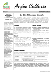
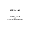
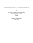
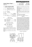
GPS 1500 User Manual
PN 2005906 Rev. C
GPS 1500 User Guide
Table of Contents
Overview 1
Introduction 2
GPS Overview 3
GPS Operation 3
Automatic Tracking 3
Receiver Performance 3
Differential Operation 4
SBAS 4
WAAS and EGNOS explained 4
Automatic SBAS tracking 4
Setup 5
Utility Setup Procedure 6
Installation 12
Installation 13
Deutsch Connector Receptacle 13
DB-9 Connection Tables 13
DB-9 Connection for Cable 4001508-18 13
HDB-15 Connection for Cable 4001509-18 14
DB-9 Connection for Cable 4001510-18 14
Cable Interface 15
Extension Power/Data Cable 15
When choosing a route for the GPS 1500 extension cable: 15
Routing the Cable to the Cab 16
Cable Part Numbers 16
Mounting the GPS 1500 17
GPS 1500 Placement on Vehicle 17
To place the GPS 1500 17
Radar Speed Output 18
Radar Speed Compatibility 18
Radar Speed Default Settings 18
Radar Speed Adaptor Cables 18
Connections to External Devices 19
Factory parameters 19
Troubleshooting 20
LED Status Indicators 21
Verifying Differential GPS Signal 21
Part Number 2005906 Rev C
ii
GPS 1500 User Guide
Troubleshooting Table 22
Appendix 23
Specifications 24
Power Specifications 24
Mechanical Specifications 24
Environmental Specifications 24
GPS 1500 Accessories 25
GPS 1500 25
GPS 1500 Documentation Accessories 25
GPS 1500 Cable Accessories 25
Company Warranty Statement 26
Product Registration 29
Part Number 2005906 Rev C
iii
Overview
OVERVIEW
Introduction
GPS Overview
GPS Operation
Differential Operation
Part Number 2005906 Rev C
1
GPS 1500 User Guide
INTRODUCTION
Congratulations on buying the Ag Leader GPS 1500. The GPS 1500 is a smart
antenna that tracks GPS and SBAS (WAAS and EGNOS) signals. This chapter provides
information on the following:
•
“GPS Overview” on page 3
•
“GPS Operation” on page 3
•
“Differential Operation” on page 4
Part Number 2005906 Rev C
2
GPS 1500 User Guide
GPS OVERVIEW
This chapter describes the various modes of operation and features of your GPS
1500 receiver and internal sensors.
For your convenience, both the GPS and differential correction of the GPS 1500 are
preconfigured. The receiver will work out of the box, and for most applications,
little user set up is necessary. When powered for the first time, the GPS 1500 will
perform a “cold start,” which involves acquiring the available GPS satellites in view
and the SBAS differential service.
GPS Operation
The GPS engine is always operating, regardless of the DGPS mode of operation. The
following sections describe the general operation of the GPS 1500 ’s internal GPS
engine.
Automatic Tracking
The GPS engine within the GPS 1500 automatically searches for GPS satellites,
acquires the signals and manages the navigation information required for
positioning and tracking.
Receiver Performance
The GPS 1500 works by finding four or more GPS satellites in the visible sky and uses
the information those satellites provide to compute an appropriate position
(typically within 2-3 meters). Since there is some error in the GPS data calculations,
the GPS 1500 also tracks a differential correction. The GPS 1500 uses these
corrections to improve its position to less than 1 meter (3 feet)
There are two main aspects of GPS receiver performance:
•
Positioning
•
Satellite acquisition quality
When the GPS 1500 is properly positioned on your vehicle, the satellites transmit
coded information to the antenna in a specific frequency that allows the receiver to
calculate a range to each satellite. GPS is essentially a timing system. The ranges are
calculated by timing how long it takes for the GPS signal to reach the GPS antenna.
The GPS receiver uses a complex algorithm incorporating satellite locations and
ranges to each satellite to calculate the geographic location. Reception of any four
or more of these signals allows a GPS receiver to compute three-dimensional
coordinates.
Part Number 2005906 Rev C
3
GPS 1500 User Guide
Differential Operation
The Radio Technical Commission of Marine services (RTCM) has a differential service
intended for correction services. This includes the Space Based Augmentation
Systems (SBAS), such as the Wide Area Augmentation System (WAAS) and the
European Geo-stationary Navigation Overlay System (EGNOS). The GPS 1500 is
compatible with each of these differential services.
SBAS
A SBAS-enabled GPS 1500 operates automatically anywhere within the coverage
areas of the WAAS, EGNOS or other SBAS programs.
WAAS and EGNOS explained
•
WAAS is a free service of the Federal Aviation Administration (FAA) that
allows regular GPS positions to be improved to a DGPS level of accuracy.
WAAS is available everywhere in the U.S., including Alaska, Hawaii and
Puerto Rico. It can also be picked up in some of the border areas of Mexico
and Canada. There are no subscription charges incurred when using WAAS.
•
EGNOS is a similar service that is available in Europe and western Russia.
Automatic SBAS tracking
The GPS 1500 will automatically scan and track satellite signals. This automatic
tracking allows you to focus on other aspects of differential operation without the
need to tune the receiver. The GPS 1500 features two-channel SBAS tracking that
provides an enhanced ability to maintain a lock on a SBAS satellite when more than
one satellite is in view. This redundant tracking approach results in more consistent
tracking of a SBAS signal when in an area where signal blockage of a satellite is
possible.
Note: For more information on Differential GPS,
see “Verifying Differential GPS Signal” on page 21
of the Troubleshooting chapter.
Part Number 2005906 Rev C
4
GPS 1500 User Guide
SETUP
Utility Setup Procedure
Part Number 2005906 Rev C
5
GPS 1500 User Guide
UTILITY SETUP PROCEDURE
The default GPS settings are 4800 baud, 1 Hz GGA and VTG NMEA strings. These
settings will work for all Ag Leader products. However, if the equipment that you
are using requires higher baud or Hertz rates, you many need to reconfigure the
GPS using the following procedure.
1. Download the Pocket Max PC.exe executable file from Ag Leader’sweb site:
http://www.agleader.com/support.php?Page=downloads
2. Double click on Pocket Max PC.exe.
3. The Pocket Max PC program appears. On the Serial Port setting, select the correct
COM Port that the GPS is connected to. Also, check the Auto Baud check box.
Pocket PC with COM Port and Auto-Baud selected
Part Number 2005906 Rev C
6
GPS 1500 User Guide
4. Press the Search button. The utility then searches for the correct GPS receiver.
Utility after finding correct GPS receiver with OK button showing
Note: If the utility cannot find the correct GPS receiver, use a
different COM port and repeat. Also, make sure that the
GPS is powered.
5. Once the utility finds the correct GPS receiver, the OK button appears at the
bottom of the window. Press the OK button.
Part Number 2005906 Rev C
7
GPS 1500 User Guide
6. When the new window appears, click the Setup tab.
7. Under the “This Port” column, (located on the left-hand side of the window) use
the drop-down menu to select the correct Hz rate, such as 5 Hz.
Selecting correct Hz rate on a NMEA string
Note: Ag Leader’s products require the GGA and
VTG NMEA strings. To find out the required NMEA
strings for other products, check with the
manufacturer.
Part Number 2005906 Rev C
8
GPS 1500 User Guide
8. At the bottom of the drop-down menu, select the correct baud rate. These range
between 4800 and 115,200.
•
Ag Leader’s PF series monitors require a 4800 baud rate.
•
Ag Leader’s InSightdisplays cannot use a baud rate higher than 38400.
Selecting correct baud rate
Note: At this time, the 57600 and 115200 baud
rates are not supported. by Ag Leader monitors.
Part Number 2005906 Rev C
9
GPS 1500 User Guide
9. When setup is complete, press on the Exit button, which is the red X
in the right-hand corner of the window.
located
10. The Exit Options window appears, asking you to choose one of the following
options. Always press Exit and Save.
Exit Options window
Note: If you choose a selection other than Exit and
Save, your settings will not be saved.
Part Number 2005906 Rev C
10
GPS 1500 User Guide
11. A series of messages appears, after which a Configuration Report will appear. At
the configuration report, you can view your saved settings. However, you cannot
make changes to these settings at this window
New Receiver Configuration Report
12. Press Close to end the utility program.
Part Number 2005906 Rev C
11
GPS 1500 User Guide
INSTALLATION
Cable Attachment Information
Mounting the GPS 1500
Powering the GPS 1500
Connecting GPS 1500 to External Devices
Part Number 2005906 Rev C
12
GPS 1500 User Guide
INSTALLATION
The GPS 1500 is a smart antenna that tracks GPS and SBAS (WAAS and EGNOS).
Deutsch Connector Receptacle
The picture below provides a front view of the Deutsch connector receptacle’s
numbering.
Deutsch connector receptacle numbering
DB-9 Connection Tables
DB-9 Connection for Cable 4001508-18
Signal
GPS
Wire Color
DB-9
Manual Mark In
1
Violet
6
TXB
2
White
RXB
3
Gray
Can High
4
Pink
Signal Ground
5
Brown
TXA
6
Green
One PPS
7
Orange
RXA
8
Blue
Can Low
9
Tan
Power In (12V)
10
Red
4
Power Ground
11
Black
5
Speed Out
12
Yellow
Deutsch
Receptacle
3
2
2 (Black)
1 (White)
Part Number 2005906 Rev C
13
GPS 1500 User Guide
HDB-15 Connection for Cable 4001509-18
Signal
GPS
Wire Color
HDB 15
Manual Mark In
1
Violet
5
TXB
2
White
RXB
3
Gray
Can High
4
Pink
Signal Ground
5
Brown
TXA
6
Green
One PPS
7
Orange
RXA
8
Blue
Can Low
9
Tan
Power In (12V)
10
Red
10
Power Ground
11
Black
11
Speed Out
12
Yellow
Deutsch
Receptacle
14
13
2 (Black)
1 (White)
DB-9 Connection for Cable 4001510-18
Signal
GPS
Wire Color
Manual Mark In
1
Violet
TXB
2
White
RXB
3
Gray
Can High
4
Pink
Signal Ground
5
Brown
TXA
6
Green
One PPS
7
Orange
RXA
8
Blue
Can Low
9
Tan
Power In (12V)
10
Red
Power Ground
11
Black
Speed Out
12
Yellow
DB-9
Deutsch
Receptacle
Cigarette Plug
2
3
1 (White)
5
2 (Black)
2 (Black)
1 (White)
Part Number 2005906 Rev C
14
GPS 1500 User Guide
CABLE INTERFACE
The cable options include:
•
DB9 serial
•
Speed
•
Power
Additional extension cables may be purchased, as necessary, for other installations.
This allows the GPS 1500 to be quickly and easily moved from one installation to
another. If an extension cable is damaged in the field, it can be replaced without
returning the complete GPS 1500 system.
Other power cables are available as accessories to fit a wide variety of applications.
For a list of GPS 1500 accessories, see “GPS 1500 Accessories” on page 25.
Extension Power/Data Cable
The GPS 1500 system is quickly installed with one of the various extension cables.
Keep in mind that the data connector communication port must reach to connect to
a data storage device or guidance system.
When choosing a route for the GPS 1500 extension cable:
•
Avoid running cables in areas of excessive heat.
•
Keep cables away from corrosive chemicals.
•
Keep the cables away from rotating machinery.
•
Do not bend excessively or crimp the cables.
•
Avoid placing tension on the cables.
•
Remove unwanted slack from the extension cable at the receiver end.
•
Secure along the cable route using plastic wraps.
Improperly-installed cables near machinery can be
dangerous.
Part Number 2005906 Rev C
15
GPS 1500 User Guide
Routing the Cable to the Cab
Follow these steps to route cable into the cab:
1. Find a place on the right side or bottom of the cab to route cable into cab (the
point of entry is up to you).
Note: The cable can be routed through windows
or doors but make sure that there will be no
damage to the cable.
2. Attach the GPS cable from the antenna to Port 1 of the PF3000, Port 1 on the YM
2000, or the GPS port on the InSight display.
•
If you are attaching the GPS1500 to a PF Advantage or PF 3000 Pro without
GPS, attach the GPS cable to AUX. 1 Port.
•
If you are connecting your GPS1500 to an alternative logging or mapping
device (i.e. handheld or laptop computer), refer to your Operator's Manual
for that particular unit for correct cable connection.
Cable Part Numbers
See the following table for the appropriate cable for your installation.
Display
Cable Part Number
InSight
4001508-18
PF 3000
YM 2000
PF Advantage
4001509-18
Mobile Logging
4001510-18
•
Laptop
•
Handheld
Part Number 2005906 Rev C
16
GPS 1500 User Guide
MOUNTING THE GPS 1500
GPS 1500 Placement on Vehicle
Placement of the GPS 1500 is crucial to the system’s operation. The GPS engine
inside the GPS 1500 computes a position based upon measurements from each
satellite to the internal GPS antenna unit. Mount the GPS 1500 on your point of
interest. When choosing a location to mount the antenna, please make certain that
there is an unobstructed view of the sky available to the GPS 1500 smart antenna.
This will ensure that GPS satellites are not masked by obstructions, which can
potentially reduce system performance.
To place the GPS 1500
1. Mount the GPS 1500 on, or as close to, the center of your point of measurement.
2. Position the GPS 1500 as high as possible.
Below is an illustration of the ideal location to place the GPS 1500 on a vehicle.
GPS 1500 placement on a vehicle
Part Number 2005906 Rev C
17
GPS 1500 User Guide
RADAR SPEED OUTPUT
The GPS 1500 is capable of outputting a simulated radar speed pulse. This simulates
a similar pulse output that you would receive from a standard radar gun.
To use the radar speed input you must set the speed input to RADAR under the
appropriate setup screen for the monitor/display. Additional cables will also be
required to obtain the simulated speed output. Contact Ag Leader’s Technical
Support team for these additional cables.
Radar Speed Compatibility
Adaptor cables are available through Ag Leader Technology for the following three
brands of monitors: Dickey-John, Raven, and Hiniker. These adaptor cables provide
the ability to use the GPS 1500 in place of a radar gun. If using the GPS 1500 as a
stand-alone antenna, you will need to obtain an Auxiliary Power/Data Cable and the
appropriate Radar Speed Adaptor Cable.
Radar Speed Default Settings
The default output parameter provided in the GPS 1500 is a minimum output speed
of .5 miles per hour (.8 kilometers per hour), meaning speed pulses will not be
output below this speed. The default radar pulse output rate is 45 Hz per 1 MPH.
Radar Speed Adaptor Cables
Cable Name
Part Number
Hiniker adaptor cable
3000478
Raven adaptor cable
3000479
Dickey John adaptor cable
3000480
Part Number 2005906 Rev C
18
GPS 1500 User Guide
CONNECTIONS TO EXTERNAL DEVICES
The serial ports of the GPS 1500 operates at the RS-232C interface level to
communicate with external data loggers, navigation systems and other devices. The
serial ports are accessible via the extension cable that features a DB9 female data
connector. The serial ports are also used for firmware updates.
Note: For successful communication, the baud rate of the GPS
1500 serial ports must be set to match that of the devices to
which they are connected.
The picture below displays the numbering for the extension cable’s DB-9 socket
connector (female). The associated numbering for the plug connector (male) is a
mirror reflection of the scheme shown below.
DB-9 socket numbering
Factory parameters
Serial Port Settings
This table identifies default settings for the GPS 1500 configuration.
Serial Port
Baud
Rate
Serial port A 4800
9600
38400
57600
Data
Bits
Parity
Stop
Bit
Interface
Levels
Update
Rate
8
None
1
RS-232C
1 to 10 Hz
Part Number 2005906 Rev C
19
Troubleshooting
TROUBLESHOOTING
LED Status Indicators
Verifying Differential GPS Signal
Troubleshooting Table
Part Number 2005906 Rev C
20
GPS 1500 User Guide
LED Status Indicators
The GPS 1500 uses one tri-colored LED, which indicates important status
information.
•
Red indicates the power is on
•
Amber indicates a GPS lock
•
Flashing green indicates DGPS is being acquired
•
Green indicates a DGPS solution
Verifying Differential GPS Signal
Differential GPS (DGPS) is a data collection technique that uses extra GPS receivers
and some complex calculations to increase the accuracy of GPS positions. DGPS is
made possible because of an enhancement to the Global Positioning System that
uses a network of fixed, ground-based reference stations to broadcast the
difference between the positions indicated by satellite systems and other known
fixed positions.
For more information on Differential GPS, see
“Differential Operation” on page 4 of the
Overview chapter.
You should periodically check the monitor to ensure that you are receiving a
Differential GPS signal, as this could affect the quality of the data you are logging.
As an example, your GPS receiver must track four or more satellites to get an
elevation reading.
Part Number 2005906 Rev C
21
GPS 1500 User Guide
TROUBLESHOOTING TABLE
The following table provides a checklist to troubleshoot common problems and
their solutions for the GPS 1500.
Problem
Receiver fails
to power
No data from
GPS 1500
No GPS lock
No SBAS lock
Possible solution
•
Verify polarity of power leads
•
Check integrity of power cable connections
•
Check power input voltage
(7 - 36 VDC)
•
Check current restrictions imposed by power source
(maximum is 250 mA)
•
Check receiver power status (LED)
•
Check integrity and connectivity of power and data
cable connections
•
The volume of data requested to be output by the
GPS 1500 could be higher than what the current baud
rate supports. Try using 4800, or higher, as the baud
rate for all devices.
•
Check integrity of cable connections
•
Verify GPS 1500 ’s unobstructed view of the sky
•
Check integrity of cable connections
•
Verify GPS 1500 ’s unobstructed view of the sky
•
Check SBAS visibility map
Part Number 2005906 Rev C
22
Appendix
APPENDIX
GPS 1500 Specifications
GPS 1500 Accessories
Warranty
Part Number 2005906 Rev C
23
GPS 1500 User Guide
SPECIFICATIONS
The following three tables provide the power, mechanical, communication,
environmental and DGPS specifications for the GPS 1500.
Power Specifications
Item
Specification
Input voltage
7 - 36 VDC
Power consumption
< 2 W @ 12 VDC (typical)
Current Consumption
150 mA @ 12 VDC (typical)
Power connector
Cable mount environmentally sealed
Mechanical Specifications
Item
Specification
Height
54.7 mm (2.2in)
Width
129.5 mm (5.1 in)
Weight
0.66 kg (1.45 lbs)
Mounting Options
Magnetic mount
Environmental Specifications
Item
Specification
Operating temperature
-30° C to +70° C
(-22° F to + 158° F)
Storage temperature
-40° C to +85° C
(-40° F to + 185° F)
Humidity
100%
Enclosure
Waterproof and dust proof
Compliance
FCC, CE
Shock
IEC 68-2-27
Vibration
ISO 16750-1
EMI certification
FCC part 15, E-Mark
Part Number 2005906 Rev C
24
GPS 1500 User Guide
GPS 1500 ACCESSORIES
The tables below provide the available accessories for the GPS 1500.
GPS 1500
Ag LeaderPart
Number
Item
4001372
GPS 1500 Receiver
2000161
Antenna Bracket - L-shaped
GPS 1500 Documentation Accessories
Ag
LeaderPart
Number
Documentation
2005906
GPS 1500 User Manual
2002868
Product Registration
GPS 1500 Cable Accessories
Ag Leader
Part Number
Cables
4001508-18
Cable for YM 2000, PF 3000, and
InSight display.
4001509-18
Cable for PF Advantage.
4001510-18
Cable for Cigarette Power/12V
connector.
For more information on cable attachments, see “Routing the Cable to the Cab” on
page 16 in the Installation chapter.
Part Number 2005906 Rev C
25
GPS 1500 User Guide
COMPANY WARRANTY STATEMENT
WARRANTY
Ag Leader Technology will repair or replace at no charge any component of the GPS
1500 that fails during normal service, while being used in an approved application,
within two years of the warranty start date. Warranty is not provided for damage
resulting from abuse, neglect, accidents, vandalism, acts of nature, or any causes
that are outside of the normal intended use of the GPS 1500. Ag Leader Technology
shall not be liable for indirect, incidental, or consequential damages to the dealer,
end user, or third parties arising from the sale, installation, or use of any Ag Leader
Technology product.
COPYRIGHT NOTICE
Ag Leader Technology has copyrighted (© 2007) the contents of this manual. No
reproductions may be made without first obtaining the consent of Ag Leader
Technology.
SERVICE
AND
SUPPORT
If you have additional questions or feel that you may be having a problem with your
system, call your local Ag Leader Technology dealer or call us directly at the phone
number below. If we determine you have a hardware failure, we will ship
replacement hardware immediately.
Our Technical Support Department can be reached by phone at 515-232-5363,
extension #1; or through email at [email protected].
Part Number 2005906 Rev C
26
Differential Operation 4
Index
E
EGNOS 4
environmental specifications 24
extension cable 15
choosing route 15
Extension Power/Data Cable 15
external device connections 19
Numerics
12V connector cable 25
A
accessories 25
automatic tracking 3
F
factory parameters 19
B
baud rate 22
G
GPS
no lock 22
operation 3
C
cable
data 15
DB-9 connection 13
Dickey John 18
extension 15
Hiniker 18
Raven 18
routing 16
cable accessories 25
cable interface 15
cables
improperly installed 15
cigarette power
cable 25
I
input voltage 24
InSight
cable 25
installation 12
mounting 17
L
LED 21
amber 21
colors 21
flashing green 21
green 21
red 21
D
data cable 15
data not coming from GPS 1500 22
DB-9 connection 13, 14
mobile 14
DB-9 socket 19
DB-9 socket numbering 19
Deutsch connector
numbering 13
DGPS 4
verifying 21
differential
corrections 3
differential GPS 4
verifying 21
M
mechanical specifications 24
mounting 17
O
operating temperature 24
P
PF 3000
cable 25
Part Number 2005906 Rev C
27
PF Advantage
cable 25
DB-9 connection 14
positioning 3
power cable connection 22
power connector 24
power consumption 24
power input voltage 22
power specifications 24
Y
YM 2000
cable 25
R
radar pulse output rate 18
radar speed adaptor cables 18
radar speed compatibility 18
radar speed default settings 18
radar speed output 18
receiver
not powered 22
receiver performance 3
positioning 3
satellite acquisition 3
RS-232C 19
S
SBAS 4
no lock 22
tracking 4
visibility map 22
serial port settings 19
setup 5
specifications 24
environmental 24
mechanical 24
power 24
storage temperature 24
T
troubleshooting 22
U
utility setup 6
W
WAAS 4, 4
warranty 26
Part Number 2005906 Rev C
28
GPS 1500 User Guide
PRODUCT REGISTRATION
Ag Leader Technology stands by all new products with a two-year limited warranty from the
warranty start date. The warranty start date will initially be set to the date on which your
product is shipped from Ag Leader Technology.
If you return this registration/warranty card within 30 days of purchasing this product from your
dealer, the warranty start date will be changed to the date that you purchased the product from
your dealer. Ag Leader Technology reserves the right to request proof of the date of purchase
stated.
Timely product registration will allow you to receive important product bulletins, upgrade
information, and notice regarding product training in your area.
TO REGISTER:
Register On-Line at www.agleader.com. Click on Product Registration from the Quick Links list
on the Ag Leader Home Page.
OR
Return this sheet in the enclosed postage-paid envelope; or by FAX: 515-232-3595.
Ag Leader Technology
2202 South Riverside Drive
P.O. Box 2348
Ames, Iowa 50010
Name:____________________________________________________________________________
Street Address:_____________________________________________________________________
City, State, ZIP: _____________________________________________________________________
Phone # (including area code):________________________________________________________
Mobile Phone #: ________________________
Fax #: ____________________________________
Email address:______________________________________________________________________
Ag Leader Dealer:___________________________________________________________________
Date Purchased:_____________________________________________________________________
GPS Antenna Serial #:________________________________________________________________
29