1
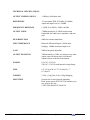
DA1000
DISTRIBUTION AMPLIFIER
OPERATING AND MAINTENANCE MANUAL
© Copyright 2011, ATI Audio Inc.
ATI Audio Inc.
■ Tel: 856-626-3480
■
Fax: 856-504-0220
■ [email protected]
■
www.
audio.com
DESCRIPTION
The DA1000 is a 1X8 Analog Audio Distribution amplifier. A single balanced bridging
input is level-regulated via a front panel level control and the signal is sent to eight
balanced differential outputs and a front panel mounted headphone jack. Power, Signal
Present and Output Clipping indicators are located on the front panel.
The ICs developed primarily for the instrumentation market had many shortcomings
when used in high quality audio applications. The lack of audio related specifications,
crossover distortion, high noise for low source impedances, limited output capability and
limited gain bandwidth product forced many compromises when used in audio systems.
High ratio input transformers, output boost stages and multiple stage designs were all
used to compensate for op amp deficiencies and in turn added additional response and
distortion problems of their own.
Walter Jung, in a definitive series of articles, analyzed and defined slew rate induced
distortion mechanisms, tested many commonly available ICs and correlated various
distortion tests with subjective (listening) criteria. A very significant result of his efforts
was the identification of an IC originally developed for the European professional audio
market which has almost ideal characteristics for audio use and in particular provides a
high slew rate capability of 13 volts/microsecond, virtually eliminating slew induced
Transient Intermodulation Distortion. By contrast the old standard 741-op amp has a slew
rate of only .6V/microsecond.
This op amp is now available from several U.S. Manufacturers in single and dual
versions and forms the basis for the DA1000. This chip incorporates an input stage
designed for excellent noise performance with a wide range of source impedances, thus
eliminating the necessity for input step up transformers. An output stage capable of
driving 600 ohm loads directly to +22dBm with total freedom from crossover distortion,
high inherent linearity, 100dB open loop gain and 50 MHz gain bandwidth product make
this an ideal device for highest quality audio. The absence of Transient Intermodulation
Distortion may be detected by the smooth effortless high frequency output capability, the
absence of the harsh, raspy sound typical of IC amplifiers driven to full output at high
frequencies and the freedom from increasing harmonic distortion vs. frequency. As used,
a minimum of 40dB of loop gain is available for 100:1 distortion reduction even at
20kHz. All program audio stages in the Distribution Amplifiers use this unique device in
its dual version (NE5533).
INPUT
Input audio feeds a unity gain balanced differential input buffer stage (Al), which
presents 30,000-ohm bridging impedance to the source. The inputs are protected from
over voltage signals by clipping diodes (CR4-CR7). Dual bypass capacitors (C7, C29 and
C8, C39) protect the inputs against common mode RFI pickup. A balance potentiometer
(R9) allows setting a precise null for common mode hum inputs.
ATI Audio Inc.
■ Tel: 856-626-3480
■
Fax: 856-504-0220
■ [email protected]
■
www.
audio.com
SIGNAL PRESENT INDICATOR
The second half of Al monitors the voltage at the output of the input buffer IC. The green
Signal Present LED on the front panel will light for audio inputs over -30dBm. The LED
will normally flicker with applied program material to tell you that all is well. (Happiness
is a green LED.)
OUTPUTS
Audio from the input buffer is AC coupled to the front panel level adjust potentiometer.
This control adjusts the level of all outputs. If you are afflicted with lurking knob
twiddlers, the knob can be removed leaving a somewhat less inviting screwdriver
adjustment. If removing the knob doesn't cure the problem, put your DA out of reach by
sticking it to the ceiling using the supplied suction cup feet.
The pot output is applied to the non-inverting input of the HI (in-phase) output stage
driver IC (A2-1). The IC supplies the first 10 mA of output current directly and then the
complementary Class B output booster transistors (Q1 and Q2) take over. The unique,
wide bandwidth, high slew rate circuit design provides effective class AB operation with
minimal crossover distortion from a power output stage operating true Class B with zero
quiescent power dissipation.
The HI output bus is applied to the inverting input of A2-2 in a unity gain, phase
inverting configuration and boosted by Q3 and Q4 to form the LO output bus.
The HI and LO output buses are split into nine individual outputs (eight rear and one
front panel jack) through 150 ohm build-out resistances. All outputs will tolerate short
circuits across the output or to ground without damage. Up to two outputs can be shorted
with no significant reduction in headroom. Needless to say, this is NOT the
recommended mode of operation. Do not drive single-ended (one side grounded) loads
from both HI and LO outputs together. Drive single ended loads from either the HI or LO
outputs to ground. Up to 18 single-ended 600-ohm output loads may be simultaneously
driven.
The build-out resistors are split and heavily bypassed to prevent RF pickup on the output
lines from affecting operation of the DA. These bypasses will place a very heavy load on
the outputs under sustained sine wave operation above 20kHz and such operation may
over-dissipate the 47 ohm build-out resistors—don't do it!
OUTPUT CLIPPING INDICATOR
The differential input voltage of HI output driver IC (A2-1) is monitored by A3. The
differential voltage is under a few millivolts under linear operation; however, if the
output is driven to clipping, the differential voltage rapidly increases and is amplified to
ATI Audio Inc.
■ Tel: 856-626-3480
■
Fax: 856-504-0220
■ [email protected]
■
www.
audio.com
light the yellow OUTPUT CLIPPING LED. Conserve power—try not to light the yellow
LED.
HEADPHONE OUTPUT
The front panel headphone jack provides a ninth output with its own set of build-out
resistors. The phone jack is a convenient metering point, an auxiliary output or
headphone output. The jack is wired primarily to drive stereo headphones with an inphase mono signal; consequently tip (red) and ring (blue) are wired together and to the HI
output, and the sleeve connection (white) is wired to the LO output. To use a standard tipring-sleeve patchcord output, rewire the jack terminals by removing the blue wire from
the ring terminal, moving the white wire to the ring connection (and grounding the sleeve
terminal to the top shield foil of the P.C. board).
POWER SUPPLY
The DA1000’s internal power supply incorporates a couple of unique regulating devices
called zener diodes. In contrast to most fancy IC regulators, these devices will live
through most line transients and simultaneously protect your expensive circuitry. As
further insurance, a varistor suppresser is placed across the power transformer secondary.
INSTALLATION
MOUNTING
Your DA1000 may be desk mounted on its non-slip suction cups. Rack mount system
21075-501 mounts one or two units in one rack. A 1/2RU Filler Panel, Part Number
21098-501, may be used to tidy up the installation.
WIRING
The attached line cord contains a three wire grounded plug. The third wire ground can
cause a ground loop with your facility ground. If you are sure your facility ground will
provide adequate protection to personnel in case of an AC line short to chassis, a 3-to-2
AC adapter can be used to isolate the power line ground. We recommend that the adapter
be removed and the power line ground reconnected prior to any service work requiring
removal of the facility ground from the chassis.
The four-inch silver bearing copper strap, which you are, of course, using for your
facility ground is not going to fit around the #6 chassis ground screw on the rear panel.
Run the strap to within a few inches of the chassis and jump to the chassis ground with
shield braid.
ATI Audio Inc.
■ Tel: 856-626-3480
■
Fax: 856-504-0220
■ [email protected]
■
www.
audio.com
Audio inputs and outputs should be connected using the rear panel labels as a guide. HI
outputs are all in phase with each other and in phase with the HI inputs. Fanning strips
are provided so that our ears won't be burning in the middle of the night while you are
trying to wrap wires around tiny barrier strip screws. The fanning strips are Kulka part
number 649A22 and extras are available from our Parts and Accessories Department.
To allow maximum flexibility in grounding in high RF environments, the circuit grounds
are isolated from case ground. For normal operation, add a ground jumper from the
barrier strip ground terminal closest to the inputs to the chassis ground screw.
CAUTION
The balanced differential outputs have active drivers for both HI and LO output
terminals. DO NOT GROUND either HI or LO terminals. To drive an unbalanced
(one side grounded) load, connect it between HI and GND terminals and let the LO
terminal float. Two separate 600 ohm unbalanced loads can be driven from each output
without interaction by connecting one between HI and GND and the other between LO
and GND. The two loads thus driven will be out of phase with each other.
MAINTENANCE NOTES
Power supply voltages are + and - 20 VDC nominal. Maximum allowable voltages are
±22 VDC (limited by IC). If zeners are replaced, remove ICs and check output voltage
before plugging ICs back into the circuit. Remove power when inserting or removing
ICs.
IC output DC voltages (no signal conditions) should measure 0VDC ± .5 VDC.
Significant deviation indicates an IC or circuit problem. Measurable DC difference
between HI and LO amplifier inputs (other than due to meter loading) indicates IC
failure.
If hit by lightning, replace Al through A3.
MODIFICATIONS
230 VAC OPERATION
Your DA1000 is wired for 115 VAC 50/60 Hz operation unless otherwise requested at
the time of ordering. It can be modified for 230 VAC use by removing the power
transformer primary jumpers J1 and J3 and inserting a jumper in the J2 holes.
GAIN
To increase gain by 10dB, change R13 to 680 ohms and increase C15 to 68 µF.
ATI Audio Inc.
■ Tel: 856-626-3480
■
Fax: 856-504-0220
■ [email protected]
■
www.
audio.com
TECHNICAL SPECIFICATIONS
OUTPUT CLIPPING LEVEL
+24dBm @ 600 ohms load
DISTORTION
.2% maximum THD, 20-20kHz @+24dBm
output and input levels to +24dBm
FREQUENCY RESPONSE
±.25dB, 20 to 20kHz; -3dB at 100 kHz
OUTPUT NOISE
-70dBm maximum @ 20kHz measurement
bandwidth, 600 ohm source impedance and max
gain
HUM REJECTION
80dB for common mode hum
INPUT IMPEDANCE
Balanced differential inputs, 30,000 ohms
bridging. +24dBm maximum input level
GAIN
26dB, front panel adjustable
OUTPUT ISOLATION
70dB minimum at 1 kHz, any output to any other
output; unit will tolerate up to two shorted
outputs with no reduction in headroom
POWER
115VAC, 47-63 Hz
230VAC, 47-63 Hz with internal wiring change
SIZE
8.5" (21.6cm) W x 1.75" (4.4cm) H x 7"
(17.8cm) D
WEIGHT
2.5 lbs. (1.1kg) Net, 4 lbs. (1.8kg) Shipping
MOUNTING
Suction feet for non-slip desk mounting
Rack mount system P/N 21075-501 mounts up to
two units in one rack
1/2RU Filler Panel P/N 21098-501
ATI Audio Inc.
■ Tel: 856-626-3480
■
Fax: 856-504-0220
■ [email protected]
■
www.
audio.com
One Year Limited Warranty
ATI warrants this product to be free from defects in materials and workmanship to its original
owner for a period of one year from date of purchase. ATI will repair or replace such product or
part thereof, which upon inspection by ATI, is found to be defective in materials or workmanship.
The Proper Return Authorization Number must be obtained from ATI in advance of return.
Contact ATI at 856-626-3480 or email [email protected] to receive the number and
instructions for return of your unit.
A written statement providing the name, address, daytime telephone number and email address
of the original owner, together with receipt from the original purchase, and a brief description of
any claimed defects, must accompany all returns. Parts or product for which replacement is made
shall become the property of ATI.
The customer shall be responsible for costs of transportation and insurance to the factory of ATI,
and shall be required to prepay such costs.
ATI shall use reasonable efforts to repair or replace any product covered by this limited warranty
within thirty days of receipt. In the event repair or replacement shall require more than thirty days,
ATI shall notify the customer accordingly. ATI reserves the right to replace any product that has
been discontinued from its product line with a new product of comparable value and function.
This warranty shall be void in the event a covered product has been damaged, or failure is
caused by or attributable to acts of God, abuse, accident, misuse, improper or abnormal usage,
failure to follow instructions, improper installation or maintenance, alteration, or lightning, power
fluctuations and other incidental or environmental conditions. Further, product malfunction or
deterioration due to normal wear is not covered by this warranty.
ATI DISCLAIMS ANY WARRANTIES, EXPRESS OR IMPLIED, WHETHER OF
MERCHANTABILITY OF FITNESS FOR A PARTICULAR USE, EXCEPT AS EXPRESSLY SET
FORTH HEREIN. THE SOLE OBLIGATION OF ATI UNDER THIS LIMITED WARRANTY SHALL
BE TO REPAIR OR REPLACE THE COVERED PRODUCT, IN ACCORDANCE WITH THE
TERMS SET FORTH HEREIN. ATI EXPRESSLY DISCLAIMS ANY LOST PROFITS, GENERAL,
SPECIAL, INDIRECT OR CONSEQUENTIAL DAMAGES WHICH MAY RESULT FROM
BREACH OF ANY WARRANTY, OR ARISING OUT OF THE USE OR INABILITY TO USE ANY
ATI PRODUCT.
Some states do not allow the exclusion or limitation of incidental or consequential damages or
limitation on how long an implied warranty lasts, so the above limitations and exclusions may not
apply to you.
This warranty gives you specific legal rights, and you may also have other rights that vary from
state to state.
ATI reserves the right to modify or discontinue, without prior notice to you, any model or style
product.
If warranty problems arise, or if you need assistance in using your product contact us.
ATI Audio Inc.
■ Tel: 856-626-3480
■
Fax: 856-504-0220
■ [email protected]
■
www.
audio.com