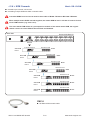
1
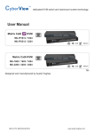
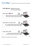
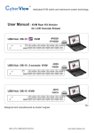
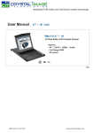
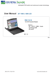
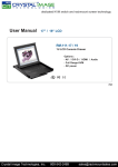
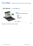
dedicated KVM switch and rackmount screen technology
User Manual - KVM Rear Kit Version
for LCD Console Drawer
Matrix DB-15
KVM
Matrix DB-15 KVM
-MIP813 / 824
-MIP1613 / 1624
-M802 / 803 / 804
-M1602 / 1603 / 1604
back
back
751
Designed and manufactured by Austin Hughes
UM-CV-751-MKVM-KIT-Q215V3
www.austin-hughes.com
Legal Information
First English printing, October 2002
Information in this document has been carefully checked for accuracy; however, no guarantee is given to the correctness
of the contents. The information in this document is subject to change without notice. We are not liable for any injury or
loss that results from the use of this equipment.
Safety Instructions
Please read all of these instructions carefully before you use the device. Save this manual for
future reference.
■
■
■
■
■
■
■
■
■
■
■
Unplug equipment before cleaning. Don’t use liquid or spray detergent; use a moist cloth.
Keep equipment away from excessive humidity and heat. Preferably, keep it in an air-conditioned environment with
temperatures not exceeding 40º Celsius (104º Fahrenheit).
When installing, place the equipment on a sturdy, level surface to prevent it from accidentally falling and causing
damage to other equipment or injury to persons nearby.
When the equipment is in an open position, do not cover, block or in any way obstruct the gap between it and the
power supply. Proper air convection is necessary to keep it from overheating.
Arrange the equipment’s power cord in such a way that others won’t trip or fall over it.
If you are using a power cord that didn’t ship with the equipment, ensure that it is rated for the voltage and current
labeled on the equipment’s electrical ratings label. The voltage rating on the cord should be higher than the one listed
on the equipment’s ratings label.
Observe all precautions and warnings attached to the equipment.
If you don’t intend on using the equipment for a long time, disconnect it from the power outlet to prevent being
damaged by transient over-voltage.
Keep all liquids away from the equipment to minimize the risk of accidental spillage. Liquid spilled on to the power
supply or on other hardware may cause damage, fire or electrical shock.
Only qualified service personnel should open the chassis. Opening it yourself could damage the equipment and
invalidate its warranty.
If any part of the equipment becomes damaged or stops functioning, have it checked by qualified service personnel.
What the warranty does not cover
■
■
■
Any product, on which the serial number has been defaced, modified or removed.
Damage, deterioration or malfunction resulting from:
Accident, misuse, neglect, fire, water, lightning, or other acts of nature, unauthorized product modification, or
failure to follow instructions supplied with the product.
Repair or attempted repair by anyone not authorized by us.
Any damage of the product due to shipment.
Removal or installation of the product.
Causes external to the product, such as electric power fluctuation or failure.
Use of supplies or parts not meeting our specifications.
Normal wear and tear.
Any other causes which does not relate to a product defect.
Removal, installation, and set-up service charges.
□
□
□
□
□
□
□
□
Regulatory Notices Federal Communications Commission (FCC)
This equipment has been tested and found to comply with the limits for a Class B digital device, pursuant to Part 15 of
the FCC rules. These limits are designed to provide reasonable protection against harmful interference in a residential
installation.
Any changes or modifications made to this equipment may void the user’s authority to operate this equipment. This
equipment generates, uses, and can radiate radio frequency energy and, if not installed and used in accordance with the
instructions, may cause harmful interference to radio communications.
However, there is no guarantee that interference will not occur in a particular installation. If this equipment does cause
harmful interference to radio or television reception, which can be determined by turning the equipment off and on, the
user is encouraged to try to correct the interference by one or more of the following measures:
■ Re-position or relocate the receiving antenna.
■ Increase the separation between the equipment and receiver.
■ Connect the equipment into an outlet on a circuit different from that to which the receiver is connected.
UM-CV-751-MKVM-KIT-Q215V3
www.austin-hughes.com
Contents
< Part 1 > Matrix DB-15
1.1
1.2
1.3
1.4
1.5
1.6
1.7
KVM Kit
M-IP813
M-IP824
M-IP1613
M-IP1624
Package contents
KVM port connection
IP & Remote console connection
IP console setting
Important Preconfiguration for IP console
KVM Cascade
Specifications
P.1
P.2
P.3 - 4
P.5
P.6 - 7
P.8
P.9
< Part 2 > Matrix DB-15 KVM Kit
M-802
M-803
M-804
M-1602
M-1603
M-1604
2.1
2.2
2.3
Package contents
KVM port connection
Remote console connection
2.4
2.5
KVM Cascade
Specifications
P.11 - 12
P.13
P.14 - 15
P.16
P.17
< Part 3 > Usage
3.1
3.2
3.3
3.4
3.5
KVM Button
Password
KVM OSD
KVM Hotkey & Remote Console Hotkey
Resolution Support Information
UM-CV-751-MKVM-KIT-Q215V3
P.18
P.19
P.20
P.21
P.22
www.austin-hughes.com
< Part 1 > Matrix DB-15
< 1.1 > Package Contents
-MIP813 / -MIP1613
-MIP824 / -MIP1624
KVM
Matrix DB-15 IP KVM
•
Receiver box for remote console x 1
•
Power adapter w/ power cord ( for receiver ) x 1
•
CE-6 6ft Combo KVM cable for receiver box x 1
KVM Rear Kit
back
-MIP813
Remote Console 1
Power
1
Cascade
-MIP1613
2
Power
1
-MIP824
Remote Console 1
Cascade
-MIP1624
UM-CV-751-MKVM-KIT-Q215V3
P.1
www.austin-hughes.com
< 1.2 > KVM port connection
Matrix DB-15 IP KVM
USB Servers
CE - 6 / 10 / 15 Combo KVM cable
support PS/2 or USB server
DB-15 Combo KVM port
Drawer KVM Rear Kit
PS/2 Servers
CE - 6 / 10 / 15 Combo KVM cable
support PS/2 or USB server
CE-6 / CE-10 / CE-15
■ 6 / 10 / 15 ft Combo KVM cable
■ Support PS/2 or USB server
UM-CV-751-MKVM-KIT-Q215V3
P.2
www.austin-hughes.com
< 1.3 > IP & Remote console connection
Matrix DB-15 IP KVM
Inter net
Network device
hub or router
CAT 5 / 6 cable
max. 100m
Remote
USB console
Receiver
CAT 5 / 6 cable
max. 150m
2
Remote
Cat6
Console 1
Drawer KVM Rear Kit
1
Inter net
Network device
hub or router
CAT 5 / 6 cable
max. 100m
UM-CV-751-MKVM-KIT-Q215V3
P.3
www.austin-hughes.com
How to use a receiver to connect a remote console
Receiver
Local
Computer
Matrix DB-15 IP KVM
Monitor
Remote I/O
Front
Rear
Power
USB
K/B
Local
Mouse
Remote
Button
to
PC
Button
to
KVM switch
The receiver provides a hotkey function for remote console. Please refer to P.19
Drawer KVM Rear Kit
Monitor
Remote
Console
Local computer
( Optional setup )
CE-6
Combo
KVM cable
VGA
cable
Cat6 cable
up to 150m
12V DC Power
Adapter
Front
Rear
UM-CV-751-MKVM-KIT-Q215V3
P.4
www.austin-hughes.com
< 1.4 > IP console setting
Matrix DB-15 IP KVM
After the cable connection, please take the following steps to configure the IP KVM :
1. Download IPKVMsetup.exe from the link:
www.austin-hughes.com/support/utilities/cyberview/IPKVMsetup.exe
2. Double click IPKVMsetup.exe to configure the IP KVM by device setup as below.
3. Click Refresh Device to search the connected IP KVM
4. Select the M.A.C. address, which you want to setup, then click Query Device
5. Enter Super user login. The default is super
6. Enter Super user password. The default is pass
7. Enter the new super user password
8. Re-enter the new password
9. Change the desired IP address / Subnet mask / Gateway, then click Setup Device to confirm the setting to IP KVM
10. The default address is as below:-■ The single IP KVM model, such as M-IP1613 - http://192.168.1.22
■
The dual IP KVM model,
such as M-IP1624
- http://192.168.1.22 (for 1st IP)
http://192.168.1.23 (for 2nd IP)
11. Open Internet Explorer ( I.E. ), version 6.0 or above
12. Enter the IP KVM address into the address bar
- For Single IP - http://192.168.1.22
- For Dual IP - http://192.168.1.22 ( for 1st IP )
http://192.168.1.23 ( for 2nd IP )
13. Enter username ( default is super )
Password ( default is pass )
14. After successful login to IP KVM, the user will enter the main page of IP KVM
The setting is enough for intranet.
If the users access KVM GUI via internet, please ask MIS for assistance and
download IP KVM user manual from the link :
www.austin-hughes.com/support/usermanual/cyberview/UM-CV-IP.pdf
UM-CV-751-MKVM-KIT-Q215V3
P.5
www.austin-hughes.com
< 1.5 > Important Preconfiguration for IP console
Matrix DB-15 IP KVM
You must complete the following tasks after the IP console setting is performed.
( 1 ) TARGET SERVER SETUP **Servers connected to KVM
Resolution
The IP KVM remote console recognizes several varieties of video display formats with resolutions up to 1600 x
1200 @60Hz. (Refer to the User Manual for a list of supported video formats). Minimize bandwidth by setting the
target server’s video resolution to the minimum setting required for your remote monitoring application.
The following video modes are recommended:
(i) 800 x 600 @ 60Hz
(ii) 1024 x 768 @ 60Hz
(iii) 1280 x 1024 @ 60Hz
On a Windows target server system, select Control Panel > Display > Settings.
Modify the screen resolution value as necessary.
Mouse
Use generic mouse drivers for optimum mouse control during remote sessions. Set the mouse pointer speed to a
middle setting with no acceleration or snap-to effects.
On a Windows target server system, select Control Panel > Mouse > Pointer Options
Set the pointer speed to medium and disable Enhanced pointer precision
For Linux GUIs, set the mouse acceleration to exactly 1 and the threshold to exactly 1.
If your keyboard keeps repeating keys when it is plugged into the KVM. Please follow either one below :
( a. )
Enable key release timeout if you experience duplicated keystrokes during poor network performance.
- login to IP KVM remote console
- go to Interfaces KVM settings > Keyboard / Mouse
- click the Key Release Timeout
- adjust Timeout after if necessary
( b. )
Reduce video bandwidth usage if you experience duplicated keystrokes during poor network
- login to IP KVM remote console
- go to Interfaces KVM Settings > User Console > Transmission Encoding,
- select Manually
- adjust Compression to [ 0-none ] and Color depth to [ 8-bit – 256 col ]
UM-CV-751-MKVM-KIT-Q215V3
P.6
www.austin-hughes.com
< 1.5 > Important Preconfiguration for IP console
Matrix DB-15 IP KVM
( 2 ) REMOTE CLIENT COMPUTER SETUP
The remote client computer must have a web browser ( such as Microsoft Internet Explorer, Mozilla Firefox,
and Netscape Navigator ) and a Java Virtual Machine ( version 1.4 or higher ) installed. Enable Java on the
web browser.
JAVA Security Issue
Due to the changes from Java security, customer may facing the "JAVA Block" message while
accessing the remote console over IP.
If it said so, here is the workaround solution :
Customer can use the "Exception Site list" feature to run the applications blocked by security setting.
Adding the URL of the blocked application to the Exception Site list allows it to run with some warnings.
Steps to Add URLs to the Exception Site list :
■ Go to the Java Control Panel ( On Windows Click Start and then Configure Java )
■ Click on the Security tab
■ Click on the Edit Site List button
■ Click Add in the Exception Site List window
■ Click in the empty field under the Location field to enter the URL ( URL should begin with http:// or https:// )
UM-CV-751-MKVM-KIT-Q215V3
P.7
www.austin-hughes.com
< 1.6 > KVM Cascade
■
■
Matrix DB-15 IP KVM
Cascade up to 8 levels, 240 servers
Cascading multiple KVM with CMC-8 cascade cable.
Cascaded KVMs from level 2 to 8 must be the models of M-802 / M-1602 or MU-1602 / MU-3202.
When multiple matrix KVMs cascade together, the master KVM at level 1 will take all control of other
slave KVM switches (e.g. level 2 to 8).
The slave matrix KVM will be as a port expansion module of the master matrix KVM, the original
remote console on slave KVM will be sacrificed and disabled.
Master KVM
Drawer KVM Rear Kit
Cascade
To cascade OUT port
Standalone KVM
Slave KVM
level 2
M-802
Standalone KVM
Slave KVM
level 3
M-802
Standalone KVM
Slave KVM
level 4
M-802
Standalone KVM
Slave KVM
level 5
M-802
Standalone KVM
Slave KVM
level 6
M-1602
Standalone KVM
Slave KVM
level 7
M-1602
Standalone KVM
Slave KVM
level 8
M-1602
CMC-8
■ 8ft Matrix KVM cascade cable
UM-CV-751-MKVM-KIT-Q215V3
P.8
www.austin-hughes.com
< 1.7 > Specifications
Matrix DB-15 IP KVM
-MIP813
-MIP1613
▀
-MIP824
-MIP1624
KVM Port
Number of ports:
8 or 16
Connector:
DB-15 combo connector
Connectivity:
Combo 4-in-1 KVM cable
up to 6, 10 & 15 feet
▀
Local Console
LCD console drawer version ( up to 1920 x 1080 / 1920 x 1200 )
▀
Cat6 Remote Console
▀
Number of remote port:
1
Monitor port:
DB15-pin VGA, up to 1600 x 1200
Keyboard & mouse port:
2 x USB type connector for keyboard & mouse
Remote I/O:
RJ45 via Cat5 / Cat5e / Cat6 cable up to 500 feet
IP Remote Console
Number of IP console:
1 for M-IP813 / M-IP1613
2 for M-IP824 / M-IP1624
User management:
15-user login, 1 x active user
Browser:
Internet Explorer, Firefox, Safari
Security:
SSL v3, RSA, AES, HTTP / HTTPs, CSR
IP Access:
RJ45 Ethernet per IP console
▀
Expansion:
Up to 240 servers by 8-level cascade
▀
Compatibility
▀
▀
▀
Multi-platform:
Mix PCs, SUN and Mac G3 / G4 Mac / iMac
Support:
Windows 7 / Vista / 2003 / XP, Linux, Unix
Power
Input:
AC power adapter
Consumption:
Max. 48 Watt, Standby 5 Watt
Regulatory
Safety:
FCC & CE certified
Environment:
RoHS2 & REACH compliant
Environmental
Operating:
0 to 55°C
Storage:
-5 to 60°C
Relative humidity:
90%, non-condensing
Shock:
50G peak acceleration (11ms, half-sine wave)
Vibration:
58~100Hz / 0.98G (11ms / cycle)
UM-CV-751-MKVM-KIT-Q215V3
P.9
www.austin-hughes.com
UM-CV-751-MKVM-KIT-Q215V3
P.10
www.austin-hughes.com
< Part 2 > Matrix Cat6 KVM
< 2.1 > Package Contents
-M802 / -M1602
Matrix DB-15 KVM
•
Receiver box for remote console x 1
•
Power adapter w/ power cord ( for receiver ) x 1
•
CE-6 6ft Combo KVM cable for receiver box x 1
KVM Rear Kit
-M803 / -M1603
back
•
Receiver box for remote console x 2
•
Power adapter w/ power cord ( for receiver ) x 2
•
CE-6 6ft Combo KVM cable for receiver box x 2
KVM Rear Kit
-M804 / -M1604
back
•
Receiver box for remote console x 3
•
Power adapter w/ power cord ( for receiver ) x 3
•
CE-6 6ft Combo KVM cable for receiver box x 3
KVM Rear Kit
UM-CV-751-MKVM-KIT-Q215V3
back
P.11
www.austin-hughes.com
Matrix DB-15 KVM
-M802
Remote Console 1
Power
Cascade
-M1602
-M803
Remote Console 1
Power
Remote-2
Cascade
-M1603
Remote-3
Power
Remote-2
-M804
Remote Console 1
Cascade
-M1604
UM-CV-751-MKVM-KIT-Q215V3
P.12
www.austin-hughes.com
< 2.2 > KVM port connection
Matrix DB-15 KVM
USB Servers
CE - 6 / 10 / 15 Combo KVM cable
support PS/2 or USB server
DB-15 Combo KVM port
Drawer KVM Rear Kit
PS/2 Servers
CE - 6 / 10 / 15 Combo KVM cable
support PS/2 or USB server
CE-6 / CE-10 / CE-15
■ 6 / 10 / 15 ft Combo KVM cable
■ Support PS/2 or USB server
UM-CV-751-MKVM-KIT-Q215V3
P.13
www.austin-hughes.com
< 2.3 > Local console & remote console connection
Matrix DB-15 KVM
Receiver
Remote
USB console 3
Receiver
Remote
USB console 1
CAT 5 / 6 cable
max. 150m
CAT 5 / 6 cable
max. 150m
Remote
Cat6
Console 3
Remote
Cat6
Console 1
Drawer KVM Rear Kit
Remote
Cat6
Console 2
Receiver
Remote
USB console 2
CAT 5 / 6 cable
max. 150m
UM-CV-751-MKVM-KIT-Q215V3
P.14
www.austin-hughes.com
How to use a receiver to connect a remote console
Receiver
Local
Computer
Matrix DB-15 KVM
Monitor
Remote I/O
Front
Rear
Power
USB
K/B
Mouse
Local
Remote
Button
to
PC
Button
to
KVM switch
The receiver provides a hotkey function for remote console. Please refer to P.19
Drawer KVM Rear Kit
Remote
Console
Monitor
Local computer
( Optional setup )
CE-6
Combo
KVM cable
Cat6 cable
up to 150m
12V DC Power
Adapter
Front
Rear
UM-CV-751-MKVM-KIT-Q215V3
P.15
www.austin-hughes.com
< 2.4 > KVM Cascade
■
■
Matrix DB-15 KVM
Cascade up to 8 levels, 240 servers
Cascading multiple KVM with CMC-8 cascade cable.
Cascaded KVMs from level 2 to 8 must be the models of M-802 / M-1602 or MU-1602 / MU-3202.
When multiple matrix KVMs cascade together, the master KVM at level 1 will take all control of other
slave KVM switches (e.g. level 2 to 8).
The slave matrix KVM will be as a port expansion module of the master matrix KVM, the original
remote console on slave KVM will be sacrificed and disabled.
Master KVM
Drawer KVM Rear Kit
Cascade
To cascade OUT port
Standalone KVM
Slave KVM
level 2
M-802
Standalone KVM
Slave KVM
level 3
M-802
Standalone KVM
Slave KVM
level 4
M-802
Standalone KVM
Slave KVM
level 5
M-802
Standalone KVM
Slave KVM
level 6
M-1602
Standalone KVM
Slave KVM
level 7
M-1602
Standalone KVM
Slave KVM
level 8
M-1602
CMC-8
■ 8ft Matrix KVM cascade cable
UM-CV-751-MKVM-KIT-Q215V3
P.16
www.austin-hughes.com
< 2.5 > Specifications
Matrix DB-15 KVM
M-802
M-1602
▀
M-803
M-1603
M-804
M-1604
KVM Port
Number of ports:
8 or 16
Connector:
DB-15 combo connector
Connectivity:
Combo 4-in-1 KVM cable
up to 6, 10 & 15 feet
▀
Local Console
LCD console drawer version ( up to 1920 x 1080 / 1920 x 1200 )
▀
Cat6 Remote Console
Number of remote port:
1 for M-802 / M-1602
2 for M-803 / M-1603
3 for M-804 / M-1604
Monitor port:
DB15-pin VGA, up to 1600 x 1200
Keyboard & mouse port:
2 x USB type connector for keyboard & mouse
Remote I/O:
RJ45 via Cat5 / Cat5e / Cat6 cable up to 500 feet
▀
Expansion:
Up to 240 servers by 8-level cascade
▀
Compatibility
▀
▀
▀
Multi-platform:
Mix PCs, SUN and Mac G3 / G4 Mac / iMac
Support:
Windows 7 / Vista / 2003 / XP, Linux, Unix
Power
Input:
AC power adapter
Consumption:
Max. 48 Watt, Standby 5 Watt
Regulatory
Safety:
FCC & CE certified
Environment:
RoHS2 & REACH compliant
Environmental
Operating:
0 to 55°C
Storage:
-5 to 60°C
Relative humidity:
90%, non-condensing
Shock:
50G peak acceleration (11ms, half-sine wave)
Vibration:
58~100Hz / 0.98G (11ms / cycle)
UM-CV-751-MKVM-KIT-Q215V3
P.17
www.austin-hughes.com
Matrix DB-15 KVM Usage
Part 3. Usage
3.1 KVM Button
Power ON
■ Turn off all servers and KVM switches
■ Make sure all cables / connectors are properly connected
■ Recommend Power ON sequence is monitor, KVM switch finally computer
Front Panel - Port LED Indications
8 ports
Bank no.
Channel
button
PC port LEDs
Bank
button
16 ports
Bank no.
7-Segment BANK LED indication
PC port LEDs
Online : Blue LED on indicating a PC is connecting to the port
Active : Green LED on indicating a selected channel
Remote : Orange LED on indicating the port is selecting by IP / remote console
Channel button
Press to select channel from 01 to 16
Bank button
Select the bank from 1 to 8
UM-CV-751-MKVM-KIT-Q215V3
P.18
www.austin-hughes.com
< 3.2 > Password
Matrix DB-15 KVM Usage
The password is enabled by default, the default password is “00000000” eight zeros (Do not use “0” on
number pad)
■ Enable password
1. Press the KVM hotkey Scroll Lock + Scroll Lock + U
2. Logout the KVM by pressing the hotkey Scroll Lock + Scroll Lock + P
3. In SUPERVISOR level, enter “00000000” eight zeros in user name & password field
(Do not use “0” on number pad)
4. In USER level, press Space bar + Enter in user name & password field
Remark: Automatic logout after 10 minutes of inactivity
■
Set your own user name & password
1. Login the KVM in SUPERVISOR level by pressing “00000000” eight zeros in user name & password
field
2. Call KVM OSD menu by pressing the KVM hotkey Scroll Lock + Scroll Lock + Space Bar
3. Press F1 to the MAIN MENU
4. Select “USER SECURITY”
5. Set password in SUPERVISOR & USER level
a. In the left-top row “S” (SUPERVISOR), press Enter to set your own user name & password
b. In the row 1 to 8 (USER), press Enter to set your own user name & password
6. Press Enter to save the setting or press Esc to cancel the editing without any change
Remark: a. Blank has underscore, while SPACE doesn’t have
b. Press any alphanumeric key to move to next input item. SPACE is treated as a valid
character
■
Change your password
1. Login the KVM in SUPERVISOR level by pressing your own user name & password
2. Call KVM OSD menu by pressing the KVM hotkey Scroll Lock + Scroll Lock + Space Bar
3. Press F1 to the MAIN MENU
4. Select “USER SECURITY”
5. Change password in SUPERVISOR & USER level
a. In the left-top row “S” (SUPERVISOR), press Enter to change your user name & password
b. In the row 1 to 8 (USER), press Enter to change your user name & password
6. Press Enter to save the setting or press Esc to cancel the editing without any change
Remark: a. Blank has underscore, while SPACE doesn’t have
b. Press any alphanumeric key to move to next input item. SPACE is treated as a valid
character
■
■
Disable your password
1. Press the KVM hotkey Scroll Lock + Scroll Lock + U
2. Logout the KVM by pressing the KVM hotkey Scroll Lock + Scroll
3. You don’t need user name & password to access the KVM OSD menu
Lock + P
Forget your password
Please contact your supplier for further support
Remark:
You must press the KVM hotkey within 2 seconds
A beep sound will be heard for successful entering KVM hotkey
■
■
UM-CV-751-MKVM-KIT-Q215V3
P.19
www.austin-hughes.com
< 3.3 > KVM OSD
Matrix DB-15 KVM Usage
OSD Menu
OSD operation
next to the system name
The PC is powered on
next to the system name
The PC is selected
F1
Access F1 MAIN MENU
F2
Logout the OSD menu
F3
Previous menu
Esc
Cancel / Quit
Enter
Complete / Switch to selected port
Switch to previous or next port
PgUp/PgDn
Switch to previous bank or next bank
1/2/3/4
Display port 01 ~ 08 / 09 ~ 16 / 17 ~ 24 / 25 ~ 32
Remark: Display port 17 ~ 32 for 32 port model only
F1 Main Menu
01 LANGUAGE
OSD language change
02 PORT NAME EDIT
Define port name
03 PORT SEARCH
Quick searching by port name
04 USER SECURITY
Change password
05 ACCESS LIST
Define user access authority
06 HOTKEY
Change hotkey
07 TIME SETTINGS
Modify scan display time interval
08 OSD MOUSE
Modify OSD mouse speed
UM-CV-751-MKVM-KIT-Q215V3
P.20
www.austin-hughes.com
< 3.4 > KVM Hotkey & Remote Console Hotkey
Matrix DB-15 KVM Usage
Local Console Hotkey
Function
Scroll Lock + Scroll Lock + Space Bar
Calling OSD menu
Right-button mouse + Esc
Calling OSD menu
Scroll Lock + Scroll Lock +
Switch to previous port
Scroll Lock + Scroll Lock +
Switch to next port
Scroll Lock + Scroll Lock +
PgUp / PgDn
Switch to previous bank or next bank
Scroll Lock + Scroll Lock +
Bank no. + Port no.
Switch to specific port
Scroll Lock + Scroll Lock +
B
Turn the buzzer ON and OFF
* Default the buzzer is ON
Scroll Lock + Scroll Lock +
P
Logout the KVM if password security is
ON. Show up the status windows
Advance hotkeys (for Supervisor login only)
Scroll Lock + Scroll Lock +
S
Activate auto-scan mode for connected
servers
*Press any key to exit the auto-scan
mode
Scroll Lock + Scroll Lock +
R
Reset all the KVM settings to factory
default
*Except User Security settings
Scroll Lock + Scroll Lock +
U
Disable and enable password security
*Default security is ON
Scroll Lock + Scroll Lock +
L
To enable / disable the screen saving
function and 10 minutes auto-logout
*Default the screen saving is OFF
Remarks:
■
■
■
■
Example of “Scroll Lock + Scroll Lock + Bank no. + Port no.”
- Bank No. : 1 to 8
- Port No. : 01 to 16
- e.g. Bank 1 Port 4 : Scroll Lock + Scroll Lock + 1 + 0 + 4
- e.g. Bank 2 Port 16 : Scroll Lock + Scroll Lock + 2 + 1 + 6
You must press the hotkey within 2 seconds
A beep sound will be heard for successful entering
The numeric keypad is not supported, while in OSD screen, the arrow keys, PgUp,
PgDn, and Enter keys are supports
Remote Console Hotkey
Function
Scroll Lock + Scroll Lock +
C
Toggle switch between remote & local port
Scroll Lock + Scroll Lock +
Q
Turn the buzzer ON & OFF
*Default the buzzer is ON
Scroll Lock + Scroll Lock +
S
Activate auto-scan mode for remote & local port
*The scan time interval is 5 seconds
Scroll Lock + Scroll Lock +
A
Auto-adjust the video signal
UM-CV-751-MKVM-KIT-Q215V3
P.21
www.austin-hughes.com
< 3.5 > Resolution Support Information
IP Console
Matrix DB-15 KVM Usage
Remote Console
Resolution
Frequency ( Hz )
Resolution
Frequency ( Hz )
1600 x 1200
60
1600 x 1200
60
1280 x 1024
60
1440 x 900
60
1280 x 960
60
1280 x 1024
60
1152 x 864
75
1280 x 960
60
1024 x 768
60 / 70 / 75
1152 x 864
75
800 x 600
60 / 72 / 75
1024 x 768
60 / 70 / 75
640 x 480
60 / 72 / 75
800 x 600
60 / 72 / 75
640 x 480
60 / 72 / 75
UM-CV-751-MKVM-KIT-Q215V3
P.22
www.austin-hughes.com
The company reserves the right to modify product specifications without prior notice and assumes no responsibility
for any error which may appear in this publication.
All brand names, logo and registered trademarks are properties of their respective owners.
Copyright 2015 Austin Hughes Electronics Ltd. All rights reserved.
UM-CV-751-MKVM-KIT-Q215V3
www.austin-hughes.com