1
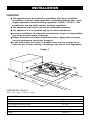
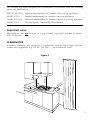
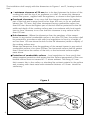
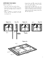
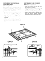
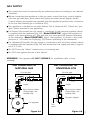
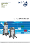
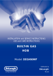
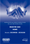
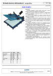
INSTALLATION and SERVICE INSTRUCTIONS
USE and CARE INSTRUCTIONS
BUILT-IN GAS
HOBS
P70 series
Models: DGHS70W - DGHS70WF
distributed by
DèLonghi
Pty Ltd
Dear Customer,
Thank you for having purchased and given your
preference to our product.
The safety precautions and recommendations reported
below are for your own safety and that of others. They
will also provide a means by which to make full use of
the features offered by your appliance.
Please keep this booklet in a safe place. It may be
useful in future, either to yourself or to others in the
event that doubts should arise relating to its operation.
This appliance must be used only for the task it has
explicitly been designed for, that is for cooking
foodstuffs. Any other form of usage is to be considered
as inappropriate and therefore dangerous.
The manufacturer declines all responsibility in the
event of damage caused by improper, incorrect or
illogical use of the appliance or be faulty installation.
PRODUCT LABEL
2
IMPORTANT PRECAUTIONS AND RECOMMENDATIONS FOR
USE OF ELECTRICAL APPLIANCES
Use of any electrical appliance implies the necessity to follow a series of fundamental
rules. In particular:
■ Never touch the appliance with wet hands or feet;
■
do not operate the appliance barefooted;
do not allow children or other incapable people to use the appliance
without supervision.
The manufacturer cannot be held responsible for any damages caused by improper,
incorrect or illogical use of the appliance.
■
IMPORTANT PRECAUTIONS AND RECOMMENDATIONS
After having unpacked the appliance, check to ensure that it is not damaged.
In case of doubt, do not use it and consult your supplier or a professionally qualified
technician.
Packing elements (i.e. plastic bags, polystyrene foam, nails, packing straps, etc.) should
not be left around within easy reach of children, as these may cause serious injuries.
■ Do not attempt to modify the technical characteristics of the appliance as
this may become dangerous to use.
■ Do not carry out cleaning or maintenance operations on the appliance
without having previously disconnected it from the electric power supply.
■ After use, ensure that the knobs are in off position.
■
■
■
■
■
Do not allow children or other incapable people to use the appliance
without supervision.
During and after use of the hob, certain parts will become very hot. Do not
touch hot parts.
Keep children away from the cooker when it is in use.
Some appliances are supplied with a protective film on steel and aluminium
parts. This film must be removed before using the appliance.
The manufacturer declines all liability for injury to persons or damage to
property caused by incorrect or improper use of the appliance.
3
INSTALLATION
CAUTION:
■
■
■
■
■
■
This appliance must be installed in accordance with these installation
instructions, local gas fitting regulations, municipal building codes, water
supply regulations, electrical wiring regulations, AS5601 / AG 601 - Gas
Installations and ony other relevant statutory regulations.
This appliance shall only be serviced by authorized personnel.
This appliance is to be installed only by an authorised person.
Incorrect installation, for which the manufacturer accepts no responsibility,
may cause personal injury of damage.
Always disconnect the cooker from mains power supply before carrying
out any maintenance operations or repairs.
In the room where the cooker is installed, there must be enough air to
allow the gas to burn correctly, according to the current local regulations.
Figure 1
500
680
60
200
0
48
560
0
–2
0
–2
DIMENSIONS (Table 2):
(Note: Also refer to Figure 1 side)
4
General Dimensions
Width
Depth
Depth Below Mounting Surface
Cut-out Dimensions
Width
Depth
680 mm
500 mm
33,7 mm
560 mm
480 mm
0
–2
0
–2
This cooktop has been designed and constructed in accordance with the following
codes and specifications:
AGA101 (AS 4551) Approval Requirements for Domestic Gas cooking appliances
AS/NZS 3350-1
General Requirements for Domestic electrical appliances
AS/NSZ 3350-2-6
Particular Requirements for Domestic electrical cooking appliances
AS/NSZ 1044
Electromagnetic Compatibility Requirements.
Important note:
This appliance shall not be used as a space heater, especially if installed in marine
craft or caravans.
CLEARANCES:
Installation clearances and protection of combustible surfaces shall comply with the
current local regulations e.g. AG 601 (AS 5601) - Gas Installations code.
200 mm
min
750 mm
450 mm
Figure 2
in
mm
60 m
500 mm
5
The installation shall comply with the dimensions in Figures 1 and 2, bearing in mind
that:
■
A minimum clearance of 20 mm has to be kept between the bottom of the
cooking hob and the top of an appliance or a shelf. To ensure this clearance
mount the spacers, supplied with the appliance, as shown in the figure below.
■
Overhead clearances - In no case shall the clearance between the highest
part of the hob and a range hood be less than 600 mm, or for an overhead
exhaust fan, 750 mm. Any other downward facing combustible surface less
than 600 mm above the highest part of the hob shall be protected for the full
width and depth of the cooking surface area in accordance with local regulations in force. However, in no case shall this clearance to any surface be less
than 450 mm.
■
Side clearances - Where the dimension from the periphery of the nearest
burner to any vertical combustible surface is less than 200 mm, the surface shall
be protected in accordance with with local regulations in force to a height of
not less than 150 mm above the hob for the full dimension (width or depth) of
the cooking surface area.
Where the dimensions from the periphery of the nearest burner to any vertical
combustible surface is less than 200mm, the horizontal surface shall be greater
than 10mm below the surface of the hob, or the horizontal surface requirement above.
■
Protection of combustible surfaces - Local regulations in force specify that
where required protection shall ensure that the surface temperature of the combustible surface does not exceed 65 °C above ambient. The fixing of 5 mm
thick ceramic tiles to the surface or attaching fire resistant material to the surface
and covering with sheet metal with minimum thickness of 0.4mm should be
satisfactory.
20 mm
Figure 3
6
APPLYING THE SEALS
(Refer to Figures 4):
– Turn the cooker top upside down.
– Spread the longer seal “A” around the
left, rear and right sides as shown in
figure 4a.
– With a cutter or a scissors cut the
excess seal “C” and retain it for next
use (figure 4b)
Figure 4a
Fig. 4b
seal C
seal A
– Spread the seal “B” around the left,
front and right edges of the cooker
top as shown in figure 4c.
– Spread the seal “C” along the rear
edge of the cooker top as shown in
figure 4d. Making sure that the beginning and the end overlap at the seal
“B” (see figure 4e).
Figure 4c
seal C
Fig. 4d
seal B
Figure 4e
seal C
seal B
NT
FRO
seal A
7
FASTENING THE INSTALLATION BRACKETS
FASTENING THE COOKER
TOP (Refer to Figures 5):
(Refer to Figures 5):
– Insert the cooker top into the hole
and position it correctly.
– Adjust the position of the brackets “F
and R” and tighten screws “B” to
block the cooker top firmly in position.
– With a sharp cutter or trimmer knife
trim the excess sealing material
around the edge of the cooker top.
Each cooker top is provided with an
installation kit including brackets and
screws for fastening the top to fixture
panels from 2 to 4 cm thick.
– Turn the cooker top upside down and
fasten the brackets “F and R” to the
appropriate socket holes, without
tightening the screws “B” for the
moment.
– Make sure that the brackets are fastened as shown in figure 5a, 5b and
5c.
Figure 5a
R
R
F
NT
FRO
F
Figure 5b
Rear side
Figure 5c
Front side
seal C
B
B
F
40 mm max.
40 mm max.
20 mm min.
8
R
20 mm min.
seal A
seal A
GAS SUPPLY:
■
The connection must be executed by an authorised person according to the relevant
standards.
■
Before connecting the appliance to the gas main, mount the brass conical adaptor
onto the gas inlet pipe, upon which the gasket has been placed (figures 6a-6b).
Conical adaptor and gasket are supplied with the appliance (packed with conversion
kit for use with Natural gas or Universal LPG).
This appliance is suitable for use with Natural Gas or Universal LPG. (Check the “gas
type” sticker attached to the appliance).
■ For Natural Gas models the gas supply is connected to the pressure regulator which
is supplied with the appliance (fig. 6a). Model DGHS70W: adjust the regulator to
obtain a test point pressure of 1 kPa with the two semi-rapid (SR) burners operating
at the maximum. Model DGHS70WF: adjust the regulator to obtain a test point
pressure of 1 kPa with the Triple-ring (TR) burner operating at the maximum.⁄
■ For Universal LPG models the gas supply is connected to the test point adaptor which
is supplied with the appliance (fig. 6b) and ensure that the supply pressure is regulated to 2.75 kPa.
■
■
Do NOT force the ”elbow“ rotation prior to loosening nut.
■
Do NOT over tighten the nut at the ”elbow“.
WARNING, This appliance IS NOT SUITABLE for installation with a hose
assembly.
Gas connection for
NATURAL GAS
Gas connection for
UNIVERSAL LPG
Gas inlet pipe
Gas inlet pipe
Test
point
Gasket
Gasket
Brass conical adaptor
Brass conical adaptor
(Thread tight: use
suitable seal)
(Thread tight: use
suitable seal)
Test point adaptor
Gas regulator
Test
point
Figure 6a
Figure 6b
9
1. After connecting the gas supply, check the piping and connections for leaks using a
soap and water solution. The presence of bubbles indicates a leak, tighten or
replace connections as appropriate.
Warning: Do not use any naked flame to check for leaks.
2. The operation of the appliance MUST be tested before leaving.
3. Adjust the test point pressure or supply pressure to the value which is appropriate
for the gas type.
4. Turn on the appliance gas controls and light each burner. Check for a well defined
blue flame without any yellow tipping. If any abnormality is evident then check that
the burner cap is located properly and the injector nipple is aligned correctly.
5. Check the minimum burner setting by quickly rotating the gas control knob from
the maximum to the minimum position, the flame must not go out. If adjustment is
required carry out the “minimum burner setting adjustment" procedure described at
page 12.
6. If satisfactory performance cannot be obtained, the installer shall check the installation and notify the local gas supply authority for a gas supply problem, or if it is an
appliance problem, our Customer Service Centre should be called to obtain the
nearest authorized Delonghi Service Agent.
7. Where the appliance data plate cannot be easily read with the appliance in the
installed position the duplicate data plate must be attached to adjacent surface and
the duplicate Universal LPG conversion label should also be included where a
Universal LPG conversion has been completed.
TABLE FOR THE CHOICE OF THE INJECTORS
Natural gas
1.0
Test Point Pressure [kPa]
2.75
Injector
Orifice Dia.
Gas
Consumption
Injector
Orifice Dia.
Gas
Consumption
[mm]
[MJ/h]
[mm]
[MJ/h]
Auxiliary (A)
0.85
3.60
0.53
3.60
Medium-speed burner (SR)
1.12
6.30
0.70
6.30
Rapid burner (R)
1.45
10.30
0.91
10.80
Triple-ring burner (TR)
1.65
13.00
0.95
11.90
Fish burner (PS)
1.12
6.30
0.70
6.30
BURNER
10
Universal LPG
CONVERSION PROCEDURE (to convert to Universal LPG)
REPLACING THE INJECTORS
The conversion procedure must be carried out only by an authorised person.
This appliance is suitable for use with Natural gas or Universal LPG (check the “gas
type” sticker attached to the appliance). The nominal gas consumption and injector
size details are provided in table at page 10.
To replace the injectors proceed as follows:
■ Remove pan supports and burners from the cooktop.
■ Using a spanner, remove the injector J (figs. 7a, 7b) and replace it with one
according to the gas type (see tables - page 10).
■ Affix to the appliance the warning label stating that the cooktop has been converted for use with Universal LPG (supplied with the Universal LPG conversion kit.).
A second Universal LPG conversion label should also be affixed to an adjacent surface along with the duplicate data plate.
IMPORTANT
■ If the cooktop is suitable for use with Natural gas and must be converted for
use with Universal LPG, before connecting to gas main remove the appliance
gas regulator and replace with test point adaptor (see fig. 6a, 6b)
■ If the cooktop is suitable for use with Universal LPG and must be converted for
use with Natural gas, before connecting to the gas main remove the appliance
test point adaptor and replace with gas regulator (see figs. 6a, 6b).
NOTE:
Gas regulator and test point adaptor are supplied with the appliance (packed with
conversion kit)
The burners are designed so that regulation of primary air is not required.
Figure 7a
Figure 7b
J
J
11
MINIMUM BURNER SETTING ADJUSTMENT
Check whether the flame spreads to all burner ports when the burner is lit with the
gas tap set to the minimum position. If some ports do not light, increase the minimum
gas rate setting.
Check whether the burner remains lit even when the gas tap is turned quickly from
the maximum to the minimum position. If the burner does not remain lit, increase the
minimum gas rate setting.
The procedure for adjusting the minimum gas rate setting is described below.
For taps with adjusting screw inside the shaft (fig. 8):
✓ using a screwdriver max. diameter 3 mm turn the screw inside the tap shaft until
the flame setting is correct.
For taps with adjusting screw on the body (fig. 9):
✓ using a screwdriver turn screw "A" until the flame setting is correct.
Normally for Universal LPG, fully tighten the adjustment screw.
LUBRICATING THE GAS TAP
If a gas tap is difficult to turn, disassemble it, clean it carefully with petrol and spread
a little high-temperature-resistant grease on it.
These operations must be performed by an Authorized person/Service agent.
Note: Servicing of this appliance is only to be carried out by Authorized Person.
Figure 8
Figure 9
A
12
INSTALLATION
ELECTRICAL REQUIREMENTS
The appliance must be connected to the mains checking that the voltage
corresponds to the value given in the rating plate and that the electrical
cable sections can withstand the load specified on the plate.
■ The plug must be connected to an earthed socket in compliance with safety
standards.
■ If the appliance is supplied without plug, fit a standard plug which is
suitable for the power consumed by the appliance.
■ The wires in the power cable are coloured in accordance with the following
code: Green/Yellow = Earth, Blue = Neutral, Brown = Active.
If the colours of the wires in the power cable to the appliance do not
correspond with the coloured markings identifying the terminals in the
junction terminal, proceed as follows:
1.The wire which is coloured green and yellow must be connected to the
terminal marked E (Earth) or coloured Green.
2.The wire which is coloured blue must be connected to the terminal marked
N (Nuetral) or coloured Black.
3.The wire which is coloured brown must be connected to the terminal
marked L (Live) or A (Active) or coloured Red.
■ The appliance must be connected directly to the mains placing a two pole
switch with minimum opening between the contacts of 3 mm between the
appliance and the mains.
■ The power supply cable must not touch the hot parts and must be
positioned so that it does not exceed 50°C above ambient.
■ Once the appliance has been installed, the switch or socket must always be
accessible.
■ If the supply cord is damaged it must be replaced by the manufacturer or it’s
Service Agent or a similarly qualified person in order to avoid a hazard.
■
N.B. The connection of the appliance to earth is mandatory.
If the installation requires alterations to the domestic electrical system call a qualified electrician.
He should also check that the socket cable section is suitable for the power drawn by
the appliance.
13
Replacing the power cord must be done by a qualified electrician in
accordance with the instructions supplied by the manufacturer and in
compliance with established electrical regulations.
Figure 10a
5 gas models
Figure 10b
4 gas models
CA
CA
CA
N
CA
CA
CA
CA
L
M
L
M
A
A
T
T
PA
N
CA
CA
PA
PA
PA
PA
PA
addition for models with
a gas-lighter incorporated
in the knob
ELECTRIC
DIAGRAMS KEY
(models with electric
ignition)
PA
A
M
T
CA
Figure 10c
5 gas models
PA
PA
PA
addition for models with
a gas-lighter incorporated
in the knob
Ignition switch
Ignition coil
Terminal block
Earth conductor
Spark electrode
Figure 10d
4 gas models
CA
CA
CA
N
CA
CA
L
M
N
CA
CA
A
L
M
A
PA
PA
PA
PA
PA
addition for models with
a gas-lighter incorporated
in the knob
14
CA
CA
* Ignition coil without antidisturb filter.
PA
PA
PA
PA
addition for models with
a gas-lighter incorporated
in the knob
USE and CARE
CAUTION:
■
This appliance must be used only for the task it has explicitly been designed for,
that is for domestic cooking of foodstuffs. Any other form of usage is to be considered as inappropriate and therefore dangerous. Do not use this appliance as
a space heater.
■
Do NOT place combustible materials or products on this appliance at any time.
■
Do NOT spray aerosols in the vicinity of this appliance while it is in use.
■
Before using for the first time, clean the cooktop with warm soapy water.
■
Use the coffee pot support to ensure that small cooking utensils are stable.
■
IMPORTANT NOTE: This appliance shall not be used as a space heater,
especially if installed in marine craft or caravans.
15
GAS HOBS
Figure 11a
Model: DGHS70W
14 13 12 11 10
GAS BURNERS
1.
2.
3.
4.
5.
Right semi-rapid burner (SR)
Rapid burner (R)
Central triple ring burner (TR)
Left semi-rapid burner (SR)
Auxiliary burner (A)
Natural Gas
MJ/h
Universal LPG
MJ/h
6.30
10.30
13.00
6.30
3.60
6.30
10.80
11.90
6.30
3.60
CONTROL PANEL
10.
11.
12.
13.
14.
16
Right semi-rapid burner control knob (1)
Rapid burner control knob (2)
Triple-ring burner control knob (3)
Left semi-rapid burner control knob (4)
Auxiliary burner control knob (5)
■
This appliance is class 3 rated
■
The appliance has a safety valve system fitted (beside every burner there is the “T”
probe as in fig. 16 - not confuse with the “S” electrode of the electronic ignition) the
flow of the gas will stopped if and when the flame should accidentally go out.
■
The cooktop is provided with electric gas-lighting device, beside flame
mum aperture or max gas flow - there is the ★ symbol).
- maxi-
Figure 11b
Model: DGHS70WF
13 12 11 10
GAS BURNERS
1.
2.
3.
4.
Semi-rapid burner (SR)
Rapid burner (R)
Fish burner (PS)
Triple ring burner (TR)
Natural Gas
MJ/h
Universal LPG
MJ/h
6.30
10.30
6.30
13.00
6.30
10.80
6.30
11.90
CONTROL PANEL
10.
11.
12.
13.
Semi-rapid burner control knob (1)
Rapid burner control knob (2)
Fish burner control knob (3)
Triple-ring burner control knob (4)
■
This appliance is class 3 rated
■
The appliance has a safety valve system fitted (beside every burner there is the “T”
probe as in fig. 16 - not confuse with the “S” electrode of the electronic ignition) the
flow of the gas will stopped if and when the flame should accidentally go out.
■
The cooktop is provided with electric gas-lighting device, beside flame
mum aperture or max gas flow - there is the ★ symbol).
- maxi17
USING GAS BURNERS
■
Check that the electricity is switched on to allow spark ignition (models with
electric ignition).
■
Make sure that all controls are turned to zero.
■
The gas flow to the burner is controlled by the knobs on the safety taps.
■
You control the flow by turning the knob indicator to line up with the following
symbols:
– Symbol
●
: tap closed (burner off)
– Symbol
: High (maximum)
– Symbol
: Low (minimum)
■
You can control the temperature by the knob to “High” from “Minimum”.
■
To switch off, turn the knob clockwise until you hear the safety click.
■
Note that, if you are using a burner at the minimum setting, you turn the knob
clockwise past the maximum setting before reaching the off position.
Whenever lighting any of the burners produces an abnormal flame, switch that
burner off and relight using the minimum setting.
If after relighting the burner, the flame is still abnormal, turn the burner off and
contact our Customer Service Centre to obtain the nearest authorized Delonghi
Service Agent.
In the case of a mains failure light the burner with a match or lighted taper.
■
■
■
■
Note: When the cooker top is not being used, set the gas knobs to their
closed positions and also close the cock valve on the gas bottle or the main
gas supply line,
Figure 12
18
LIGHTING THE BURNERS
(fitted with safety cut-off valve)
In order to light the burner, you must:
1 – Models fitted with electric lighter incorporated into the burner knobs:
Turn the knob fig. 12 in anti-clockwise direction up to the maximum aperture
(symbol
), push in and hold the knob; this will light the gas.
2 – Wait for about ten seconds after the gas burner has been lit before letting go
of the knob (valve activation delay).
3 – Adjust the gas valve to the desired position.
Important
■
If the burner flame should go out, the safety valve will automatically stop the
gas flow.
■
To re-light the burner, return the knob to the closed ● position, wait for at least
1 minute and then repeat the lighting procedure.
■
N.B. If your local gas supply makes it difficult to light the burner with the knob
set to maximum, set the knob to minimum and repeat the operation.
■
Whenever lighting any of the burners produces an abnormal flame, switch that
burner off and relight using the minimum setting.
■
If after relighting the burner, the flame is still abnormal, turn the burner off and
contact our Customer Service Centre to obtain the nearest authorized Delonghi
Service Agent.
19
COOKING HINTS FOR GAS HOBS
■
The burner must be chosen according to the diameter of the pans and energy
required.
■
For optimum efficiency use a wok or pan no smaller than 230mm diameter.
Figure 13
do not use pans
with concave or convex bases
Burners
Auxiliary (1)
Semi-rapid
Rapid
Triple ring
Fish burner
Wok
Pan diameter
12 - 14 cm
16 - 24 cm (2)
24 - 26 cm
26 - 28 cm
from 12x30 to 18x38 cm
max 36 cm
(1): with grill for small cookware: minimum diameter 6 cm
(2): front right burner, maximum diameter 22 cm
20
■
Saucepans with handles which are excessively heavy, in relationship to the
weight of the pan, are safer as they are less likely to tip.
■
Pans which are positioned centrally on burners are more stable than those
which are offset.
■
It is far safer to position the pan handles in such a way that they cannot be
accidentally knocked.
■
When deep fat frying fill the pan only one third full of oil.
■
DO NOT cover the pan with a lid and DO NOT leave the pan unattended.
■
In the unfortunate event of a fire, leave the pan where it is and turn off all controls.
■
Place a damp cloth or correct fitting lid over the pan to smother the flames.
■
DO NOT use water on the fire.
■
Leave the pan to cool for at least 30 minutes.
GRILL FOR SMALL COOKWARE
■
(fig. 14)
Put it on the auxiliary burner (the smallest) grid when small cookware is being
used to prevent the cookware from tipping over.
Figure 14
21
CORRECT USE OF TRIPLE-RING BURNER
■
The flat-bottomed pans are to be placed directly onto the pan-support.
■
To use the WOK, you must place the wok stand in the CORRECT position as
shown in fig. 15.
Figure 15
WRONG
22
CORRECT
Cleaning and Maintenance
GENERAL TIPS
■
■
■
■
■
Before cleaning the hob switch it off and wait for it to cool down.
Clean with a cloth, hot water and soap or liquid detergent.
Do not use products which are abrasive, corrosive or chlorine based.
Do not use steel pads.
Do not leave acid or alkaline substances (vinegar, salt, lemon juice, etc.) on
the hob.
ENAMELLED PARTS
■
■
All the enamelled parts must be washed only with a sponge with soapy
water or other non-abrasive products.
Dry carefully.
STAINLESS STEEL HOB
■
■
■
Clean with special products which are available on the market.
Dry preferably with chamois leather.
Note: regular use will cause discolouring around the burners, because of
the high flame temperature.
BURNERS AND GRIDS
■
■
■
■
These pieces can be removed and washed with suitable products.
After cleaning burners and spreaders dry them well and replace them
correctly.
In appliances with electric ignition keep the electrode clean so that the
sparks always strike.
Note (models with electric ignition): To avoid damage to the electric
ignition do not use it when the burners are not in place.
GAS TAPS
■
■
Regular lubrication of the gas taps must only be performed by Authorized
person.
If the gas taps are not working properly, call our Customer Service Centre to
obtain the nearest Authorized Delonghi Service Agent.
23
CORRECT POSITIONING OF THE BURNERS
■
It is very important to check that spreader “F” and cap “C” of the burner (see
Figures 16 and 17) are perfectly in place because if they move out of place
serious problems could arise.
■
Make sure that electrode "S" (Fig. 16) is kept clean so that the sparks always
strike.
■
Make sure that probe “T” (fig. 16) next to each burner is kept clean to ensure
correct operation of the safety valves.
■
Both the probe and ignition plug must be very carefully cleaned.
■
Note: To avoid damage to the electric ignition do not use it when the
burners are not in place.
Figure 16
Figure 17
C
F
T
S
24
CORRECT POSITIONING OF THE TRIPLE-RING BURNER
■
The triple ring burner must be correctly positioned (see fig. 20); the burner rib
must be located in position as shown by the arrow (see fig. 18).
■
The burner correctly positioned must not rotate (fig. 19).
■
Then position the cap “A” and the ring “B” (fig. 19).
Figure 18
Figure 20
Figure 19
A
B
25
CORRECT POSITIONING OF THE FISH BURNER
(model DGHS70WF)
■
This burner must be correctly positioned as shown in the figure 21.
Figure 21
S
T
26
SERVICE AND MAINTENANCE
If the ignition spark fails to ignite or does not light the gas, check the following
items before calling our Customer Service Centre to obtain the nearest Authorised
Delonghi Service Agent:
■
■
■
Burner is reassembled and located correctly.
Spark electrode and white ceramic are clean and dry.
240 VAC power supply is connected.
Contact the local gas utility or our Customer Service Centre to obtain the nearest
Authorized Delonghi Service Agent.
■
■
■
You can smell gas when all burners are turned on.
The burners do not remain alight at the minimum marked setting.
The burner flame is yellow or emits an unusual odour.
Note that a bi-annual inspection of the appliance by an authorized service agent
or your local gas utility will ensure many years of trouble free operation of your
appliance.
Servicing the appliance:
Service may be obtained by contacting our Customer Service Centre to locate the
nearest Authorised Delonghi Service Agent:
LUBRICATION OF THE GAS TAPS
If the gas tap becomes stiff, it is necessary to dismantle it carefully and clean it with petroleum
spirit. Specialist high temperature resistant grease should be used to lubricate the tap before
replacing.
The operations must be carried out by an authorised person/service agent.
Figure 22
Gas taps fitted with
flame failure device
27
Descriptions and illustrations in this booklet are given as simply indicative. The manufacturer reserves the right,
considering the characteristics of the models described here, at any time and without notice, to make eventual
necessary modifications for their construction or for commercial needs.
Cod. 1102193 - ß6