1
SECTION II
AIRPLANE AND SYSTEMS
MODEL 560
HYDRAULIC
GENERAL
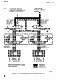
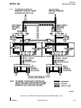
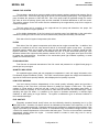
The Main hydraulic system is an open-center type system. Two engine-driven pumps (one on each
engine) supply a continuous flow of hydraulic fluid as long as engine(s) is operating. A reservoir stores fluid
for the various hydraulically operated components. The reservoir is a boot-strap type and performs similar
to a hydraulic accumulator by maintaining potential pressure on system. A solenoid operated bypass valve
controls open center operation of the system. In a no-pressure-demand condition, the bypass valve is deenergized open, allowing fluid to free-flow from pressure to return. In a pressure demand condition, the
bypass valve is energized closed and pressure is routed to a selected system/component. A relief valve
limits hydraulic system pressure to 1500 PSI (10,342 kPa). A relief valve is installed in parallel with the
bypass valve on a hydraulic sub-panel.
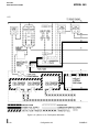
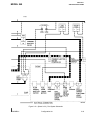
Other main system components include two pressure filters, one located in left engine pump pressure
line and one in right pump pressure line. A third return filter is located in the return line to hydraulic
reservoir. Two firewall hydraulic shutoff valves are motorized electrically closed or open. Either shutoff
valve may be closed during an engine fire, stopping flow of fluid to the engine pump selected. Ground
service connections are located at the tailcone lower exterior surface.
A flow switch check valve is incorporated in each pressure line from engine hydraulic pumps. Check
valves prevent fluid flow from one engine pump to other. Flow switches provide an indication on the
annunciator panel when low/no-flow occurs from respective engine pump.
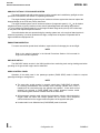
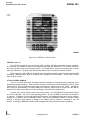
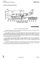
RESERVOIR
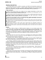
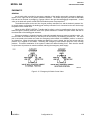
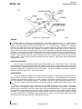
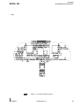
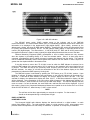
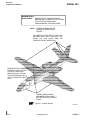
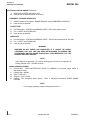
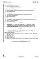
The fluid for the system is contained in an accumulator-type reservoir located in the aft tailcone area.
The quantity of fluid is shown by a plunger-type sight gage located on the aft side of the reservoir. The
refill, low, full, and overfull indications correspond to 0.3, 0.8, 0.9, and 1.5 gallons, respectively. A
microswitch attached to the accumulator plunger will activate an amber LO HYD LEVEL annunciator panel
light any time the fluid level drops below the low position. Servicing requires equipment capable of
delivering hydraulic fluid under pressure. Bleeding or relieving an overfill condition is accomplished by
opening a relief valve located on the reservoir. Relieved excessive fluid is drained overboard through the
underbelly vent mast. Any internal leakage is collected and drained through an overboard vent line into the
underbelly vent mast.
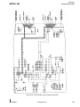
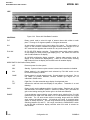
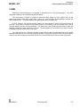
Figure 2-11 Hydraulic Reservoir
I
2-20
Configuration AA
56OMB-01