1
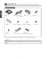
Deutsch
Excellent Sound Quality CD/Memory Stick Receiver with MP3/WMA
English
MODEL
Superb Sound Quality CD Receiver with MP3
MODEL
Español
INSTALLATION MANUAL
Italiano
Contents
Before
installation
Installation
Components
2
For your safety in using the CD8445E or CD5425E
3
Names and functions of terminals
4
System connection example
6
Installing the main unit
7
Nederlands
Connections
Français
Be sure to read this installation manual thoroughly before carrying out installation and making
connections. If installation methods or non-standard parts that are not specified in this installation
manual are used, accidents or injury may result.
Professional installation is recommended, contact the place of purchase to schedule an appointment.
After reading the owner's manual and the installation manual thoroughly, keep them in a safe place for
later reference.
To dealers:
Give this installation manual to the customer after installation and connections have been completed.
Svenska
Deutsch
Components
Check that all of the following components are present
Main unit components
English
1 Main unit x 1
2 Interconnecting cable
3 Mounting sleeve
(Power and speaker connector)
(16P) x 1
Español
5 Bezel
6 Hex-head bolt
x1
Français
9 Bushing
7 Flat head screw
(Red:M5x8) x 4
10 Case
x1
4 Side bracket
x1
x2
8 Stud bolt
(Red:M5x8) x 4
*
x1
11 Remote control
(For detachable panel)x 1
(Only included with CD8445E) x 1
Italiano
*The remote control is only included with the CD8445E. It is not included with the CD5425E.
Tip
Nederlands
When installing the main unit, some vehicle models may require the use of items that need to be
obtained separately such as a power supply adaptor cable, radio antenna adaptor cable or mounting
bracket.
Svenska
-2-
Warning and caution signs, illustrated below, are posted throughout this manual as well as on the CD8445E
and CD5425E. They show safe and correct ways to handle the product so as to prevent personal injury to
you and others and to avoid damage to property.
Before reading through the manual, take time to read through and learn the important information listed in
this section.
This sign indicates a situation in which incorrect handling through disregard of a sign
might result in personal injury or may result solely in damage to property.
Tip
This section contains information that can help to prevent problems and
damage to the unit, and also contains other useful information.
• Air bags are vital safety equipment. Never install equipment
installed in a vehicle with a 12V negative earth electrical
system. Any other installation may cause a fire or other
severe damage to the equipment and the vehicle.
in a way which will alter air bag wiring or interfere with air
bag deployment. Air bags must function properly in the
event of an accident.
• When installing equipment, do not remove or alter existing
• For your protection, never use a power drill without safety
vehicle fasteners, including nuts, bolts, screws, clips, and
fittings. Never detach, move or alter existing vehicle wiring,
including electrical grounds and straps. Alteration of existing
vehicle components may make the vehicle unsafe to
operate.
glasses or goggles. Debris or broken drill bits may cause
severe eye injuries, including blindness.
Español
• This equipment requires 12V DC and should only be
English
This sign indicates a situation in which incorrect handling through disregard
of a sign might result in death or serious personal injury.
Deutsch
For your safety in using the CD8445E or CD5425E
• Use electrical tape to insulate the ends of all wires, even if
• Do not disassemble or alter this equipment. Accidents, fires
• Before installation, remove the negative
battery terminal
to prevent shocks, electrical arcing, fires, and damage to
vehicle wiring and the equipment you are installing.
or shocks may result.
• Always replace fuses with fuses of identical capacity and
• Secure wiring with tape or plastic ties so that wires do not
characteristics. Never use a higher-rated fuse than the
original. Using the wrong type of fuse may cause a fire or
severe damage.
interfere with vehicle operation, including brake pedal, gear
shifter and steering. Position wires so that they will not be
rubbed, abraded, or damaged by moving vehicle
components, including power seats.
• Do not modify this system for use other than that specified
never supply power to installed equipment in a way which
will overload the capacity of an existing vehicle circuit.
Never leave a power supply wire or connection uninsulated.
Always install supplied fuses, circuit breakers, and relays
• Do not block the fan, heat sink or vents for this unit. When
experience. Professional installation is recommended.
Consult with your dealer or a professional installer. Incorrect
wiring may damage the equipment or interfere with safe
vehicle operation.
fan, heat sink or vent are blocked, the interior overheats,
and fires may result.
• Connect as specified in the installation manual. If not
connected normally, fires or accidents may result.
• Use only the accessory parts as specified. Using other parts
• When installing in vehicles equipped with air bags, check
may cause damage to the equipment or cause parts to fall
or fly off the equipment.
the manufacturer's cautions regarding operation before
operating. Airbags may not operate properly.
• Do not install the unit in places where it may get dew
• Carry out the wiring such that cords are not pinched by
condensation on (around the air conditioning hose, etc.),
come in contact with water, or in conditions of high
moisture, dust or oily smoke. If water, moisture, dust or oily
smoke enters this unit, smoke, fires or malfunctions may
result.
movable parts such as seat rails, and screw parts of the
vehicle body. Accidents, fires and shocks may result from
disconnection and electrical shorts.
Nederlands
• Wiring and installing this equipment requires expertise and
Italiano
herein. Also, do not deviate from the installation procedures
described herein; Eclipse will not be held liable for damages
including, but not limited to serious injury, death or property
damage resulting from installations that enable unintended
operation.
• To avoid equipment and vehicle damage, including fire,
Français
not used. Proper insulation prevents arcs, shocks and fires.
• Carry out the wiring such that the cord does not make
• Avoid installing in places where it cannot be fastened
• Avoid hot surfaces when wiring equipment. High
temperatures may damage wiring, causing shorts, arcing
and fires.
• When changing the installation location for this equipment,
• Do not install in places with direct sunlight or where it will be
please consult the dealer where you bought it for safety
reasons. Expertise is necessary for removal and
installation.
hit directly by hot air from the heater. This may increase the
temperature of the interior of this equipment, resulting in
fires and malfunctions.
-3-
Svenska
contact with metal parts. The cord may be damaged by
contact with metal parts, resulting in fire and shocks.
securely or where there are strong vibrations. Also, if you
installed the unit with double-sided tape, first wipe away dirt
and wax from the installation area. Otherwise, the unit may
come loose due to vibration while driving, causing problems
for driving and resulting in traffic accidents or injuries.
Deutsch
Names and functions of ter minals
English
• Never cut the insulation on the power cable or use it to power any other equipment. If the rated current
capacity of the power cable is exceeded, fire and electric shocks may result.
• The cables should be secured with tape or a similar securing method to prevent any obstructions while
driving. If they get wound or entangled around components such as the steering wheel, shifting lever,
or brake pedal, accidents may result.
• If removing the end of the cord to connect to another cord, be sure to wrap PVC tape or a similar wire
insulating method around the connection to insulate it. If the connection is not insulated, fire or
accidents may result.
Español
1 MAIN UNIT
ANTENNA PLUG
Français
E
D
16P
C
A
B
2 INTERCONNECTING CABLE
(Power and speaker connector)
Italiano
Tip*1
4
3
1
2
TO VEHICLE-SIDE
CONNECTOR
Tip*1
• The positions of the B+ and ACC pins on the connector may vary
depending on the vehicle. In such cases, replace the end of the
connector. Ask your dealer for details on connector pin positions.
Nederlands
Svenska
Tip
• This illustration shows the CD8445E. The CD5425E differs slightly from this illustration.
• Refer to page 5 for details on the wire colours and connection points for interconnecting cables
• Refer to page 5 for details on connection points
A to E for the main unit cables and
terminals.
-4-
2
.
1
2
Antenna power supply (Blue)
Connect to the automatic-antenna control terminal of the vehicle.
2
Control power supply (Blue/White)
Deutsch
Wire colours and connection points for connection cables
Connect the control terminal for the external amplifier, etc.
Cellular phone mute Wire (Pink)
Connect to the earth output terminal on a mobile phone.
4
Earth (Black)
Connect where good body earthing is available.
Main unit connections
E-LAN terminal (13P)
B
Front line-out terminal
Connect to the E-LAN terminal of the CD changer, etc.
Connect to the RCA connector of an external amplifier.
Rear line-out terminal
C
Connect to the RCA connector of an external amplifier.
D
Line-out terminal (Non fader)
Español
A
English
3
This is used for non fader output. It can be used as a sub-woofer terminal if a separate amplifier with
a low bass filter is connected.
AUX in terminals (CD8445E only)
Connect if using together with portable audio equipment that is sold separately.
* If the output from the connected equipment is via a mini plug, it will need to be converted to RCA.
- If installing to a vehicle with no ACC position -
Français
E
Tip
Italiano
• If installing to a vehicle with no ACC position, be sure to explain the following to the customer when
handing back the vehicle.
“When getting out of the vehicle, be sure to press the [PWR] button on the main unit for 2
seconds or more while the power is still on, and then turn off the power.” If they forget to turn off
the power, the battery will be drained.
- Vehicle connections • You will need to purchase the necessary component adapter cable for the vehicle so that the power
supplies can be utilised. (Contact the dealer for further details.)
Nederlands
Tip
Svenska
-5-
Deutsch
System connection example
English
• Never cut the insulation on the power cable or use it to power any other equipment. If the rated current
capacity of the power cable is exceeded, fire and electric shocks may result.
• The cables should be secured with tape or a similar securing method to prevent any obstructions while
driving. If they get wound or entangled around components such as the steering wheel, shifting lever,
or brake pedal, accidents may result.
• If removing the end of the cord to connect to another cord, be sure to wrap PVC tape or a similar wire
insulating method around the connection to insulate it. If the connection is not insulated, fire or
accidents may result.
Tip
Español
• Install and connect all of the peripheral units before connecting them to the main unit.
• Do not remove any of the protective caps (RCA, etc.) unless in use.
1 MAIN UNIT
ANTENNA PLUG
Français
l
na
ter
x
e
ing
) n us
A
e
C
(R wh
UT aps
P
c
N
g
X I ve
sin
AU emo o)
R
nu
A
e
(r udi
E
h )
a
T R ER ps w fier
ON FADe ca mpli
R
F N ov al a
NO(rem tern
ex
16P
13P
Italiano
ck
Bla
DIN CABLE
(Supplied with CD changer)
Nederlands
TO
(Pe BA
rm TTE
an R
en Y+
t S 12
up V
ply
)
k
Pin
e
Blu
TO EARTH
hite
E
UT )
e/W
u
l
M
TO VEHICLE-SIDE
B
ly
L
TE Supp
CONNECTOR
(
ER
Y
W
O
LA
P
E
2
INTERCONNECTING
F
R
CABLE
NA
DO
EA ly)
EN
(Power and speaker
L
T
N
N
p
connector)
-O (Sup
RA
N
E
R
W
TU IFER
PO
TO PL
DIGITAL OUT
TO
AM
(Do not remove cap)
Ye
llow
13P
2P
ck
Bla
Svenska
TO EARTH
CH3083
(sold separately)
POWER CONNECTOR CABLE
(Supplied with CD changer)
-6-
Deutsch
Installing the main unit
- Installation angle -
Tip
Front
30˚ or less
Level (reference)
Tip
Insert the mounting sleeve into the opening in the
vehicle dashboard or console box.
2
Use a screwdriver or the like to bend the tabs in
the mounting sleeve to secure the mounting
sleeve.
3
Attach the side brackets to the main unit using
flathead screws.
Bend the mounting
tabs.
3 Mounting sleeve
1
Main unit
7 Flat head
screws
(Red:M5 x 8)
x2
Tip
4
Mount the stud bolt to the main unit.
5
Insert the main unit into the mounting sleeve until
it locks in place.
6
Fasten the rear of the main unit.
7
Install the bezel on the main unit.
4 Side brackets
Metal of vehicle
Dashboard or console box
9 Bushing
• Be careful not to forcefully push on the main unit's
display or buttons during installation. This may
result in damage to the main unit.
• This installation method is only one example.
When installing the main unit to the vehicle, be
sure to as the place of purchase for information
on what installation method to use.
-7-
8 Stud bolt
3 Mounting sleeve
5 Bezel
Svenska
Tip
Nederlands
Be sure to use the supplied accessory mounting
screws (Red:M5 x 8) as the mounting screws. If
any other screws are used, they may damage the
inside of the unit.
Italiano
1
Dashboard or console box
Français
• Carefully bind any excess length of cord that is
connected to the main unit and secure it to an
area of empty space in the vehicle so that it does
not move around or get caught in the main unit or
vehicle-side equipment. If the cords are not
handled correctly, operating problems or shortcircuits may occur, and this may result in the
danger of fire or other accidents.
• Connect all cables before installing the main
unit.
Español
- Main unit installation example (If installing the main unit using the mounting sleeve) -
English
To maintain proper function, the unit must be
mounted at less than 30 degrees. If the angle is in
excess of 30 degrees, CD skipping or ejection may
occur.
Deutsch
- Main unit installation example (If installing the main unit using the side brackets of the vehicle) -
Tip
English
• Carefully bind any excess length of cord that is
connected to the main unit and secure it to an
area of empty space in the vehicle so that it does
not move around or get caught in the main unit or
vehicle-side equipment. If the cords are not
handled correctly, operating problems or shortcircuits may occur, and this may result in the
danger of fire or other accidents.
• Connect all cables before installing the main
unit.
Español
1
Remove the pocket and any other accessories
from the centre cluster to make room for the main
unit.
2
Remove the mounting brackets for the pocket.
3
Attach the brackets to the main unit.
Centre cluster panel
Pocket, etc
Mounting bolts
1
Main unit
Tip
Be sure to use the supplied accessory mounting
screws (Red:M5 x 8) as the mounting screws. If
any other screws are used, they may damage the
inside of the unit.
6 Hex-head bolt
(Red:M5 x 8) x 4
Français
Screw
x4
Pocket
4
Install the main unit in the vehicle.
Mounting bracket
Tip
Italiano
• Be careful not to forcefully push on the main unit's
display or buttons during installation. This may
result in damage to the main unit.
• This installation method is only one example.
When installing the main unit to the vehicle, be
sure to as the place of purchase for information
on what installation method to use.
Nederlands
Svenska
-8-
Hex-head bolt
6 (Red:M5 x 8) x 4
7 Flat head
screw
(Red:M5x8) x 4
Select the screws in accordance with the shapes
of the screw holes in the mounting bracket.