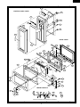
1
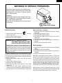
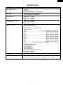
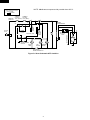
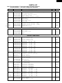
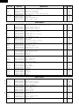
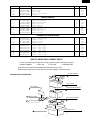
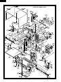
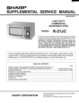
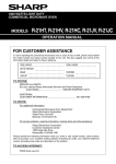
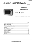
R-21JV
SUPPLEMENTAL SERVICE MANUAL
S3908R21HVP//
LIGHT DUTY
COMMERCIAL
MICROWAVE OVEN
1000W/ R-21JV
ON DEF NO. X2
CHECK
MODEL
COMM
ERCIA
L MICR
O
R-21JV
WAVE O
VEN
In the interest of user-safety the oven should be restored to its original
condition and only parts identical to those specified should be used.
WARNING TO SERVICE PERSONNEL: Microwave ovens contain circuitry capable of producing very high voltage and
current. Contact with the following parts may result in a
severe, possibly fatal, electrical shock. (High Voltage Capacitor, High Voltage Power Transformer, Magnetron, High Voltage Rectifier Assembly, High Voltage Harness etc..)
This is a supplemental Service Manual for Model R-21JV. This model is quite similar to base
model R-21HV. Use this supplemental manual together with the Base Model Service Manual
(Reference No. is S7814R21HTP//) for complete operation, service information, etc..
TABLE OF CONTENTS
Page
PRECAUTIONS TO BE OBSERVED BEFORE AND DURING SERVICING TO
AVOID POSSIBLE EXPOSURE TO EXCESSIVE MICROWAVE ENERGY ................... INSIDE FRONT COVER
BEFORE SERVICING ...................................................................................................... INSIDE FRONT COVER
WARNING TO SERVICE PERSONNEL ................................................................................................................ 1
FOREWORD AND WARNING ............................................................................................................................... 2
PRODUCT SPECIFICATIONS .............................................................................................................................. 3
SCHEMATIC DIAGRAM ........................................................................................................................................ 4
PARTS LIST .......................................................................................................................................................... 5
PACKING AND ACCESSORIES ........................................................................................................................... 7
SHARP CORPORATION
This document has been published to be used for after
sales service only.
The contents are subject to change without notice.
R-21JV
PRECAUTIONS TO BE OBSERVED BEFORE AND
DURING SERVICING TO AVOID POSSIBLE
EXPOSURE TO EXCESSIVE MICROWAVE
ENERGY
(a) Do not operate or allow the oven to be operated with the door open.
(b) Make the following safety checks on all ovens to be serviced before activating the magnetron or other
microwave source, and make repairs as necessary: (1) interlock operation, (2) proper door closing, (3)
seal and sealing surfaces (arcing, wear, and other damage), (4) damage to or loosening of hinges and
latches, (5) evidence of dropping or abuse.
(c) Before turning on microwave power for any service test or inspection within the microwave generating
compartments, check the magnetron, wave guide or transmission line, and cavity for proper alignment,
integrity, and connections.
(d) Any defective or misadjusted components in the interlock, monitor, door seal, and microwave
generation and transmission systems shall be repaired, replaced, or adjusted by procedures described
in this manual before the oven is released to the owner.
(e) A microwave leakage check to verify compliance with the Federal Performance Standard should be
performed on each oven prior to release to the owner.
BEFORE SERVICING
Before servicing an operative unit, perform a microwave emission check as per the Microwave
Measurement Procedure outlined in this service manual.
If microwave emissions level is in excess of the specified limit, contact SHARP ELECTRONICS
CORPORATION immediately @1-800-237-4277.
If the unit operates with the door open, service person should 1) tell the user not to operate the oven
and 2) contact SHARP ELECTRONICS CORPORATION and The Food and Drug Administration's
Center for Devices and Radiological Health immediately.
Service personnel should inform SHARP ELECTRONICS CORPORATION of any certified unit found
with emissions in excess of 4mW/cm2. The owner of the unit should be instructed not to use the unit
until the oven has been brought into compliance.
R-21JV
WARNING TO SERVICE PERSONNEL
Microwave ovens contain circuitry capable of producing very high voltage and current, contact with
following parts may result in a severe, possibly
fatal, electrical shock.
(Example)
High Voltage Capacitor, High Voltage Power Transformer, Magnetron, High Voltage Rectifier Assembly, High Voltage Harness etc..
Read the Service Manual carefully and follow all
instructions.
Don't Touch !
Danger High Voltage
When the testing is completed,
1. Disconnect the power supply cord, and then remove
outer case.
2. Open the door and block it open.
3. Discharge high voltage capacitor.
4. Reconnect the leads to the primary of the power
transformer.
5. Reinstall the outer case (cabinet).
6. Reconnect the power supply cord after the outer case is
installed.
7. Run the oven and check all functions.
Before Servicing
1. Disconnect the power supply cord
remove outer case.
2. Open the door and block it open.
3. Discharge high voltage capacitor.
, and then
WARNING:RISK OF ELECTRIC SHOCK.
DISCHARGE THE HIGH-VOLTAGE
CAPACITOR BEFORE SERVICING.
The high-voltage capacitor remains charged about 60
seconds after the oven has been switched off. Wait for 60
seconds and then short-circuit the connection of the highvoltage capacitor (that is the connecting lead of the highvoltage rectifier) against the chassis with the use of an
insulated screwdriver.
After repairing
1. Reconnect all leads removed from components during
testing.
2. Reinstall the outer case (cabinet).
3. Reconnect the power supply cord after the outer case is
installed.
4. Run the oven and check all functions.
Whenever troubleshooting is performed the power supply
must be disconnected. It may in, some cases, be necessary
to connect the power supply after the outer case has been
removed, in this event,
1. Disconnect the power supply cord, and then remove
outer case.
2. Open the door and block it open.
3. Discharge high voltage capacitor.
4. Disconnect the leads to the primary of the power
transformer.
5. Ensure that the leads remain isolated from other
components and oven chassis by using insulation tape.
6. After that procedure, reconnect the power supply cord.
Microwave ovens should not be run empty. To test for the
presence of microwave energy within a cavity, place a cup
of cold water on the oven turntable, close the door and set
the power to HIGH and set the microwave timer for two (2)
minutes. When the two minutes has elapsed (timer at zero)
carefully check that the water is now hot. If the water
remains cold carry out Before Servicing procedure and reexamine the connections to the component being tested.
When all service work is completed and the oven is fully
assembled, the microwave power output should be checked
and a microwave leakage test should be carried out.
1
R-21JV
SERVICE MANUAL
LIGHT DUTY
COMMERCIAL
MICROWAVE OVEN
R-21JV
FOREWORD
This Manual has been prepared to provide Sharp Electronics Corp. Service Personnel with Operation and Service
Information for the SHARP MICROWAVE OVEN, R-21JV.
The model R-21JV is quite similar to base model R-21HV (Refer No. is S7814R21HTP//).
It is recommended that service personnel carefully study the entire text of this manual and the base model's manual so
that they will be qualified to render satisfactory customer service.
Check the interlock switches and the door seal carefully. Special attention should be given to avoid electrical shock and
microwave radiation hazard.
WARNING
Never operate the oven until the following points are ensured.
(A) The door is tightly closed.
(B) The door brackets and hinges are not defective.
(C) The door packing is not damaged.
(D) The door is not deformed or warped.
(E) There is no other visible damage with the oven.
Servicing and repair work must be carried out only by trained service personnel.
DANGER
Certain initial parts are intentionally not grounded and present a risk of electrical shock only during servicing.
Service personnel - Do not contact the following parts while the appliance is energized;
High Voltage Capacitor, Power Transformer, Magnetron, High Voltage Rectifier Assembly, High Voltage
Harness;
If provided, Vent Hood, Fan assembly, Cooling Fan Motor.
All the parts marked “*” on parts list are used at voltages more than 250V.
Removal of the outer wrap gives access to voltage above 250V.
All the parts marked “∆” on parts list may cause undue microwave exposure, by themselves, or when they are
damaged, loosened or removed.
SHARP ELECTRONICS CORPORATION
SHARP PLAZA, MAHWAH,
NEW JERSEY 07430-2135
2
R-21JV
SPECIFICATION
ITEM
Power Requirements
Power Output
Case Dimensions
Cooking Cavity Dimensions
(1.0 Cubic Feet )
Control Complement
Oven Cavity Light
Safety Standard
DESCRIPTION
120 Volts
14 Amperes
60 Hertz / Single phase, 3 wire grounded
1000 watts (IEC 705 Test Procedure)
Operating frequency of 2450MHz
Width 20-1/2" (520mm)
Height 12-1/8" (309mm)
Depth 16"
(406mm)
Width 13-7/8" (353mm)
Height 8-1/8" (207mm)
Depth 14-5/8" (370mm)
Touch Control System
Timer (0 - 99 min. 99 seconds)
Microwave Power for Variable Cooking
Repetition Rate;
P-HI .................................................. Full power throughout the cooking time
P-90 .................................................................... approx. 90% of Full Power
P-80 .................................................................... approx. 80% of Full Power
P-70 .................................................................... approx. 70% of Full Power
P-60 .................................................................... approx. 60% of Full Power
P-50 .................................................................... approx. 50% of Full Power
P-40 .................................................................... approx. 40% of Full Power
P-30 .................................................................... approx. 30% of Full Power
P-20 .................................................................... approx. 20% of Full Power
P-10 .................................................................... approx. 10% of Full Power
P-0 .................... No power throughout the cooking time
DOUBLE QUANTITY pad
EXPRESS DEFROST pad
Ten number pads
SELECTATIME pad
STOP/CLEAR pad
SELECATAPOWER pad [R-21HT only]
START pad, SET pad
CHECK pad, SIGNAL pad
Yes
UL Listed
FCC Authorized
DHHS Rules, CFR, Title 21, Chapter 1, Subchapter J, NSF certified
3
R-21JV
NOTE:
SCHEMATIC
NOTE: CONDITION OF OVEN
1. DOOR CLOSED.
2.
.
APPEARED.
THERMAL
THERMAL
CUT-OUT
CUT-OUT
125˚C (OVEN) 145˚C (MAG.)
B1
RY2
MONITOR SWITCH
CONTROL UNIT
PRIMARY
INTERLOCK
RELAY
RY3
CONTROL
RELAY
AC120V
60 Hz
B2
OL
DOOR SENSING
SWITCH
OVEN
LAMP
FM
FAN
MOTOR
AM
ANTENNA
MOTOR
SECONDARY
INTERLOCK SWITCH
Figure O-1 Oven Schematic-OFF Condition
4
CAPACITOR
0.94 µF
2400V
MAGNETRON
POWER
TRANSFORMER
A7
A3
RECTIFIER
MONITOR
FUSE 20A
Indicates components with potential above 250 V.
R-21JV
PARTS LIST
Note: The parts marked “∆” may cause undue microwave exposure.
The parts marked “*” are used in voltage more than 250V.
REF. NO.
PART NO.
DESCRIPTION
Q'TY
CODE
1
1
1
1
1
1
1
1
1
1
1
1
1
1
1
AK
AF
AH
AV
AV
AV
AU
AG
AG
AY
AQ
AP
AK
BM
BN
1
1
1
2
1
AX
AS
AQ
AC
AF
1
1
1
1
1
1
1
1
1
1
1
2
1
1
1
1
1
1
4
2
1
1
1
1
1
1
1
1
1
1
1
2
3
1
1
1
1
1
9
2
9
1
1
BK
AC
AB
AF
AE
AA
AA
AA
AA
AA
AA
AA
AA
AA
AA
AA
AA
AD
AB
AA
AB
AA
AV
AL
AE
AS
AE
AA
AB
AC
AB
AC
AA
AA
AA
AA
AA
AA
AA
AA
AA
AL
AN
ELECTRIC PARTS
*
*
*
*
∆*
1- 1
1- 2
1- 3
1- 4
1- 5
1- 6
1- 7
1- 8
1- 9
1-10
1-11
1-12
1-13
1-14
1-15
FFS-BA015WRK0
QSW-MA051WRE0
QSW-MA135WRE0
FACCDA078WRE0
FH-DZA084WRK0
RC-QZA242WRE0
RMOTEA376WRE0
QFSHDA009WRE0
QSOCLA021WRE0
RLMPTA072WRE0
RMOTDA233WRE0
RTHM-A080WRE0
RTHM-A096WRE0
RTRN-A570WRE0
RV-MZA197WRE0
Monitor fuse and monitor switch assembly
Door sensing switch
Secondary interlock switch
Power supply cord
High voltage rectifier assembly
High voltage capacitor
Fan motor
Fuse holder
Oven lamp socket
Oven lamp
Antenna motor
Thermal cut-out 145 deg. (MAG)
Thermal cut-out 125 deg. (OVEN)
Power transformer
Magnetron
22222-
GCABUA674WRP0
GDAI-A311WRW0
GCOVHA406WRW0
GLEGPA074WRE0
GLEGPA076WRF0
Outer case cabinet
Base plate
Base plate cover
Foot
Leg
CPWBFA805WRK0
QCNCMA234DRE0
QCNCMA275DRE0
QCNCWA057DRE0
VCEAB51EW228M
RC-KZA087DRE0
VCEAB31AW476M
RC-KZA087DRE0
VCEAB31AW476M
RC-KZA087DRE0
VCKYD11CY103N
RC-KZA087DRE0
RC-KZA087DRE0
VCEAB31EW106M
VCEAB31AW476M
VCKYD11CY103N
VCKYD11CY103N
RCRS-A012DRE0
VHD11ES1///-1
VHD1SS270A/-1
VHD11ES1///-1
VHD1SS270A/-1
RH-IZA897DRE0
RH-IZA521DRE0
RIC--A025BDE0
VHPSL3966T/1B
RIC--A022BDE0
VSDTA123ES/-3
VSDTC143ES/-3
VSDTB143ES/-3
VSDTC143ES/-3
VSDTD143ES/-3
VRD-B12EF472J
VRD-B12EF101J
VRD-B12EF153J
VRD-B12EF272J
VRD-B12EF472J
VRD-B12EF272J
VRD-B12EF101J
VRD-B12EF472J
VRD-B12EF472J
RRLY-A101DRE0
RRLY-A094DRE0
Control unit
3-pin connector (A)
2-pin connector (B)
12-pin connector (G)
Capacitor 2200 uF
25V
Capacitor
0.1 uF
50V
Capacitor
47 uF
10V
Capacitor
0.1 uF
50V
Capacitor
47 uF
10V
Capacitor
0.1 uF
50V
Capacitor 0.01 uF
16V
Capacitor
0.1 uF
50V
Capacitor
0.1 uF
50V
Capacitor
10 uF
25V
Capacitor
47 uF
10V
Capacitor 0.01 uF
16V
Capacitor 0.01 uF
16V
Ceramic resonator CST4.00MGW
Diode (11ES1)
Diode (1SS270A)
Diode (11ES1)
Diode (1SS270A)
LSI
IC (X24C02P)
IC (KID65004AP)
Light emitting diode
IC (KIA7805P1)
Transistor (DTA123ES)
Transistor (DTC143ES)
Transistor (DTB143ES)
Transistor (DTC143ES)
Transistor (DTD143ES)
Resistor
4.7k ohm
1/4W
Resistor
100 ohm
1/4W
Resistor
15k ohm
1/4W
Resistor
2.7k ohm
1/4W
Resistor
4.7k ohm
1/4W
Resistor
2.7k ohm
1/4W
Resistor
100 ohm
1/4W
Resistor
4.7 ohm
1/4W
Resistor
4.7 ohm
1/4W
Relay (VRB12)
Relay (OMIF-S-112LM)
CABINET PARTS
1
2
3
4
5
CONTROL PANEL PARTS
3- 1
3- 1A
3- 1B
3- 1C
C1
C2
C3
C4
C5
C6
C7
C8-9
C20
C21
C30
C31
C70
CF1
D1-4
D20-21
D23
D70
IC1
IC2
IC3
LED1
Q1
Q2
Q3
Q20
Q21
Q22
R3-5
R30
R31
R32
R33
R40
R50-58
R70-71
R80-88
RY2
RY3
5
R-21JV
REF. NO.
PART NO.
DESCRIPTION
SP1
T1
VRS1
ZD2
3- 2
3- 2-1
3- 2-2
3- 2-3
3- 3
3- 4
RALM-A014DRE0
RTRNPA094DRE0
RH-VZA032DRE0
VHEHZ4A2///-1
FPNLCB435WRK0
FUNTKA881WRE0
GCOVAA264WRP0
GMADIA109WRF0
TCAUAA076WRR0
XEPSD30P08XS0
Buzzer (PKM22EPT)
Touch control transformer
Varistor (10G471K)
Zener diode (HZ4A2)
Control panel frame with key unit
Key unit
C/P case
Display window
User caution label
Screw; 3mm x 8mm
4- 1
4- 2
4- 3
4- 4
4- 5
4- 6
4- 7
4- 8
4- 9
4-10
4-11
4-12
4-13
4-14
4-15
4-16
4-17
4-18
4-19
4-20
4-21
4-22
4-23
4-24
4-25
4-26
4-27
4-28
4-29
4-30
4-31
4-32
4-33
4-34
4-35
4-36
4-37
4-38
4-39
4-40
4-41
FGLSPA062WRE0
*************
MLEVPA227WRF0
MLEVPA228WRF0
MLEVPA229WRF0
MSPRCA108WRE0
MSPRTA191WRE0
PHOK-A107WRF0
FDUC-A341WRY0
PSKR-A351WRP0
LBNDKA136WRP0
NFANJA029WRE0
PDUC-A697WRF0
FPLT-A007WRY0
PCUSGA504WRP0
PSKR-A348WRW0
GCOVHA404WRE0
LANGFA187WRP0
NSFTPA033WRF0
PCLICA032WRE0
PCLICA033WRE0
PCOVPA344WRF0
PCOVPA345WRF0
PCUSGA249WRP0
PCUSUA511WRP0
PCUSUA194WRP0
PCUSUA514WRP0
PDUC-A722WRF0
PFILWA060WRP0
PSHEPA644WRE0
PSKR-A347WRW0
PSKR-A349WRP0
PSKR-A359WRW0
PSPA-A112WRE0
PCUSGA378WRP0
PCUSUA507WRP0
PCUSUA517WRP0
PCUSUA518WRP0
PSHEPA673WRE0
PSHEPA674WRE0
PPACGA171WRE0
Ceramic shelf
Oven cavity (Not a replaceable part)
Latch switch lever A
Latch switch lever B
Latch switch lever C
Latch lever spring
Switch lever B spring
Latch hook
Steam duct sub assembly
Steam guide
HV capacitor holder
Fan blade
Fan duct
Stirrer antenna assembly
Insertion cushion
Insertion plate A
VCP cap
Chassis support
Antenna motor shaft
Hand clip 4
Hand clip 5
Side splash cover
Back splash cover
Cushion
Cushion
Cushion
Cushion
Air intake duct
Lamp filter
Insertion sheet
Insertion plate B
Steam duct barrier
Air guide
Mica washer
Cushion
Cushion
Cushion
Cushion
S/ film
Cover
Cushion
5- 1
5- 2
5- 3
5- 4
5-4-1
5-4-2
5-4-3
5- 5
5- 6
5- 7
5- 8
5- 9
5-10
5-11
5-12
5-13
5-14
5-15
FDORFA322WRT0
PSHEPA649WRE0
FANGKA206WRY0
FCOV-A002WRK0
LSTPPA180WRF0
LSTPPA182WRF0
PGLSPA516WRE0
GWAKPA580WRM0
JHNDMA040WRW0
LANGKA874WRW0
LSTPPA181WRF0
MSPRTA190WRE0
PCUSUA506WRP0
XCPSD40P06000
PSHEPA686WRE0
PSHEPA687WRE0
PCUSGA514WRP0
PCUSUA505WRP0
Door panel assembly
Sealer film
Latch angle assembly
Door case assembly
Glass stopper R
Glass stopper U
Front door glass
Door handle
Handle lever
Latch lever
Latch head
Latch spring
Cushion
Screw : 4mm x 6mm
Panel sheet
Panel sheet
Cushion
Cushion
Q'TY
CODE
1
1
1
1
1
1
1
1
1
6
AG
AQ
AE
AA
BC
AW
BA
AE
AB
AA
1
1
1
1
1
3
1
1
1
1
1
1
1
1
2
1
2
1
1
5
4
1
1
3
2
2
1
1
1
1
1
1
1
1
1
1
1
1
1
1
1
BL
—
AF
AF
AF
AC
AC
AL
BL
AY
AQ
AK
AM
BB
AB
AN
AG
AL
AK
AD
AD
AF
AF
AA
AC
AC
AB
AF
AD
AD
AL
AF
AM
AC
AL
AC
AE
AC
AD
AL
AK
1
1
1
1
1
1
1
1
1
1
2
1
1
1
2
1
1
1
AZ
AB
AW
BQ
AK
AN
AU
AQ
AN
AR
AL
AD
AC
AA
AK
AK
AK
AC
OVEN PARTS
∆
∆
DOOR PARTS
∆
∆
∆
∆
6
R-21JV
REF. NO.
5-16
5-17
5-18
5-19
5-20
PART NO.
XCPSD40P08000
GCOVHA407WRF0
HBDGCA089WRE0
XEPSD40P25K00
PCUSUA508WRP0
Screw : 4mm x 8mm
Choke cover
Door badge
Screw : 4mm x 25mm
Cushion
DESCRIPTION
6- 1
6- 2
6- 3
6- 4
6- 5
6- 6
6- 7
6- 8
6- 9
6-10
TINSEA802WRR0
FW-VZB683WRE0
TCAUAA166WRR0
TCAUAA241WRR0
TCAUAA243WRR0
TCAUAA245WRR0
TLABMA572WRR0
TMAPCA758WRR0
LHLDWA013WRE0
TCAUAA249WRR0
Instruction book
Main wire harness
DHHS caution label
Monitor caution
Earth caution
Cover caution
Menu sticker
Schematic diagram
Purse lock LL
Caution label
7- 1
7- 2
7- 3
7- 4
7- 5
7- 6
7- 7
7- 8
7- 9
7-10
7-11
7-12
7-13
XHPSD40P08K00
XEPSD40P25000
LX-CZA038WRE0
LX-CZA052WRE0
LX-EZA042WRE0
XBPWW40P04000
XFPSD40P08000
XFTSD40P08000
XHPSD30P08000
XHTSD40P08RV0
XOTSD40P12000
XOTSF40P08000
XOTWW40P10000
Screw :
Screw :
Special
Special
Special
Screw :
Screw :
Screw :
Screw :
Screw :
Screw :
Screw :
Screw :
Q'TY
10
1
1
2
1
CODE
AA
AM
AG
AB
AC
1
1
1
1
1
1
1
1
1
1
AF
AZ
AB
AE
AC
AC
AE
AE
AC
AE
7
2
4
2
2
1
4
2
1
1
12
1
4
AA
AA
AA
AA
AB
AB
AA
AA
AA
AA
AA
AA
AA
MISCELLANEOUS
SCREWS,NUTS AND WASHERS
4mm x
4mm x
screw
screw
screw
4mm x
4mm x
4mm x
3mm x
4mm x
4mm x
4mm x
4mm x
8mm
25mm
4mm
8mm
8mm
8mm
8mm
12mm
8mm
10mm
HOW TO ORDER REPLACEMENT PARTS
To have your order filled promptly and correctly, please furnish the following information.
1. MODEL NUMBER
2. REF. NO.
3. PART NO.
4. DESCRIPTION
Order Parts from the authorized SHARP parts Distributor for your area.
Defective parts requiring return should be returned as indicated in the Service Policy.
TOP PAD ASSEMBLY
PACKING AND ACCESSORIES
(FPADBA385WRK0)
WRAP COVER
(SSAKHA034WRE0)
TRAY HOLDER
DOOR PROTECTION SHEET
(SPADFA435WRE0)
(SPADPA204WRE0)
6-7 MENU STICKER
6-1 INSTRUCTION BOOK
the avity
Into en C
v
O
BOTTOM PAD ASSEMBLY
(FPADBA386WRK0)
PACKING CASE
Not Replaceable Items.
7
SPAKCD239WRE0
R-21JV
2
1
4
3
6
5
7-3
OVEN AND CABINET PARTS
7-3
2-1
A
A
7-3
1-10
1-9
4-28
7-13
7-3
6-6
4-9
B
B
4-10
7-13
6-8
4-25
7-6
7-12
4-32
1-4
6-5
1-13
4-26
4-34
7-13
7-1
4-26
6-3
C
4-27
4-24
6-4
1-4
C
4-15
4-14
7-7
4-2
7-7
4-15
4-36
1-1
4-16
7-9
7-10
1-8
4-39
7-11
D
D
1-12
4-23
4-18
4-20
4-21
4-24
4-20
4-21
4-22
7-8
7-7
4-21
4-20
1-7
E
E
4-33
4-19
7-1
7-4
4-29
6-10
7-2
4-13
7-4
1-11
7-1
4-31
1-15
7-7
4-6
7-1
1-6
4-3
4-8
4-30
F
1-3
4-12
F
1-1
2-2
4-1
4-7
4-40
4-4
1-2
4-37
4-11
4-6
1-5
4-5
4-20
7-5
7-1
4-38
G
4-35
7-11
G
1-14
2-4
4-24
2-4
7-11 x2
2-3
H
4-17
H
2-5
7-8
1
2
7-11
4
3
8
5
6
R-21JV
2
1
4
3
6
5
3-1
CONTROL PANEL PARTS
3-4
A
A
3-2
3-4
3-2-3
3-4
B
B
3-2-2
3-4
3-3
C
C
DOOR PARTS
3-2-1
5-15
5-17
5-16
D
5-14
D
5-2
5-12
5-16
5-20
E
E
5-4-2
5-16
5-16
5-13
x4
5-4
4-41
5-1
5-4-1
5-4-3
5-16
x2
5-16
5-12
F
F
5-8
5-7
5-19
5-9
5-18
5-11
G
G
5-3
5-8
5-19
MISCELLANEOUS
5-6
5-5
6-2
6-9
5-10
H
H
Actual wire harness may be different from illustration.
1
2
4
3
9
5
6
R-21JV
COPYRIGHT © 1999 BY SHARP CORPORATION
ALL RIGHTS RESERVED.
No part of this publication may be reproduced, stored in retrieval systems, or transmitted in any form or by any means, electronic, mechanical, photocopying, recording, or otherwise, without prior written permission of the publisher.
'99 SHARP CORP. (1S2.530E) Printed in U.S.A
10