1
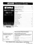
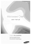
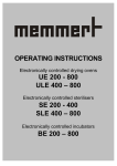
OPERATING INSTRUCTIONS
UM 200 - 800
SM 200 - 400
ULM/SLM 400 - 800
06/99
TABLE OF CONTENTS
1
Congratulations on your choice of a MEMMERT Oven!
2
2
Technical data summary
3
2.1 Electrical supply
3
2.2 Installation options (special equipment)
5
2.3 Wall mounting (special equipment)
5
2.4 Stacking device (special equipment)
5
3
Putting into operation
6
4
Main switch module with fresh air control
7
5
Working controller module
8
6
Operation with timer (special equipment with UM/ULM ovens)
8
7
Safety devices
9
7.1 Adjustable overheat controller (TWW), class 3.1 according to DIN 12880
9
7.2 Adjustable temperature limiter (TWB), class 2 according to DIN 12880
10
8
11
Directives for sterilisation in MEMMERT- hot-air sterilisers
8.1 Notes on the work with sterilising cassettes:
12
9
Loading
13
10
Maintenance
13
10.1 Readjusting the door
14
11
Cleaning
15
12
Our Address
15
Declaration of Conformity UM/ULM
16
Declaration of Conformity SM/SLM
17
Index
18
13
UM 200-800/SM 200-400, ULM/SLM 400-800
The text of these Operating Instructions has been translated from the German. If
any part of the text is doubtful or the interpretation is unclear, and also in case of
errors, the German original is to be considered as valid.
1
Congratulations on your choice of a MEMMERT Oven!
Manufactured in Germany using the latest production techniques and finest materials
available, you now possess a technically superior and fully developed product. Your oven
has already been under extensive testing in our factory.
For correct operation of the equipment it is essential to observe the operating and
maintenance instructions below. This will ensure that your equipment will give many years'
satisfactory service.
Explanation of symbols:
These symbols mark important indications in the operating instructions
The corresponding markings on the oven mean:
Note the Operating Instructions!
Attention, outside case temperature may be hot!
General safety instructions.
The physical and chemical properties of your load (e.g. inflammation
temp, etc.) have strictly to be observed, as otherwise considerable
damages (load, oven, surroundings of apparatus) can appear.
Please note that the Memmert ovens described here are not
explosion-proof (they do not conform to Occupational Association
Regulation VBG 24). They are therefore unsuitable for drying,
evaporating or burning-in of enamels or similar substances whose
solvent may form an inflammable mixture together with air. There
must be no possibility for inflammable or explosive gas/air mixtures
to form either inside the oven or in the immediate neighbourhood of
the equipment.
Excessive dust or aggressive vapors in the interior of the oven may
result in sediments within the oven and cause short circuits or
damage to the electronic parts. Therefore dust and aggressive vapors
should be kept from the oven.
Transport:
Always use gloves !
If the ovens have to be carried, at least 2 persons are required for this
mode of transport depending on size (Model 200 to 500) or at least 4
persons (Model 600 and 700)
Attention!
Take special care when working at high temperature!
Outside case temperature may be hot!
UM 200-800/SM 200-400, ULM/SLM 400-800
2
Technical data summary
MEMMERT appliances are electrically heated and thermostatically controlled. Series
UM/SM have natural air circulation whilst series ULM/SLM have fan assisted circulation.
A PT100 DIN B, DIN 43 760 measures the temperature in the working chamber.
Ambient
conditions
Ambient temperature 5°C - 40°C, rH max. 80%.
Overvoltage Category: I I
Contamination degree: 2 according to IEC 664
Setting temperature range
30°C to nominal temperature
(See rating plate)
Min. working
temperature
range
A stable temperature control of ovens without fan resp. with fan
switched-off can be guaranteed from 5°C above ambient temperature.
Due to the heat generated by the fan motor, a stable temperature control
of ovens with fan can only be guaranteed from approx. 10°C above
ambient temperature.
Max. working
Nominal temperature = maximum temperature (see rating plate),
temperature range
Overheat safety
device
Class
2
3.1
2.1
Serial adjustable overheat control in compliance with DIN 12880 Class
3.1; Class 2 protection (adjustable temperature limiter) available on
request.
Aim of
protection
Scope of
protection
No risk liable to
originate from the
oven in the event
of a fault
Protection of
the oven, the
environment
and the
The contents of
contents of the the oven are
protected against
oven
overheating
Safety
Safety
device
measures
TWB
(adjustable temperaure limiter)
automatically shuts off the
Special safety
oven if the user selected
measures required
temperature limit is exceeded. depending on the
purpose for which
TWW
(adjustable overheat controller) the oven is used
takes over control of oven if
temperature is exceeded.
Electrical supply
50 or 60 Hz. Adequate insulated supply which incorporates earth conductor according to
EN 61010, Protection IP 20, no humidity protection according to DIN 40 050. Interference
suppression Grade N according to VDE 0875, limiting values of the class B, part one.
A fuse 250V/15A quick is used for oven protection (in ovens with 400V 3N~ power supply
3 fuses).
Before current-connection please compare label on the oven and instructions of
your local current supplier.
(e.g. in Germany, DIN VDE 0100 with Fl - safety device).
UM 200-800/SM 200-400, ULM/SLM 400-800
volume
current consum.
UM/SM 200
model
32 1
4,78 A
UM/SM 300
39 1
5,22 A
6,09A
8,70 A
10,43 A
5,80 A
6,96 A
UM/SM/ULM/SLM 400
531
UM/ULM/SLM 500
108 1
UM/ULM/SLM 600
256 1
UM/ULM/SLM 700
416 1
UM/ULM/SLM 800
749 1
power
1100W
1200W
1400W
2000 W
2400 W
4000 W
4800 W
voltage ±10%
230 V~
230V230 V~
230 V~
230 V~
400 V 3N~
400 V 3N~
weight
28 kg
30 kg
35 kg
50 kg
87 kg
121 kg
164 kg
Quality of material
Memmert is using stainless steel (Spec. 1.4301) for the external casing as well as
for the interior, an outstanding material because of its high stability, optimum
hygienic features and corrosion resistance against many (not all!) chemical
combinations (Attention e.g. at chlorine combinations!).
WARNING!
Before removing top cover - pull out plug !
UM 200-800/SM 200-400, ULM/SLM 400-800
2.2 Installation options (special equipment)
The oven can be set up on the floor or on a table (bench),
model 500 - 700 on a subframe. Ensure at least 150 mm
clearance between back of oven and wall. The distance
between ceiling and oven should not be less than 200 mm
and the minimum wall spacing to the sides is 80 mm.
Generally, a sufficient circulation of air around the oven is
required.
After the oven has been set up horizontally the door can be
adjusted if required (see chapter - MAINTENANCE).
The model 800 is movable. The front castors are lockable by means of a fixation. In order
to assure stability, the front castors must always be adjusted to the front side of the
oven for locking.
2.3 Wall mounting (special equipment)
Up to model 700 for all ovens metal mounting brackets are
available. A mounting bracket is delivered with an
incombustible plate. The dimensions of the fixing screws
are to be choosen depending on the total weight
(equipment and loading) of the charge and the quality of the
wall.
model 600
Pitches of holes for wall fixation (wall bracket)
A
model
B
mm
200
300
400
500
600
700
inch mm
inch
489 19,25 770 30,32
569 22,4 770 30.32
489 19,25 850 33.47
649 25,55 930 36,61
889 35,00 1090 42,91
1129 44,45 1250 49,21
C
mm
inch
540
410
21,26
16,14
2.4 Stacking device (special equipment)
Where the requirement is for two ovens of the same size to
be placed one on top of the other, the oven with the lower
working temperature should be placed on the bottom .
Mounting:
o Remove the top of the bottom oven and turning it upside
down place the drilling jig into the back corner. Mark out
the hole position and drill a 4,2 mm diameter hole.
o With the screws provided fix the centering cylinders into position. Re-fix top cover,
o Model 700 can only be stacked with an intermediate frame.
UM 200-800/SM 200-400, ULM/SLM 400-800
3
Putting into operation
Attention !
Extremely strong shocks during transport can cause a displacement of
the temperature sensors in the holding clips inside the working space.
Take care before the first putting into operation that the temperature
sensors are checked on their correct position and if necessary are
slided cautiously backwards or forwards in the holding clip (see fig.).
Ceiling of working
space
temperature sensor
digital display
temperature sensor TWW/TWB
back panel of working space
Handling of the door
The door is opened by pulling the door knob, and is closed by pushing in the door knob.
Attention!
When the oven is started up for the first time it should be run under
supervision until steady conditions are reached.
UM 200-800/SM 200-400, ULM/SLM 400-800
4
Main switch module with fresh air control
The main switch module contains:
o main switch to select the working mode
o three signal
lamps
g
p for display
py of the oven status
o slide knob for fresh air control
o Main switch in position 0:
oven is shut down
o Main switch in position I:
continuous operation
o Main switch in position © :
Operation with timer (special equipment)
Green:
wed:
ready for operation fault indicator
fresh air
Tr:
—3
""5
"6
Yellow:
oven is heating
Flap closed: virtually no through ventilation.
Intermediate positions: the air in the camber is renewed to a
limited extent.
Maximum fresh air ventilation, but no complete change of air
within the chamber (in ovens with an air turbine by max.
rotation speed).
UM 200-800/SM 200-400, ULM/SLM 400-800
*I
5
Working controller module
The controller is operated with the aid of the rotary
knob.
o
Set temperature regulator rotary knob to desired
temperature
o
Scale can be locked by turning screw lock.
When the working temperature is reached, intermittent illumination of the yellow pilot lamp
indicates operation of the thermostat. If there are big differences between set-temperature
and digital display, this can be eliminated by adjusting the controller (see maintenance).
Severe transport and extreme climatic conditions may cause discrepancies (ambient testtemperature about 22QC).
6
Operation with timer (special equipment with UM/ULM oven)
Main switch in position 0
A
I
0
©
Mi
P mf
© •
IS
14
o
Set temperature regulator rotary knob to desired
temperature (see chapter Working controller
module).
o
Set the required time period.
Running time 50 Hz = 24 hours
Running time 60 Hz = 20 hours.
Oven is automatically turned off when the elapsed time has run down.
Timers are available for fitting by the user after delivery and full instructions are
supplied with the timers to be retrofitted.
The installation has to be made by a service engineer.
UM 200-800/SM 200-400, ULM/SLM 400-800
7
Safety devices
The oven can be equipped with an adjustable overheat controller (TWW), class 3.1 or
adjustable temperature limiter (TWB), class 2. Both work independently of the
temperature control system according to DIN 12880. By different adjustments, those
safety devices can have two different functions:
o Protection of oven and environment and additionally
o Protection of the load from excessive temperature
The safety devices should be checked at regular intervals, e.g. once a month, once the
oven has stabilised at the desired temperature. To perform this safety check, reduce the
setting of the safety device until the red control light at the main switch module turns on.
After that, the safety device can be set again.
^
i
Notice:
safety temperature
150°C
During operation the safety device has to be set
sufficiently higher than the maximum working
temperature or at the maximum temperature of
the oven.
working
temperature
(
t
7.1 Adjustable overheat controller (TWW), class 3.1 according to DIN 12880
Protection of oven and environment:
o Turn the adjustable overheat controller e.g. by
use of a coin to upper temperature limit.
Protection of load:
o First turn adjustable overheat controller to upper
limit,
o After the oven has stabilised, the setting of the
overheat controller should be moved down until
it operates.
Upper
temperature
limit:
Protection of
oven and
environment
Set close to
the switching
point:
Protection of
the load
o The red signal lamp in the main
switch module turns on.
I 0 ©
o Now turn back the overheat controller to nearly
one digit higher.
UM 200-800/SM 200-400, ULM/SLM 400-800
Maximum temperature rating of oven
220°C
one scale line means approx.
15°C
Should the temperature rise above the set safety temperature, the adjustable overheat controller takes over the temperature control.
o the ,,alarm" lamp turns on
as soon as the TWW has switched off the heating
In this case please check the TWW setting as described and readjust it if
necessary. Should a fault condition be present, please contact an authorised
service station for Memmert equipment.
7.2 Adjustable temperature limiter (TWB), class 2 according to DIN 12880
Protection of oven and environment:
o Turn temperature limiter e.g. with a coin to upper
temperature limit.
Protection of load:
o First turn temperature limiter to upper temperature
limit.
o After the oven has stabilised, the temperature
limiter should be moved down until it operates.
Upper
temperature
limit:
Protection of
oven and
environment
Set close to
the switching
point:
Protection of
the load
o The red signal lamp in the main
switch module lights up.
0 ©
o Now turn back the temperature limiter to nearly
one digit higher.
o The temperature limiter must be
reset by pressing the
knob.
Maximum temperature rating of oven
220°C
one scale line means approx.
15°C
Should the temperature rise above the set safety temperature, the adjustable
temperature limiter switches off the heating.
o
the ,,alarm" lamp turns on.
In this case please check the TWB setting as described and readjust it if
necessary. Should a fault condition be present, please contact an authorised
service station for Memmert equipment.
10
UM 200-800/SM 200-400, ULM/SLM 400-800
8
Directives for sterilisation in MEMMERT- hot-air sterilisers.
For the hot air sterilisation, many directions exist concerning the temperatures and
sterilisation times to be selected as well as the packaging of the sterilisation goods. The
data to be selected, depend on the nature of the goods to be sterilised and on the type of
the germs to be deactivated. Please make yourself familiar with the applicable direction
for your application before carrying out a sterilisation with your MEMMERT steriliser.
Some examples for the correct preparation of different medical instruments are shown in
the following table:
Preparation
Place the cleaned instruments, twin-packed in aluminium
foil (recommendable)
Place flasks and cylinders separately, twin-packed in
aluminium foil (recommendable)
Disassemble the cleaned glass containers and glass
Glass and glass instruments
syringes. Place on trays - cool slowly
Bottles and similar items must be sterilised with the opening pointing downward in order to
prevent the development of cold air nests. Organic fabrics (e.g. cork) must not be used as
closing material for bins.
180°C are usually recommended as sterilising temperature (cf. German drug book DAB 10
or other national standards).
The whole required time period is setted using the timer. The time period consists of the
heating time, the equalising time (i.e. the time it takes until the desired temperature is
reached at any point of the working chamber), of the actual sterilising time and the safety
surcharge.
Charging
Instruments with no soft soldered parts / sharp Instruments
Modern Syringes (no plastic)
The following table shows rough values for the hold time to be selected at the controller, in
dependence of the weight of the sterilising load for ovens with and without air turbine (fan).
Please note, that this data can only be applied for correct, loose loading. Information on
the right loading of the oven are given in this operation manual and on the adhesive label
directly on the steriliser.
Sterilisation temperature = 180°C
Weight of the load
mec ium
low
SM/SLM
without fan
heating +
sterilising time
with fan
heating +
sterilising time
200
3/4+3/4=11/2h
-
300
^ + 3 ^ = 11/2 h
-
400
%+1 1 /4=2h
i
1
1
without fan
heating +
sterilising time
with fan
heating +
sterilising time
3
/4 + 11/4=2h
3/4 + 13/4=2 1/zh
-
-
3/4+134=21/2 h
-
/4+11 /4=2h
1+2=3h
3/4+13/4=21/2 h
/4+1 %=2 h
1
3
/4 + 13/4=21/2 h
with fan
heating +
sterilising time
-
3
/2+i=iy2h
hi 3h
without fan
heating +
sterilising time
3
500
3/4 + 1 /4=2 h
/4+1 /4=2 /2 h
34+11/4=2 h
1+2=3h
3/4+134=21/2 h
600
1+1 1 /2=2 1 /2h
1+1=2h
1+2 1 / 2 =3 1 / 2 h
1+11/2=21/2h
11/4+21/4=31/2 h
1+2=3h
700
1+1 1 /2=2 1 /2h
1+1=2h
1+2 1 /2=3 1 /2h
1+11/2=21/2h
1i/4+2i/4=3i/2h 11/4+214=31/2 h
800
1 1 / 2 +1 1 /2=3h
11/4+11/4=21/2h
1 1 /2+2 1 / 2 =4h
1 !4+134=3 h
1
1
11/2+21/2=4 h 1i/4+2 /4=3 / 2 h
/2+1=1 /2h
3
3
1
The sterilisation time has to be multiplied by about 4, if a sterilisation temperature of 160°C
is selected.
UM 200-800/SM 200-400, ULM/SLM 400-800
11
With large ovens and heavy loads, the use of grates (option) is recommended instead of
the perforated shelfs.
In particular with heavy loads, the untested usage of these provisional values is not
sufficient. For a safe sterilisation, a validation of the individual sterilisation process must be
done, using e.g. additional temperature sensors or germ packets.
When sterilising the air flap has to be closed after the humid load has been dried.
Note: In case of a power failure the sterilising process may not be completed
properly. Therefore a permanent observation of the sterilising process or of
the mains supply is necessary to provide a safe sterilisation.
8.1 Notes on the work with sterilising cassettes:
The cassettes should be placed in the steriliser so that the hot air can flow easily through
the air ducts (in an steriliser with air turbine the airstream flows crosswise through the
working space). The directives about correct loading, which can be found in this operating
manual and on the steriliser have to be followed also when using sterilising cassettes. This
makes sure that a good temperature distribution is obtained and that the development of
cold air nests is prevented.
The sterilisation load must be packed in aluminium foil as shown in the table and must be
placed in the sterilising cassettes. The air ducts of the box must be opened for sterilising.
A temperature sensor for the verification of the temperature can be brought into the
sterilising cassette through opening 2.
After the sterilising time has elapsed, the air ducts must be closed by shifting knob 1 in
the direction of the arrow.
In this way, the sterilised goods can be preserved in the closed cassette for some days.
12
UM 200-800/SM 200-400, ULM/SLM 400-800
9
Loading
Ovens described in this instruction manual must not be used for
drying or warming substances which generate ignitable vapours
when mixed with air.
The ovens described here must never be operated in areas with an
explosive atmosphere.
For correct operation and uniform temperature distribution it is essential to maintain free
air circulation throughout the oven. The contents of the oven should therefore not be
packed tightly, furthermore they must not be placed close to any of the heating ribs on the
sides, top or bottom of the oven (note the loading diagrams on the ovens).
In order to ensure optimum air circulation the shelves should be arranged to have roughly
equal gaps between door, shelf and the rear of the working chamber.
For the maximum number of shelves with the permissible load, see table below.
In certain situations where, for example, the load is packed tightly and the ventilation slide
is fully open it is possible that the unit will control at a temperature below that set on the
thermostat. In order to compensate it may be necessary to increase the thermostat setting
until the desired temperature is shown on the digital display of the working controller.
The following schedule gives recommended loading levels which will ensure
homogeneous temperature distribution within the working chamber.
Model
200
300
400
500
600
700
800
Max. number of
shelves
3
3
4
5
7
8
10
Load each shelf
max. kg
15
12
15
15
30
30
30
Total load
kg
30
30
40
50
80
100
160
10 Maintenance
General information
Memmert appliances require minimal servicing. It is recommended, however, to lubricate
the mechanical parts of the doorhinges and movable parts of the door lock from time to
time. Under normal conditions this should be done annually but up to four times a year if
undergoing continuous operation. Use a heat resistant oil or thin silicon grease. The
movable parts of the temperature controller should be lubricated too. Therefore use
silicon grease.
In case of a fault which makes necessary to open the oven it has to be checked by
a qualified service engineer.
Adjustment
It is necessary to keep the top of the oven closed in case of readjustment.
Empty oven with one empty shelve in the middle has to be heated up to maximum
temperature and allowed sufficient time to reach steady temperature condition. (Please
wait at least 60 min.).
UM 200-800/SM 200-400, ULM/SLM 400-800
13
1. Remove a screw on the cover at the lower part of the back wall and swing up the cover
as until the opening in the back wall is clear.
2. Turn the adjusting disk (knurled disk, approx. 60 mm behind the back wall) with a tool
(e.g. screwdriver) through a small angle. (Danger! The disk is hot!)
Turning to the left increases the control temperature.
Turning to the right decreases the control temperature.
Look at the marks above cover plate at the back
side.
cover plate
Adjusting disk
normal regulator
3. Make only small adjustments at any one time and pause (approx. 45 min) so that the
effect of the adjustment can be noted on the digital display before further adjustments
are made.
4. If required repeat the recalibration. It is essential to close the cover again and
secure it in position after each action.
Note
After each adjustment it is essential to close the cover and secure it in position.
A tightly closing door is an essential requirement on ovens. MEMMERT-ovens ensure
perfectly tight closing of the door through a seal on the oven casing. The door seal
presses accurately against the casing seal. In continuous operation the flexible seal
material may acquire a permanent set. For proper closing of the door it may be necessary
to adjust the hinge or the locking plate.
10.1 Readjusting the door
After releasing the screw No. 12 (ATTENTION!
Screw No. 12 is secured with glue. Loosen jerky
with inner hexagon key wrench 2 mm) the door
can be adjusted by turning the eccentric 13 in the
direction of the arrow (using a screwdriver).
Tighten screw No. 12 again.
In addition the upper part No. 14 of the door hinge
can be moved slightly in the direction of the arrow
after releasing the 2 screws at the top or bottom of
the door.
„,
'•
•
14
12
The locking plate can also be readjusted in the
direction of the arrow after releasing the screw
No.15.
Ensure that the cover is again screwed down
tightly.
14
UM 200-800/SM 200-400, ULM/SLM 400-800
11 Cleaning
By regular cleaning of the easy to clean interior, residues are avoided
which at continuous influence can impair the outfit and function of
the oven.
The oven can be cleaned with commercial stainless steel cleaning agents. Please note
that objects liable to rust must not be placed into the interior. Rust sediments lead to
contamination of the interior or external casing.
If rust stains caused by contamination occur on the interior surface, the affected areas
must be cleaned and polished immediately.
The details in these Operation Instructions must be carefully observed in order to ensure
satisfactory operation.
Warranty and claims for damage are excluded if these instructions are disregarded.
We reserve the right to make changes in technical specifications.
Dimensions subject to confirmation.
Standard ovens are safety-approved and bear the test marks:
E l W l V
12 Our Address
ME52
MEMMERT GmbH+Co.KG
P.O.Box 17 20, 91107 Schwabach
Federal Republic of Germany
« . 09122/925-0*
Fax 09122/14585
Internet www.memmert.com
Direct dialling-in service department
« . 09122/925-127/128
E-Mail heinz.baver@ memmert.com
© by MEMMERT GmbH+Co.KG
from 9/98
D 07967
UM 200-800/SM 200-400, ULM/SLM 400-800
15
DECLARATION OF CONFORMITY
Document-No.
Manufacturer:
D 06851
Address:
AuGere Rittersbacher StraGe 38
91126 Schwabach
Product name:
Universal Oven
Type:
MEMMERT GmbH + Co.KG
UM/ULM/UE/ULE/UP/U
Sizes: 100 / 200 / 300 / 400 / 500 / 600 / 700 / 800
Nominal voltage: AC 230 V or 3N AC 400 V 50/60 Hz
from 11/95
The above mentioned product has been manufactured according to the regulations of the
following European directives proven through complete compliance with the following
standards:
No.
73/23/EWG
73/23/EEC
Directive
Electrical equipment for use within certain voltage limits
Low Voltage Directive - Attachment of CE mark: 95
Standard
DIN VDE 0411 part 1/03.94 (EN 61 010-1 : 1993, IEC 1010-1 : 1990 + A1 : 1992)
DIN VDE 0411 part 2-010/03.95 (EN 61 010-2-010 : 1994, ICE 1010-2-010 : 1992)
No.
Directive
89/336/EWE
89/336/EEC
Electromagnetic compatibility
- EMV - directive
Standard
VDE 0839 part 82-1 : 1993-03 (EN 50082-1 : 1992)
VDE 0875 part 14
: 1993-12 (EN 55011 : 1991)
DIN VDE 0875 part 1 : 1992-07 (EN 55014 :1993)
Place, Date
Signature :
Schwabach, 16.09.98
Management
This declaration certifies compliance with the above mentioned directives but does not include a
property assurance. The safety note given in the product documentation's, with are part of the
supply, must be observed.
16
UM 200-800/SM 200-400, ULM/SLM 400-800
DECLARATION OF CONFORMITY
Document-No.:
D 06879
Manufacturer:
MEMMERT GmbH + Co.KG
Address
AuGere Rittersbacher StraBe 38
91126Schwabach
Product name:
Steriliser
Type:
SM/SLM/SE/SLE/SLP
Sizes: 100 /200 / 300 / 400 / 500 / 600 / 700 / 800
Nominal voltage: AC 230 V or 3N AC 400 V, 50/60 Hz
From 11/95
The above mentioned product has been manufactured according to the regulations of the
following European directives proven through complete compliance with the following
standards:
No.
73/23/EWG
73/23/EEC
Directive
Electrical equipment for use within certain voltage limits Low Voltage Directive - Attachment of CE mark: 95
Standard
DIN VDE 0411 part 1/03.94 (EN 61 010-1 : 1993, IEC 1010-1 : 1990 + A1 : 1992)
DIN VDE 0411 part 2-010/03.95 (EN 61 010-2-010 : 1994, IEC 1010-2-010 : 1992)
No.
Directive
89/336/EWG
89/336/EEC
Electromagnetic compatibility
- EMV - directive
Standard
VDE 0839 part 82-1 : 1993-03 (EN 50082-1 : 1992)
VDE 0875 part 14
: 1993-12 (EN 55011 : 1991)
DIN VDE 0875 part 1 : 1992-07 (EN 55014 : 1993)
Place, date : Schwabach, 30.04.98
Signature :
Management
This declaration certifies compliance with the above mentioned directives but does not include a
property assurance. The safety note given in the product documentation's, with are part of the
supply, must be observed.
UM 200-800/SM 200-400, ULM/SLM 400-800
17
13 Index
A
adjustable temperature limiter
adjustment
alarm
O
3, 9, 10
13, 14
10
overheat safety device
P
Pitches of holes for wall fixation
5
power
3, 4, 12
putting into operation
6
C
cleaning
current-connection
15
3
Q
D
digital display
door hinge
quality of material
8, 14
readjusting the door
S
safety device
shocks during transport
stacking device
sterilisation
sterilising cassettes
T
temperature regulator
temperature setting
timer (special equipment)
transport
3
F
fresh air
7
fresh air ventilation
7
H
handling of the door
6
/
installation options
5
locking plate
14
9
6
5
11
12
8
8
7
8
W
L
loading
4
R
14
E
Electrical supply
8
wall mounting
working controller module
working temperature
5, 11, 12, 13
14
5
8
5, 8, 9
M
main supply switch
main switch module
maintenance
8
7
2, 8, 13
18
UM 200-800/SM 200-400, ULM/SLM 400-800
D 07967
UM 200-800/SM 200-400,
ULM/SLM 400-800