1
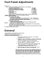
Athena 6000/6200
Microprocessor-based Temperature Controller
Designed for the user
software linearized and stabilized
thermocouple input with 3-mode PID
action heat/cooling control and dual
alarms, ºF to ºC conversion, alarms
that can be energized for temp
rise/fall and selectable as process
or deviation type, and a program
restart circuit that eliminates
program lock-up due to transient
voltage spikes or line voltage
“brown out.” Program automatically
restarts within 2 milliseconds after
condition passes.
Athena’s unique new 6000
microprocessor-based controller
was developed to satisfy the needs
of actual end users, designers, and
specifiers. Data was gathered on
the temperature controller features,
functions, and performance capabilities that they desired. Then
Athena designed a controller to
satisfy them.
Dual lndication
Now you can compare process
temperature and setpoint at a
glance - hands free. This dual
digital display concept has formerly
only been available in high priced
multifunction process controls.
PID Control
Microprocessors reduce size,
add extras
Three mode (Proportional,
lntegral, and Derivative) action
eliminates offset (droop) as cooling
and heating requirements change in
the process, and provides fast
output response to rate of change
and reduces temperature overshoot
and undershoot.
By using microprocessor
hardware and a highly sophisticated
software package, Athena designers
and engineers have included more
features than have ever been
available before in a controller this
size. Incorporating two digital
displays, touch-key operation,
Thermocouple linearization
The 6000 has a program to
linearize signal input from the
thermocouple. Without it, temperature controllers have accurate
temperature indication over only
certain portions of the scale.
Contents
PAGE
General: Introduction
Configuration:
Output Forms
Alarm Types
ºC/°F
Installation lnstructlons:
Unpacking
Locating
Mounting
Terminal Designations
Output Modules
Wiring Examples
Internal Switches
Thermocouple lnstallation
PAGE
2
Operating Instructions:
Control Panel Description
Start-up
Parameter Entry
Heat Galn Setting
Rate Setting
Examples
Cool Gain Setting
4-5
4-5
4-5
5
5
5
6
6-7
6-9
10
11
2
13
13
13-14
15
15
15
15
Trouble Shootlng
16
Repairs and Warranty
16
Specifications
Inputs:
Line Voltage
Sensor
Power consumption:
Ranges available:
Accuracy:
Temperature stability:
Cold end tracking:
Operating ambient for
rated accuracy:
Maximum lead
resistance for rated
accuracy:
Series mode noise
rejection:
Common mode noise
rejection:
T/C break protection:
Dual display:
Display update rate
and filtering
ºF/ºC:
Alarm 1 & 2:
Outputs:
- B Relay (time
proportioning)
-F Current
proportional
-S Pulsed voltage
-T Triac (time
proportional
-E1 & E2 Auxiliary
alarm relays
(on/off)
Filtered LED display:
T/C linearization:
Connections:
Dimensions:
Mounting:
Weight:
Recorder output:
(RTD only)
+10
120/240 Vac -15% 50,60 Hz
T, J or K thermocouple or Platinum 100Ω at 0°C
Less than 6 VA (Instrument)
J couple 0-1400°F (0-760%)
K couple 0-2000°F (0-1093ºC)
±1 digit of full scale
5 µV/ºC Max 3 µV/ºC typ.
0.05ºC/°C ambient
0 to 55%
Thermocouple: 100Ω
RTD: 10Ω/lead
60 dB
120 dB
upscale standard
Process temp displayed continuously; setpoint or other
parameters updated on lower display
Greater than 5 times per second.
Analog and digital filtering techniques increase stability of
process & display.
Internal switch selection-process, setpoint and alarms
affected.
Adjustable over full range of control. LED displays alarm
status. 3 amp relay at 120 Vac normally open contact.
Reverse acting relay by switch selecting or low alarms.
Process/deviation mode selectable (internal switch).
Available heating only or heat/cool
SPST relay 7 amps resistive at 120 Vac, 5 amp resistive
at 240 Vac, 50 VA inductive
4-20 mAdc into 500 ohm max.
0-20 Vdc pulsed time proportioning signal for driving solid
state relays 500 ohms maximum input impedance
Solid state plug-in triac output. Rated 1 amp holding &
10 amps inrush
SPST relays, rated 3 amps at 120 Vac
4 digits for process, 4 digits for parameters.
Continuously calculated and updated using rom based
algorithm.
Inputs and outputs vla barrier strips with U.L. approved
Iocking sems terminals.
Front panel: 96mm x 96mm x 22mm
Case: 92mm x 92mm x 118mm
Depth behind panel: 96mm (approx. minus panel thickness)
Channel slides and screws
2 lb
1 mV/ºC for degree reading unit
0.1 mV/ºC for 1 10 degree reading unit
3
Front Panel Adjustments
Touch Key
Index: Allows the following adjustments to be selected.
1) set point temperature
0 to span
2) alarm one temperature setting
0 to span
3) alarm two temperature setting
0 to span
4) rate with tracking reset (1:6ratio)
** 0 to 120 sec
5) heat gain
*** 1 to 400
6) heat cycle time
* 1 to 120 sec
7) cool gain
*** 1 to 400 x
6) cool cycle time
* 1 to 120 sec
up/down keys: increases/decreases values of above adjustments
Enter: writes selected values to nonvolatile memory
Internal switches/jumpers
A) 4 position dip switch
1) selects ºF/°C display
2) selects energized alarm two on hi/low (dev + / dev -) temperature
3) selects energized alarm one on hi/low (dev + / dev -) temperature
4) selects process or deviation alarm function
B) 2 position dip switch
1) selects reduced rate gain
2) locks out front panel parameter entry excepting set point
NOTES: *** setting to zero disables output
* setting to zero initiates 60 millisecond timebase for ultra fast cycling.
Use with external solid state relays.
**Setting to zero disables reset and rate actlon for proportional only control.
To order see price sheet C-5-82
General
Congratulations on purchasing an outstanding
temperature controller Ingenious use of
microprocessor technology has given you an
economical, compact controller that:
1. Accurately measures, linearizes and displays
temperature in º F and º C .
2. Digitally enters and displays control and alarm set
points as well as heat and cool gains, cycle times,
and user simplified rate and reset action.
3. Can be switched configured for high and low
process alarms or deviation alarms.
4. Can be field converted from relay output “B”, to
solid state relay "T" to solid state relay driver "S"
or to a 4-20 MA output SCR driver "F", with
independent outputs for heat and cool.
5. Will remember its “entered” settings after power
failure or shut-off and not “Go To Sleep”.
CAUTION: HIGH VOLTAGE AND HIGH TEMPERATURES CAN
CAUSE INJURY AND ARE A FIRE HAZARD. PLEASE READ
ALL INSTRUCTIONS, HAVE ONLY SKILLED PROFESSIONALS
WIRE THE UNIT, AND USE AN APPROVED TEMPERATURE
AND/OR PRESSURE SAFETY CONTROL. EVEN THE BEST
COMPONENTS CAN BE DAMAGED OR MAY NOT FAIL SAFE.
4
Output Modules
times less than ten seconds will drastically shorten
relay life and in no case should the cycle time be set to
zero (60 millisecond time base). Normally open
contacts are provided for both heating or cooling use.
NOTE: Do not use this output module with mechanical
contactors because they generate an excessive EMI
field which can lnterfere with other controllers. Instead
we recommend "T" output modules for this applicatlon.
Module Type F:
Module Type T:
Module Type S:
This 4-20 mA output module can deliver full output to
loads having an input Impedance of 500 OHMS or less.
The cycle time setting must be ZERO for smooth
current output.
A push-on terminal is utilized as a return for ground
currents of the milliamp source. It is connected
Internally to the mating lug on the heatsink. To avoid
ground loops, drive floating (ungrounded) loads or use
isolated thermocouples.
This solid state relay is capable of 1 AMP at
120/240Vac. It is zero voltage switched and optically
isolated from the drive signal. With it, resistive loads
up to 120 watts at 120Vac and 240 watts at 240Vac
may be controlled directly. Using direct control there
is no lower limit on the cycle time setting (down to
60 milliseconds).
Larger loads may be controlled utilizing an external
contactor. In this case, It is advisable to use cycle
settings of ten seconds or greater to minimize
contactor wear. External suppresslon of the contactor
is advisable if EMI becomes a problem.
Similar to F, but pulsed 20V/20mA DC output for
driving solid state relays. Up to 6 (series input
connected) solid state relays can be used. Cycling
time (HC) can be set to optimize the load response
time requirements without sacrificing relay life.
7
Installation Instructions
variable, the probe should be close to the work area.
Some experimenting with probe location is often
needed to find its optimum position.
In a bath process, the addition of a stirrer will help
to eliminate thermal lags. Since the thermocouple is
basically a point measuring device, putting more than
one thermocouple in parallel will provide an average
temperature reading and produce better results In air
heated processes.
NOTE: if controls with “F” or "S” outputs drive loads
with grounded or hot input terminals (not floating), an
isolated thermocouple must be used. Otherwise, when
both input and output are grounded, severe ground loop
currents will result, causing errors and permanent
controller damage.
Standard thermocouple limits of error are ± 4ºF or
0.75% (half that for special) plus drift caused by
improper protection or over temperature. This is far
greater than controller error, but can not be corrected
at the sensor except by selection and replacement. In
extreme case, total system requirements can be met by
offsetting the control to compensate for these outside
errors.
Operating Instructions
Control Panel Description
LED To indicate
Output “Status"
Continuous
Display Of
Process
Variable
Continuous
Display Of
Setpoint Or
Indexed
Parameter
Function Selected
Indicated By LED
“Cursor”
Advanced By “I”
Button
Touch Key Group
Pressing The “I”
Button Advances
The Cursor In The
“Index” Group
Enters The
Selected Value TO
Nonvolatile
Memory
Raises (lncreases)
The Selected
Variable
Lowers
(Decreases) The
Selected Variable
12
Operating Instructions
Start-Up
Before line voltage is applied, double check all items
connected to controller: The correct type thermocouple
(see section on thermocouples, p. 11) must be on
terminals 1 and 2 (red on 2) with no AC or DC voltage
leading or arcing to it. Proper terminals selected for
line voltage (8 & 10 for 240V). No heater shorts or
shorts to ground. No exposed bare wires or frayed
insulation.
On very fast processes heaters should be temporarily
disconnected to give operators familiarization time
without exceeding safe temperature limits of the
process.
Set point: Apply power. After allowing a few seconds
for initialization, the upper display will indicate
thermocouple temperature at the process, the lower
display wil show set point temperature, and the index
indicator illuminates set point (SP). The status (output)
indicator will pulse with a greater “on” time as the
difference between actual process temperature and set
point widens, and at lesser “on” time as the difference
narrows.
To establish a setpoint, first make sure the index
light is still on (SP). Then depress the UP button to
increase the value shown in the lower display, or the
DOWN button to decrease it, until the desired setpoint
is reached. To retain this parameter in the non-volatile
memory, depress the “enter” key E. Display will blink.
Alarms: Depress index key (I) until index indicator
lights at (Al). Now set alarm one trip point by up or
down keys as before. Enter (E). If configured as
deviation tracking alarm, the lower display shows
difference between set point and the point where alarm
is triggered. (See p. 10 to select alarm functions).
Depress index key (I) again and advance to alarm 2
(A2). Set as above.
Rate: Advance index to rate (RT). This is the rate
(differential or anticipating) action adjustment,
calibrated in seconds. It is software connected to
automatic reset (integral or droop correcting) action,
which automatically tracks rate.
This wide range, high resolution, single button entry
greatly simplifies tuning the control to the process.
Temporarily run it down to zero (proportional only) and
enter (E).
Heat Gain: Heat gain (HG), the next index position,
sets controller gain for heat control. It is the inverse of
proportional band (P.B.) which can be calculated as
ºP. B. = Full Scale º/Gain. At HG = 0, heat is off.
Temporarily set HG = 400 or about 3.5º prop. band on
“J” couple units, 5º on “K”. Proceed to set the next
parameter.
Heat cycling (HC) is next. It should be set to the
longest possible cycling time in seconds (depending on
the mass of process) for increased life expectancy of
relays. 15 to 30 seconds for massive loads, 10 to 15 for
fast loads when relay driven. "T” output solid state
13
Operating Instructions
relays directly connected to small heaters, 0-5 sec., but
not faster than 10 sec. when driving mechanical
contactors. “S” solid state contactor drivers can be
used 0-10 sec. “F” mA output units must be set to
HC = 0, less than 1 sec.
CG Is cooling gain. If no cooling is used, set it to
100, and enter. If cooling is employed, start at CG = 400
and follow procedure to set HG.
The final index position is used to set cooling
cycling (CC) time. On all "T" output units, C = 0. Other
outputs are dictated by the type of cooling method
employed. Mechanical compressors may require
2 minutes, liquid pumps 30 seconds, solenoid valves
5-15 seconds, small fans 5 seconds, large ones 30.
Decide, set and enter (E) to lock in value. Then move
index back to "SP".
Connect power to heater and observe temp. rise. Run
set polnt down to meet process. Heat output will start
proportioning within a few degrees of process
temperature, and cool will proportion once SP is below
process.
Tuning
Heat Gain
Heat Gain
(HG) Setting
An ideal process would glve perfect results with
highest controller gain. Practically speaking however,
heaters are overpowered, have stored heat and poor
coupling, loads have multiple delays, and the sensor
reading lags behind the heating output status. A
controller must be tuneable to process characteristics
in order to compensate for the deficiencies of the rest
of the system. The Model 6000 has been designed so
that it does this and still remains easy to operate.
1. Fix set polnt (SP) at the desired process
temperature. (If overshoot can not be tolerated
durlng set-up, use 20-30% lower temp.)
2. Set heat gain (HG) at 400. Record the range of
temperature oscillations around the set point. Note
their durations.
3. Reduce gain by half (200). Observe and note
osclllatlon (if any).
4. Repeat this halving procedure until temperature
is stable.
5. Push (E) to enter. You have now compensated for
heater power and number of lags, but a droop
between set polnt and process exists.
Rate (RT)
Setting
1. Set rate (RT) to 01 seconds for fast systems, 05 for
slow, 10 seconds for massive.
Observe oscillation building up and record the range.
2.
(includes reset)
3. Double rate time. Observe oscillation.
4. Repeat the doubling procedure until the process
stabilizes again.
5. Then enter (E).
You have now optimized rate and reset times for the frequency response of
the process. If time permits, finer adjustment can be made. For faster start-up
14
Operating Instructions
(with some overshoot) reduce rate time 10-20%. For more anticipation (giving
undershoot) increase rate slightly. Experiment with (HG) settings.
EXAMPLES OF PARAMETER SETTING ON TWO PROCESSES
Process A : Slow, 2 lag process, matched power, 200º set point.
HG
RT
TEMPERATURE
REMARKS
409
00
197º-199º
200
00
196º
200
05
194º-206º
200
200
10
20
199º-201º
200º
200
40
198º-202º
Process shows 2º oscillation, 2º average droop cut gain setting in half.
Process is stable, Gain O.K. but 4º droop-requires
addition of rate-add 05 for slow process.
Process shows 8º slowing oscillation, reset is
hunting, double RT to 10.
Almost -double RT value again.
Good-process is stable. Double again to see if we
can improve.
Now process is showing 4º faster (rate) "hunting”.
Back up again. RT = 20.
Process B: Fast, 3 lag, overpowered process, 400° set point.
TEMPERATURE
REMARKS
HG
RT
409
00
389º-435º
25
00
375º-391
12
00
384º
12
12
12
12
01
02
03
04
371º-435º
396º-404º
400º ±
400º
Process oscillates, wild, skip to much less gain.
With 16º oscillation, 17º droop- galn should be cut
Gain O.K., 36º droop- now add RT = 1 for fast
process.
Need more rate tlme-double to 2.
Getting close-add a little more.
Good-add a little more to see if we can improve.
Optimum
Low gain requirement indicates poor thermal coupling or overpower.
Special problems can be caused by very noisy turbulent flow processes or
by systems havlng a pure dead time between heat application and
temperature measurement. In both cases, rate is likely to continuously
overreact. Unplug unit and set internal switch to reduced rate gain. (From
back of case, your left, B-2, top position).
Cool Gain
(CG) Setting
If cooling is to be controlled, first optimize the heat
adjustments. Start heat generating mechanism
(chemical reaction, mechanical, subambient set point,
etc. that will require cooling action.
1. Set cool gain to 400 (maximum). If stable, enter.
Most likely the temperature will oscillate.
I
Record
values used.
2. Reduce gain to 200. Compare temperature
oscillations. If oscillations are reduced, continue
lowering gain until process is stable.
3. If up and down temperature peaks get bigger, cool
cycling (CC) may be too long or the cooling
mechanism has too much lag or time delay. If
possible, improve dynamics of cool transfer, If not,
go to rate (RT) and double rate time.
4. Now optimize cooling gain as in step 2.
Z:
5. Since heat rate will now be too long, cut heat gain
in half.
15
Trouble
Shooting
Unit Repairs
Front dark - no instrument power, blown fuse or burned
out transformer.
Process display shows CCCC - Open thermocouple.
Short terminals 1 and 2, should indicate temperature at
back of case. Repair or replace thermocouple.
About Half Or Twice Expected Reading- Check
position of ºC or ºF switch. Short 1 and 2 to read room
temperature. 22-30 is %, 70-85 is ºF
About 30% Error - Wrong thermocouple type.
Disconnect couple. “J” units over range above 1400°F,
“K” above 2000°F + .
No Heat - Heater wiring, wrong output module, blown
fuses.
Heat Stays On- Welded relay contacts or shorted
output module. Check for cause and correct the
components.
Process Display Shows 0000 Or Initially Displays Room
Temperature Then Counts Down Scale As Process
Warms - Check for reversed thermocouple.
It is recommended that units requiring service be
returned to an authorized service center. When a
controller is returned for service, a note stating the
problem should accompany the unit. To eliminate
service delay, consult the factory prior to returning any
unit.
A spare parts list can be supplied upon request if
complete model number, serial number and
temperature range is supplied.
Warranty
This equipment is warranted to be free from defects of material
and workmanship. It is sold subject to our mutual agreement that the
liability of Athena Controls, Inc. is to replace and/or repair at its
factory, provided the equipment is returned, transportation prepaid
within (2) years of its purchase.
The purchaser agrees that Athena Controls, Inc. shall assume no
liability for consequential damages resulting from its use or
packaging of shipments returned to the factory.
Components which wear or which are damaged by misuses are not
warranted. These include contact points, fuses and triacs. Units
which have been rewired by customer are not warranteed.
Specifications are subject to change without notice.
Athena Controls Inc., 5145 Campus Drive
Plymouth Meeting, PA 19462
(215) 828-2490