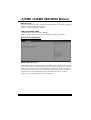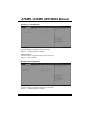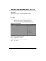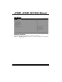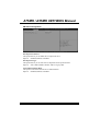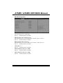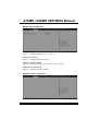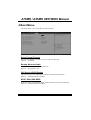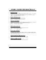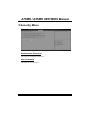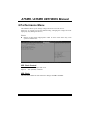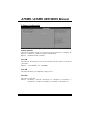
1
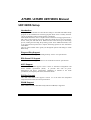
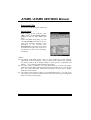
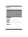
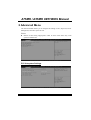
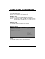
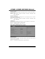
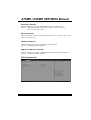
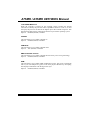
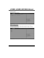
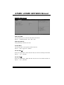
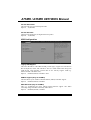
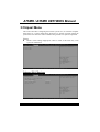
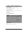
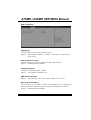
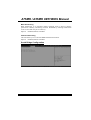
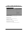
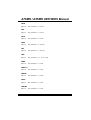
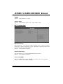
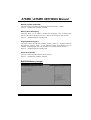
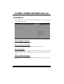
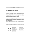
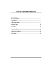
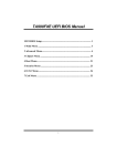
A75MH / A55MH UEFI BIOS Manual
UEFI BIOS Setup...................................................................................... 1
1 Main Menu ............................................................................................. 3
2 Advanced Menu...................................................................................... 4
3 Chipset Menu ....................................................................................... 17
4 Boot Menu............................................................................................. 25
5 Security Menu ...................................................................................... 27
6 Performance Menu .............................................................................. 28
7 Exit Menu ............................................................................................. 36
i
A75MH / A55MH UEFI BIOS Manual
UEFI BIOS Setup
Introduction
The purpose of this manual is to describe the settings in the AMI UEFI BIOS Setup
program on this motherboard. The Setup program allows users to modify the basic
system configuration and save these settings to NVRAM.
UEFI BIOS determines what a computer can do without accessing programs from a
disk. This system controls most of the input and output devices such as keyboard,
mouse, serial ports and disk drives. BIOS activates at the first stage of the booting
process, loading and executing the operating system. Some additional features, such
as virus and password protection or chipset fine-tuning options are also included in
UEFI BIOS.
The rest of this manual will to guide you through the options and settings in UEFI
BIOS Setup.
Plug and Play Support
This AMI UEFI BIOS supports the Plug and Play Version 1.0A specification.
EPA Green PC Support
This AMI UEFI BIOS supports Version 1.03 of the EPA Green PC specification.
ACPI Support
AMI ACPI UEFI BIOS support Version 1.0/2.0 of Advanced Configuration and
Power interface specification (ACPI).
It provides ASL code for power
management and device configuration capabilities as defined in the ACPI
specification, developed by Microsoft, Intel and Toshiba.
PCI Bus Support
This AMI UEFI BIOS also supports Version 2.3 of the Intel PCI (Peripheral
Component Interconnect) local bus specification.
DRAM Support
DDR3 SDRAM (Double Data Rate III Synchronous DRAM) is supported.
1
A75MH / A55MH UEFI BIOS Manual
Supported CPUs
This AMI UEFI BIOS supports AMD CPU.
Using Setup
When starting up the computer, press
<Del> during the Power-On Self-Test
(POST) to enter the UEFI BIOS setup
utility.
In the UEFI BIOS setup utility, you will
see General Help description at the top
right corner, and this is providing a brief
description of the selected item.
Navigation Keys for that particular menu
are at the bottom right corner, and you can
use these keys to select item and change
the settings.
Notice
z
z
z
The default UEFI BIOS settings apply for most conditions to ensure optimum
performance of the motherboard. If the system becomes unstable after changing
any settings, please load the default settings to ensure system’s compatibility and
stability. Use Load Setup Default under the Exit Menu.
For better system performance, the UEFI BIOS firmware is being continuously
updated. The UEFI BIOS information described in this manual is for your reference
only. The actual UEFI BIOS information and settings on board may be slightly
different from this manual.
The content of this manual is subject to be changed without notice. We will not be
responsible for any mistakes found in this user’s manual and any system damage that
may be caused by wrong-settings.
2
A75MH / A55MH UEFI BIOS Manual
1 Main Menu
Once you enter AMI UEFI BIOS Setup Utility, the Main Menu will appear on the
screen providing an overview of the basic system information.
BIOS Information
Shows system information including UEFI BIOS version, Project Code, Model
Name, Build Date, etc.
Total Memory
Shows system memory size, VGA shard memory will be excluded.
System Date
Set the system date. Note that the ‘Day’ automatically changes when you set the
date.
System Time
Set the system internal clock.
3
A75MH / A55MH UEFI BIOS Manual
2 Advanced Menu
The Advanced Menu allows you to configure the settings of CPU, Super I/O, Power
Management, and other system devices.
Notice
z
Beware of that setting inappropriate values in items of this menu may cause
system to malfunction.
PCI Subsystem Settings
4
A75MH / A55MH UEFI BIOS Manual
PCI ROM Priority
In case of multiple option ROMs (Legacy and EFI Compatible), this item specifies
what PCI Option ROM to launch
Options: Legacy ROM (Default) / EFI Compatible ROM
PCI Latency Timer
This item sets the value to be programmed into PCI Latency Timer Register.
Options: 32 PCI Bus Clocks (Default) / 64 PCI Bus Clocks / 96 PCI Bus Clocks /
128 PCI Bus Clocks / 160 PCI Bus Clocks / 192 PCI Bus Clocks / 224
PCI Bus Clocks / 248 PCI Bus Clocks
VGA Palette Snoop
This item enables or disables VGA Palette Registers Snooping.
Options: Disabled (Default) / Enabled
PCI Express Settings
No Snoop
This item enables or disables PCI Express Device No Snoop option.
Options: Enabled (Default) / Disabled
5
A75MH / A55MH UEFI BIOS Manual
Maximum Payload
This item sets Maximum Payload of PCI Express Device or allows System BIOS to
select the value.
Options: Auto (Default) / 128 Bytes / 256 Bytes / 512 Bytes / 1024 Bytes / 2048
Bytes / 4096 Bytes
Maximum Read Request
This item sets Maximum Read Request Size of PCI Express Device or allows
System BIOS to select the value.
Options: Auto (Default) / 128 Bytes / 256 Bytes / 512 Bytes / 1024 Bytes / 2048
Bytes / 4096 Bytes
ASPM Support
This item sets the ASPM Level: Force LO – Force all links to LO State; Auto –
BIOS auto configures; Disabled – Disables ASPM.
Options: Disabled (Default) / Auto / Force L0s
ACPI Settings/WakeUp Event control
ACPI Sleep State
This item selects the highest ACPI sleep state the system will enter when the
SUSPEND button is pressed.
Options: S3 (Suspend to RAM) (Default) / Suspend Disabled
6
A75MH / A55MH UEFI BIOS Manual
S3 Video Repost
This item allows you to enable or disable S3 Video Repost.
Options: Disabled (Default) / Enabled
EuP Control
When EuP is enabled, the system will meet EuP requirement.
Options: Disabled (Default) / Enabled
PME Wake up from S5
The item enables the system to wake from S5 using PME event.
Options: Disabled (Default) / Enabled
Wake system with Fixed Time
This item enables or disables the system to wake on by alarm event. When this item
is enabled, the system will wake on the hr::min::sec specified.
Options: Disabled (Default) / Enabled
Wake up date
You can choose which date the system will boot up.
Wake up hour / Wake up minute / Wake up second
You can choose the system boot up time, input hour, minute and second to specify.
Ring-In Wake up from S5
This item enables the system to wake from S5 using Ring-In event.
Options: Disabled (Default) / Enabled
PS2 Keyboard PowerOn
This item allows you to control the keyboard power on function.
Options: Disabled (Default) / Any Key / Stroke Key / Specific Key
7
A75MH / A55MH UEFI BIOS Manual
Stroke Keys Selected
This item will show only when Keyboard PowerOn is set “Stroke Key.”
Options: Wake Key (Default) / Power Key / Ctrl+F1 / Ctrl+F2 / Ctrl+F3 /
Ctrl +F4 / Ctrl+F5 / Ctrl+F6
Specific Key Enter
This item will show only when Keyboard PowerOn is set “Specific Key.” Press
Enter to set Specific key.
PS2 Mouse PowerOn
This item allows you to control the mouse power on function.
Options: Disabled (Default) / Enabled
USB Device Wakeup from S3/S4
This item allows you to enable or disabled the USB resume from S3/S4 function.
Options: Disabled (Default) / Enabled
CPU Configuration
8
A75MH / A55MH UEFI BIOS Manual
Limit CPUID Maximum
When the computer is booted up, the operating system executes the CPUID
instruction to identify the processor and its capabilities. Before it can do so, it must
first query the processor to find out the highest input value CPUID recognizes. This
determines the kind of basic information CPUID can provide the operating system.
Options: Disabled (Default) / Enabled
C6 Mode
This item allows you to enable or disable C6.
Options: Enabled (Default) / Disabled
CPB Mode
This item allows you to enable or disable CPB.
Options: Auto (Default) / Disabled
AMD PowerNow function
This item allows you to enable or disable the PowerNow power saving technology.
Options: Enabled (Default) / Disabled
SVM
This item allows you to enable AMD virtualization in CPU. This secure virtual mode
will let your run multiple OS (guest) on the same physical hardware by decoupling
OS and physical hardware with the hypervisor layer.
Options: Enabled (Default) / Disabled
9
A75MH / A55MH UEFI BIOS Manual
CPU Information
This item shows CPU Information
SATA Configuration
The BIOS will automatically detect the presence of SATA devices. There is a
sub-menu for each SATA device. Select a device and press <Enter> to enter the
sub-menu for detailed options.
.
10
A75MH / A55MH UEFI BIOS Manual
SMART FAN Control
CPU Smart FAN
This item allows you to control the CPU Smart Fan function.
Options: Disabled (Default) / Auto / 4Pin / 3Pin
CPU FAN Calibrate
Press [ENTER] to calibrate CPU FAN.
Control Mode
This item provides several operation modes of the fan.
Options: Quiet / Aggressive / Manual
Fan Ctrl OFF(℃)
When CPU temperature is lower than this value, the CPU fan will keep lowest RPM.
Options: 10 (℃) (default)
Fan Ctrl On(℃)
When CPU temperature is higher than this value, the CPU fan controller will turn on.
Options: 20 (℃) (Default)
11
A75MH / A55MH UEFI BIOS Manual
Fan Ctrl Start Value
This item sets CPU FAN Start Speed Value.
Options: 50 (Default)
Fan Ctrl Sensitive
The bigger the numeral is, the higher the FAN speed is.
Options: 30 (Default)
USB Configuration
Legacy USB Support
This item determines if the BIOS should provide legacy support for USB devices
like the keyboard, mouse, and USB drive. This is a useful feature when using such
USB devices with operating systems that do not natively support USB (e.g.
Microsoft DOS or Windows NT).
Options: Enabled (Default) / Disabled / Auto
USB3.0 Support (Only for A75MH)
The item allows you to enable or disable USB3.0 (XHCI) Controller support.
Options: Enabled (Default) / Disabled
XHCI Hand-Off (Only for A75MH)
This is a workaround for OSes without XHCI hand-off support. The XHCI
ownership change should be claimed by XHCI driver.
Options: Disabled (Default) / Enabled
12
A75MH / A55MH UEFI BIOS Manual
EHCI Hand-Off
This is a workaround for OSes without EHCI hand-off support. The EHCI ownership
change should be claimed by EHCI driver.
Options: Disabled (Default) / Enabled
USB FLASH DRIVE PMAP
This items shows when user inserts USB drive.
Options: Auto (Default) / Floppy / Forced FDD / Hard Disk / CD-ROM
Super IO Configuration
Restore AC Power Loss
This setting specifies how your system should behave after a power fail or interrupts
occurs. Power Off: Leaving the system in power-off status after power recovers.
Power ON: Powering on the system immediately when power returns. Last State: 1.
Leaving the system in power-off if the system shuts down at DC off status; 2.
Powering on the system immediately if the system shuts down at DC on status.
Options: Power Off (Default) / Power On / Last State
13
A75MH / A55MH UEFI BIOS Manual
Serial Port 1 Configuration
Serial Port
This item enables or disables Serial Port (COM).
Options: Enabled (Default) / Disabled
Change Settings
This item selects an optimal setting for Super IO device.
Options: Auto (Default)
Parallel Port Configuration
Parallel Port
This item enables or disables Parallel Port (LPT/LPTE).
Options: Enabled (Default) / Disabled
14
A75MH / A55MH UEFI BIOS Manual
Change Settings
This item allows you to select an optimal setting for Super IO device.
Options: Auto (Default) / IO=378h; IRQ=5 / IO=378h; IRQ=5, 6, 7, 9, 10, 11, 12 /
IO=278h; IRQ=5, 6, 7, 9, 10, 11, 12 / IO=3BCh; IRQ=5, 6, 7, 9, 10, 11,
12
Device Mode
This item allows you to determine how the parallel port should function.
Options: Standard Parallel Port Mode (Default) (Using Parallel port as Standard
Printer Port) /
EPP Mode (Using Parallel Port as Enhanced Parallel Port) /
ECP Mode (Using Parallel port as Extended Capabilities Port) /
ECP Mode & EPP Mode (Using Parallel port as ECP & EPP mode)
CIR Controller Configuration
CIR Controller
This item enables or disables CIR Controller.
Options: Disabled (Default) / Enabled
Change Settings
This item selects an optimal setting for Super IO device.
Options: Auto (Default)
15
A75MH / A55MH UEFI BIOS Manual
H/W Monitor
Shutdown Temperature
This item allows you to set up the CPU shutdown Temperature.
Options: Disabled (Default) / 70℃ /158℉ / 75℃ /167℉ / 80℃ /176℉ / 85℃ /185℉
/ 90℃/194℉
16
A75MH / A55MH UEFI BIOS Manual
3 Chipset Menu
This section describes configuring the PCI bus system. PCI, or Personal Computer
Interconnect, is a system which allows I/O devices to operate at speeds nearing the
speed of the CPU itself uses when communicating with its own special components.
Notice
z
Beware of that setting inappropriate values in items of this menu may cause
system to malfunction.
Onboard PCI-E Devices
17
A75MH / A55MH UEFI BIOS Manual
Launch PXE OpROM
This item enables/disables Boot Option for Legacy Network Devices.
Options: Disabled (Default) / Enabled
Launch Storage OpROM
This item enables/disables Boot Option for Legacy Mass Storage Devices with
Option ROM.
Options: Enabled (Default) / Disabled
Realtek PCIE NIC
This item enables/disables Realtek PCIE NIC.
Options: Enabled (Default) / Disabled
North Bridge
Primary Video Device
This item allows you to select Primary Video Device that BIOS will use to for
output.
Options: IGD Video (Default) / NB PCIe slot Video
18
A75MH / A55MH UEFI BIOS Manual
GFX Configuation
PSPP Policy
This item allows you to set PCIe speed power policy.
Options: Balanced-High (Default) / Disabled / Performance / Balanced-Low /
Power Saving
GFX HD Audio controller
This item allows you to enable or disable GFX HD Audio controller.
Options: Enabled (Default) / Disabled
Integrated Graphics
This item set integrated graphics controller.
Options: Auto (Default) / Disabled / Force
UMA Frame buffer Size
Options:
384M (Default) / 32M / 64M / 128M / 256M / 512M / 1G / 2G
Memory Hole Remapping
This item allows you to enable or disable the remapping of the overlapped PCI
memory above the total physical memory. Only 64-bit OS supports this function.
Options: Enabled (Default) / Disabled
19
A75MH / A55MH UEFI BIOS Manual
Bank Interleaving
Bank Interleaving is an advanced chipset technique used to improve memory
performance. Memory interleaving increases bandwidth by allowing simultaneous
access to more than one piece of memory.
Options: Enabled (Default) / Disabled
Channel Interleaving
This item allows you to control the DDR3 dual-channel function.
Options: Enabled (Default) / Disabled
South Bridge Configuration
20
A75MH / A55MH UEFI BIOS Manual
SB SAT A Configuration
S
OnChip SATA Channel
This option allows you to enable the on-chip Serial ATA.
Options: Enabled (Default) / Disabled
OnChip SATA Type
This option allows you to select the on-chip Serial ATA operation mode.
Options: Native IDE (Default) / RAID / AHCI / Legacy IDE
SATA IDE Combined Mode
This option controls the SATA/PATA combined mode.
Options: Enabled (Default) / Disabled
21
A75MH / A55MH UEFI BIOS Manual
SB USB Configuration
XHCI Switch (Only for A75MH)
This item allows you to switch XHCI
Options: Enabled (Default) / Disabled
OHCI HC (Bus 0 Dev 18/19/20 Fn 0/5)
This item allows you to control OHCI host controller. (USB 1.1 Device)
Options: Enabled (Default) / Disabled
EHCI HC (Bus 0 Dev 18/19 Fn 2)
This item allows you to control EHCI host controller. (USB 2.0 Device)
Options: Enabled (Default) / Disabled
USB PORT 0 ~ 5
Options: Enabled (Default) / Disabled
XHCI0 PORT 0/1 (Only for A75MH)
Options: Enabled (Default) / Disabled
XHCI1 PORT 0/1 (Only for A75MH)
Options: Enabled (Default) / Disabled
22
A75MH / A55MH UEFI BIOS Manual
SB GPP Port Configuration
GPP Link ASPM
Options: Disabled (Default) / L0s / L1 / L0s+L1
GPP Gen2/ UMI Gen2
Options: Enabled (Default) / Disabled
GPP HW Compliance Mode
Options: Disabled (Default) / Port A / Port B / Port C / Port D
SB GPP LANE REVERSAL
Options: Disabled (Default) / Enabled
SB Azalia Audio Configuration
23
A75MH / A55MH UEFI BIOS Manual
HD Audio Azalia Device
This item allows you to control the HD audio device.
Options: Enabled (Default) / Auto / Disabled
24
A75MH / A55MH UEFI BIOS Manual
4 Boot Menu
This menu allows you to setup the system boot options.
Setup Prompt Timeout
This item sets number of seconds to wait for setup activation key.
Options: 2 (Default)
Bootup NumLock State
This item selects the keyboard NumLock state.
Options: On (Default) / Off
Full Screen LOGO Display
This item allows you to enable/disable Full Screen LOGO Show function.
Options: Enabled (Default) / Disabled
BOOT SUCCESS BEEP
When this item is set to Enabled, BIOS will let user know boot success with beep.
Options: Enabled (Default) / Disabled
25
A75MH / A55MH UEFI BIOS Manual
GateA20 Active
Upon Request – FA20 can be disabled using BIOS services. Always – do not allow
disabling GA20; this option is useful when any RT code is executed above 1MB
Options: Upon Request (Default) / Always
Option ROM Messages
This item sets the display mode for option ROM.
Options: Force BIOS (Default) / Keep Current
Interrupt 19 Capture
Interrupt 19 is the software interrupt that handles the boot disk function. When set
to Enabled, this item allows the option ROMs to trap interrupt 19.
Options: Disabled (Default) / Enabled
BIOS Flash protection
While enabled, it can’t flash write and flash erase by SMI.
Options: Enabled (Default) / Disabled
Boot Option #1/#2/#3
The items specify the boot device priority sequence from the available devices.
The number of device items that appears on the screen depends on the number of
devices installed in the system.
CD/DVD ROM Drive BBS Priorities
This item sets the order of the legacy devices in this group.
Hard Drive BBS Priorities
This item sets the order of the legacy devices in this group.
26
A75MH / A55MH UEFI BIOS Manual
5 Security Menu
Administrator Password
This item sets Administrator Password.
User Password
This item sets User Password.
27
A75MH / A55MH UEFI BIOS Manual
6 Performance Menu
This submenu allows you to change voltage and clock of various devices.
(However, we suggest you use the default setting. Changing the voltage and clock
improperly may damage the device.)
Notice
z
Beware of that setting inappropriate values in items of this menu may cause
system to malfunction.
IGD Clock Control
This item allows user to adjust IGD clock.
Options: Auto (Default) / Enabled
IGD Clock
This item allows BIOS to select IGD clock. Range: 300MHz-1200MHz
28
A75MH / A55MH UEFI BIOS Manual
P-States Configuration
Custom P-States
This item tells BIOS whether to use the setup option below this to configure the
P-States, or whether to configure the P-States automatically.
Options: Disabled (Default) / Enabled
Core FID
This item sets the frequency to use for Core P-State selected. Value is saved in the
_PSS object.
Options: x8.0 1600MHz ~ x31.5 6300MHz
Core VID
This function allows you to adjust the voltage of Core.
Core DID
This is the Core Divider.
Options: Divided by 1 (Default) / Divided by 1.5 / Divided by 2 / Divided by 3 /
Divided by 4 / Divided 6 / Divided by 8 / Divided 12 / Divided by 16
29
A75MH / A55MH UEFI BIOS Manual
Over-Voltage Configuration
APU-Core Over Voltage
This item allows you to select APU-Core Voltage Control.
APU-NB Over Voltage
This item allows you to select APU-NB Voltage Control.
DDR Memory Over Voltage
This item allows you to select DDR Memory Voltage Control.
APU DDR-PHY/PCI-E Over Voltage
This item allows you to select APU DDR-PHY/PCI-E Voltage Control.
30
A75MH / A55MH UEFI BIOS Manual
DRAM Timing Configuration
MCT Timing Mode
This item allows you to select the DRAM Frequency programming method. If Auto,
the DRAM speed will be based on SPDs. If Limit, the DRAM speed will not exceed
the specified value. If Manual, the DRAM speed specified will be programmed
regardless of SPD.
Options: Auto (Default) / Limit / Manual
Memclock Value
This item allows you to set the Memory Clock.
Options: DDR-800 (Default) / DDR-1066 / DDR-1333 / DDR-1600 / DDR-1866
DRAM Timing Mode
This item allows you to choose to manually or automatically regulate the DRAM
Timing.
Options: Auto (Default) / DCT0 / DCT1 / Both
CL
Options:
Auto (Default) / 4~12 CLK
2TCMD
Options:
Auto (Default) / 1T / 2T
31
A75MH / A55MH UEFI BIOS Manual
TRCD
Options:
Auto (Default) / 5~12 CLK
TRP
Options:
Auto (Default) / 5~12 CLK
TRTP
Options:
Auto (Default) / 4~7 CLK
TRAS
Options:
Auto (Default) / 15~30 CLK
TRC
Options:
Auto (Default) / 11~42 CLK
TWR
Options:
Auto (Default) / 5~8 / 10 / 12 CLK
TRRD
Options:
Auto (Default) / 4~7 CLK
TRWTTO
Options:
Auto (Default) / 4~7 CLK
TWRRD
Options:
Auto (Default) / 4~7 CLK
TWT R
Options:
Auto (Default) / 4~7 CLK
TWRWR
Options:
Auto (Default) / 4~7 CLK
32
A75MH / A55MH UEFI BIOS Manual
TRDRD
Options:
Auto (Default) / 4~7 CLK
TRFC0 / TRFC1
Options:
Auto (Default) / 90ns / 110ns / 160ns / 300ns / 350ns
MCT Configuration
Bank Interleaving
Bank Interleaving is an advanced chipset technique used to improve memory
performance. Memory interleaving increases bandwidth by allowing simultaneous
access to more than one piece of memory.
Options: Auto (Default) / Disabled
Channel Interleaving
This item allows you to control the DDR2 dual-channel function.
Options: Auto (Default) / Disabled
Clock to All DIMMs
This item enables unused clocks to DIMMs even memory slots are not populated.
Options: Disable Link (Default) / Enabled
33
A75MH / A55MH UEFI BIOS Manual
MemClk Tristate C3/ATLVID
This item enables or disables the MemClk Tristate function in C3 Mode.
Options: Disable Link (Default) / Enabled
Memory Hole Remapping
This item allows you to enable or disable the remapping of the overlapped PCI
memory above the total physical memory. Only 64-bit OS supports this function.
Options: Enabled (Default) / Disable Link
Unganged Mode support
This item controls the DRAM controller ganged (128bit*1) / unganged (64bit*2)
dual-channel operation mode. If two DRAM modules with different size are
installed, using unganged mode can still make it run in dual-channel operation.
Options: Enabled (Default) / Disable Link
Power Down Enable
This item controls the DRAM power down function.
Options: Disable Link (Default) / Enabled
BIOSTAR Memory Insight
34
A75MH / A55MH UEFI BIOS Manual
DDR3_A1/B1
These items display SPD information of DDR3 memory.
35
A75MH / A55MH UEFI BIOS Manual
7 Exit Menu
This menu allows you to load the optimal default settings, and save or discard the
changes to the BIOS items.
Save Changes and Reset
Reset the system after saving the changes.
Discard Changes and Exit
Abandon all changes made during the current session and exit setup.
Restore Defaults
This selection allows you to reload the BIOS when problem occurs during system
booting sequence. These configurations are factory settings optimized for this
system.
Launch Shell from device
This item attempts to EFI Shell application (Shellx64.efi) from one of the available
devices.
36